EP4191029B1 - Turbolader mit turbinendüse mit variablen leitschaufeln mit anordnung zum verriegeln der leitschaufeln in vollständig geöffneter stellung - Google Patents
Turbolader mit turbinendüse mit variablen leitschaufeln mit anordnung zum verriegeln der leitschaufeln in vollständig geöffneter stellung Download PDFInfo
- Publication number
- EP4191029B1 EP4191029B1 EP22194649.4A EP22194649A EP4191029B1 EP 4191029 B1 EP4191029 B1 EP 4191029B1 EP 22194649 A EP22194649 A EP 22194649A EP 4191029 B1 EP4191029 B1 EP 4191029B1
- Authority
- EP
- European Patent Office
- Prior art keywords
- vane
- vanes
- nozzle
- turbine
- ring
- Prior art date
- Legal status (The legal status is an assumption and is not a legal conclusion. Google has not performed a legal analysis and makes no representation as to the accuracy of the status listed.)
- Active
Links
Images


Classifications
-
- F—MECHANICAL ENGINEERING; LIGHTING; HEATING; WEAPONS; BLASTING
- F01—MACHINES OR ENGINES IN GENERAL; ENGINE PLANTS IN GENERAL; STEAM ENGINES
- F01D—NON-POSITIVE DISPLACEMENT MACHINES OR ENGINES, e.g. STEAM TURBINES
- F01D17/00—Regulating or controlling by varying flow
- F01D17/10—Final actuators
- F01D17/12—Final actuators arranged in stator parts
- F01D17/14—Final actuators arranged in stator parts varying effective cross-sectional area of nozzles or guide conduits
- F01D17/16—Final actuators arranged in stator parts varying effective cross-sectional area of nozzles or guide conduits by means of nozzle vanes
- F01D17/165—Final actuators arranged in stator parts varying effective cross-sectional area of nozzles or guide conduits by means of nozzle vanes for radial flow, i.e. the vanes turning around axes which are essentially parallel to the rotor centre line
-
- F—MECHANICAL ENGINEERING; LIGHTING; HEATING; WEAPONS; BLASTING
- F01—MACHINES OR ENGINES IN GENERAL; ENGINE PLANTS IN GENERAL; STEAM ENGINES
- F01D—NON-POSITIVE DISPLACEMENT MACHINES OR ENGINES, e.g. STEAM TURBINES
- F01D17/00—Regulating or controlling by varying flow
- F01D17/10—Final actuators
- F01D17/12—Final actuators arranged in stator parts
- F01D17/14—Final actuators arranged in stator parts varying effective cross-sectional area of nozzles or guide conduits
- F01D17/16—Final actuators arranged in stator parts varying effective cross-sectional area of nozzles or guide conduits by means of nozzle vanes
-
- F—MECHANICAL ENGINEERING; LIGHTING; HEATING; WEAPONS; BLASTING
- F02—COMBUSTION ENGINES; HOT-GAS OR COMBUSTION-PRODUCT ENGINE PLANTS
- F02B—INTERNAL-COMBUSTION PISTON ENGINES; COMBUSTION ENGINES IN GENERAL
- F02B37/00—Engines characterised by provision of pumps driven at least for part of the time by exhaust
- F02B37/12—Control of the pumps
- F02B37/22—Control of the pumps by varying cross-section of exhaust passages or air passages, e.g. by throttling turbine inlets or outlets or by varying effective number of guide conduits
-
- F—MECHANICAL ENGINEERING; LIGHTING; HEATING; WEAPONS; BLASTING
- F05—INDEXING SCHEMES RELATING TO ENGINES OR PUMPS IN VARIOUS SUBCLASSES OF CLASSES F01-F04
- F05D—INDEXING SCHEME FOR ASPECTS RELATING TO NON-POSITIVE-DISPLACEMENT MACHINES OR ENGINES, GAS-TURBINES OR JET-PROPULSION PLANTS
- F05D2220/00—Application
- F05D2220/40—Application in turbochargers
-
- F—MECHANICAL ENGINEERING; LIGHTING; HEATING; WEAPONS; BLASTING
- F05—INDEXING SCHEMES RELATING TO ENGINES OR PUMPS IN VARIOUS SUBCLASSES OF CLASSES F01-F04
- F05D—INDEXING SCHEME FOR ASPECTS RELATING TO NON-POSITIVE-DISPLACEMENT MACHINES OR ENGINES, GAS-TURBINES OR JET-PROPULSION PLANTS
- F05D2240/00—Components
- F05D2240/10—Stators
- F05D2240/12—Fluid guiding means, e.g. vanes
-
- F—MECHANICAL ENGINEERING; LIGHTING; HEATING; WEAPONS; BLASTING
- F05—INDEXING SCHEMES RELATING TO ENGINES OR PUMPS IN VARIOUS SUBCLASSES OF CLASSES F01-F04
- F05D—INDEXING SCHEME FOR ASPECTS RELATING TO NON-POSITIVE-DISPLACEMENT MACHINES OR ENGINES, GAS-TURBINES OR JET-PROPULSION PLANTS
- F05D2260/00—Function
- F05D2260/50—Kinematic linkage, i.e. transmission of position
- F05D2260/56—Kinematic linkage, i.e. transmission of position using cams or eccentrics
-
- F—MECHANICAL ENGINEERING; LIGHTING; HEATING; WEAPONS; BLASTING
- F05—INDEXING SCHEMES RELATING TO ENGINES OR PUMPS IN VARIOUS SUBCLASSES OF CLASSES F01-F04
- F05D—INDEXING SCHEME FOR ASPECTS RELATING TO NON-POSITIVE-DISPLACEMENT MACHINES OR ENGINES, GAS-TURBINES OR JET-PROPULSION PLANTS
- F05D2260/00—Function
- F05D2260/60—Fluid transfer
-
- Y—GENERAL TAGGING OF NEW TECHNOLOGICAL DEVELOPMENTS; GENERAL TAGGING OF CROSS-SECTIONAL TECHNOLOGIES SPANNING OVER SEVERAL SECTIONS OF THE IPC; TECHNICAL SUBJECTS COVERED BY FORMER USPC CROSS-REFERENCE ART COLLECTIONS [XRACs] AND DIGESTS
- Y02—TECHNOLOGIES OR APPLICATIONS FOR MITIGATION OR ADAPTATION AGAINST CLIMATE CHANGE
- Y02T—CLIMATE CHANGE MITIGATION TECHNOLOGIES RELATED TO TRANSPORTATION
- Y02T10/00—Road transport of goods or passengers
- Y02T10/10—Internal combustion engine [ICE] based vehicles
- Y02T10/12—Improving ICE efficiencies
Definitions
- the present invention relates to turbochargers having a variable-nozzle turbine in which an array of movable vanes is disposed in the nozzle of the turbine for regulating exhaust gas flow into the turbine.
- An exhaust gas-driven turbocharger is a device used in conjunction with an internal combustion engine for increasing the power output of the engine by compressing the air that is delivered to the air intake of the engine to be mixed with fuel and burned in the engine.
- a turbocharger comprises a compressor wheel mounted on one end of a shaft in a compressor housing and a turbine wheel mounted on the other end of the shaft in a turbine housing.
- the turbine housing is formed separately from the compressor housing, and there is yet another center housing connected between the turbine and compressor housings for containing bearings for the shaft.
- the turbine housing defines a generally annular chamber that surrounds the turbine wheel and that receives exhaust gas from an engine.
- the turbine assembly includes a nozzle that leads from the chamber into the turbine wheel.
- the exhaust gas flows from the chamber through the nozzle to the turbine wheel and the turbine wheel is driven by the exhaust gas.
- the turbine thus extracts power from the exhaust gas and drives the compressor.
- the compressor receives ambient air through an inlet of the compressor housing and the air is compressed by the compressor wheel and is then discharged from the housing to the engine air intake.
- variable-geometry turbocharger is the variable-nozzle turbocharger (VNT), which includes an array of variable vanes in the turbine nozzle.
- the vanes are rotatably mounted to a nozzle ring, which forms one wall of the nozzle.
- the opposite wall of the nozzle is formed by an insert that fits into a space defined in the turbine housing.
- the axial spacing between the nozzle ring and the insert is maintained by several spacers that are connected between these parts.
- the vanes are connected to a mechanism that enables the setting angles of the vanes to be varied. Changing the setting angles of the vanes has the effect of changing the effective flow area in the turbine nozzle, and thus the flow of exhaust gas to the turbine wheel can be regulated by controlling the vane positions. In this manner, the power output of the turbine can be regulated, which allows engine power output to be controlled to a greater extent than is generally possible with a fixed-geometry turbocharger.
- the present invention relates to a turbocharger having a variable-nozzle turbine, according claim 1.
- each recess in the unison ring comprises a vane-opening wall proximate the respective locking tongue and a vane-closing wall opposite the vane-opening wall.
- the distal end of each vane arm is disposed between the vane-opening wall and the vane-closing wall.
- Each vane arm in the fully open position is constrained by a first constraint point comprising the proximal end of the vane arm joined to the respective vane axle, by a second constraint point comprising the respective locking tongue engaged with the vane arm intermediate the proximal and distal ends of the vane arm, and by a third constraint point comprising the distal end of the vane arm engaged with the vane-closing wall of the respective recess in the unison ring.
- variable-vane assembly can further comprise a plurality of guides affixed to the nozzle ring and in engagement with the radially inner periphery of the unison ring for guiding rotational movement of the unison ring. Engagement of the locking tongues with the guides can define the fully closed position of the vanes.
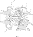
- a turbocharger 10 in accordance with one embodiment of the invention is illustrated in cross-sectional view in FIG. 1 .
- the turbocharger comprises a compressor 12 having a compressor wheel or impeller 14 mounted in a compressor housing 16 on one end of a rotatable shaft 18.
- the shaft is supported in bearings 19 mounted in a center housing 20 of the turbocharger.
- the shaft 18 is rotated by a turbine wheel 22 mounted on the other end of the shaft 18 from the compressor wheel, thereby rotatably driving the compressor wheel, which compresses air drawn in through the compressor inlet and delivers the compressed air to the intake of an internal combustion engine (not shown) for boosting the performance of the engine.
- the turbocharger also includes a turbine housing 24 that houses the turbine wheel 22.
- the turbine housing defines a generally annular chamber 26 that surrounds the turbine wheel and that receives exhaust gas from the internal combustion engine for driving the turbine wheel.
- the exhaust gas is directed from the chamber 26 generally radially inwardly through a turbine nozzle 28 to the turbine wheel 22.
- the gas As the exhaust gas flow through the passages between the blades 30 of the turbine wheel, the gas is expanded to a lower pressure, and the gas discharged from the wheel exits the turbine housing through a generally axial bore 32 therein.
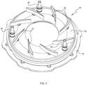
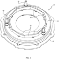
- FIGS. 2 through 7 depict a subassembly of the turbocharger, comprising a variable-vane assembly for the turbine nozzle 28 for varying the cross-sectional flow area through the nozzle so as to regulate flow into the turbine wheel.
- the assembly includes a plurality of vanes 34 that are circumferentially spaced about the nozzle.
- Each vane is affixed to an axle 36 that passes through a bearing aperture in a generally annular nozzle ring 38 that is mounted coaxially with respect to the turbine wheel 22.
- Each axle 36 is rotatable about its axis for rotating the attached vane.
- the nozzle ring 38 forms one wall of the flow passage of the nozzle 28.
- Each of the axles 36 has a vane arm 40 affixed to an end of the axle that protrudes out from the nozzle ring 38.
- Distal ends 41 of the vane arms 40 are engaged in generally U-shaped recesses 43 defined in the radially inner periphery of an annular unison ring 42 (also referred to as an actuator ring) that is rotatable about its axis and that is coaxial with the nozzle ring 38.
- Guides 39 mounted on the nozzle ring 38 are engaged with the inner periphery of the unison ring for guiding its rotational movement so that it remains substantially concentric with the nozzle ring, and for preventing the unison ring from moving in the axial direction away from the nozzle ring.
- An actuator (not shown) is connected to the unison ring 42 for rotating it about its axis.
- the vane arms 40 are rotated to cause the axles 36 to rotate about their axes, thereby rotating the vanes 34 so as to vary the cross-sectional flow area through the nozzle 28.
- variable vane mechanism is provided in the form of a unit or cartridge 50 ( FIG. 1 ) that is installable into and removable from the turbocharger.
- the unit 50 comprises the nozzle ring 38, vanes 34, axles 36, vane arms 40, and unison ring 42.
- the unit works in cooperation with an insert 52 having a tubular portion 54 received into the axial bore 32 of the turbine housing 24.
- the insert defines a nozzle portion 56 that extends radially outwardly from the tubular portion and is axially spaced from the nozzle ring 38 such that the vanes 34 extend between the nozzle ring 38 and the nozzle portion 56.
- the turbocharger includes a heat shroud 80 ( FIG. 1 ) that is captively retained between the nozzle ring 38 and the center housing 20 when the variable-vane unit 50 is installed into the turbocharger.
- the heat shroud 80 provides sealing between the nozzle ring and center housing to prevent hot exhaust gas from migrating between these parts into the cavity in which the vane arms 40 and unison ring 42 are disposed.
- the heat shroud 80 advantageously is a resiliently elastic material such as spring steel or the like, and the shroud is configured so that it is compressed in the axial direction between the nozzle ring 38 and the center housing 20 so that the restoring force of the shroud urges the nozzle ring 38 axially toward the turbine wheel 22 (to the right in FIG. 1 ).
- a plurality of spacers 60 are mounted to the nozzle ring 38 and project toward the nozzle portion 56 of the insert 52. Ends of the spacers 60 abut the nozzle portion 56 (as urged by the resilient heat shroud 80 described in the preceding paragraph) for maintaining the desired axial spacing between the nozzle portion 56 of the insert and the nozzle ring 38.
- the spacers thereby help ensure that there are small axial clearances between the ends of the vanes 34 and the nozzle ring 38 on one end and the nozzle portion 56 on the other end.
- the axial spacing set by the spacers 60 is designed to ensure that those clearance do not become too small, which could cause binding of the vanes, or too large, which could compromise turbine efficiency.
- FIG. 2 shows the vane side of the variable-vane assembly, with the vanes 34 in their fully open position, whereas FIG. 3 shows the vanes in their fully closed position.
- FIGS. 4 and 5 show the vane arm side of the assembly in the fully closed position
- FIGS. 6 and 7 show the vane arm side of the assembly in the fully open position.
- the unison ring 42 includes an actuator notch 45 for receiving an end of a crank (not shown) that is part of a kinematic chain between an actuator (not shown) and the unison ring. The crank is rotated by the actuator so as to impart rotational movement to the unison ring in a clockwise direction in FIGS.
- FIGS. 4-7 depict the unison ring having been rotated counterclockwise to the fully open position, thereby imparting counterclockwise rotation to the vane axles so that the vanes are placed in their fully open position.
- the unison ring 40 defines a plurality of locking tongues 44 that extend radially inwardly from the radially inner periphery of the ring.
- Each locking tongue is located proximate one of the recesses 43 and is on the vane-opening side of the recess. More particularly, with reference to FIG. 8 , which shows a single vane arm and the associated portion of the unison ring, each recess 43 in the unison ring has a vane-opening wall 43o and an opposite vane-closing wall 43c, and the distal end 41 of the vane arm 40 is disposed these two walls.
- the vane-opening wall 43o is the wall that exerts force on the distal end 41 of the vane arm in one direction to cause the vane arm to rotate its vane toward the open position
- the vane-closing wall 43c is the wall that exerts force on the distal end of the arm in the opposite direction to cause the arm to rotate the vane toward the closed position.
- the locking tongue 44 is proximate the vane-opening wall 43o as best seen in FIG. 8 .
- the invention addresses an issue with the variable-vane assembly relating to vibrations induced in the assembly by the internal combustion engine to which the turbocharger is coupled.
- the vibrations tend to cause a degree of relative vibratory motion between the vane arms and the unison ring recesses, as well as between the vane axles and the nozzle ring, that can induce excessive wear of the recesses and/or the vane arm ends and/or the vane axles and/or the nozzle ring.
- Such wear points can lead in some cases to the vanes becoming stuck in one position and/or contribute to poor regulation of the variable-vane assembly.
- the invention aims to mitigate the amount of engine vibration-induced wear within the variable-vane assembly.
- the locking tongues 44 are structured and arranged to provide constraint to the vane arms 40 when the variable-vane assembly is in the fully open position as best seen in FIG. 8 .
- Such constraint is created by the locking tongues contacting the shanks of the vane arms at a location intermediate the two opposite ends of eacg vane arm. This results in a three-point constraint of the arm.
- a first constraint point C1 is the attachment of the proximal end of the vane arm to the vane axle 36 and an associated contact point between the vane axle and the inner surface of the bearing aperture in the nozzle ring.
- a second constraint point is formed by the contact between the locking tongue 44 and the shank of the vane arm.
- a third constraint point C3 occurs between the vane arm distal end 41 and the vane-closing wall 43c of the unison ring recess 43.
- This three-point constraint essentially "locks" the vane arm in the fully open position, and indeed the constraint provided by the locking tongue actually defines the fully open position, such that no additional mechanism stop is needed.
- the locking tongues can serve a further function of defining the fully closed position of the vanes by virtue of at least one of the locking tongues coming into contact with at least one of the unison ring guides 39 as best seen in FIG. 4 . In such embodiments, the invention thus has the added benefit of reducing parts count and assembly steps.
- the locking action of the locking tongues substantially reduces the free play of the vane arm distal ends within the unison ring recesses. Accordingly, engine vibration-induced movements of the vane arms will result in impact forces between these components of a reduced magnitude relative to a conventional variable-vane assembly lacking the locking tongues of the present invention. While the locking action is effective only in the fully open vane position, it is still effective at reducing wear in view of the fact that the turbocharger spends a substantial fraction of its operating life at vehicle cruising conditions in which the vanes are fully open. It should be noted that for the locking tongues to be effective at reducing the vane arm movements, the actuator must continuously exert force on the unison ring toward the fully open position. Anti-back-drive action of the actuator kinematic chain is not sufficient to prevent engine vibrations from causing the vanes to be moved away from the fully open position, which would substantially eliminate the advantage provided by the locking tongues.
Landscapes
- Engineering & Computer Science (AREA)
- Mechanical Engineering (AREA)
- General Engineering & Computer Science (AREA)
- Chemical & Material Sciences (AREA)
- Combustion & Propulsion (AREA)
- Supercharger (AREA)
Claims (4)
- Turbolader, der eine Turbine mit variabler Düse aufweist und Folgendes umfasst:eine Turbinenbaugruppe, die ein Turbinengehäuse (24) und ein Turbinenrad (22) umfasst, das in dem Turbinengehäuse montiert und mit einer drehbaren Welle (18) zur Drehung mit dieser verbunden ist, wobei das Turbinengehäuse eine Kammer (26), die das Turbinenrad umgibt, definiert, um Abgas aufzunehmen und das Abgas dem Turbinenrad zuzuführen, wobei die Turbinenbaugruppe eine Düse (28) definiert, die von der Kammer radial nach innen zu dem Turbinenrad führt;eine Verdichterbaugruppe, die ein Verdichtergehäuse (16) und ein Verdichterrad (14) umfasst, das in dem Verdichtergehäuse montiert und mit der drehbaren Welle zur Drehung mit dieser verbunden ist;eine Baugruppe verstellbarer Leitschaufeln, die einen ringförmigen Düsenring (38) und eine Anordnung von Leitschaufeln (34), die in Umfangsrichtung um den Düsenring angrenzend an eine erste Fläche desselben beabstandet sind, und einen Verstellring (42) umfasst, der um eine zentrale Achse der Baugruppe verstellbarer Leitschaufeln drehbar ist, wobei der Verstellring eine Vielzahl von Aussparungen (43) in einem radial inneren Umfang des Verstellrings definiert, wobei die Leitschaufeln in der Düse derart angeordnet sind, dass Abgas zwischen den Leitschaufeln zum Turbinenrad strömt, wobei jede Leitschaufel mit einer Achse (36) verbunden ist, die durch eine Lageröffnung im Düsenring verläuft, wobei ein Ende jeder Achse aus der Lageröffnung an einer zweiten Fläche des Düsenrings gegenüber der ersten Fläche herausragt und mit einem Leitschaufelarm (40) an einem proximalen Ende des Leitschaufelarms verbunden ist, wobei die Leitschaufelarme distale Enden (41) aufweisen, die jeweils derart in den Aussparungen in dem radial inneren Umfang des Verstellrings aufgenommen sind, dass eine Drehung des Verstellrings um die zentrale Achse bewirkt, dass die Leitschaufelarme die Achsen schwenken und dadurch die Leitschaufeln zwischen einer vollständig geöffneten Position und einer vollständig geschlossenen Position und Zwischenpositionen dazwischen drehen, um den Abgasstrom zum Turbinenrad zu regulieren; undeine Verriegelungseinrichtung zum Verriegeln der Leitschaufeln in der vollständig geöffneten Position, wobei die Verriegelungseinrichtung eine Vielzahl von Verriegelungszungen (44) umfasst, die sich von dem radial inneren Umfang des Verstellrings radial nach innen erstrecken, wobei jede Verriegelungszunge an eine jeweilige der Aussparungen in dem radial inneren Umfang angrenzt, dadurch gekennzeichnet, dass sie so positioniert ist, dass sie mit einem jeweiligen der Leitschaufelarme an einer Stelle zwischen dem distalen Ende und dem proximalen Ende des Leitschaufelarms in der vollständig geöffneten Position in Kontakt steht.
- Turbolader nach Anspruch 1, wobei jede Aussparung in dem Verstellring eine Leitschaufel-Öffnungswand (43o) in der Nähe der jeweiligen Verriegelungszunge und eine Leitschaufel-Schließwand (43c) gegenüber der Leitschaufel-Öffnungswand umfasst, wobei das distale Ende jedes Leitschaufelarms (40) zwischen der Leitschaufel-Öffnungswand und der Leitschaufel-Schließwand angeordnet ist, und wobei jeder Leitschaufelarm in der vollständig geöffneten Position durch einen ersten Einschränkungspunkt (C1), der das proximale Ende des Leitschaufelarms umfasst, das mit der jeweiligen Leitschaufelachse verbunden ist, durch einen zweiten Einschränkungspunkt (C2), der die jeweilige Verriegelungszunge umfasst, die mit dem Leitschaufelarm zwischen dem proximalen und dem distalen Ende des Leitschaufelarms in Eingriff steht, und durch einen dritten Einschränkungspunkt (C3) eingeschränkt wird, der das distale Ende des Leitschaufelarms umfasst, das mit der Leitschaufel-Schließwand der jeweiligen Aussparung in dem Verstellring in Eingriff steht.
- Turbolader nach Anspruch 1 oder 2, wobei der Eingriff der Verriegelungszungen (44) mit den Leitschaufelarmen (40) die vollständig geöffnete Position der Leitschaufeln definiert, wobei die Baugruppe verstellbarer Leitschaufeln frei von zusätzlichen Arretiermechanismen ist, um die vollständig geöffnete Position zu definieren.
- Turbolader nach Anspruch 3, wobei die Baugruppe verstellbarer Leitschaufeln ferner eine Vielzahl von Führungen (39) umfasst, die an dem Düsenring befestigt sind und mit dem radial inneren Umfang des Verstellrings in Eingriff stehen, um die Drehbewegung des Verstellrings zu führen, und wobei der Eingriff von mindestens einer der Verriegelungszungen mit mindestens einer der Führungen die vollständig geschlossene Position der Leitschaufeln definiert.
Applications Claiming Priority (1)
| Application Number | Priority Date | Filing Date | Title |
|---|---|---|---|
| US17/457,038 US11506074B1 (en) | 2021-12-01 | 2021-12-01 | Turbocharger having variable-vane turbine nozzle including arrangement for locking the vanes in fully open position |
Publications (2)
| Publication Number | Publication Date |
|---|---|
| EP4191029A1 EP4191029A1 (de) | 2023-06-07 |
| EP4191029B1 true EP4191029B1 (de) | 2025-05-21 |
Family
ID=83270817
Family Applications (1)
| Application Number | Title | Priority Date | Filing Date |
|---|---|---|---|
| EP22194649.4A Active EP4191029B1 (de) | 2021-12-01 | 2022-09-08 | Turbolader mit turbinendüse mit variablen leitschaufeln mit anordnung zum verriegeln der leitschaufeln in vollständig geöffneter stellung |
Country Status (3)
| Country | Link |
|---|---|
| US (1) | US11506074B1 (de) |
| EP (1) | EP4191029B1 (de) |
| CN (1) | CN115680787B (de) |
Family Cites Families (13)
| Publication number | Priority date | Publication date | Assignee | Title |
|---|---|---|---|---|
| JP2003090212A (ja) * | 2001-09-18 | 2003-03-28 | Toyota Motor Corp | 内燃機関の排気浄化装置 |
| US9017017B2 (en) * | 2009-04-10 | 2015-04-28 | Honeywell Internatonal Inc. | Variable-vane assembly having fixed guide pins for unison ring |
| US8668443B2 (en) * | 2010-01-08 | 2014-03-11 | Honeywell International Inc. | Variable-vane assembly having unison ring guided radially by rollers and fixed members, and restrained axially by one or more fixed axial stops |
| US8915704B2 (en) * | 2011-06-15 | 2014-12-23 | Honeywell International Inc. | Turbocharger variable-nozzle assembly with vane sealing ring |
| US8967956B2 (en) * | 2011-09-26 | 2015-03-03 | Honeywell International Inc. | Turbocharger variable-nozzle assembly with vane sealing arrangement |
| WO2013116136A1 (en) * | 2012-02-02 | 2013-08-08 | Borgwarner Inc. | Mixed-flow turbocharger with variable turbine geometry |
| DE102015217438A1 (de) * | 2015-09-11 | 2017-03-30 | Bosch Mahle Turbo Systems Gmbh & Co. Kg | Verfahren zum Herstellen einer variablen Turbinengeometrie eines Abgasturboladers |
| DE102016203025A1 (de) * | 2016-02-26 | 2017-08-31 | Bosch Mahle Turbo Systems Gmbh & Co. Kg | Variable Turbinengeometrie |
| US10900415B2 (en) * | 2017-05-09 | 2021-01-26 | Garrett Transportation I Inc. | Turbocharger having a meridionally divided turbine housing and a variable turbine nozzle |
| US10619508B2 (en) * | 2017-11-03 | 2020-04-14 | Borgwarner, Inc. | Variable turbine geometry vane lever |
| EP3502483B1 (de) * | 2017-12-19 | 2020-09-02 | Cimos D.D. | Stützung eines turbomaschinenverstellrings durch schaufel-hebelarme |
| US10731488B2 (en) * | 2018-02-04 | 2020-08-04 | Garrett Transportation I Inc. | Turbocharger turbine assembly |
| US10927701B2 (en) * | 2019-03-12 | 2021-02-23 | Garrett Transportation I Inc. | Turbocharger having variable-vane turbine nozzle including spacers that also serve as hard stops for the vanes |
-
2021
- 2021-12-01 US US17/457,038 patent/US11506074B1/en active Active
-
2022
- 2022-09-08 EP EP22194649.4A patent/EP4191029B1/de active Active
- 2022-11-04 CN CN202211374758.2A patent/CN115680787B/zh active Active
Also Published As
| Publication number | Publication date |
|---|---|
| CN115680787A (zh) | 2023-02-03 |
| CN115680787B (zh) | 2023-05-30 |
| US11506074B1 (en) | 2022-11-22 |
| EP4191029A1 (de) | 2023-06-07 |
Similar Documents
| Publication | Publication Date | Title |
|---|---|---|
| EP3708780B1 (de) | Turbolader mit einem turbinenleitapparat mit verstellbaren schaufeln und abstandshaltern, die auch als anschläge für die schaufeln dienen | |
| EP1945928B2 (de) | Turbolader und patrone mit variabler düse dafür | |
| EP2171220B1 (de) | Schaufelanordnung mit variabler geometrie für einen turbolader | |
| EP2573363B1 (de) | Turbolader mit variabler Geometrie mit einer Schaufelabdichtungsanordnung | |
| EP2535524B1 (de) | Abgasturbolader umfassend eine Anordnung mit verstellbaren Düsen mit Schaufelabdichtring | |
| EP2594745B1 (de) | Anordnung mit verstellbaren Düsen für Turbolader mit Schaufelabdichtungsanordnung | |
| US6158956A (en) | Actuating mechanism for sliding vane variable geometry turbine | |
| EP3282097B1 (de) | Turbine mit variabler düse mit mitteln für radiale positionierung einer kartusche mit variablen düsen | |
| HUP0300055A2 (en) | Improved vane for variable nozzle turbocharger | |
| EP2176529B1 (de) | Turbolader mit variabler geometrie mit abstandshaltern | |
| EP2028347B1 (de) | Turbolader mit Schiebekolbenanordnung | |
| EP2320033B1 (de) | Turbolader mit variabler Geometrie und Führungsstiften | |
| EP4191029B1 (de) | Turbolader mit turbinendüse mit variablen leitschaufeln mit anordnung zum verriegeln der leitschaufeln in vollständig geöffneter stellung | |
| EP2730750B1 (de) | Turbolader und Kartusche mit variablen Düsen dafür | |
| EP2035673B1 (de) | Verstellbarer leitschaufelmechanismus für turbolader | |
| CN117980587A (zh) | 可变几何涡轮机 | |
| CN219317011U (zh) | 调节环、可变截面涡轮、涡轮机和增压设备 | |
| US11608775B1 (en) | Control method for variable turbine nozzle of turbocharger during engine braking |
Legal Events
| Date | Code | Title | Description |
|---|---|---|---|
| PUAI | Public reference made under article 153(3) epc to a published international application that has entered the european phase |
Free format text: ORIGINAL CODE: 0009012 |
|
| STAA | Information on the status of an ep patent application or granted ep patent |
Free format text: STATUS: REQUEST FOR EXAMINATION WAS MADE |
|
| 17P | Request for examination filed |
Effective date: 20220908 |
|
| AK | Designated contracting states |
Kind code of ref document: A1 Designated state(s): AL AT BE BG CH CY CZ DE DK EE ES FI FR GB GR HR HU IE IS IT LI LT LU LV MC MK MT NL NO PL PT RO RS SE SI SK SM TR |
|
| GRAP | Despatch of communication of intention to grant a patent |
Free format text: ORIGINAL CODE: EPIDOSNIGR1 |
|
| STAA | Information on the status of an ep patent application or granted ep patent |
Free format text: STATUS: GRANT OF PATENT IS INTENDED |
|
| GRAS | Grant fee paid |
Free format text: ORIGINAL CODE: EPIDOSNIGR3 |
|
| GRAA | (expected) grant |
Free format text: ORIGINAL CODE: 0009210 |
|
| STAA | Information on the status of an ep patent application or granted ep patent |
Free format text: STATUS: THE PATENT HAS BEEN GRANTED |
|
| INTG | Intention to grant announced |
Effective date: 20250319 |
|
| AK | Designated contracting states |
Kind code of ref document: B1 Designated state(s): AL AT BE BG CH CY CZ DE DK EE ES FI FR GB GR HR HU IE IS IT LI LT LU LV MC MK MT NL NO PL PT RO RS SE SI SK SM TR |
|
| REG | Reference to a national code |
Ref country code: GB Ref legal event code: FG4D |
|
| REG | Reference to a national code |
Ref country code: CH Ref legal event code: EP |
|
| REG | Reference to a national code |
Ref country code: DE Ref legal event code: R096 Ref document number: 602022014892 Country of ref document: DE |
|
| REG | Reference to a national code |
Ref country code: IE Ref legal event code: FG4D |
|
| REG | Reference to a national code |
Ref country code: NL Ref legal event code: MP Effective date: 20250521 |
|
| PG25 | Lapsed in a contracting state [announced via postgrant information from national office to epo] |
Ref country code: FI Free format text: LAPSE BECAUSE OF FAILURE TO SUBMIT A TRANSLATION OF THE DESCRIPTION OR TO PAY THE FEE WITHIN THE PRESCRIBED TIME-LIMIT Effective date: 20250521 Ref country code: PT Free format text: LAPSE BECAUSE OF FAILURE TO SUBMIT A TRANSLATION OF THE DESCRIPTION OR TO PAY THE FEE WITHIN THE PRESCRIBED TIME-LIMIT Effective date: 20250922 Ref country code: ES Free format text: LAPSE BECAUSE OF FAILURE TO SUBMIT A TRANSLATION OF THE DESCRIPTION OR TO PAY THE FEE WITHIN THE PRESCRIBED TIME-LIMIT Effective date: 20250521 |
|
| PGFP | Annual fee paid to national office [announced via postgrant information from national office to epo] |
Ref country code: DE Payment date: 20250926 Year of fee payment: 4 |
|
| REG | Reference to a national code |
Ref country code: LT Ref legal event code: MG9D |
|
| PG25 | Lapsed in a contracting state [announced via postgrant information from national office to epo] |
Ref country code: NO Free format text: LAPSE BECAUSE OF FAILURE TO SUBMIT A TRANSLATION OF THE DESCRIPTION OR TO PAY THE FEE WITHIN THE PRESCRIBED TIME-LIMIT Effective date: 20250821 Ref country code: GR Free format text: LAPSE BECAUSE OF FAILURE TO SUBMIT A TRANSLATION OF THE DESCRIPTION OR TO PAY THE FEE WITHIN THE PRESCRIBED TIME-LIMIT Effective date: 20250822 |
|
| PG25 | Lapsed in a contracting state [announced via postgrant information from national office to epo] |
Ref country code: PL Free format text: LAPSE BECAUSE OF FAILURE TO SUBMIT A TRANSLATION OF THE DESCRIPTION OR TO PAY THE FEE WITHIN THE PRESCRIBED TIME-LIMIT Effective date: 20250521 Ref country code: NL Free format text: LAPSE BECAUSE OF FAILURE TO SUBMIT A TRANSLATION OF THE DESCRIPTION OR TO PAY THE FEE WITHIN THE PRESCRIBED TIME-LIMIT Effective date: 20250521 |
|
| PG25 | Lapsed in a contracting state [announced via postgrant information from national office to epo] |
Ref country code: BG Free format text: LAPSE BECAUSE OF FAILURE TO SUBMIT A TRANSLATION OF THE DESCRIPTION OR TO PAY THE FEE WITHIN THE PRESCRIBED TIME-LIMIT Effective date: 20250521 |
|
| PG25 | Lapsed in a contracting state [announced via postgrant information from national office to epo] |
Ref country code: HR Free format text: LAPSE BECAUSE OF FAILURE TO SUBMIT A TRANSLATION OF THE DESCRIPTION OR TO PAY THE FEE WITHIN THE PRESCRIBED TIME-LIMIT Effective date: 20250521 |
|
| PGFP | Annual fee paid to national office [announced via postgrant information from national office to epo] |
Ref country code: FR Payment date: 20250925 Year of fee payment: 4 |
|
| PG25 | Lapsed in a contracting state [announced via postgrant information from national office to epo] |
Ref country code: RS Free format text: LAPSE BECAUSE OF FAILURE TO SUBMIT A TRANSLATION OF THE DESCRIPTION OR TO PAY THE FEE WITHIN THE PRESCRIBED TIME-LIMIT Effective date: 20250821 |
|
| PG25 | Lapsed in a contracting state [announced via postgrant information from national office to epo] |
Ref country code: IS Free format text: LAPSE BECAUSE OF FAILURE TO SUBMIT A TRANSLATION OF THE DESCRIPTION OR TO PAY THE FEE WITHIN THE PRESCRIBED TIME-LIMIT Effective date: 20250921 |
|
| PG25 | Lapsed in a contracting state [announced via postgrant information from national office to epo] |
Ref country code: LV Free format text: LAPSE BECAUSE OF FAILURE TO SUBMIT A TRANSLATION OF THE DESCRIPTION OR TO PAY THE FEE WITHIN THE PRESCRIBED TIME-LIMIT Effective date: 20250521 |
|
| REG | Reference to a national code |
Ref country code: AT Ref legal event code: MK05 Ref document number: 1796915 Country of ref document: AT Kind code of ref document: T Effective date: 20250521 |
|
| PG25 | Lapsed in a contracting state [announced via postgrant information from national office to epo] |
Ref country code: SM Free format text: LAPSE BECAUSE OF FAILURE TO SUBMIT A TRANSLATION OF THE DESCRIPTION OR TO PAY THE FEE WITHIN THE PRESCRIBED TIME-LIMIT Effective date: 20250521 Ref country code: DK Free format text: LAPSE BECAUSE OF FAILURE TO SUBMIT A TRANSLATION OF THE DESCRIPTION OR TO PAY THE FEE WITHIN THE PRESCRIBED TIME-LIMIT Effective date: 20250521 Ref country code: AT Free format text: LAPSE BECAUSE OF FAILURE TO SUBMIT A TRANSLATION OF THE DESCRIPTION OR TO PAY THE FEE WITHIN THE PRESCRIBED TIME-LIMIT Effective date: 20250521 |
|
| PG25 | Lapsed in a contracting state [announced via postgrant information from national office to epo] |
Ref country code: CZ Free format text: LAPSE BECAUSE OF FAILURE TO SUBMIT A TRANSLATION OF THE DESCRIPTION OR TO PAY THE FEE WITHIN THE PRESCRIBED TIME-LIMIT Effective date: 20250521 |
|
| PG25 | Lapsed in a contracting state [announced via postgrant information from national office to epo] |
Ref country code: EE Free format text: LAPSE BECAUSE OF FAILURE TO SUBMIT A TRANSLATION OF THE DESCRIPTION OR TO PAY THE FEE WITHIN THE PRESCRIBED TIME-LIMIT Effective date: 20250521 |
|
| PG25 | Lapsed in a contracting state [announced via postgrant information from national office to epo] |
Ref country code: SK Free format text: LAPSE BECAUSE OF FAILURE TO SUBMIT A TRANSLATION OF THE DESCRIPTION OR TO PAY THE FEE WITHIN THE PRESCRIBED TIME-LIMIT Effective date: 20250521 |
|
| PG25 | Lapsed in a contracting state [announced via postgrant information from national office to epo] |
Ref country code: IT Free format text: LAPSE BECAUSE OF FAILURE TO SUBMIT A TRANSLATION OF THE DESCRIPTION OR TO PAY THE FEE WITHIN THE PRESCRIBED TIME-LIMIT Effective date: 20250521 |
|
| REG | Reference to a national code |
Ref country code: DE Ref legal event code: R097 Ref document number: 602022014892 Country of ref document: DE |
|
| PG25 | Lapsed in a contracting state [announced via postgrant information from national office to epo] |
Ref country code: RO Free format text: LAPSE BECAUSE OF FAILURE TO SUBMIT A TRANSLATION OF THE DESCRIPTION OR TO PAY THE FEE WITHIN THE PRESCRIBED TIME-LIMIT Effective date: 20250521 |
|
| PLBE | No opposition filed within time limit |
Free format text: ORIGINAL CODE: 0009261 |
|
| STAA | Information on the status of an ep patent application or granted ep patent |
Free format text: STATUS: NO OPPOSITION FILED WITHIN TIME LIMIT |
|
| REG | Reference to a national code |
Ref country code: CH Ref legal event code: L10 Free format text: ST27 STATUS EVENT CODE: U-0-0-L10-L00 (AS PROVIDED BY THE NATIONAL OFFICE) Effective date: 20260402 |
|
| 26N | No opposition filed |
Effective date: 20260224 |