EP4191094A1 - Actionneur a cable a sensibilite en effort amelioree - Google Patents
Actionneur a cable a sensibilite en effort amelioree Download PDFInfo
- Publication number
- EP4191094A1 EP4191094A1 EP22209679.4A EP22209679A EP4191094A1 EP 4191094 A1 EP4191094 A1 EP 4191094A1 EP 22209679 A EP22209679 A EP 22209679A EP 4191094 A1 EP4191094 A1 EP 4191094A1
- Authority
- EP
- European Patent Office
- Prior art keywords
- nut
- cable
- wire
- screw
- actuator
- Prior art date
- Legal status (The legal status is an assumption and is not a legal conclusion. Google has not performed a legal analysis and makes no representation as to the accuracy of the status listed.)
- Granted
Links
Images




Classifications
-
- F—MECHANICAL ENGINEERING; LIGHTING; HEATING; WEAPONS; BLASTING
- F16—ENGINEERING ELEMENTS AND UNITS; GENERAL MEASURES FOR PRODUCING AND MAINTAINING EFFECTIVE FUNCTIONING OF MACHINES OR INSTALLATIONS; THERMAL INSULATION IN GENERAL
- F16H—GEARING
- F16H25/00—Gearings comprising primarily only cams, cam-followers and screw-and-nut mechanisms
- F16H25/18—Gearings comprising primarily only cams, cam-followers and screw-and-nut mechanisms for conveying or interconverting oscillating or reciprocating motions
- F16H25/20—Screw mechanisms
-
- F—MECHANICAL ENGINEERING; LIGHTING; HEATING; WEAPONS; BLASTING
- F16—ENGINEERING ELEMENTS AND UNITS; GENERAL MEASURES FOR PRODUCING AND MAINTAINING EFFECTIVE FUNCTIONING OF MACHINES OR INSTALLATIONS; THERMAL INSULATION IN GENERAL
- F16H—GEARING
- F16H19/00—Gearings comprising essentially only toothed gears or friction members and not capable of conveying indefinitely-continuing rotary motion
- F16H19/02—Gearings comprising essentially only toothed gears or friction members and not capable of conveying indefinitely-continuing rotary motion for interconverting rotary or oscillating motion and reciprocating motion
- F16H19/06—Gearings comprising essentially only toothed gears or friction members and not capable of conveying indefinitely-continuing rotary motion for interconverting rotary or oscillating motion and reciprocating motion comprising flexible members, e.g. an endless flexible member
- F16H19/0622—Gearings comprising essentially only toothed gears or friction members and not capable of conveying indefinitely-continuing rotary motion for interconverting rotary or oscillating motion and reciprocating motion comprising flexible members, e.g. an endless flexible member for converting reciprocating movement into oscillating movement and vice versa, the reciprocating movement is perpendicular to the axis of oscillation
-
- F—MECHANICAL ENGINEERING; LIGHTING; HEATING; WEAPONS; BLASTING
- F16—ENGINEERING ELEMENTS AND UNITS; GENERAL MEASURES FOR PRODUCING AND MAINTAINING EFFECTIVE FUNCTIONING OF MACHINES OR INSTALLATIONS; THERMAL INSULATION IN GENERAL
- F16H—GEARING
- F16H25/00—Gearings comprising primarily only cams, cam-followers and screw-and-nut mechanisms
- F16H25/18—Gearings comprising primarily only cams, cam-followers and screw-and-nut mechanisms for conveying or interconverting oscillating or reciprocating motions
- F16H25/20—Screw mechanisms
- F16H25/2015—Means specially adapted for stopping actuators in the end position; Position sensing means
-
- F—MECHANICAL ENGINEERING; LIGHTING; HEATING; WEAPONS; BLASTING
- F16—ENGINEERING ELEMENTS AND UNITS; GENERAL MEASURES FOR PRODUCING AND MAINTAINING EFFECTIVE FUNCTIONING OF MACHINES OR INSTALLATIONS; THERMAL INSULATION IN GENERAL
- F16H—GEARING
- F16H25/00—Gearings comprising primarily only cams, cam-followers and screw-and-nut mechanisms
- F16H25/18—Gearings comprising primarily only cams, cam-followers and screw-and-nut mechanisms for conveying or interconverting oscillating or reciprocating motions
- F16H25/20—Screw mechanisms
- F16H25/24—Elements essential to such mechanisms, e.g. screws, nuts
-
- F—MECHANICAL ENGINEERING; LIGHTING; HEATING; WEAPONS; BLASTING
- F16—ENGINEERING ELEMENTS AND UNITS; GENERAL MEASURES FOR PRODUCING AND MAINTAINING EFFECTIVE FUNCTIONING OF MACHINES OR INSTALLATIONS; THERMAL INSULATION IN GENERAL
- F16H—GEARING
- F16H19/00—Gearings comprising essentially only toothed gears or friction members and not capable of conveying indefinitely-continuing rotary motion
- F16H19/02—Gearings comprising essentially only toothed gears or friction members and not capable of conveying indefinitely-continuing rotary motion for interconverting rotary or oscillating motion and reciprocating motion
- F16H19/06—Gearings comprising essentially only toothed gears or friction members and not capable of conveying indefinitely-continuing rotary motion for interconverting rotary or oscillating motion and reciprocating motion comprising flexible members, e.g. an endless flexible member
- F16H2019/0681—Gearings comprising essentially only toothed gears or friction members and not capable of conveying indefinitely-continuing rotary motion for interconverting rotary or oscillating motion and reciprocating motion comprising flexible members, e.g. an endless flexible member the flexible member forming a closed loop
- F16H2019/0686—Gearings comprising essentially only toothed gears or friction members and not capable of conveying indefinitely-continuing rotary motion for interconverting rotary or oscillating motion and reciprocating motion comprising flexible members, e.g. an endless flexible member the flexible member forming a closed loop the flexible member being directly driven by a pulley or chain wheel
-
- F—MECHANICAL ENGINEERING; LIGHTING; HEATING; WEAPONS; BLASTING
- F16—ENGINEERING ELEMENTS AND UNITS; GENERAL MEASURES FOR PRODUCING AND MAINTAINING EFFECTIVE FUNCTIONING OF MACHINES OR INSTALLATIONS; THERMAL INSULATION IN GENERAL
- F16H—GEARING
- F16H25/00—Gearings comprising primarily only cams, cam-followers and screw-and-nut mechanisms
- F16H25/18—Gearings comprising primarily only cams, cam-followers and screw-and-nut mechanisms for conveying or interconverting oscillating or reciprocating motions
- F16H25/20—Screw mechanisms
- F16H2025/204—Axial sliding means, i.e. for rotary support and axial guiding of nut or screw shaft
-
- F—MECHANICAL ENGINEERING; LIGHTING; HEATING; WEAPONS; BLASTING
- F16—ENGINEERING ELEMENTS AND UNITS; GENERAL MEASURES FOR PRODUCING AND MAINTAINING EFFECTIVE FUNCTIONING OF MACHINES OR INSTALLATIONS; THERMAL INSULATION IN GENERAL
- F16H—GEARING
- F16H25/00—Gearings comprising primarily only cams, cam-followers and screw-and-nut mechanisms
- F16H25/18—Gearings comprising primarily only cams, cam-followers and screw-and-nut mechanisms for conveying or interconverting oscillating or reciprocating motions
- F16H25/20—Screw mechanisms
- F16H2025/2062—Arrangements for driving the actuator
- F16H2025/2075—Coaxial drive motors
Definitions
- the invention relates to a cable actuator comprising a screw/nut assembly, the nut of which is movable in translation and coupled by a cable to an element to be moved and which is provided with a force sensor.
- the invention relates more particularly to cable actuators, the cable of which performs a function of anti-rotation of the nut relative to the screw.
- It is known cable actuators comprising a screw mounted on a frame and a nut cooperating with the screw.
- the nut is associated with anti-rotation means so that a relative rotation of the screw and the nut causes an axial displacement of the nut.
- One or more cables associated with the nut are connected to an output of the actuator which can be rotary (when the cables are connected to pulleys) or linear (when the cables are connected directly to the load to be handled).
- the force sensors for such actuators are generally mounted directly on the output of the actuator and turn out to be bulky, expensive and/or inaccurate.
- these force sensors being directly coupled to the segments of the articulated arm, they support shocks and vibrations originating from the segments and from the loads which they support. To avoid excessive fragility, they must therefore be oversized, which increases their volume and decreases their sensitivity.
- the force control of cable actuators which have advantageous characteristics, particularly in terms of compactness, is difficult or expensive, which restricts their distribution.
- the object of the invention is to improve the precision and the manufacturing and/or maintenance costs of a cable actuator.
- An actuator provided with a simple sensor which performs a precise measurement of the angular position of the nut is thus obtained.
- Implanting the first point improves the sensitivity of the sensor by reducing the maximum travel of the sensor.
- the ratio of the useful displacement of the sensor to its total displacement is representative of the signal/noise ratio of the sensor which is then, thanks to the invention, improved.
- the first distance is between forty percent and sixty percent of the stroke, preferably fifty percent.
- the first point is located at a second non-zero distance from a straight line connecting the first axis and the connecting point.
- the change in curvature of the wire is carried out by a drum of the winder.
- the distance sensor comprises a drum wire winder, and the change in curvature of the wire is carried out by the drum of the winder.
- the wire can make a plurality of turns on a drum of the winder.
- the wire distance sensor includes a linear displacement sensor.
- the actuator of the invention comprises a frame 10, here a right cylinder portion 11 comprising a base 12 at the center of which a bearing 13 accommodates a screw 2 rotating about a first horizontal axis Ox .
- the screw 2 is a ball screw of pitch p 2 which is driven in rotation by an electric motor 3 comprising a first rotary encoder 3.1.
- a nut 4 cooperates with the screw 2 and comprises a first eyelet 5 projecting radially from the nut 4.
- a first cable 6 extends parallel to the first axis Ox and comprises a first section 6.1 held at its first end 6.2 in the first eyelet 5 by a first crimp 7.1.
- the second end 6.3 of the first section 6.1 of the first cable 6 is crimped onto a first pulley 14 secured to a first shaft 16 rotatably mounted on the frame 10 along an axis perpendicular to the first axis Ox.
- the first cable 6 also comprises a second section 6.4 of the first cable 6 extending parallel to the first axis Ox on either side of a plane P orthogonal to the first axis Ox comprising the first eyelet 5 and which is held in its first end 6.5 in the first eyelet 5 by the first crimp 7.1.
- the second end 6.6 of the second section 6.4 of the first cable 6 is crimped onto a second pulley 15 secured to a second shaft 17 rotatably mounted on the frame 10 along an axis perpendicular to the first axis Ox.
- the nut 4 comprises a second eyelet 8 projecting radially from the nut 4 so as to be diametrically opposed to the first eyelet 5.
- a second cable 9 extends parallel to the first axis Ox and comprises a first section 9.1 of second cable 9 maintained at its first end 9.2 in the second eyelet 8 by a second crimp 7.2.
- the second end 9.3 of the first section 9.1 of the second cable 9 is connected to a third pulley 18 integral with the first shaft 16 rotatably mounted on the frame 10 along an axis perpendicular to the first axis Ox.
- the second cable 9 also comprises a second section 9.4 extending parallel to the first axis Ox from and on the other side of a plane P orthogonal to the first axis Ox comprising the second eyelet 8 and which is held at its first end 9.5 in the second eyelet 8 by the second crimp 7.2.
- the second end 9.6 of the second section 9.4 of the second cable 9 is crimped onto a fourth pulley 19 secured to the second shaft 17 rotatably mounted on the frame 10 along an axis perpendicular to the first axis Ox.
- the first cable 6 and second cable 9 are each precharged to a precharge voltage t6.9 equal to half the total precharge voltage t 0 , for example by acting on the distance separating the first shaft 16 and the second shaft 17.
- the actuator 100 also comprises a fifth pulley 20 and a sixth pulley 21 respectively integral in rotation with the first shaft 16 and the second shaft 17.
- a third cable 22 extends between the fifth pulley 20 and the sixth pulley 21 and comprises a first end 22.1 crimped on the fifth pulley 20 and a second end 22.2 crimped on the sixth pulley 21.
- a support 22.3 is crimped on the third cable 22 to constitute an output 22.4 of the actuator 100 intended to be connected to a load 101 to be moved.
- the motor 3 and its encoder 3.1 are connected to a control unit 90 comprising a unit 91 for determining the position of the nut 4, a comparator 92, a computer 93, a memory 94 and a display 95.
- a handle control 96 is also connected to the control unit 90.
- the first cable 6 and the second cable 9 being stretched, they exert forces opposing a training in rotation of the nut 4 by the screw 2 during rotation of the motor 3 in both directions of movement of the nut 4 relative to the screw 2. They then perform - in addition to their function of transmitting displacement forces from nut 4 to load 101 - an anti-rotation function so that rotation of screw 2 under the action of motor 3 causes movement of nut 4 relative to screw 2 between a first extreme position E1 and a second extreme position E2 of the nut 4, shown in dotted lines on the figure 1 .
- the first position E1 and the second position E2 are separated by a stroke C.
- the cable actuator 100 of the invention allows movement of the load 101 in two opposite directions.
- a distance sensor 30 with winder 31 of wire 32 is integral with frame 10.
- Wire 32 comprises a first end 32.1 of wire 32 connected to nut 4 at a connection point 4.1.
- the wire 32 is engaged on a drum 33 of the winder 31 at a first point 34 (point of tangency) and makes several turns on the drum 33.
- the drum 33 has a diameter D33.
- a spiral spring 35 exerts a return force on the drum 33 and maintains a permanent tension in the wire 32.
- a rotary encoder 40 measures the rotation of the drum 33.
- the rotary encoder 40 of the distance sensor 30 is connected to a unit of treatment 41, itself connected to the control unit 90.
- the wire 32 performs a change of curvature at the first point 34 during its winding on the drum 33.
- the point 34 is located in an orthogonal plane P1 to the first axis Ox and the plane P1 is located at a first distance d1 from the first extreme point E1.
- the distance d1 is equal to fifty percent of the stroke C.
- the point 34 is, here, located in a median plane P1 of the stroke C of the nut 4.
- the point 34 is also located at a second non-zero distance d2 from a straight line D1 which connects the connection point 4.1 and the axis Ox.
- a user acts on the handle 96 to control a displacement of the load 101.
- the unit 90 then controls a rotation of the motor 3.
- the rotation of the screw 2 causes an identical rotation of the nut 4 due to contact friction between the screw 2 and the nut 4.
- This rotation puts tension on the first cable 6 and the second cable 9 which then come to exert forces opposing a drive in rotation of the nut 4 by the screw 2.
- the first cable 6 and the second cable 9 then perform - in addition to their function of transmitting displacement forces to the load 101 - an anti-rotation function so that a rotation of screw 2 under the action of motor 3 causes nut 4 to move relative to screw 2.
- the unit 91 determines, during a first step, a theoretical position of the nut 4 on the screw 2 based on the number of engine revolutions N measured by encoder 3.1. The unit 91 thus establishes a theoretical linear position of the nut 4 on the screw 2 along the first axis Ox, but also a theoretical angular position of the nut 4 around the first axis Ox. The theoretical position linear of the nut 4 on the screw 2 corresponds to the position according to the first axis Ox that the nut 4 on the screw 2 would occupy after a number of turns N without load, that is to say for a zero mass of the load 101.
- the theoretical angular position of the nut 4 around the axis Ox corresponds to the position around the axis Ox that the nut 4 would occupy on the screw 2 after a number of turns N off load, that is to say for a zero mass of the load 101.
- This theoretical angular position can vary according to the theoretical linear position of the nut 4 on the screw 2.
- the positions angular and linear are measured in an orthonormal frame (Ox, Oy, Oz) linked to nut 4.
- the actual position of the nut 4 on the screw 2 is determined by the number of rotations of the drum 33 recorded by the rotary encoder 40.
- the processing unit 41 measures the rotation ⁇ of the rotary encoder 40 and transmits it to the unit control 90.
- the comparator 92 compares the actual angular position of the nut 4 around the axis Ox with the theoretical angular position of the nut around the axis Ox and, by subtraction, the comparator 92 obtains a value ⁇ ang4 of the deviation of the angular position of the nut 4.
- Computer 93 determines a force applied to support 22.3 by load 101 as a function of the value ⁇ ang4 of the deviation in the angular position of nut 4.
- a cable actuator 100 is thus obtained whose sensor 30 allows an estimation of the tensions in the first cable 6 and the second cable 9 and thus to deduce therefrom a force exerted on the output 22.4 of the actuator 100.
- the position of the point 34 on the drum 33 varies according to the position of the nut 4 on the screw 2.
- the position of the plane P1, and therefore the distance d1 varies during the displacement of the nut 4 on the screw 2. It It is possible, as a first approach, to estimate that the distance d1 varies over an amplitude range substantially equal to half the diameter D33.
- the actuator 100 comprises a wire return made here in the form of a pulley 36 for return.
- the wire 32 extends from the connection point 4.1 to the pulley 36 on which it engages at the point 34 of tangency of the wire 32 on the pulley 36.
- the wire 32 then performs a change of curvature at the point 34.
- wire 32 extends, here in a direction substantially parallel to axis Ox, as far as drum 33.
- the distance d1 which separates the plane P1 from the extreme position E1 varies with the position of the nut 4 on the screw 2 while remaining included between forty percent ( figure 4 ) and sixty percent ( figure 5 ) of stroke C.
- the wire 32 may comprise a first portion 32.2 between the points 32.1 and 34, and a second portion 32.3 between the point 31 and the pulley 36 which has an offset relative to to a second winding plane P2 of the wire 32 on the pulley 36.
- the pulley 36 can be mounted for example in a yoke pivotally mounted on a pivot axis orthogonal to the axis of rotation of the pulley 36 of so that the plane P2 constantly passes through the portions 32.2 and 32.3 of the wire 32.
- the pivot axis must be parallel and close to the portion 32.3 and ideally concentric. If the pivot axis is mounted on a bearing, for example, even a low tension in the wire 32 will be sufficient to automatically maintain the pulley 36 in the plane of the two portions 32.2 and 32.3.
- the distance sensor 30 with wire 32 may comprise a linear return sensor to which a second end of the wire 32 is connected.
Landscapes
- Engineering & Computer Science (AREA)
- General Engineering & Computer Science (AREA)
- Mechanical Engineering (AREA)
- Transmission Devices (AREA)
Abstract
- un châssis (10) ;
- une vis (2) montée à rotation sur le châssis (10) et s'étendant selon un premier axe (Ox) ;
- un écrou (4) coopérant avec la vis (2) ;
- des moyens de déterminer (30) un déplacement angulaire de l'écrou (4) autour du premier axe (Ox) relativement au châssis (10); et
un capteur de distance (30) à enrouleur (33) de fil (32) solidaire du châssis (10), une extrémité (32.1) du fil (32) étant reliée à l'écrou (4) en un point de liaison (4.1),
dans lequel le capteur de distance (30) est agencé de manière à ce que le fil (32) effectue un changement de courbure en un premier point (34) situé dans un premier plan (P1) orthogonal au premier axe (Ox).
Description
- L'invention concerne un actionneur à câble comportant un ensemble vis/écrou dont l'écrou est mobile en translation et attelé par un câble à un élément à déplacer et qui est pourvu d'un capteur d'effort. L'invention concerne plus particulièrement les actionneurs à câble dont le câble réalise une fonction d'anti-rotation de l'écrou par rapport à la vis.
- Il est connu des actionneurs à câbles comportant une vis montée sur un châssis et un écrou coopérant avec la vis. L'écrou est associé à des moyens d'anti-rotation de sorte qu'une rotation relative de la vis et de l'écrou provoque un déplacement axial de l'écrou. Un ou plusieurs câbles associés à l'écrou sont reliés à une sortie de l'actionneur qui peut être rotative (lorsque les câbles sont reliés à des poulies) ou linéaire (lorsque les câbles sont reliés directement à la charge à manipuler).
- Les capteurs d'effort pour de tels actionneurs sont généralement montés directement sur la sortie de l'actionneur et se révèlent encombrants, chers et/ou peu précis. En outre, ces capteurs d'effort étant directement accouplés aux segments du bras articulé, ils supportent des chocs et vibrations en provenance des segments et des charges qu'ils supportent. Pour éviter une trop grande fragilité, ils doivent donc être surdimensionnés ce qui augmente leur volume et diminue leur sensibilité. Ainsi, le pilotage en effort des actionneurs à câble, qui disposent de caractéristiques intéressantes notamment en termes de compacité, est malaisé ou couteux ce qui restreint leur diffusion.
- L'invention a pour objet d'améliorer la précision et les coûts de fabrication et/ou de maintenance d'un actionneur à câble.
- A cet effet, on prévoit, un actionneur à câble comprenant :
- un châssis;
- une vis montée à rotation sur le châssis et s'étendant selon un premier axe;
- un écrou coopérant avec la vis ;
- un premier câble attelé à l'écrou et fonctionnellement relié à une sortie de l'actionneur ;
- un deuxième câble attelé à l'écrou et fonctionnellement relié à la sortie de l'actionneur;
- un moteur agencé pour entrainer en rotation la vis;
- le premier câble étant agencé pour exercer des efforts s'opposant à un entraînement en rotation de l'écrou par la vis pour constituer des moyens d'anti-rotation de sorte qu'une rotation de la vis sous l'action du moteur provoque un déplacement de l'écrou sur la vis entre une première position extrême et une deuxième position extrême qui délimitent une course de l'écrou,
- l'actionneur à câble comprenant également :
- des moyens de déterminer un déplacement angulaire de l'écrou autour du premier axe relativement au châssis; et
- des moyens de déterminer un effort appliqué sur la sortie de l'actionneur à câble en fonction du déplacement angulaire de l'écrou autour du premier axe, dans lequel les moyens de déterminer le déplacement angulaire de l'écrou comprennent un capteur de distance à fil solidaire du châssis, une extrémité du fil étant reliée à l'écrou en un point de liaison. Selon l'invention, le capteur de distance est agencé de manière à ce que le fil effectue un changement de courbure en un premier point situé dans un premier plan orthogonal au premier axe, le plan étant situé à une première distance du premier point extrême comprise entre trente et soixante-dix pour cent de la course.
- On obtient ainsi un actionneur pourvu d'un capteur simple qui réalise une mesure précise de la position angulaire de l'écrou. L'implantation du premier point améliore la sensibilité du capteur en réduisant la course maximale du capteur. Le rapport du déplacement utile du capteur sur son déplacement total est représentatif du rapport signal/bruit du capteur qui est alors, grâce à l'invention, amélioré.
- Avantageusement, la première distance est comprise entre quarante pour cent et soixante pour cent de la course, préférentiellement cinquante pour cent.
- Avantageusement, le premier point est situé à une deuxième distance non nulle d'une droite reliant le premier axe et le point de liaison.
- Avantageusement, le changement de courbure du fil est réalisé par un tambour de l'enrouleur.
- Il est possible d'adapter l'implantation du capteur en fonction d'autres exigences de conception lorsque le changement de courbure du fil est réalisé par un renvoi de fil, pouvant comprendre une poulie.
- Préférentiellement, le capteur de distance comprend un enrouleur de fil à tambour, et le changement de courbure du fil est réalisé par le tambour de l'enrouleur. Le fil peut effectuer une pluralité de tours sur un tambour de l'enrouleur.
- Alternativement, le capteur de distance à fil comprend un capteur de déplacement linéaire.
- D'autres caractéristiques et avantages de l'invention ressortiront à la lecture de la description qui suit d'un mode de réalisation particulier et non limitatif de l'invention.
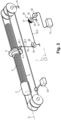
- Il sera fait référence aux dessins annexés, parmi lesquels :
- [
Fig. 1 ] lafigure 1 est une vue schématique en perspective partielle d'un vérin à câble; - [
Fig. 2 ] lafigure 2 est une vue schématique en perspective d'un premier mode de réalisation de l'invention ; - [
Fig. 3 ] lafigure 3 est une vue schématique en perspective d'un deuxième mode de réalisation de l'invention. - [
Fig. 4 ] lafigure 4 est une vue schématique en perspective de l'invention de lafigure 3 dans une première configuration ; - [
Fig. 5 ] lafigure 5 est une vue schématique en perspective de l'invention de lafigure 3 dans une deuxième configuration. - En référence à la
figure 1 , l'actionneur de l'invention, généralement désigné 100, comprend un châssis 10, ici une portion de cylindre 11 droit comprenant une base 12 au centre de laquelle un palier 13 accueille une vis 2 à rotation autour d'un premier axe Ox horizontal. La vis 2 est une vis à billes de pas p2 qui est entraînée en rotation par un moteur électrique 3 comprenant un premier codeur rotatif 3.1. Un écrou 4 coopère avec la vis 2 et comprend un premier oeillet 5 en saillie radiale de l'écrou 4. Un premier câble 6 s'étend parallèlement au premier axe Ox et comprend un premier tronçon 6.1 maintenu en sa première extrémité 6.2 dans le premier œillet 5 par une première sertissure 7.1. La deuxième extrémité 6.3 du premier tronçon 6.1 du premier câble 6 est sertie sur une première poulie 14 solidaire d'un premier arbre 16 monté à rotation sur le châssis 10 selon un axe perpendiculaire au premier axe Ox. Le premier câble 6 comprend également un deuxième tronçon 6.4 de premier câble 6 s'étendant parallèlement au premier axe Ox de part et d'autre d'un plan P orthogonal au premier axe Ox comprenant le premier œillet 5 et qui est maintenu en sa première extrémité 6.5 dans le premier œillet 5 par la première sertissure 7.1. La deuxième extrémité 6.6 du deuxième tronçon 6.4 du premier câble 6 est sertie sur une deuxième poulie 15 solidaire d'un deuxième arbre 17 monté à rotation sur le châssis 10 selon un axe perpendiculaire au premier axe Ox. - L'écrou 4 comprend un deuxième œillet 8 en saillie radiale de l'écrou 4 de manière à être diamétralement opposé au premier œillet 5. Un deuxième câble 9 s'étend parallèlement au premier axe Ox et comprend un premier tronçon 9.1 de deuxième câble 9 maintenu en sa première extrémité 9.2 dans le deuxième œillet 8 par une deuxième sertissure 7.2. La deuxième extrémité 9.3 du premier tronçon 9.1 du deuxième câble 9 est reliée à une troisième poulie 18 solidaire du premier arbre 16 monté à rotation sur le châssis 10 selon un axe perpendiculaire au premier axe Ox.
- Le deuxième câble 9 comprend également un deuxième tronçon 9.4 s'étendant parallèlement au premier axe Ox de part et d'autre d'un plan P orthogonal au premier axe Ox comprenant le deuxième œillet 8 et qui est maintenu en sa première extrémité 9.5 dans le deuxième œillet 8 par la deuxième sertissure 7.2. La deuxième extrémité 9.6 du deuxième tronçon 9.4 du deuxième câble 9 est sertie sur une quatrième poulie 19 solidaire du deuxième arbre 17 monté à rotation sur le châssis 10 selon un axe perpendiculaire au premier axe Ox.
- Les premier câble 6 et deuxième câble 9 sont chacun préchargés à une tension de précharge t6,9 égale à la moitié de la tension de précharge totale t0, par exemple en agissant sur la distance séparant le premier arbre 16 et le deuxième arbre 17.
- L'actionneur 100 comprend également une cinquième poulie 20 et une sixième poulie 21 respectivement solidaires en rotation du premier arbre 16 et du deuxième arbre 17. Un troisième câble 22 s'étend entre la cinquième poulie 20 et la sixième poulie 21 et comprend une première extrémité 22.1 sertie sur la cinquième poulie 20 et une deuxième extrémité 22.2 sertie sur la sixième poulie 21.
- Un support 22.3 est serti sur le troisième câble 22 pour constituer une sortie 22.4 de l'actionneur 100 destinée à être reliée à une charge 101 à déplacer.
- Le moteur 3 et son codeur 3.1 sont reliés à une unité de commande 90 de contrôle comprenant une unité 91 de détermination de la position de l'écrou 4, un comparateur 92, un calculateur 93, une mémoire 94 et un afficheur 95. Une poignée de commande 96 est également reliée à l'unité de commande 90.
- Le premier câble 6 et le deuxième câble 9 étant tendus, ils exercent des efforts s'opposant à un entrainement en rotation de l'écrou 4 par la vis 2 lors d'une rotation du moteur 3 dans les deux sens de déplacement de l'écrou 4 relativement à la vis 2. Ils réalisent alors - en sus de leur fonction de transmission des efforts de déplacement depuis l'écrou 4 vers la charge 101 - une fonction d'antirotation de sorte qu'une rotation de la vis 2 sous l'action du moteur 3 provoque un déplacement de l'écrou 4 relativement à la vis 2 entre une première position extrême E1 et une deuxième position extrême E2 de l'écrou 4, représentées en pointillés sur la
figure 1 . La première position E1 et la deuxième position E2 sont séparées par une course C. L'actionneur à câble 100 de l'invention permet un déplacement de la charge 101 dans deux sens opposés. - Selon un premier mode de réalisation de l'invention représenté en
figure 2 , un capteur de distance 30 à enrouleur 31 de fil 32 est solidaire du châssis 10. Le fil 32 comprend une première extrémité 32.1 de fil 32 reliée à l'écrou 4 en un point de liaison 4.1. Le fil 32 est engagé sur un tambour 33 de l'enrouleur 31 en un premier point 34 (point de tangence) et réalise plusieurs tours sur le tambour 33. Le tambour 33 possède un diamètre D33. Un ressort 35 en spirale exerce un effort de rappel sur le tambour 33 et maintient une tension permanente dans le fil 32. Un codeur rotatif 40 mesure la rotation du tambour 33. Le codeur rotatif 40 du capteur de distance 30 est relié à une unité de traitement 41, elle-même reliée à l'unité de commande 90. Le fil 32 effectue un changement de courbure en le premier point 34 lors de son enroulement sur le tambour 33. - Comme visible en
figure 2 , lorsque l'écrou 4 est à micourse, le point 34 est situé dans un plan P1 orthogonal au premier axe Ox et le plan P1 est situé à une première distance d1 du premier point extrême E1. Dans cette configuration, la distance d1 est égale à cinquante pour cent de la course C. Ainsi, le point 34 est, ici, situé dans un plan P1 médian de la course C de l'écrou 4. Le point 34 est également situé à une deuxième distance d2 non nulle d'une droite D1 qui relie le point de liaison 4.1 et l'axe Ox. - En fonctionnement, un utilisateur agit sur la poignée 96 pour commander un déplacement de la charge 101. L'unité 90 commande alors une rotation du moteur 3. Sous l'effet du moteur 3, la rotation de la vis 2 provoque une rotation identique de l'écrou 4 en raison des frottements de contact entre la vis 2 et l'écrou 4. Cette rotation met en tension le premier câble 6 et le deuxième câble 9 qui viennent alors exercer des efforts s'opposant à un entrainement en rotation de l'écrou 4 par la vis 2. Le premier câble 6 et le deuxième câble 9 réalisent alors - en sus de leur fonction de transmission des efforts de déplacement vers la charge 101 - une fonction d'anti-rotation de sorte qu'une rotation de la vis 2 sous l'action du moteur 3 provoque un déplacement de l'écrou 4 relativement à la vis 2.
- Lorsque la charge 101 atteint la position souhaitée par l'utilisateur, celui-ci interrompt son action sur la commande 96. L'unité 91 détermine, au cours d'une première étape, une position théorique de l'écrou 4 sur la vis 2 basée sur le nombre de tours N du moteur mesuré par le codeur 3.1. L'unité 91 établit ainsi une position linéaire théorique de l'écrou 4 sur la vis 2 selon le premier axe Ox, mais également une position angulaire théorique de l'écrou 4 autour du premier axe Ox. La position théorique linéaire de l'écrou 4 sur la vis 2 correspond à la position selon le premier axe Ox qu'occuperait l'écrou 4 sur la vis 2 après un nombre de tours N hors charge, c'est-à-dire pour une masse nulle de la charge 101. La position angulaire théorique de l'écrou 4 autour de l'axe Ox correspond à la position autour de l'axe Ox qu'occuperait l'écrou 4 sur la vis 2 après un nombre de tours N hors charge, c'est-à-dire pour une masse nulle de la charge 101. Cette position angulaire théorique peut varier en fonction de la position linéaire théorique de l'écrou 4 sur la vis 2. Pour des commodités de description, nous considérerons que les positions angulaires et linéaires sont mesurées dans un repère orthonormé (Ox, Oy, Oz) lié à l'écrou 4.
- La position effective de l'écrou 4 sur la vis 2 est déterminée par le nombre de rotations du tambour 33 enregistré par le codeur rotatif 40. L'unité de traitement 41 mesure la rotation α du codeur rotatif 40 et le transmet à l'unité de commande 90. Le comparateur 92 compare la position angulaire effective de l'écrou 4 autour de l'axe Ox avec la position angulaire théorique de l'écrou autour de l'axe Ox et, par soustraction, le comparateur 92 obtient une valeur δang4 de la déviation de la position angulaire de l'écrou 4.
- Le calculateur 93 détermine alors un effort appliqué sur le support 22.3 par la charge 101 en fonction de la valeur δang4 de la déviation de la position angulaire de l'écrou 4.
- Une telle détermination peut notamment se faire en résolvant l'équation 27 d'équilibrage de l'écrou suivante :

- C correspond au couple appliqué sur la première poulie 14,
- R correspond au rayon de la première poulie 14,
- E correspond à la distance qui sépare les points de tangence du premier câble 6 à la première poulie 14 et la deuxième poulie 15,
- α correspond à l'angle de rotation de l'écrou 4 par rapport au châssis 10,
- ρ correspond au rayon d'ancrage du premier câble 6 par rapport à l'axe de l'écrou 4 (ou vis),
- d correspond à la distance du centre de l'écrou 4 au point de tangence du premier câble 6 sur la première poulie 14.
-
p correspond au pas réduit du système vis 2 -écrou4 , c'est-à-dire p2/2π ; - k1 correspond à la raideur du brin de premier câble 6 le plus court entre celui séparant l'écrou 4 de la première poulie 14 et celui séparant l'écrou 4 de la deuxième poulie 15 ;
- k2 correspond à la raideur du brin de deuxième câble 9 le plus long entre celui séparant l'écrou 4 de la première poulie 14 et celui séparant l'écrou 4 de la deuxième poulie 15 ;
- t0 correspond à la tension de précharge totale répartie sur les premier et deuxième câbles 6 et 9.
- Les approximations amenant à cette équation ou en permettant sa résolution (développements limités par exemple) peuvent dépendre de la position linéaire de l'écrou 4 sur la vis 2.
- On obtient ainsi un actionneur à câble 100 dont le capteur 30 permet une estimation des tensions dans le premier câble 6 et le deuxième câble 9 et ainsi d'en déduire un effort exercé sur la sortie 22.4 de l'actionneur 100. La position du point 34 sur le tambour 33 varie en fonction de la position de l'écrou 4 sur la vis 2. Ainsi, la position du plan P1, et donc la distance d1, varie lors du déplacement de l'écrou 4 sur la vis 2. Il est possible, en première approche, d'estimer que la distance d1 varie sur une plage d'amplitude sensiblement égale à la moitié du diamètre D33.
- Les éléments identiques ou analogues à ceux précédemment décrits porteront une référence numérique identique dans la description qui suit des deuxième, troisième et quatrième modes de réalisation de l'invention.
- Selon un deuxième mode de réalisation représenté en
figure 3 , l'actionneur 100 comprend un renvoi de fil réalisé ici sous la forme d'une poulie 36 de renvoi. Le fil 32 s'étend depuis le point de liaison 4.1 jusqu'à la poulie 36 sur laquelle il s'engage en le point 34 de tangence du fil 32 sur la poulie 36. Le fil 32 effectue alors un changement de courbure en le point 34. En sortie de la poulie 36, le fil 32 s'étend, ici selon une direction sensiblement parallèle à l'axe Ox, jusqu'au tambour 33. - Comme visible en
figures 4 et5 , la distance d1 qui sépare le plan P1 de la position extrême E1 varie avec la position de l'écrou 4 sur la vis 2 tout en demeurant comprise entre quarante pourcent (figure 4 ) et soixante pourcent (figure 5 ) de la course C. - En fonction des dimensions des différents composants de l'actionneur 100, le fil 32 peut comprendre une première portion 32.2 comprise entre les points 32.1 et 34, et une deuxième portion 32.3 comprise entre le point 31 et la poulie 36 qui présente un dévoiement par rapport à un deuxième plan P2 d'enroulement du fil 32 sur la poulie 36. Dans ce cas, la poulie 36 peut être montée par exemple dans une chape montée pivotante sur un axe de pivotement orthogonal à l'axe de rotation de la poulie 36 de façon à ce que le plan P2 passe constamment par les portions 32.2 et 32.3 du fil 32. Selon ce troisième mode de réalisation, l'axe de pivotement doit être parallèle et proche de la portion 32.3 et idéalement concentrique. Si l'axe de pivotement est monté sur roulement par exemple, une tension même faible dans le fil 32 sera suffisante pour maintenir automatiquement la poulie 36 dans le plan des deux portions 32.2 et 32.3.
- Selon un quatrième mode de réalisation, le capteur de distance 30 à fil 32 peut comprendre un capteur linéaire à rappel auquel est relié une deuxième extrémité du fil 32.
- Bien entendu, l'invention n'est pas limitée aux modes de réalisation décrits mais englobe toute variante entrant dans le champ de l'invention telle que définie par les revendications.
- En particulier,
- bien qu'ici, le châssis soit de forme cylindrique, l'invention s'applique également à d'autres formes de châssis comme par exemple une platine, un tube carré, une forme quelconque ;
- bien qu'ici l'axe de rotation de la vis s'étende horizontalement, l'invention s'applique également à d'autres orientations de l'axe de rotation de la vis comme par exemple une orientation verticale, à quarante-cinq degrés ou quelconque ;
- bien qu'ici l'actionneur à câble comprenne deux câbles reliés à l'écrou, l'invention s'applique également à un actionneur dont l'écrou est relié à un unique câble ou à plus de deux câbles ;
- bien qu'ici la sortie de l'actionneur à câble soit reliée à un câble pour fournir un mouvement de translation, l'invention s'applique également à une sortie solidaire en rotation de l'un des arbres de l'actionneur pour fournir un mouvement de rotation ;
- bien qu'ici l'utilisateur agisse sur une poignée pour commander l'actionneur, l'invention s'applique également à d'autres moyens de commande comme par exemple un interrupteur ou une commande vocale ;
- bien qu'ici la détermination de l'effort exercé par l'actionneur ait été décrite lorsque l'actionneur est stabilisé dans une position donnée, l'invention s'applique également à une mesure dynamique de l'effort pendant le mouvement de l'actionneur ;
- bien qu'ici l'actionneur comprenne une vis à billes, l'invention s'applique également à d'autres types de vis comme par exemple une vis à filets simples, ou à rouleaux ;
- bien qu'ici le premier câble soit attelé à l'écrou par un sertissage à un œillet solidaire de l'écrou, l'invention s'applique également à d'autres moyens d'atteler un câble à l'écrou en un premier point de liaison du premier câble à l'écrou comme par exemple un anneau soudé à l'écrou, une sertissure dans un perçage réalisé dans l'écrou, des tours morts dans un perçage, une fixation à un support intermédiaire ;
- bien qu'ici les câbles s'étendent parallèlement au premier axe, l'invention s'applique également à d'autres configurations des câbles dans lesquelles le câble peut adopter une orientation quelconque par rapport au premier axe ;
- bien qu'ici les première et troisième poulies soient solidaire d'un même arbre, l'invention s'applique également à des poulies montées sur des arbres indépendants ;
- bien qu'ici l'ensemble des câbles de l'actionneur soient préchargés, l'invention s'applique également à un unique câble précharge, aucun câble précharge ou seulement une fraction des câbles préchargés ;
- bien qu'ici l'actionneur comprenne une poulie de renvois du fil, l'invention s'applique également à d'autres types de renvoi de fil comme par exemple un arbre monté à rotation, un œillet métallique ou synthétique, un arbre fixe en matière limitant la friction de type bronze ou PTFE ;
- bien qu'ici la vis soit montée dans un palier, l'invention s'applique également à d'autres moyens de montage à rotation de la vis sur le châssis comme par exemple une douille en bronze, un palier à aiguilles, à billes ou à rouleaux coniques.
Claims (8)
- Actionneur à câble (100) comprenant :- un châssis (10) ;- une vis (2) montée à rotation sur le châssis (10) et s'étendant selon un premier axe (Ox) ;- un écrou (4) coopérant avec la vis (2) ;- un premier câble (6) attelé à l'écrou (4) et fonctionnellement relié à une sortie (16, 17, 22.4) de l'actionneur (100) ;- un deuxième câble (9) attelé à l'écrou (4) et fonctionnellement relié à la sortie (22.4) de l'actionneur (100) ;- un moteur (3) agencé pour entrainer en rotation la vis (2) ;- le premier câble (6) étant agencé pour exercer des efforts s'opposant à un entraînement en rotation de l'écrou (4) par la vis (2) pour constituer des moyens d'anti-rotation de sorte qu'une rotation de la vis (2) sous l'action du moteur (3) provoque un déplacement de l'écrou (4) sur la vis (2) entre un première position extrême (E1) et une deuxième position extrême (E2) qui délimitent une course (C) de l'écrou (4),- l'actionneur à câble (100) comprenant également :- des moyens de déterminer (30) un déplacement angulaire de l'écrou (4) autour du premier axe (Ox) relativement au châssis (10),
; et- des moyens de déterminer (93) un effort appliqué sur la sortie (22.4) de l'actionneur à câble (100) en fonction du déplacement angulaire de l'écrou (4) autour du premier axe (Ox),dans lequel les moyens de déterminer (30) le déplacement angulaire de l'écrou (4) comprennent un capteur de distance (30) à fil (32) solidaire du châssis (10), une extrémité (32.1) du fil (32) étant reliée à l'écrou (4) en un point de liaison (4.1),dans lequel le capteur de distance (30) est agencé de manière à ce que le fil (32) effectue un changement de courbure en un premier point (34) situé dans un premier plan (P1) orthogonal au premier axe (Ox), le premier plan (P1) étant situé à une première distance (d1) de la première position extrême (E1) comprise entre trente et soixante-dix pour cent de la course (C). - Actionneur à câble (100) selon la revendication 1, dans lequel la première distance (d1) est comprise entre quarante pour cent et soixante pourcent de la course (C), préférentiellement cinquante pour cent.
- Actionneur à câble (100) selon l'une quelconque des revendications précédentes, dans lequel le premier point (34) est situé à une deuxième distance (d2) non nulle d'une droite (D1) reliant le premier axe (Ox) et le point de liaison (4.1).
- Actionneur à câble (100) selon l'une quelconque des revendications 1 à 3, dans lequel le changement de courbure du fil (32) est réalisé par un renvoi (36) de fil (32).
- Actionneur à câble (100) selon la revendication 4, dans lequel le renvoi (36) de fil (32) comprend une poulie (36) .
- Actionneur à câble (100) selon l'une quelconque des revendications 1 à 3, dans lequel le capteur de distance (30) comprend un enrouleur (31) de fil à tambour (33), et dans lequel le changement de courbure du fil (32) est réalisé par le tambour (33) de l'enrouleur (31).
- Actionneur à câble (100) selon la revendication 6, dans lequel le fil (32) effectue une pluralité de tours sur le tambour (33).
- Actionneur à câble (100) selon l'une quelconque des revendications précédentes, dans lequel le capteur de distance (30) à fil (32) comprend un capteur de déplacement linéaire.
Applications Claiming Priority (1)
| Application Number | Priority Date | Filing Date | Title |
|---|---|---|---|
| FR2112897A FR3130005B1 (fr) | 2021-12-03 | 2021-12-03 | Actionneur à câble à sensibilité en effort améliorée |
Publications (2)
| Publication Number | Publication Date |
|---|---|
| EP4191094A1 true EP4191094A1 (fr) | 2023-06-07 |
| EP4191094B1 EP4191094B1 (fr) | 2025-05-07 |
Family
ID=81324996
Family Applications (1)
| Application Number | Title | Priority Date | Filing Date |
|---|---|---|---|
| EP22209679.4A Active EP4191094B1 (fr) | 2021-12-03 | 2022-11-25 | Actionneur a cable a sensibilite en effort amelioree |
Country Status (3)
| Country | Link |
|---|---|
| US (1) | US12270459B2 (fr) |
| EP (1) | EP4191094B1 (fr) |
| FR (1) | FR3130005B1 (fr) |
Families Citing this family (2)
| Publication number | Priority date | Publication date | Assignee | Title |
|---|---|---|---|---|
| JP7411317B2 (ja) * | 2019-03-04 | 2024-01-11 | ジョージア テック リサーチ コーポレーション | 音声認識機能付き、小型、及び携帯型ロボットシステム |
| FR3135768B1 (fr) * | 2022-05-18 | 2024-05-03 | Commissariat Energie Atomique | Vérin à câbles à boucles asymétriques |
Citations (2)
| Publication number | Priority date | Publication date | Assignee | Title |
|---|---|---|---|---|
| WO2019029976A1 (fr) * | 2017-08-09 | 2019-02-14 | Commissariat A L'energie Atomique Et Aux Energies Alternatives | Anti-rotation a cables |
| FR3089359A1 (fr) * | 2018-11-30 | 2020-06-05 | Commissariat A L`Energie Atomique Et Aux Energies Alternatives | Capteur d'effort pour actionneur à câble |
Family Cites Families (1)
| Publication number | Priority date | Publication date | Assignee | Title |
|---|---|---|---|---|
| FR3031060B1 (fr) * | 2014-12-31 | 2016-12-23 | Commissariat A L`Energie Atomique Et Aux Energies Alternatives | Dispositif portatif d'amplification d'un effort axial |
-
2021
- 2021-12-03 FR FR2112897A patent/FR3130005B1/fr active Active
-
2022
- 2022-11-25 EP EP22209679.4A patent/EP4191094B1/fr active Active
- 2022-12-02 US US18/074,240 patent/US12270459B2/en active Active
Patent Citations (2)
| Publication number | Priority date | Publication date | Assignee | Title |
|---|---|---|---|---|
| WO2019029976A1 (fr) * | 2017-08-09 | 2019-02-14 | Commissariat A L'energie Atomique Et Aux Energies Alternatives | Anti-rotation a cables |
| FR3089359A1 (fr) * | 2018-11-30 | 2020-06-05 | Commissariat A L`Energie Atomique Et Aux Energies Alternatives | Capteur d'effort pour actionneur à câble |
Also Published As
| Publication number | Publication date |
|---|---|
| US20230175575A1 (en) | 2023-06-08 |
| US12270459B2 (en) | 2025-04-08 |
| FR3130005B1 (fr) | 2023-11-24 |
| FR3130005A1 (fr) | 2023-06-09 |
| EP4191094B1 (fr) | 2025-05-07 |
Similar Documents
| Publication | Publication Date | Title |
|---|---|---|
| EP4191094B1 (fr) | Actionneur a cable a sensibilite en effort amelioree | |
| EP3665403B1 (fr) | Anti-rotation a cables | |
| EP0576310B1 (fr) | Dispositif de mesure d'un couple de torsion sur un arbre tournant | |
| EP2534396B1 (fr) | Dispositif de detection de la position neutre d'un levier de commande du passage et de la selection des vitesses d'une boite de vitesses d'un vehicule automobile | |
| FR2829815A1 (fr) | Butee pour embrayage equipee d'un capteur magnetique | |
| EP3754225A1 (fr) | Vérin électromécanique à capteur d'effort intégré | |
| FR3050505A1 (fr) | Procede pour determiner l'usure de la courroie d'un entrainement par courroie | |
| FR2844591A1 (fr) | Dispositif de determination du deplacement d'un arbre | |
| EP0474562A2 (fr) | Manchon de roulement à codeur pour dispositif capteur | |
| EP3903015B1 (fr) | Transmission pour vérin à câble à ancrage d'écrou décalés | |
| EP0479674B1 (fr) | Perfectionnements aux dispositifs pour mesurer les couples de freinage engendrés par les ralentisseurs électromagnétiques et aux dispositifs de réglage de ces couples | |
| FR3115084A1 (fr) | Actionneur à câble à compacité améliorée | |
| WO2021244843A1 (fr) | Capteur d'effort pour actionneur a câble | |
| EP3660353B1 (fr) | Capteur d'effort pour actionneur a cable et procédés associés | |
| WO2000063059A1 (fr) | Dispositif de rappel au point neutre, en particulier pour volant | |
| EP3300224A1 (fr) | Moteur electrique a courant continu sans balais pour systeme d'essuyage de vehicule automobile | |
| EP0511106A1 (fr) | Roulement perfectionné intégrant un capteur de vitesse | |
| EP4414677A1 (fr) | Système de détermination d'un couple appliqué entre deux organes tournants | |
| EP3839604B1 (fr) | Dispositif de scan à excentrique amélioré | |
| FR3127034A1 (fr) | Systeme d’accouplement en rotation sans jeu entre deux arbres | |
| FR2467443A1 (fr) | Dispositif de declenchement a masselottes | |
| FR2628766A1 (fr) | Dispositif formateur d'une commetteuse | |
| FR3132278A1 (fr) | Système de freinage électrique d’un turbopropulseur | |
| FR2775746A1 (fr) | Commande proportionnelle de moteur electrique | |
| FR2678068A1 (fr) | Perfectionnements aux dispositifs comprenant une prise de mouvement a rotation, notamment pour capteur de vitesse de vehicule automobile. |
Legal Events
| Date | Code | Title | Description |
|---|---|---|---|
| PUAI | Public reference made under article 153(3) epc to a published international application that has entered the european phase |
Free format text: ORIGINAL CODE: 0009012 |
|
| STAA | Information on the status of an ep patent application or granted ep patent |
Free format text: STATUS: THE APPLICATION HAS BEEN PUBLISHED |
|
| AK | Designated contracting states |
Kind code of ref document: A1 Designated state(s): AL AT BE BG CH CY CZ DE DK EE ES FI FR GB GR HR HU IE IS IT LI LT LU LV MC ME MK MT NL NO PL PT RO RS SE SI SK SM TR |
|
| STAA | Information on the status of an ep patent application or granted ep patent |
Free format text: STATUS: REQUEST FOR EXAMINATION WAS MADE |
|
| 17P | Request for examination filed |
Effective date: 20231130 |
|
| RBV | Designated contracting states (corrected) |
Designated state(s): AL AT BE BG CH CY CZ DE DK EE ES FI FR GB GR HR HU IE IS IT LI LT LU LV MC ME MK MT NL NO PL PT RO RS SE SI SK SM TR |
|
| RAP3 | Party data changed (applicant data changed or rights of an application transferred) |
Owner name: COMMISSARIAT A L'ENERGIE ATOMIQUE ET AUX ENERGIESALTERNATIVES |
|
| GRAP | Despatch of communication of intention to grant a patent |
Free format text: ORIGINAL CODE: EPIDOSNIGR1 |
|
| STAA | Information on the status of an ep patent application or granted ep patent |
Free format text: STATUS: GRANT OF PATENT IS INTENDED |
|
| INTG | Intention to grant announced |
Effective date: 20241205 |
|
| GRAS | Grant fee paid |
Free format text: ORIGINAL CODE: EPIDOSNIGR3 |
|
| GRAA | (expected) grant |
Free format text: ORIGINAL CODE: 0009210 |
|
| STAA | Information on the status of an ep patent application or granted ep patent |
Free format text: STATUS: THE PATENT HAS BEEN GRANTED |
|
| AK | Designated contracting states |
Kind code of ref document: B1 Designated state(s): AL AT BE BG CH CY CZ DE DK EE ES FI FR GB GR HR HU IE IS IT LI LT LU LV MC ME MK MT NL NO PL PT RO RS SE SI SK SM TR |
|
| REG | Reference to a national code |
Ref country code: GB Ref legal event code: FG4D Free format text: NOT ENGLISH |
|
| REG | Reference to a national code |
Ref country code: CH Ref legal event code: EP |
|
| REG | Reference to a national code |
Ref country code: DE Ref legal event code: R096 Ref document number: 602022014204 Country of ref document: DE |
|
| REG | Reference to a national code |
Ref country code: IE Ref legal event code: FG4D Free format text: LANGUAGE OF EP DOCUMENT: FRENCH |
|
| REG | Reference to a national code |
Ref country code: NL Ref legal event code: MP Effective date: 20250507 |
|
| PG25 | Lapsed in a contracting state [announced via postgrant information from national office to epo] |
Ref country code: FI Free format text: LAPSE BECAUSE OF FAILURE TO SUBMIT A TRANSLATION OF THE DESCRIPTION OR TO PAY THE FEE WITHIN THE PRESCRIBED TIME-LIMIT Effective date: 20250507 Ref country code: PT Free format text: LAPSE BECAUSE OF FAILURE TO SUBMIT A TRANSLATION OF THE DESCRIPTION OR TO PAY THE FEE WITHIN THE PRESCRIBED TIME-LIMIT Effective date: 20250908 Ref country code: ES Free format text: LAPSE BECAUSE OF FAILURE TO SUBMIT A TRANSLATION OF THE DESCRIPTION OR TO PAY THE FEE WITHIN THE PRESCRIBED TIME-LIMIT Effective date: 20250507 |
|
| REG | Reference to a national code |
Ref country code: LT Ref legal event code: MG9D |
|
| PG25 | Lapsed in a contracting state [announced via postgrant information from national office to epo] |
Ref country code: NO Free format text: LAPSE BECAUSE OF FAILURE TO SUBMIT A TRANSLATION OF THE DESCRIPTION OR TO PAY THE FEE WITHIN THE PRESCRIBED TIME-LIMIT Effective date: 20250807 Ref country code: GR Free format text: LAPSE BECAUSE OF FAILURE TO SUBMIT A TRANSLATION OF THE DESCRIPTION OR TO PAY THE FEE WITHIN THE PRESCRIBED TIME-LIMIT Effective date: 20250808 |
|
| PG25 | Lapsed in a contracting state [announced via postgrant information from national office to epo] |
Ref country code: PL Free format text: LAPSE BECAUSE OF FAILURE TO SUBMIT A TRANSLATION OF THE DESCRIPTION OR TO PAY THE FEE WITHIN THE PRESCRIBED TIME-LIMIT Effective date: 20250507 Ref country code: NL Free format text: LAPSE BECAUSE OF FAILURE TO SUBMIT A TRANSLATION OF THE DESCRIPTION OR TO PAY THE FEE WITHIN THE PRESCRIBED TIME-LIMIT Effective date: 20250507 |
|
| REG | Reference to a national code |
Ref country code: AT Ref legal event code: MK05 Ref document number: 1792760 Country of ref document: AT Kind code of ref document: T Effective date: 20250507 |
|
| PG25 | Lapsed in a contracting state [announced via postgrant information from national office to epo] |
Ref country code: BG Free format text: LAPSE BECAUSE OF FAILURE TO SUBMIT A TRANSLATION OF THE DESCRIPTION OR TO PAY THE FEE WITHIN THE PRESCRIBED TIME-LIMIT Effective date: 20250507 |
|
| PG25 | Lapsed in a contracting state [announced via postgrant information from national office to epo] |
Ref country code: HR Free format text: LAPSE BECAUSE OF FAILURE TO SUBMIT A TRANSLATION OF THE DESCRIPTION OR TO PAY THE FEE WITHIN THE PRESCRIBED TIME-LIMIT Effective date: 20250507 |
|
| PG25 | Lapsed in a contracting state [announced via postgrant information from national office to epo] |
Ref country code: AT Free format text: LAPSE BECAUSE OF FAILURE TO SUBMIT A TRANSLATION OF THE DESCRIPTION OR TO PAY THE FEE WITHIN THE PRESCRIBED TIME-LIMIT Effective date: 20250507 |
|
| PG25 | Lapsed in a contracting state [announced via postgrant information from national office to epo] |
Ref country code: RS Free format text: LAPSE BECAUSE OF FAILURE TO SUBMIT A TRANSLATION OF THE DESCRIPTION OR TO PAY THE FEE WITHIN THE PRESCRIBED TIME-LIMIT Effective date: 20250807 |
|
| PG25 | Lapsed in a contracting state [announced via postgrant information from national office to epo] |
Ref country code: IS Free format text: LAPSE BECAUSE OF FAILURE TO SUBMIT A TRANSLATION OF THE DESCRIPTION OR TO PAY THE FEE WITHIN THE PRESCRIBED TIME-LIMIT Effective date: 20250907 |
|
| PG25 | Lapsed in a contracting state [announced via postgrant information from national office to epo] |
Ref country code: LV Free format text: LAPSE BECAUSE OF FAILURE TO SUBMIT A TRANSLATION OF THE DESCRIPTION OR TO PAY THE FEE WITHIN THE PRESCRIBED TIME-LIMIT Effective date: 20250507 |
|
| PG25 | Lapsed in a contracting state [announced via postgrant information from national office to epo] |
Ref country code: DK Free format text: LAPSE BECAUSE OF FAILURE TO SUBMIT A TRANSLATION OF THE DESCRIPTION OR TO PAY THE FEE WITHIN THE PRESCRIBED TIME-LIMIT Effective date: 20250507 Ref country code: SM Free format text: LAPSE BECAUSE OF FAILURE TO SUBMIT A TRANSLATION OF THE DESCRIPTION OR TO PAY THE FEE WITHIN THE PRESCRIBED TIME-LIMIT Effective date: 20250507 |
|
| PG25 | Lapsed in a contracting state [announced via postgrant information from national office to epo] |
Ref country code: CZ Free format text: LAPSE BECAUSE OF FAILURE TO SUBMIT A TRANSLATION OF THE DESCRIPTION OR TO PAY THE FEE WITHIN THE PRESCRIBED TIME-LIMIT Effective date: 20250507 |
|
| PG25 | Lapsed in a contracting state [announced via postgrant information from national office to epo] |
Ref country code: EE Free format text: LAPSE BECAUSE OF FAILURE TO SUBMIT A TRANSLATION OF THE DESCRIPTION OR TO PAY THE FEE WITHIN THE PRESCRIBED TIME-LIMIT Effective date: 20250507 |
|
| PG25 | Lapsed in a contracting state [announced via postgrant information from national office to epo] |
Ref country code: SK Free format text: LAPSE BECAUSE OF FAILURE TO SUBMIT A TRANSLATION OF THE DESCRIPTION OR TO PAY THE FEE WITHIN THE PRESCRIBED TIME-LIMIT Effective date: 20250507 |
|
| PG25 | Lapsed in a contracting state [announced via postgrant information from national office to epo] |
Ref country code: IT Free format text: LAPSE BECAUSE OF FAILURE TO SUBMIT A TRANSLATION OF THE DESCRIPTION OR TO PAY THE FEE WITHIN THE PRESCRIBED TIME-LIMIT Effective date: 20250507 |
|
| REG | Reference to a national code |
Ref country code: DE Ref legal event code: R097 Ref document number: 602022014204 Country of ref document: DE |
|
| PG25 | Lapsed in a contracting state [announced via postgrant information from national office to epo] |
Ref country code: RO Free format text: LAPSE BECAUSE OF FAILURE TO SUBMIT A TRANSLATION OF THE DESCRIPTION OR TO PAY THE FEE WITHIN THE PRESCRIBED TIME-LIMIT Effective date: 20250507 |
|
| PLBE | No opposition filed within time limit |
Free format text: ORIGINAL CODE: 0009261 |
|
| STAA | Information on the status of an ep patent application or granted ep patent |
Free format text: STATUS: NO OPPOSITION FILED WITHIN TIME LIMIT |
|
| REG | Reference to a national code |
Ref country code: CH Ref legal event code: L10 Free format text: ST27 STATUS EVENT CODE: U-0-0-L10-L00 (AS PROVIDED BY THE NATIONAL OFFICE) Effective date: 20260318 |
|
| 26N | No opposition filed |
Effective date: 20260210 |