EP4191243A2 - Appareil de détection d'état d'huile - Google Patents
Appareil de détection d'état d'huile Download PDFInfo
- Publication number
- EP4191243A2 EP4191243A2 EP22211434.0A EP22211434A EP4191243A2 EP 4191243 A2 EP4191243 A2 EP 4191243A2 EP 22211434 A EP22211434 A EP 22211434A EP 4191243 A2 EP4191243 A2 EP 4191243A2
- Authority
- EP
- European Patent Office
- Prior art keywords
- oil
- coil
- detection apparatus
- capacitor
- state detection
- Prior art date
- Legal status (The legal status is an assumption and is not a legal conclusion. Google has not performed a legal analysis and makes no representation as to the accuracy of the status listed.)
- Granted
Links
Images



Classifications
-
- G—PHYSICS
- G01—MEASURING; TESTING
- G01N—INVESTIGATING OR ANALYSING MATERIALS BY DETERMINING THEIR CHEMICAL OR PHYSICAL PROPERTIES
- G01N33/00—Investigating or analysing materials by specific methods not covered by groups G01N1/00 - G01N31/00
- G01N33/26—Oils; Viscous liquids; Paints; Inks
- G01N33/28—Oils, i.e. hydrocarbon liquids
- G01N33/2888—Lubricating oil characteristics, e.g. deterioration
-
- G—PHYSICS
- G01—MEASURING; TESTING
- G01N—INVESTIGATING OR ANALYSING MATERIALS BY DETERMINING THEIR CHEMICAL OR PHYSICAL PROPERTIES
- G01N27/00—Investigating or analysing materials by the use of electric, electrochemical, or magnetic means
- G01N27/02—Investigating or analysing materials by the use of electric, electrochemical, or magnetic means by investigating impedance
- G01N27/023—Investigating or analysing materials by the use of electric, electrochemical, or magnetic means by investigating impedance where the material is placed in the field of a coil
-
- G—PHYSICS
- G01—MEASURING; TESTING
- G01N—INVESTIGATING OR ANALYSING MATERIALS BY DETERMINING THEIR CHEMICAL OR PHYSICAL PROPERTIES
- G01N27/00—Investigating or analysing materials by the use of electric, electrochemical, or magnetic means
- G01N27/02—Investigating or analysing materials by the use of electric, electrochemical, or magnetic means by investigating impedance
- G01N27/023—Investigating or analysing materials by the use of electric, electrochemical, or magnetic means by investigating impedance where the material is placed in the field of a coil
- G01N27/025—Investigating or analysing materials by the use of electric, electrochemical, or magnetic means by investigating impedance where the material is placed in the field of a coil a current being generated within the material by induction
-
- G—PHYSICS
- G01—MEASURING; TESTING
- G01N—INVESTIGATING OR ANALYSING MATERIALS BY DETERMINING THEIR CHEMICAL OR PHYSICAL PROPERTIES
- G01N27/00—Investigating or analysing materials by the use of electric, electrochemical, or magnetic means
- G01N27/02—Investigating or analysing materials by the use of electric, electrochemical, or magnetic means by investigating impedance
- G01N27/22—Investigating or analysing materials by the use of electric, electrochemical, or magnetic means by investigating impedance by investigating capacitance
- G01N27/221—Investigating or analysing materials by the use of electric, electrochemical, or magnetic means by investigating impedance by investigating capacitance by investigating the dielectric properties
-
- G—PHYSICS
- G01—MEASURING; TESTING
- G01N—INVESTIGATING OR ANALYSING MATERIALS BY DETERMINING THEIR CHEMICAL OR PHYSICAL PROPERTIES
- G01N27/00—Investigating or analysing materials by the use of electric, electrochemical, or magnetic means
- G01N27/72—Investigating or analysing materials by the use of electric, electrochemical, or magnetic means by investigating magnetic variables
- G01N27/74—Investigating or analysing materials by the use of electric, electrochemical, or magnetic means by investigating magnetic variables of fluids
-
- G—PHYSICS
- G01—MEASURING; TESTING
- G01N—INVESTIGATING OR ANALYSING MATERIALS BY DETERMINING THEIR CHEMICAL OR PHYSICAL PROPERTIES
- G01N33/00—Investigating or analysing materials by specific methods not covered by groups G01N1/00 - G01N31/00
- G01N33/26—Oils; Viscous liquids; Paints; Inks
- G01N33/28—Oils, i.e. hydrocarbon liquids
- G01N33/2835—Specific substances contained in the oils or fuels
- G01N33/2858—Metal particles
Definitions
- the present disclosure relates to an oil state detection apparatus configured to detect an amount of degradation substances contained in oil.
- a magnet is provided to a container for containing lubricant therein, and is configured to adsorb metal in the lubricant, and a flux density of the magnet is detected to determine degradation of the lubricant.
- AC voltages of two types of frequencies are applied between electrodes in pair of a capacitive sensor while the electrodes are immersed in engine oil, interelectrode capacitances of the electrodes at the respective frequencies are measured, and degradation of the engine oil is determined based on a dielectric constant determined from each interelectrode capacitance and a difference between the dielectric constants.
- Examples further include substances which relate to degradation of oil, such as substances (e.g., water) which itself cause degradation of oil, and substances (e.g., sludgh) which are generated by oxidation of oil, and such substances shorten the life of oil or inhibit the performance of oil.
- These degradation substances usually include a magnetic substance, a dielectric substance, a conductor, and the like.
- An object of the present disclosure is to provide an oil state detection apparatus which can detect the amount of degradation substances contained in oil.
- the oil state detection apparatus includes: a first oscillation circuit including a first coil and a first capacitor, and a first detection device, either one of the first coil or the first capacitor being configured to be immersed in oil, and the first detection device being configured to detect an oscillatory frequency of the first oscillation circuit.
- either one of the first coil or the first capacitor constituting the first oscillation circuit is immersed in oil.
- the oscillatory frequency of the first oscillation circuit is determined by the inductance value of the first coil and the capacity value of the first capacitor.
- the oscillatory frequency of the first oscillation circuit changes with the amount of the increase.
- the amount of degradation substances contained in oil can be detected.
- FIG. 1 is a block diagram illustrating an oil state detection apparatus according to the first embodiment.
- this oil state detection apparatus includes a coil 1 (first coil), a capacitor 2 (first capacitor), an oscillator (e.g., a voltage-controlled oscillator (VCO)) 3, and a phase-locked loop (PLL) circuit 4.
- the oscillator 3 and the PLL circuit 4 correspond to a first detection device.
- the coil 1 is for being disposed inside a case 10 filled with oil OL (lubricant).
- the case 10 may be, for example, an oil pan or an oil tank, serving for circulation of the oil OL in vehicles and construction machinery.
- the case 10 may be a gearbox or a gearbox casing, serving for retaining therein the oil OL in vehicles and construction machinery.
- the coil 1 is immersed in the oil OL inside the case 10.
- an inductance of the coil 1 changes in accordance with the amount of magnetic substances contained in the oil OL.
- the PLL circuit 4 provides a tuning voltage V to the oscillator 3 so that the output frequency output by the oscillator 3 may satisfy the equation (1).
- FIG. 2 is a graph illustrating the relationship between the tuning voltage V and the amount of magnetic substances contained in oil.
- the vertical axis indicates the tuning voltage V
- the horizontal axis indicates the amount of magnetic substances.
- the voltage value of the tuning voltage V increases. This is because the inductance L of the coil 1 changes (increases or decreases) with the increase in the amount of magnetic substances contained in the oil OL.
- the PLL circuit 4 increases the tuning voltage V in order to lower the output frequency of the oscillator 3 (see expression (1)), so that the oscillatory frequency of the oscillation circuit may trace the output frequency from the oscillator 3.
- the voltage value of the tuning voltage V i.e., the output frequency from the oscillator 3
- the amount of magnetic substances (degradation substances) contained in the oil OL can be detected.
- the oil state detection apparatus includes the coil 1, the capacitor 2, the oscillator 3, and the PLL circuit 4.
- the value of the inductance of the coil 1 can be lowered by increasing the oscillatory frequency of the oscillation circuit (the coil 1 and the capacitor 2).
- the oscillator 3 is normally configured of a semiconductor element. Thus, various output frequencies can be provided without replacing the oscillator 3 with an oscillator of another size.
- FIG. 3 is a block diagram illustrating an oil state detection apparatus according to a first variation of the first embodiment. As illustrated in FIG. 3 , the output of the PLL circuit 4 is in connection with the voltage-current converter 5.
- the voltage-current converter 5 converts the voltage value of the tuning voltage V output from the PLL circuit 4 into a current value corresponding to the voltage value, and outputs the current value. In outputting the current value, the voltage-current converter 5 outputs a current from which noise components superimposed on the tuning voltage V have been removed. In this way, the disturbance noise superimposed on the tuning voltage V is removed, so that the amount of magnetic substances (degradation substances) contained in the oil OL can be detected more accurately.
- FIG. 4 is a block diagram illustrating an oil state detection apparatus according to the second variation of the first embodiment.
- the capacitor 2 includes a plurality of capacitors (in this example, capacitors 2a to 2c).
- One ends of the capacitors 2a to 2c are in connection with a switch SW, and their capacity values differ from each other. Therefore, by switching the switch SW, the capacitor 2 in the oscillation circuit can be switched among the capacitors 2a to 2c.
- the oscillatory frequency of the oscillation circuit can be changed by switching the switch SW. This increases the range of the detectable amount of magnetic substances (degradation substances).
- this configuration also make it possible to change detectable types and sizes (the thicknesses or the sizes) of the magnetic substances.
- a frequency characteristic of the magnetic permeability varies depending on the type and the size (the thickness or the size) of the magnetic substances. Further, the frequency characteristic of the magnetic permeability has a local vertex (peak).
- capacitor 2 capacitors 2a to 2c
- capacity variable capacitor which can change its capacity value
- FIG. 5 is a block diagram illustrating an oil state detection apparatus according to a third variation of the first embodiment. As illustrated in FIG. 5 , a PLL sweeping device 6 is connected to an input of the PLL circuit 4.
- the PLL sweeping device 6 controls the PLL circuit 4, and sweeps the output frequency output from the oscillator 3 within a predetermined band. More specifically, the PLL sweeping device 6 performs control to periodically change the output frequency output from the oscillator 3 (e.g., control such that the output frequency is output in a waveform such as the sine wave and the chopping wave). For example, when the output frequency from the oscillator 3 is constant, the constant frequency is influenced by the change in the fluid (oil OL), and, therefore, the amount of magnetic substances cannot be stably detected. Thus, it may be so configured that the output frequency from the oscillator 3 is changed, so that the detection is performed to obtain tuning voltages V at different output frequencies and the tuning voltages V thus obtained are averaged. With this configuration, the amount of magnetic substances can be stably detected without the influence that would affect the detection when the output frequency is a constant (specific) frequency.
- FIG. 6 is a block diagram illustrating an oil state detection apparatus according to a fourth variation of the first embodiment. As illustrated in FIG. 6 , a PLL controller 7 is connected to an input of the PLL circuit 4.
- the PLL circuit 4 causes the oscillatory frequency of the oscillation circuit to follow the output frequency from the oscillator 3.
- the PLL controller 7 controls the phase comparison frequency of the PLL circuit 4, so as to control a responding speed, at which the output frequency from the oscillator 3 traces the oscillatory frequency of the oscillation circuit.
- the tuning voltage V varies more sensitively. This allows detection of the magnetic substances that passes through the coil 1 at a high speed.
- the tuning voltage V varies less sensitively. This allows stable detection of the amount of the magnetic substances.
- FIG. 7 is a block diagram illustrating an oil state detection apparatus according to a fifth variation of the first embodiment.
- the oil state detection apparatus according to this variation includes a capacitor 8, a temperature sensor 81, and a digital to analog converter (DAC) circuit 82.
- the capacitor 8 is a capacity variable capacitor, and is connected to the coil 1, the capacitor 2, the oscillator 3, and the PLL circuit 4.
- the temperature sensor 81 is a sensor configured to detect a temperature of the oil OL or a circuit ambient temperature of the oscillator 3 or the like.
- the DAC circuit 82 changes the capacity of the capacitor 8 in accordance with the temperature of the oil OL output from the temperature sensor 81 or the circuit ambient temperature of the oscillator 3 or the like.
- FIG. 8 is a graph showing a relationship between the oscillatory frequency of the oscillation circuit and the tuning voltage when the temperature of the oil OL changes.
- the vertical axis indicates the oscillatory frequency of the oscillation circuit configured of the coil 1 and the capacitor 2
- the horizontal axis indicates the tuning voltage V.
- the dashed line indicates the relationship between the oscillatory frequency and the tuning voltage V in the case where the temperature of the oil OL is high
- the solid line indicates the relationship between the oscillatory frequency and the tuning voltage V in the case where the temperature of the oil OL is low. In both cases, the amount of the magnetic substances contained in the oil OL is the same.
- the temperature sensor 81 detects a temperature of the oil OL, and the DAC circuit 82 lowers the capacity of the capacitor 8 (see the equation (1)) in accordance with the result of the detection, whereby the change in the tuning voltage V with temperature changes, i.e., the change in the oscillatory frequency of the oscillator 3 with temperature changes can be reduced.
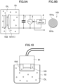
- FIG. 9A is a block diagram illustrating an oil state detection apparatus according to a sixth variation of the first embodiment.
- the coil 1 is a planar coil 101, and a conductor board 102 is provided to face the planar coil 101.
- the conductor board 102 may be configured of, for example, metal such as iron and aluminum, or a dielectric substance.
- the conductor board 102 may not be planar, and may have a mesh shape.
- FIG. 9B is a plan view of the planar coil 101.
- the planar coil 101 includes a dielectric substrate 101a made of, for example, FR-4 or fluorine, and a metal foil pattern 101b (a metal pattern) on the dielectric substrate 101a.
- the conductor board 102 is provided to face the planar coil 101. This allows reduction in leakage of magnetic flux of the planar coil 101.
- the planar coil 101 can be made of a printed board and thus can be made with higher accuracy than a winding coil and can be made thin.
- mass production of the planar coil 101 can be achieved at low cost.
- FIG. 10 is a sectional view of the oil state detection apparatus of FIG. 9 .
- the planar coil 101 and the conductor board 102 are unitized in a sensor circuit unit 91 (housing). More specifically, the planar coil 101 is provided on the lower surface of the sensor circuit unit 91 housing the capacitor 2 and the oscillator 3.
- the conductor board 102 is provided in such a way that the conductor board 102 covers the planar coil 101 with a predetermined space therebetween. This allows the same effect as in FIG. 1 to be exhibited.
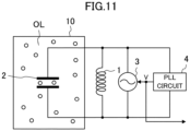
- FIG. 11 is a block diagram illustrating an oil state detection apparatus according to a second embodiment.
- FIG. 11 differs from FIG. 1 in that the capacitor 2 is immersed in the oil OL instead of the coil 1.
- the dielectric constant between electrodes of the capacitor 2 changes with the increase in the amount of the dielectric substances and the conductors contained in the oil OL.
- the capacity value of the capacitor 2 changes.
- the oscillatory frequency of the oscillation circuit changes (see the equation (1)).
- FIG. 12 is a block diagram illustrating an oil state detection apparatus according to a first variation of the second embodiment.
- the oil state detection apparatus according to this variation includes a circuit including a coil 11 (first coil), a capacitor 21 (first capacitor), an oscillator 31, and a PLL circuit 41, and a circuit including a coil 12 (second coil), a capacitor 22 (second capacitor), an oscillator 32, and a PLL circuit 42.
- the oscillator 31 and the PLL circuit 41 correspond to the first detection device
- the oscillator 32 and the PLL circuit 42 correspond to the second detection device.
- the first oscillation circuit is configured of the coil 11 and the capacitor 21
- the second oscillation circuit is configured of the coil 12 and the capacitor 22.
- the coil 11 and the capacitor 22 are immersed in the oil OL.
- voltage values of the tuning voltages V1 and V2 of the PLL circuits 41 and 42 i.e., the oscillatory frequencies of the oscillators 31 and 32, the amount of the magnetic substances, the dielectric substances, and the conductors (the amount of degradation substances) contained in the oil OL can be detected.
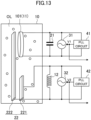
- FIG. 13 is a block diagram illustrating an oil state detection apparatus according to a second variation of the second embodiment.
- FIG. 13 differs from FIG. 12 in that the coil 11 is a planar coil 101.
- an electrode plate 222 faces an electrode plate 221 and the planar coil 101.
- the electrode plates 221 and 222 constitute a capacitor 22.
- the electrode plate 222 is provided to face the planar coil 101. This allows reduction in leakage of magnetic flux of the planar coil 101.
- the planar coil 101 and the electrode plate 222 are disposed to face each other.
- a conductor board 102 may be further provided, which faces the planar coil 101. This makes it possible to reduce adverse effects such as sneaking of the magnetic field and the electric field from the electrode plate 222 to the planar coil 101.
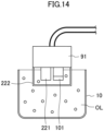
- FIG. 14 is a sectional view of the oil state detection apparatus of FIG. 13 .
- the planar coil 101 and the electrode plates 221 and 222 are unitized in a sensor circuit unit 91 (housing). More specifically, the planar coil 101 and the electrode plate 222 are provided on the lower surface of the sensor circuit unit 91 housing oscillators 31 and 32, a coil 12, and a capacitor 21.
- the electrode plate 222 is provided in such a way that the electrode plate 222 covers the planar coil 101 and the electrode plate 222 with a predetermined space from the electrode plate 222 to the planar coil 101 or the electrode plate 221. This allows the same effect as in FIG. 12 to be exhibited.
- the oscillatory frequency of each oscillation circuit is detected by the detection apparatus (oil state detection apparatus) configured of the oscillator and the PLL circuit.
- the detection apparatus may be configured of components other than the oscillator and the PLL circuit.
- the detection apparatus may be of any configuration as long as the oscillatory frequency of the oscillation circuit is detected.
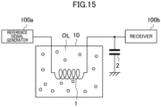
- the detection apparatus may be configured as illustrated in FIG. 15 .
- the detection apparatus includes a coil 1, a capacitor 2, a reference signal generator 100a, and a receiver 100b.
- the reference signal generator 100 outputs a predetermined reference signal (of pulse wave or sin wave) on the coil 1 and the capacitor 2.
- the receiver 100b receives the reference signal output from the reference signal generator 100 via the coil 1 and the capacitor 2.
- the inductance L of the coil 1 varies in accordance with the amount of magnetic substances contained in the oil OL.
- the coil 1 is immersed in the oil OL.
- the capacitor 2 may be immersed in the oil OL to detect the amount of dielectric substances and conductors contained in the oil OL.
- the detection apparatus includes the PLL circuit 4 (41, 42), but is not limited thereto.
- the detection apparatus may include, instead of the PLL circuit 4, an arithmetic circuit configured to analyze a frequency input, and an analysis circuit configured to analyze a frequency by lowering the frequency input.
- the capacitor 2 may be immersed in the oil OL.
- the amount of dielectric substances (degradation substances) contained in the oil OL can be also detected with the advantageous effect of the variation.
- the coil 1 may include a plurality of coils whose inductance values differ from each other and be switchable between the plurality of coils. This configuration can provide a wider detectable range of the amount of dielectric substances and conductors. In such a case, the coil 1 may be a variable coil which can change the inductance value.
- each detection apparatus is provided with a coil 1 (11, 12) and a capacitor 2 (21, 22), but the present disclosure is not limited to such configurations.
- the coil 1 (11, 12) may be a semiconductor provided on a circuit board in the detection apparatus, or may be a coil component of wiring.
- the capacitor 2 (21, 22) may be a semiconductor provided on a circuit board in the detection apparatus, or may be a wiring capacity. That is, the coil 1 (11, 12) and the capacitor 2 (21, 22) do not need to be provided as individual components.
- the coil 1 (11, 12), the capacitor 2 (21, 22), and the oscillator 3 (31, 32) are connected in parallel.
- this is a mere example of the circuit configuration in the detection apparatus, and the detection apparatus may have any circuit configuration as long as the constituent elements described above are included.
- the coil 1 (11, 12), the capacitor 2 (21, 22), and the oscillator 3 (31, 32) may be connected in series.
- the oil state detection apparatus of the present disclosure is applicable to detect the amount of degradation substances such as magnetic substances and dielectric substances contained in oil used as lubricant in construction machinery and vehicles.
Landscapes
- Chemical & Material Sciences (AREA)
- Health & Medical Sciences (AREA)
- Life Sciences & Earth Sciences (AREA)
- General Health & Medical Sciences (AREA)
- Immunology (AREA)
- Pathology (AREA)
- Analytical Chemistry (AREA)
- Biochemistry (AREA)
- Chemical Kinetics & Catalysis (AREA)
- General Physics & Mathematics (AREA)
- Physics & Mathematics (AREA)
- Electrochemistry (AREA)
- Engineering & Computer Science (AREA)
- General Chemical & Material Sciences (AREA)
- Oil, Petroleum & Natural Gas (AREA)
- Food Science & Technology (AREA)
- Medicinal Chemistry (AREA)
- Investigating Or Analyzing Materials By The Use Of Electric Means (AREA)
Applications Claiming Priority (1)
| Application Number | Priority Date | Filing Date | Title |
|---|---|---|---|
| JP2021197792A JP2023083848A (ja) | 2021-12-06 | 2021-12-06 | オイル状態検出装置 |
Publications (3)
| Publication Number | Publication Date |
|---|---|
| EP4191243A2 true EP4191243A2 (fr) | 2023-06-07 |
| EP4191243A3 EP4191243A3 (fr) | 2023-08-23 |
| EP4191243B1 EP4191243B1 (fr) | 2026-04-29 |
Family
ID=84389078
Family Applications (1)
| Application Number | Title | Priority Date | Filing Date |
|---|---|---|---|
| EP22211434.0A Active EP4191243B1 (fr) | 2021-12-06 | 2022-12-05 | Appareil de détection d'état d'huile |
Country Status (3)
| Country | Link |
|---|---|
| US (1) | US20230175994A1 (fr) |
| EP (1) | EP4191243B1 (fr) |
| JP (1) | JP2023083848A (fr) |
Families Citing this family (1)
| Publication number | Priority date | Publication date | Assignee | Title |
|---|---|---|---|---|
| JP2024107633A (ja) * | 2023-01-30 | 2024-08-09 | 株式会社Pillar | オイル状態検出装置 |
Citations (2)
| Publication number | Priority date | Publication date | Assignee | Title |
|---|---|---|---|---|
| JPH0434414U (fr) | 1990-07-20 | 1992-03-23 | ||
| JP2003114206A (ja) | 2001-10-03 | 2003-04-18 | Suzuki Motor Corp | エンジン油の劣化判定方法およびその装置 |
Family Cites Families (26)
| Publication number | Priority date | Publication date | Assignee | Title |
|---|---|---|---|---|
| GB2087564B (en) * | 1980-11-14 | 1984-06-13 | Redland Automation Ltd | Object detector |
| US5268646A (en) * | 1988-04-13 | 1993-12-07 | University Of California Patent, Trademark & Copyright Office | Apparatus for characterizing conductivity of superconducting materials |
| JPH0697246B2 (ja) * | 1991-07-25 | 1994-11-30 | 株式会社ジャルコ | Pll回路を用いた浮遊容量の変化検出方法 |
| KR960010689B1 (ko) * | 1991-08-28 | 1996-08-07 | 미쓰비시덴키 가부시키가이샤 | 연료의 유전율 검지센서 |
| JP3296657B2 (ja) * | 1994-03-25 | 2002-07-02 | 東洋アルミニウム株式会社 | 共鳴ラベル |
| JP3126872B2 (ja) * | 1994-05-12 | 2001-01-22 | 三菱電機株式会社 | 燃料の混合比率検知装置 |
| GB9417763D0 (en) * | 1994-08-31 | 1994-10-19 | Univ Edinburgh | Debris monitoring transducer |
| US5604441A (en) * | 1995-03-14 | 1997-02-18 | Detroit Diesel Corporation | In-situ oil analyzer and methods of using same, particularly for continuous on-board analysis of diesel engine lubrication systems |
| JP3111874B2 (ja) * | 1995-12-19 | 2000-11-27 | 松下電器産業株式会社 | 高周波装置 |
| JPH09229747A (ja) * | 1996-02-27 | 1997-09-05 | Tatsuta Electric Wire & Cable Co Ltd | 管路内の移送物質検知装置 |
| US5656767A (en) * | 1996-03-08 | 1997-08-12 | Computational Systems, Inc. | Automatic determination of moisture content and lubricant type |
| JPH10260742A (ja) * | 1997-03-19 | 1998-09-29 | Advantest Corp | 精密電圧発生装置 |
| JP2002290233A (ja) * | 2001-03-27 | 2002-10-04 | Fujitsu Ltd | Pll回路のモード切替方法及びpll回路のモード制御回路 |
| US6867603B2 (en) * | 2002-12-04 | 2005-03-15 | Delphi Technologies, Inc. | Method for measuring high frequency resistance in diesel engine lubrication oil |
| JP3682460B1 (ja) * | 2004-04-09 | 2005-08-10 | 株式会社ディーゼルユナイテッド | 運動機関 |
| GB0410976D0 (en) * | 2004-05-17 | 2004-06-16 | Randox Lab Ltd | Magnetic particle detector system |
| DE102006018964A1 (de) * | 2006-04-19 | 2007-10-25 | Argo-Hytos Gmbh | Verfahren und Sensorvorrichtung zur Bestimmung der Partikelzahl in einem Ölvolumen |
| US10996210B2 (en) * | 2018-01-02 | 2021-05-04 | Transportation Ip Holdings, Llc | Vehicle system with sensor probe assembly for monitoring oil health |
| US10911160B2 (en) * | 2014-10-08 | 2021-02-02 | Rfmicron, Inc. | Wireless sensor with oppositely positioned antenna and sensing circuitry |
| JP6397395B2 (ja) * | 2014-12-30 | 2018-09-26 | ゼネラル・エレクトリック・カンパニイ | 検出方法およびシステム |
| JP2018105759A (ja) * | 2016-12-27 | 2018-07-05 | 日立金属株式会社 | 透磁率センサ及び透磁率検出方法 |
| JP2018155504A (ja) * | 2017-03-15 | 2018-10-04 | 日立金属株式会社 | 誘電率センサ及び誘電率検出方法 |
| JP6950620B2 (ja) * | 2018-05-16 | 2021-10-13 | 株式会社オートネットワーク技術研究所 | ノイズフィルタ |
| CN110133062A (zh) * | 2019-06-06 | 2019-08-16 | 吉林省百利生物科技有限公司 | 一种月见草油氧化稳定性的检测方法 |
| CN112542993A (zh) * | 2019-09-23 | 2021-03-23 | 中兴通讯股份有限公司 | 谐振电路、频偏控制方法、通信设备及存储介质 |
| US11374580B2 (en) * | 2020-07-30 | 2022-06-28 | Stmicroelectronics International N.V. | Charge pump phase locked loop with low controlled oscillator gain |
-
2021
- 2021-12-06 JP JP2021197792A patent/JP2023083848A/ja active Pending
-
2022
- 2022-12-05 EP EP22211434.0A patent/EP4191243B1/fr active Active
- 2022-12-05 US US18/075,260 patent/US20230175994A1/en active Pending
Patent Citations (2)
| Publication number | Priority date | Publication date | Assignee | Title |
|---|---|---|---|---|
| JPH0434414U (fr) | 1990-07-20 | 1992-03-23 | ||
| JP2003114206A (ja) | 2001-10-03 | 2003-04-18 | Suzuki Motor Corp | エンジン油の劣化判定方法およびその装置 |
Also Published As
| Publication number | Publication date |
|---|---|
| JP2023083848A (ja) | 2023-06-16 |
| EP4191243A3 (fr) | 2023-08-23 |
| EP4191243B1 (fr) | 2026-04-29 |
| US20230175994A1 (en) | 2023-06-08 |
Similar Documents
| Publication | Publication Date | Title |
|---|---|---|
| US8860401B2 (en) | Sensor system and method | |
| JPH1056329A (ja) | 周波数制御発振器 | |
| JPH04230599A (ja) | 測定値検出および伝送装置 | |
| EP4191243B1 (fr) | Appareil de détection d'état d'huile | |
| JP2013167651A (ja) | 静電容量式液面レベルセンサ | |
| JPH07306172A (ja) | 燃料の混合比率検知装置 | |
| EP2551643A1 (fr) | Circuit de mesure capacitif insensible aux interférences à haute fréquence | |
| JPH08278336A (ja) | 静電センサ装置 | |
| JP6233641B2 (ja) | 位置センサ | |
| JP5863395B2 (ja) | 発振器 | |
| US20230152346A1 (en) | Capacitance sensing method and assembly | |
| US10866133B2 (en) | Capacitive limit level switch | |
| US9083357B2 (en) | Frequency locking system | |
| JP2005121428A (ja) | 液体濃度センサ | |
| EP3907891B1 (fr) | Dispositif et procédé de mesure | |
| US6590401B1 (en) | Capacitive proximity switch for evaluating minor changes in capacitance and method therefor | |
| JPS627961B2 (fr) | ||
| CN2429839Y (zh) | 无移动部件差分电容式电场仪 | |
| RU2042929C1 (ru) | Емкостный измеритель уровня | |
| Elton | Analyzation of the resistor-inductor-capacitor circuit | |
| US20240255488A1 (en) | Oil state detection apparatus | |
| JP5557181B2 (ja) | 同期検波回路、フラックスゲートセンサ、及びfm復調装置 | |
| JP5861221B2 (ja) | 圧電振動回路 | |
| EP4563993A1 (fr) | Dispositif de détection de caractéristique de fluide | |
| US20250251358A1 (en) | Oil state detection apparatus |
Legal Events
| Date | Code | Title | Description |
|---|---|---|---|
| PUAI | Public reference made under article 153(3) epc to a published international application that has entered the european phase |
Free format text: ORIGINAL CODE: 0009012 |
|
| STAA | Information on the status of an ep patent application or granted ep patent |
Free format text: STATUS: THE APPLICATION HAS BEEN PUBLISHED |
|
| AK | Designated contracting states |
Kind code of ref document: A2 Designated state(s): AL AT BE BG CH CY CZ DE DK EE ES FI FR GB GR HR HU IE IS IT LI LT LU LV MC ME MK MT NL NO PL PT RO RS SE SI SK SM TR |
|
| PUAL | Search report despatched |
Free format text: ORIGINAL CODE: 0009013 |
|
| AK | Designated contracting states |
Kind code of ref document: A3 Designated state(s): AL AT BE BG CH CY CZ DE DK EE ES FI FR GB GR HR HU IE IS IT LI LT LU LV MC ME MK MT NL NO PL PT RO RS SE SI SK SM TR |
|
| RIC1 | Information provided on ipc code assigned before grant |
Ipc: G01R 23/00 20060101ALI20230714BHEP Ipc: G01N 27/22 20060101ALI20230714BHEP Ipc: G01N 27/02 20060101ALI20230714BHEP Ipc: G01N 33/28 20060101AFI20230714BHEP |
|
| STAA | Information on the status of an ep patent application or granted ep patent |
Free format text: STATUS: REQUEST FOR EXAMINATION WAS MADE |
|
| 17P | Request for examination filed |
Effective date: 20240209 |
|
| RBV | Designated contracting states (corrected) |
Designated state(s): AL AT BE BG CH CY CZ DE DK EE ES FI FR GB GR HR HU IE IS IT LI LT LU LV MC ME MK MT NL NO PL PT RO RS SE SI SK SM TR |
|
| STAA | Information on the status of an ep patent application or granted ep patent |
Free format text: STATUS: EXAMINATION IS IN PROGRESS |
|
| 17Q | First examination report despatched |
Effective date: 20240412 |
|
| GRAP | Despatch of communication of intention to grant a patent |
Free format text: ORIGINAL CODE: EPIDOSNIGR1 |
|
| STAA | Information on the status of an ep patent application or granted ep patent |
Free format text: STATUS: GRANT OF PATENT IS INTENDED |
|
| INTG | Intention to grant announced |
Effective date: 20251105 |
|
| GRAS | Grant fee paid |
Free format text: ORIGINAL CODE: EPIDOSNIGR3 |
|
| GRAA | (expected) grant |
Free format text: ORIGINAL CODE: 0009210 |
|
| STAA | Information on the status of an ep patent application or granted ep patent |
Free format text: STATUS: THE PATENT HAS BEEN GRANTED |
|
| AK | Designated contracting states |
Kind code of ref document: B1 Designated state(s): AL AT BE BG CH CY CZ DE DK EE ES FI FR GB GR HR HU IE IS IT LI LT LU LV MC ME MK MT NL NO PL PT RO RS SE SI SK SM TR |
|
| REG | Reference to a national code |
Ref country code: CH Ref legal event code: F10 Free format text: ST27 STATUS EVENT CODE: U-0-0-F10-F00 (AS PROVIDED BY THE NATIONAL OFFICE) Effective date: 20260429 Ref country code: GB Ref legal event code: FG4D |