EP4191268A1 - Kalibrierungssystem und -verfahren für magnetometer - Google Patents
Kalibrierungssystem und -verfahren für magnetometer Download PDFInfo
- Publication number
- EP4191268A1 EP4191268A1 EP21849544.8A EP21849544A EP4191268A1 EP 4191268 A1 EP4191268 A1 EP 4191268A1 EP 21849544 A EP21849544 A EP 21849544A EP 4191268 A1 EP4191268 A1 EP 4191268A1
- Authority
- EP
- European Patent Office
- Prior art keywords
- magnetometers
- magnetic field
- calibration
- values
- magnetometer
- Prior art date
- Legal status (The legal status is an assumption and is not a legal conclusion. Google has not performed a legal analysis and makes no representation as to the accuracy of the status listed.)
- Pending
Links
- 238000000034 method Methods 0.000 title claims abstract description 76
- 238000001514 detection method Methods 0.000 claims abstract description 122
- 238000009826 distribution Methods 0.000 claims abstract description 60
- 238000004364 calculation method Methods 0.000 claims abstract description 43
- 239000013598 vector Substances 0.000 claims abstract description 36
- 238000005259 measurement Methods 0.000 claims description 28
- 230000008569 process Effects 0.000 claims description 21
- 238000007689 inspection Methods 0.000 claims description 11
- 238000004422 calculation algorithm Methods 0.000 claims description 5
- 238000010586 diagram Methods 0.000 description 18
- 230000008859 change Effects 0.000 description 9
- 238000005086 pumping Methods 0.000 description 6
- 230000000694 effects Effects 0.000 description 5
- 238000012986 modification Methods 0.000 description 4
- 230000004048 modification Effects 0.000 description 4
- 230000002159 abnormal effect Effects 0.000 description 3
- 210000004556 brain Anatomy 0.000 description 3
- 230000008901 benefit Effects 0.000 description 2
- 238000005516 engineering process Methods 0.000 description 2
- 230000005284 excitation Effects 0.000 description 2
- 238000002582 magnetoencephalography Methods 0.000 description 2
- 238000012423 maintenance Methods 0.000 description 2
- 210000001015 abdomen Anatomy 0.000 description 1
- 230000003044 adaptive effect Effects 0.000 description 1
- 229910010293 ceramic material Inorganic materials 0.000 description 1
- 238000006243 chemical reaction Methods 0.000 description 1
- 238000004891 communication Methods 0.000 description 1
- 238000005094 computer simulation Methods 0.000 description 1
- 238000001816 cooling Methods 0.000 description 1
- 230000003247 decreasing effect Effects 0.000 description 1
- 230000007613 environmental effect Effects 0.000 description 1
- 239000000284 extract Substances 0.000 description 1
- 230000004886 head movement Effects 0.000 description 1
- 229910052734 helium Inorganic materials 0.000 description 1
- 239000001307 helium Substances 0.000 description 1
- SWQJXJOGLNCZEY-UHFFFAOYSA-N helium atom Chemical compound [He] SWQJXJOGLNCZEY-UHFFFAOYSA-N 0.000 description 1
- 239000007788 liquid Substances 0.000 description 1
- 238000004519 manufacturing process Methods 0.000 description 1
- 239000000463 material Substances 0.000 description 1
- 230000035699 permeability Effects 0.000 description 1
- 230000010287 polarization Effects 0.000 description 1
- 239000011347 resin Substances 0.000 description 1
- 229920005989 resin Polymers 0.000 description 1
- 230000004044 response Effects 0.000 description 1
- 239000004065 semiconductor Substances 0.000 description 1
- 230000035945 sensitivity Effects 0.000 description 1
- 238000004088 simulation Methods 0.000 description 1
- 238000012360 testing method Methods 0.000 description 1
- 238000009827 uniform distribution Methods 0.000 description 1
Images




Classifications
-
- G—PHYSICS
- G01—MEASURING; TESTING
- G01R—MEASURING ELECTRIC VARIABLES; MEASURING MAGNETIC VARIABLES
- G01R35/00—Testing or calibrating of apparatus covered by the other groups of this subclass
- G01R35/005—Calibrating; Standards or reference devices, e.g. voltage or resistance standards, "golden" references
-
- A—HUMAN NECESSITIES
- A61—MEDICAL OR VETERINARY SCIENCE; HYGIENE
- A61B—DIAGNOSIS; SURGERY; IDENTIFICATION
- A61B5/00—Measuring for diagnostic purposes; Identification of persons
- A61B5/68—Arrangements of detecting, measuring or recording means, e.g. sensors, in relation to patient
- A61B5/6801—Arrangements of detecting, measuring or recording means, e.g. sensors, in relation to patient specially adapted to be attached to or worn on the body surface
- A61B5/6802—Sensor mounted on worn items
- A61B5/6803—Head-worn items, e.g. helmets, masks, headphones or goggles
-
- G—PHYSICS
- G01—MEASURING; TESTING
- G01R—MEASURING ELECTRIC VARIABLES; MEASURING MAGNETIC VARIABLES
- G01R33/00—Arrangements or instruments for measuring magnetic variables
- G01R33/0017—Means for compensating offset magnetic fields or the magnetic flux to be measured; Means for generating calibration magnetic fields
-
- G—PHYSICS
- G01—MEASURING; TESTING
- G01R—MEASURING ELECTRIC VARIABLES; MEASURING MAGNETIC VARIABLES
- G01R33/00—Arrangements or instruments for measuring magnetic variables
- G01R33/0023—Electronic aspects, e.g. circuits for stimulation, evaluation, control; Treating the measured signals; calibration
- G01R33/0035—Calibration of single magnetic sensors, e.g. integrated calibration
-
- G—PHYSICS
- G01—MEASURING; TESTING
- G01R—MEASURING ELECTRIC VARIABLES; MEASURING MAGNETIC VARIABLES
- G01R33/00—Arrangements or instruments for measuring magnetic variables
- G01R33/0094—Sensor arrays
-
- G—PHYSICS
- G01—MEASURING; TESTING
- G01R—MEASURING ELECTRIC VARIABLES; MEASURING MAGNETIC VARIABLES
- G01R33/00—Arrangements or instruments for measuring magnetic variables
- G01R33/20—Arrangements or instruments for measuring magnetic variables involving magnetic resonance
- G01R33/24—Arrangements or instruments for measuring magnetic variables involving magnetic resonance for measuring direction or magnitude of magnetic fields or magnetic flux
- G01R33/26—Arrangements or instruments for measuring magnetic variables involving magnetic resonance for measuring direction or magnitude of magnetic fields or magnetic flux using optical pumping
-
- A—HUMAN NECESSITIES
- A61—MEDICAL OR VETERINARY SCIENCE; HYGIENE
- A61B—DIAGNOSIS; SURGERY; IDENTIFICATION
- A61B5/00—Measuring for diagnostic purposes; Identification of persons
- A61B5/24—Detecting, measuring or recording bioelectric or biomagnetic signals of the body or parts thereof
- A61B5/242—Detecting biomagnetic fields, e.g. magnetic fields produced by bioelectric currents
- A61B5/245—Detecting biomagnetic fields, e.g. magnetic fields produced by bioelectric currents specially adapted for magnetoencephalographic [MEG] signals
-
- G—PHYSICS
- G01—MEASURING; TESTING
- G01R—MEASURING ELECTRIC VARIABLES; MEASURING MAGNETIC VARIABLES
- G01R33/00—Arrangements or instruments for measuring magnetic variables
- G01R33/0023—Electronic aspects, e.g. circuits for stimulation, evaluation, control; Treating the measured signals; calibration
- G01R33/0041—Electronic aspects, e.g. circuits for stimulation, evaluation, control; Treating the measured signals; calibration using feed-back or modulation techniques
Definitions
- the present invention relates to a calibration system and method for magnetometers, a magnetic detection system and a magnetic detection method.
- the present invention further relates to a magnetometer holder
- the magnetic detector of MEG technology with superconducting quantum interference device as the core device needs to have its detector gain value detected and be calibrated periodically (for example, by placing a model that generates known magnetic field intensity).
- SQUID superconducting quantum interference device
- the measurement accuracy of the new optical-pumping atomic magnetometer based on spin-exchange relaxation free effect reaches or even exceeds that of the SQUID magnetometer. Also, it can work in an environment not of ultra-low temperature, and without the need for liquid helium cooling. It is small in volume and light in weight, and its low-cost mass production can be realized through semiconductor technology. Because a magnetic field intensity detected by a magnetometer based on SERF effect is calculated through a polarized beam intensity or a polarization angle detected by a photoelectric sensor, in the field of weak magnetic detection based on the atomic magnetometer, in order to obtain accurate detection results, it is necessary to gauge and calibrate the detection gain value of the detector (magnetometer).
- SERF spin-exchange relaxation free effect
- the present invention provides a calibration system and method for magnetometers, which perform calibration using magnetic field signal sources that can act on all detectors simultaneously, and which carry out coordinated calibration of multiple detectors with said signal sources as the reference signal sources.
- the calibration system and method can continuously calibrate gain values of the detectors in a recording process, so as to obtain accurate multi-detector magnetic field recording and tracing and positioning results.
- An embodiment of the present invention provides a calibration system for magnetometers, comprising magnetometers configured to measure a magnetic field to be measured; a magnetometer holder, the magnetometers being fixedly mounted on the magnetometer holder, so that spatial positions and orientations of the magnetometers are known; at least one magnetic field generating device for generating a calibration magnetic field distribution in the space to be measured, the position of the at least one magnetic field generating device being fixed relative to the magnetometers; and a calculation device configured to calculate the magnitudes of magnetic field vectors at the positions of the magnetometers according to the calibration magnetic field distribution generated by the at least one magnetic field generating device in the space to be measured, receive magnitudes of the magnetic field vectors measured by the magnetometers from the magnetometers, and calculate detection gain values of the magnetometers based on the calculated magnitudes of the magnetic field vectors and the measured magnitudes of the magnetic field vectors.
- An embodiment of the present invention provides a calibration method for magnetometers, comprising: providing magnetometers mounted on a magnetometer holder, the magnetometers being configured to measure a magnitude of a magnetic field at positions of the magnetometers as measured values of the magnetometers; fixing positions of at least one magnetic field generating device relative to the magnetometers, the at least one magnetic field generating device being configured to generate a calibration magnetic field distribution; determining spatial positions and orientations of the magnetometers, and calculating calibration actual values of the magnetic field at the positions of the magnetometers based on the spatial positions and orientations of the magnetometers and the calibration magnetic field distribution; measuring the magnetic field at the positions of the magnetometers to obtain calibration measured values of the magnetic field; calculating detection gain values of the magnetometers based on the calibration measured values and the calibration actual values.
- An embodiment of the present invention provides a calibration method for magnetometers, comprising: providing magnetometers mounted on a magnetometer holder, the magnetometers being configured to measure a magnitude of a magnetic field at positions of the magnetometers as measured values of the magnetometers; providing a plurality of magnetic field generating devices, at least one part of the magnetic field generating devices among the plurality of magnetic field generating devices being fixedly disposed on the magnetometers, and the at least one part of the magnetic field generating devices being configured to generate calibration magnetic fields; measuring the calibration magnetic fields by the magnetometers to obtain calibration measured values of the calibration magnetic fields; calculating detection gain values of the magnetometers based on the calibration magnetic fields and the calibration measured values; generating magnetic fields that are fixed or regularly changing with known parameters by another part of the magnetic field generating devices located on the magnetometer holder, the magnetic fields generated being measured by the magnetometers with their gain calibrated to obtain measured values, and calibrating gain values of the magnetometers through the measured values and the changes thereof during a recording process.
- the magnetic fields
- the embodiment of the present invention provides a magnetic detection system, comprising a magnetometer holder; magnetometers, the magnetometers being mounted on the magnetometer holder and measuring magnitudes of magnetic field vectors at their positions as measured values of the magnetometers; magnetic field generating devices, the magnetic field generating devices being disposed at predetermined positions and generating calibration magnetic field distributions; and a calculation device configured to calculate calibration actual values of the magnetic field vectors at the positions of the magnetometers based on the spatial positions and orientations of the magnetometers and the calibration magnetic field distributions, receive calibration measured values of the magnetic field vectors obtained by the magnetometers, and compare the calibration actual values with the calibration measured values to calculate detection gain values of the magnetometers.
- An embodiment of the present invention relates to a magnetic detection system, comprising a magnetometer holder; magnetometers, the magnetometers being mounted on the magnetometer holder and measuring the magnitudes of magnetic field vectors at their positions as measured values of the magnetometers; first magnetic field generating devices, the first magnetic field generating devices being disposed at predetermined positions and generating calibration magnetic fields; and a calculation device configured to receive calibration measured values of the calibration magnetic fields obtained by the magnetometers and calculate detection gain values of the magnetometers based on the calibration magnetic fields and the calibration measured values.
- An embodiment of the present invention provides a magnetic detection method, comprising: providing magnetometers, the magnetometers being mounted on a magnetometer holder and measuring magnitudes of magnetic field vectors at their positions as measured values of the magnetometers; obtaining detection gain values of the magnetometers using an calibration method as described above; measuring a magnetic field to be measured by the magnetometers; and multiplying measurement results of the magnetometers by the detection gain values to obtain actual values of the magnetic field to be measured.
- An embodiment of the present invention provides a magnetometer holder, comprising mounting parts for mounting magnetometers; and at least one magnetic field generating device having the position fixed relative to the magnetometers and being used to generate a calibration magnetic field.
- magnetometer As the SERF effect-based optical-pumping atomic magnetometer (hereinafter referred to as "magnetometer”) conducts magnetic measurement by using the atomic spin effect in a weak magnetic field, and its detection process is related to the influence of the external magnetic field, the gain value of the detector is not only related to the hardware and control parameters of the detector itself, but also affected by a net magnetic field where the detector is located. A magnetic field even in the insensitive direction of the detector, such as along the incident direction of the detection beam, would affect the detection gain of the detector in the sensitive direction. This characteristic is quite different from a traditional SQUID sensitive detector whose gain value is basically stable under different external magnetic fields.
- the calibration methods used for a traditional SQUID detector array such as periodically (every power-on test, every warm-up maintenance or every equipment routine maintenance cycle) placing a model with known magnetic field intensity to detect and calibrate the detector gain value, are not suitable for optical-pumping atomic magnetometers.
- an existing optical-pumping atomic magnetometer uses a coil to generate a magnetic field with a specific intensity at a position close to the air chamber in each detector during the start-up of the detector, so as to calibrate the gain of the detector. For a single detector, this method is effective and feasible. For a detector array composed of multiple detectors, the magnetic fields generated by the calibration coils will cause crosstalk between the detectors. When one detector is calibrated, the magnetic field generated by it will affect other adjacent detectors.
- the existing device cannot conduct calibration simultaneously on all detectors, and the calibration can only be conducted by calibrating each detector in sequence or by calibrating detectors at a certain distance, i.e., calibration at intervals. This not only greatly prolongs the time required for calibration, but also makes it impossible to calibrate all detectors accurately when the external magnetic field changes.
- the multi-detector system composed of existing detectors cannot carry out continuous calibration or continuous calibration with a certain interval, and it is difficult to conduct accurate multi-detector simultaneous recording and signal tracing and positioning.
- the present invention uses a calibration system and method based on external magnetic field signal sources to perform coordinated calibration of the multiple detectors, and the signal sources can be used as reference signal sources to continuously calibrate gain values of the detectors during the recording process, so as to obtain accurate multi-detector magnetic field recording results.
- optical-pumping atomic magnetometer refers to an optical-pumping atomic magnetometer based on spin-exchange relaxation free effect (SERF).
- SERF spin-exchange relaxation free effect
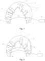
- Fig. 1 shows a schematic diagram of a calibration system according to an embodiment of the present invention.
- Fig. 2 shows a schematic diagram of a calibration system according to another embodiment of the present invention.
- Fig. 3 shows a schematic diagram of a calibration system according to yet another embodiment of the present invention.
- Fig. 4 shows a schematic diagram of a calibration system according to a variant embodiment of the present invention.
- An embodiment of the present invention provides a calibration system for magnetometers, comprising: magnetometers configured to measure a magnetic field to be measured; a magnetometer holder, the magnetometers being mounted on the magnetometer holder; at least one magnetic field generating device having the position fixed relative to the magnetometers and being used to generate a calibration magnetic field; and a calculation device used for obtaining measurement results of the magnetometers.
- the magnetometers are configured to measure the calibration magnetic field generated by the at least one magnetic field generating device, and the calculation device calculates detection gain values of the magnetometers based on the measurement results by the magnetometers.
- the at least one magnetic field generating device may be disposed on at least one of the magnetometer holder, the space to be measured, or the magnetometers.
- selection can be made according to requirements. No matter where the magnetic field generating devices are located, the relative spatial positions and orientations of the magnetic field generating devices and all magnetometers are fixed and known, or can be gauged continuously so as to be known.
- the calibration magnetic fields generated by the magnetic field generating devices are known, so the magnetic field distributions of the calibration magnetic fields at positions where the magnetometers are located are known, and the detection gain values of the magnetometers can be calculated based on measurement results by the magnetometer and the magnetic field distributions.
- the calibration system of the present invention has the advantage that it will not cause crosstalk with the existing magnetometers during calibration, thus not affecting the work of other detectors.
- the calibration system of the present invention can expand the dynamic range of detection of the magnetometers to the nonlinear range of the detectors without sacrificing the sensitivity, thus expanding the detection range.
- the calibration system includes magnetometers 1, a magnetometer holder 2, at least one magnetic field generating device 3 and a calculation device 4.
- the magnetic field generating devices 3 may be configured to generate known or preset calibration magnetic field distributions, which refer to magnetic field distributions that can be calculated according to the input of the magnetic field generating devices 3 or other parameters or can be obtained by other means, and the magnetic field distributions are used to calibrate the detection gain values of the magnetometers 1. Through the magnetic field distributions, the magnitudes of magnetic field vectors at certain spatial positions and orientations in the magnetic field distributions can be obtained.
- the magnetometers 1 are configured to measure a magnetic field to be measured in a space to be measured, such as a brain magnetic signal of a subject.
- a magnetometer holder 2 is in the form of a helmet, which can be fixedly disposed relative to a space to be measured (e.g., the head of a subject), and includes at least one mounting part (not shown) with a predetermined orientation, allowing the magnetometers 1 to each be disposed on the mounting part in a specific direction at a first depth.
- the magnetometer holder 2 comprises a plurality of mounting parts, and the magnetometers 1 are respectively mounted on each mounting part and fixed relative to the magnetometer holder.
- the spatial position and orientation information of the magnetometer 1 can be determined.
- a magnetometer 1 is fixedly mounted on a magnetometer holder 2, so once the mounting is completed, the relative position and orientation between the magnetometer 1 and the mounting hole can be fixed and determined.
- the mounting parts may include, for example, a detection electrode, through which it can be detected that a mounting hole has been mounted with a magnetometer, as well as the mounting depth of the magnetometer.
- the mounting parts may be provided with a sensor to sense mounting information of the magnetometer (e.g., the mounting depth of the magnetometer), and to sense the identification code of the magnetometer, and also to send the mounting information of the magnetometer, such as the mounting depth of the magnetometer, the identification code of the magnetometer, and specific information of the mounting part on which the magnetometer is mounted (e.g., the spatial orientation of the mounting part) to the calculation device, so that the calculation device can obtain the spatial position and orientation information of the magnetometers.
- the detectors of the magnetometers 1 are vector detectors, and the detected magnetic field information is vector information, which is different from the traditional EEG detection that only detects scalar signals of the electrodes. Therefore, the magnetic field vector information detected by the detectors needs to be measured. Also, the detector of a magnetometer 1 may be arranged to detect the magnetic field intensity along the longitudinal axis direction (length direction) of the magnetometer 1.
- the "space to be measured” described in the present disclosure includes, but is not limited to, the head, abdomen or other body parts of a subject, and other objects the magnetic field intensity of which can be detected. Those skilled in the art can make adaptive selections according to the actual measurement applications, and the present disclosure does not pose limitation on this.
- the calibration system includes a plurality of magnetic field generating devices 3, which are respectively arranged at different spatial positions fixed relative to the magnetometers 1.
- the plurality of magnetic field generating devices 3 can be arranged on at least one of the magnetometer holder 2, the space to be measured or the magnetometers 1.
- the calibration system includes four magnetic field generating devices 3, which are respectively arranged at four different spatial positions on the magnetometer holder 2.
- three of the magnetic field generating devices 3 are located at the third parts of the lower end circumference of the magnetometer holder 2 shown in Fig. 1
- the other magnetic field generating device 3 is located at the top right upper position of the magnetometer holder 2.
- the present disclosure is not limited to this.
- the magnetic field generating devices 3 can also be disposed at other spatial positions on the magnetometer holder 2, as long as their positions and orientations relative to the magnetometers are fixed.
- the number of magnetic field generating devices 3 can also be increased or decreased according to actual requirements.
- the calculation device 4 is connected with the magnetometers 1 and the magnetic field generating devices 3 through wired or wireless communication (shown by dotted lines in the figure). Common calculation devices in the field, including but not limited to a CPU, a DSP, a computer, a workstation, etc., can be adopted for calculation device 4.
- the magnetic field generating devices 3 may be coil loops or dipoles immersed in a conductive solution.
- the magnetic field generating devices 3 are coil loops composed of exciting coils, which can generate spatial magnetic fields when energized, as shown in Fig. 5 . Therefore, the magnetic field distributions of the magnetic field generating devices 3 in space can be calculated according to the current of the coil loops, the size of the coil loops, the number of the coil turns and other parameters, thereby the magnitude and direction of the magnetic field vector at a specific position in the space can be calculated.
- the magnetic field generating devices 3 can also be dipoles immersed in a conductive solution.
- the calibration system may further include a gauging device for gauging the calibration magnetic fields generated by the magnetic field generating devices.
- the gauging device may be disposed on or near the magnetic field generating devices 3 to realize continuous gauging, or it may be separately arranged and conducts gauging for the magnetic field generating devices 3 every time a magnetic field generating device 3 needs to be gauged.
- the frequency ranges of the calibration magnetic fields generated by the magnetic field generating devices 3 are set to be outside the frequency range of the magnetic field to be measured.
- the frequency ranges of the calibration magnetic fields generated by the magnetic field generating devices 3 are higher than the frequency range of the magnetic field to be measured, so that crosstalk in the detection results can be prevented.
- the frequency range of the magnetic field to be measured (such as brain magnetic signal) is 1-80 Hz.
- the frequency ranges of the calibration magnetic field distributions generated by the magnetic field generating devices 3 are in the range of 80 Hz to 200 Hz.
- the frequency ranges of the calibration magnetic fields generated by the magnetic field generating devices 3 may be greater than 80 Hz, such as 80-100 Hz, 80-120Hz, 100-200Hz or greater than 200 Hz.
- the frequency ranges of the calibration magnetic fields generated by the magnetic field generating devices 3 may be smaller than the frequency range of the magnetic field to be measured, for example, less than 40 Hz.
- the frequency of the calibration magnetic field distribution generated by each of the plurality of magnetic field generating devices 3 is different, so different magnetic field generating devices 3 can be distinguished in the frequency domain.
- the calibration system also includes a time domain-frequency domain converter (not shown), which is configured to convert time domain signals measured by the magnetometers into frequency domain signals by Fourier transform or other algorithms, and calculate measured values of target corresponding to the magnetometers through the calibration measured values that correspond to the frequencies of the calibration magnetic fields.
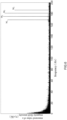
- the time domain signals from the magnetometers, converted by the converter become frequency domain signals as shown in Fig. 6 , for example, and signals with different frequencies each have a peak value in the frequency domain.
- the time domain-frequency domain converter can be an independent conversion chip or an algorithm built into the calculation device.
- Fig. 6 is a diagram showing the distribution of the measured value of a magnetic field intensity, obtained by a calculation device of the embodiment shown in Fig. 1 , in the frequency domain.
- the result in Fig. 6 is the measured value of the magnetic field intensity calculated by the calculation device for one of the magnetometers 1.
- the four magnetic field generating devices 3 are excited at different frequencies, so that the calibration magnetic field generated by each magnetic field generating device 3 has a different frequency, such as 173 Hz, 178 Hz, 183 Hz and 188 Hz.
- the magnetic field intensity generated by the four magnetic field generating devices 3 has four peaks in frequency domain, and the measured values of them are M1, M2, M3 and M4, respectively, as shown in Fig. 6 .
- Different magnetic field generating devices 3 can be distinguished and marked in the frequency domain space through the different calibration magnetic field frequencies, and there will be no interference or crosstalk between them, which is convenient for measurement and calibration operation.
- Fig. 2 shows a schematic diagram of a calibration system according to another embodiment of the present disclosure. Different from the embodiment shown in Fig. 1 , this embodiment adopts larger-sized magnetic field generating devices 31, which can form calibration magnetic fields with more uniform distributions in space, thus facilitating a convenient calibration.
- Fig. 3 shows a schematic diagram of a calibration system according to yet another embodiment of the present disclosure.
- the magnetic field generating devices 32 of this embodiment are fixedly arranged on at least one of the plurality of magnetometers, such as on three magnetometers, as shown in Fig. 3 .
- the magnetic field generating devices can also have other arrangements according to calibration requirements.
- a first magnetic field generating device 33 can be fixedly disposed on each magnetometer 1, and at least one second magnetic field generating device 34, such as two second magnetic field generating devices 34, can further be fixedly disposed on the magnetometer holder 2, as shown in Fig. 4 .
- Fig. 5 shows a schematic diagram of the spatial distributions of the calibration magnetic fields generated by the magnetic field generating devices according to an embodiment of the present invention.
- Fig. 7 shows a flowchart of a calibration method for magnetometers according to an embodiment of the present invention.
- the calibration method includes the following steps:
- step S10 the arrangement of the magnetometers 1 and the magnetometer holder 2 in the embodiment shown in Figs. 1-3 , for example, can be adopted, which will not be described in detail here.
- step S20 the magnetic field generating devices of the previous embodiment can be adopted for the magnetic field generating devices 3.
- the magnetic field generating devices 3 are turned on to generate calibration magnetic fields, which will form spatial magnetic field distributions, as shown in Fig. 5 .
- the parameters of the calibration magnetic field distributions can be obtained by pre-gauging, and the spatial magnetic field distributions of the calibration magnetic fields can be obtained through computational simulation of Maxwell's equations and Jefimenko's equations which are based on Maxwell's equations.
- step S30 as long as the position of any magnetometer 1 in space is known, the magnitude of an actual value M 0 of a calibration magnetic field at the position of this magnetometer 1 can be obtained.
- the spatial positions of the magnetometers 1 can be determined by various methods, which will be further described below.
- step S40 the magnetometer 1 measures the magnitude of magnetic field of a calibration magnetic field at the position of the magnetometer 1, and obtains a measured value of calibration M A .
- step S50 the detection gain value is calculated by the calculation device 4 based on the measured value of calibration M A and the calculated actual value of calibration M 0 .
- This detection gain value can be used to calibrate the difference between the measured value of the magnetometer 1 and the actual value.
- the detection gain value may comprise a detection gain value K of the magnetometer.
- the magnetometer 1 can be calibrated. For example, when the magnetometer 1 is actually working, the signal value of the magnitude of the actual magnetic field can be obtained by multiplying the signal of the magnitude of the magnetic field measured by the magnetometer 1, i.e., the measured value of target, by the detection gain value K.
- the gain response of a detector at different frequencies may be nonlinear, and the gain values for different frequencies can be calculated by pre-calibrated detection gain values.
- Fig. 5 is taken as an example to describe a calibration method of the present disclosure.
- the embodiment shown in Fig. 5 is only an example, and those skilled in the art can make changes and modifications based on the principle of Fig. 5 , the variations and modifications being still within the scope of protection of the present disclosure.
- Fig. 5 shows two magnetometers, a first magnetometer 1 and a second magnetometer 1'.
- the first magnetometer 1 includes a detector 11 accommodated therein
- the second magnetometer 1' includes a detector 11' accommodated therein.
- the detectors 11 and 11' are the components of the magnetometers that actually detect the magnitude of the magnetic field, so positions of the detectors 11 and 11' can be used as positions of the magnetometers for calibration, and the preset magnetic field distribution can also be calculated based on the positions of the detectors 11 and 11'.
- two magnetic field generating devices are shown, namely the first magnetic field generating device 3 and the second magnetic field generating device 3'.
- positions of the two magnetic field generating devices are not limited, and one can refer to the arrangement pattern in the previous embodiment.
- the first magnetic field generating device 3 and the second magnetic field generating device 3' respectively generate calibration magnetic fields, the distributions of which are shown by the magnetic lines of force in Fig. 5 .
- the distributions of the calibration magnetic fields of the first magnetic field generating device 3 and the second magnetic field generating device 3' can be calculated.
- the magnetic field formed by superimposing the calibration magnetic fields generated by the first magnetic field generating device 3 and the second magnetic field generating device 3' can be decomposed into a magnetic field component L 1 along the longitudinal direction of the first magnetic field generating device 3 and a magnetic field component Hi in the transverse direction.
- the magnetic field formed by superimposing the calibration magnetic fields generated by the first magnetic field generating device 3 and the second magnetic field generating device 3' can be decomposed into a magnetic field component L 2 along the longitudinal direction of the second magnetic field generating device 3' and a magnetic field component H 2 in the transverse direction.
- the detector of a magnetometer measures the magnetic field component along the longitudinal direction.
- the present disclosure is not limited to this, and the magnetometer can also be changed in its configuration to measure the magnetic field component in the transverse direction or the overall magnetic field vector.
- the detectors of the magnetometers measure the magnetic field components along the longitudinal directions, that is, corresponding to L 1 and L 2 , respectively. Furthermore, the first magnetic field generating device 3 and the second magnetic field generating device 3' are operated to generate a predetermined magnetic field distribution, and the magnetometers 1 and 1' are used respectively to measure the magnitude of the magnetic field and obtain measured values M 1 and M 2 .
- the multiple gain values are averaged or squared averaged to increase the calibration accuracy.
- the magnetic field generating devices, the detectors or the detector holder may be abnormal, which should be inspected and repaired.
- the calibration method may further include gauging the calibration magnetic fields generated by the magnetic field generating devices using a gauging device.
- the calibration method may further include determining whether the deviation of the gain values of at least one magnetometer among a plurality of magnetometers for different magnetic field generating devices is greater than a threshold value, and when the detection gain value of the at least one magnetometer is greater than a threshold value, replacing the at least one magnetometer or inspecting the magnetic field generating devices.
- the threshold can be set in advance, for example, the threshold is set in the range of ⁇ 1%. If deviation between gain values calculated by all or most of the magnetometers for a certain magnetic field generating device and gain values calculated for other magnetic field generating devices is greater than the threshold, it means that this magnetic field generating device may have failed or moved in position. If deviation of detection gain values of a certain magnetometer for different magnetic field signal sources is greater than the threshold, it means that this magnetometer may have failed or moved in position, and at this time it is necessary to replace this magnetometer or readjust its position.
- the threshold may be between 0.1% and 5%, which is set according to the detectors, the supporting device and different characteristics of the application. It can be understood by those skilled in the art that the threshold value can be 0.1 to 5% or -5% to -0.1%. That is, the threshold represents the maximum value of the degree of deviation, so it can be either positive or negative.
- Fig. 8 shows a flowchart of a calibration method for magnetometers according to another embodiment of the present invention. Different from the embodiment shown in Fig. 7 , this embodiment comprises a plurality of magnetic field generating devices, and comprises the above-mentioned determining and inspection steps.
- a first determining step is performed to determine whether deviation of detection gain values of at least one part of the magnetometers for the frequency of one same calibration magnetic field distribution from those for the frequencies of other calibration magnetic field distributions is greater than a threshold value.
- the at least one part of the magnetometers are at least 80% of the magnetometers, or all of the magnetometers.
- a first inspection operation is performed, such as gauging the magnetic field generating device that generates the calibration magnetic field distribution or replacing the magnetic field generating device. After the first inspection operation, the first determining step is repeated until the deviation of the detection gain values of most magnetometers for the frequency of the calibration magnetic field distribution is less than or equal to the threshold.
- the first determining step is passed, that is, the above-mentioned deviation is less than or equal to the threshold, one can move on to the second determining step to determine whether the deviation of the detection gain values of a magnetometer for different magnetic field generating devices is greater than the threshold.
- the second inspection operation is performed, such as replacing the magnetometer, and the first determining step is repeated until the deviation of the detection gain values for different magnetic field generating devices is less than or equal to the threshold.
- the threshold in the above two determining steps is in the range of 0.1-5%.
- the value of the threshold is 0.1%, 0.5%, 1%, 2% or 5%.
- the normal operation of the magnetic field generating devices and the accuracy of the detection gain values of the magnetometers can be ensured, and the reliability of the system and the accuracy of the measurement results can be improved.
- determining the spatial positions and orientations of the magnetometers comprises determining the spatial positions and orientations of the magnetometers through the mounting positions and orientations of the magnetometers on the magnetometer holder or through photographing positioning markers disposed on the magnetometers by a photogrammetry system.
- a method for continuously calibrating the magnetometers is also provided, which is especially suitable for a case where the magnetometer holder is flexible (e.g., a flexible helmet), but the present invention is not limited to this, and can also be applied to an example of a rigid holder. Sometimes the person wearing the helmet cannot avoid head movement, so that the orientations and positions of the magnetometers will change to some extent.
- the magnetometers can be calibrated at the same time when they are conducting the measurement or at intervals and separated from the measurement.
- the frequencies of the magnetic fields generated by the magnetic field generating devices are different from the frequency of the magnetic field to be measured by the magnetometers, even if the magnetometers are calibrated at the same time of measurement, it is possible, through the difference in frequencies, to extract signals with predetermined frequencies from the measurement results of the magnetometers as measured values.
- the time domain signals measured by the magnetometers are converted into frequency domain signals by Fourier transform or other algorithms with a time domain-frequency domain converter, and the measured values of target corresponding to the detector magnetometers are calculated through the calibration measured values corresponding to the frequencies of the calibration magnetic fields.
- the positions and orientations of the magnetometers can be measured in real time by using a dynamic measurement system (see the applicant's prior application CN201911190087.2 , which is incorporated herein by reference in its entirety).
- the position and orientation information of the magnetometers measured by the dynamic measurement system is input into the calculation device, so that the calculation device, based on the position and orientation information and the parameters of the magnetic field generating devices, calculates the magnitudes of the magnetic field vectors of the magnetic field distributions generated by the magnetic field generating devices at the positions where the magnetometers are located as calibration actual values of the magnetic field, and compares the calibration measured values with the calculated calibration actual values, so as to dynamically calibrate the magnetometers, that is, dynamically adjust the gains of the magnetometers.
- By dynamically adjusting the gain values of the magnetometers and applying the adjusted gain values to the measured values of target by the magnetometers more accurate measurement can be realized.
- Fig. 9 shows a flowchart of a calibration method for magnetometers according to yet another embodiment of the present invention.
- the following will mainly focus on the differences between this embodiment and the previous embodiments, and similar or identical steps and features will be omitted or briefly described.
- the calibration method comprises the following steps:
- this embodiment uses magnetic field generating devices 33 fixedly disposed on the magnetometers to generate the calibration magnetic fields, and the calibration magnetic fields are known. Therefore, there is no need to determine the spatial positions and orientations of the magnetometers, and there is no need to calculate the calibration actual values of the magnetic fields at the positions of the magnetometers based on the spatial positions and orientations of the magnetometers and the calibration magnetic field distributions, thus omitting the steps of determining the spatial positions and orientations of the magnetometers and calculating the spatial magnetic field distributions.
- the magnetometers 1 and the magnetometer holder 2 in step 5110 can be arranged as in the embodiment shown in Fig. 4 , for example, and will not be described in detail here.
- the magnetic field generating devices in the previous embodiment can be adopted as the magnetic field generating devices 33.
- the magnetic field generating devices 33 are turned on to generate calibration magnetic fields. Since the magnetic field generating devices 33 are fixedly disposed on the magnetometers 1, the magnetic fields generated by the magnetic field generating devices 33 at the magnetometers 1 can be considered known.
- the calibration measured values M A of the calibration magnetic fields are measured by the magnetometers 1. The actual values of magnetic field generated by the calibration magnetic fields are given to be M 0 .
- step S140 the calibration gain values K are calculated by the calculation device 4 based on the calibration measured values M A and the actual values of magnetic field M 0 .
- the method of calculating the calibration gain values K and the method of measuring the actual signal values of the magnitudes of the magnetic fields based on the calibration gain values K have been described in the previous embodiment (in the previous embodiment as the detection gain values K), which will not be repeated here.
- each magnetometer 1 may be provided with a magnetic field generating device 33, and in step S140, the calibration gain value K of each magnetometer 1 may be measured and it may be recorded in the calculation device 4.
- the magnetic field generating devices 34 may be disposed on the magnetometer holder 2 or the space to be measured.
- two magnetic field generating devices 34 are fixedly disposed at different positions of the magnetometer holder 2, and the magnetic field generating devices 34 may have the same configuration as the magnetic field generating devices 33.
- the number and positions of the magnetic field generating devices 34 can be selected as required, and the present disclosure is not limited to this.
- step S150 the additional magnetic fields at the positions of the magnetometers 1 are measured by the magnetometers 1 and the measured values of magnetic field M B of the additional magnetic fields are obtained.
- step S160 during the working process of the magnetometers 1, the additional magnetic fields at the positions of the magnetometers 1 are measured by the magnetometers 1 and the measured working values of magnetic field M C of the additional magnetic fields are obtained.
- the magnetic field excitation signals (e.g., excitation current) of the magnetic field generating devices 34 can be set in step S150 to remain unchanged or change with known parameters, the actual values of magnetic field M 1 of the additional magnetic fields can remain unchanged or change with known parameters.
- the detection gain values K' of the magnetometers 1 can be calculated based on the measured values of magnetic field M B and the measured working values of magnetic field M C .
- the detection gain values K' change can be monitored in real time by measuring the additional magnetic fields and obtaining the measured working values of magnetic field Mc of the additional magnetic fields.
- the detection gain values K' of the magnetometers 1 can be calculated by a similar method based on the measured values of magnetic field M B , the parameters of the additional magnetic fields and the measured working values of magnetic field M C , which will not be repeated here.
- the detection gain values K' of the magnetometers 1 are continuously calculated, and whether the deviation between different detection gain values K' are greater than the threshold is determined. If the deviation of the detection gain values K' of the magnetometers are greater than the threshold, an inspection operation is performed.
- the inspection operation related to the above exemplary embodiment aims at checking the causes of the deviation, such as an abnormal magnetometer detection, an abnormal change in the additional magnetic fields or interference by the environmental noise, etc.
- causes of the deviation such as an abnormal magnetometer detection, an abnormal change in the additional magnetic fields or interference by the environmental noise, etc.
- Those skilled in the art can use appropriate inspection operations to eliminate the causes of the deviation, and the present disclosure is not limited on this.
- the value of the threshold is in the range of 0.1-5%.
- the value of the threshold is 0.1%, 0.5%, 1%, 2% or 5%.
- the calibration method may also comprise turning off the magnetic field generating devices 33 fixedly disposed on the magnetometers 1 during the working process of the magnetometers 1.
- the crosstalk between the magnetic fields can be prevented, thus improving the magnetic field detection accuracy of the magnetometers 1, or the devices 33 can be used for other purposes.
- Fig. 10 shows a schematic diagram of a magnetometer holder according to an embodiment of the present invention.
- An embodiment of the present disclosure further provides a magnetometer holder 100 comprising mounting parts 200 and at least one magnetic field generating device 3.
- the mounting parts 200 are used for mounting the magnetometers 1.
- the magnetic field generating devices 3 have the position fixed relative to the magnetometers 1 and are used to generate calibration magnetic fields.
- the magnetometer holder 100 is rigid or flexible.
- the magnetometer holder 100 is a helmet.
- the magnetometer holder 100 is rigid, that is, once worn on the head of a subject, the relative positions of different magnetometers 1 on the magnetometer holder 100 will not easily change.
- the magnetometer holder 100 can be made of nonmagnetic materials, such as photosensitive toughened resin or nano-ceramic materials.
- Fig. 11 shows a schematic block diagram of a magnetic detection system according to an embodiment of the present invention.
- An embodiment of the present invention also provides a magnetic detection system 300 comprising a magnetometer holder 100, magnetometers 1, a measurement system 500, magnetic field generating devices 3 and a calculation device 4.
- the magnetometers 1 is mounted on the magnetometer holder 100 and measure the magnitudes of the magnetic field vectors at the positions of the magnetometers 1.
- the measurement system 500 is configured to measure the spatial positions and orientations of the magnetometers 1 in real time.
- the magnetic field generating devices 3 are disposed at predetermined positions and generates calibration magnetic field distributions.
- the arrangement of the magnetic field generating devices 3 can refer to the description in the previous embodiments, and will not be repeated here.
- the calculation device 4 is configured to calculate the calibration actual values of the magnetic field vectors at the positions of the magnetometers 1 based on the spatial positions and orientations of the magnetometers 1 measured by the measuring system 500 and the calibration magnetic field distributions. Furthermore, the calculation device 4 also receives the calibration measured values of the magnetic field vectors measured by the magnetometers 1, and compares the calibration actual values with the calibration measured values to calculate the detection gain values of the magnetometers.
- the magnetic detection system 300 may further comprise a time domain-frequency domain converter.
- the converter is configured to convert the time domain signals measured by the magnetometers into frequency domain signals through Fourier transform or other algorithms, and calculate the measured values of target corresponding to the magnetometers through the calibration measured values corresponding to the frequencies of the calibration magnetic fields.
- the converter extracts signals with predetermined frequencies from the measurement results measured by the magnetometers as the measured values.
- the frequencies of the calibration magnetic fields can be selected according to the frequencies of the magnetic field distributions generated by the magnetic field generating devices 3, for example, equal to the frequencies of the magnetic field distributions. Also, signals of other frequencies, which are other than the frequencies of the calibration magnetic fields, are output as the measured values of magnetic field to be measured, said other frequencies can for example be in the range of 1-80 Hz. In a case where the target to be measured is the magnetoencephalography of the human brain, the other frequencies may be 1-150 Hz or 1-200 Hz.
- a magnetic detection system which comprises a magnetometer holder, magnetometers, first magnetic field generating devices and a calculation device.
- the first magnetic field generating devices are fixedly disposed on the magnetometers and generate the calibration magnetic fields
- the calculation device is configured to receive the calibration measured values of the calibration magnetic fields obtained by the magnetometers and calculate the calibration gain values of the magnetometers based on the calibration magnetic fields and the calibration measured values.
- the magnetic detection system may further comprise second magnetic field generating devices.
- the second magnetic field generating devices have positions fixed relative to the magnetometers and are configured to generate additional magnetic fields.
- This magnetic detection system is particularly suitable for the calibration method shown in Fig. 9 and its embodiment.
- Fig. 12 shows a flowchart of a magnetic detection method according to an embodiment of the present invention.
- An embodiment of the invention further provides a magnetic detection method, the method comprising the following steps:
- the measured values of target (step S103) and the calibration measured values (step S101) are measured simultaneously, and both of them are used as measurement values of the magnetometers. Further, the measured values of target and the calibration measured values are in different frequency ranges.
- a step S105 is also included.
- the measured values by the magnetometers are divided with respect to frequency in order to obtain the calibration measured values and the measured values of target.
- the magnetic detection can also be carried out continuously and in real time.
- the positions and orientations of the magnetometers are measured in real time, and the information of the positions and orientations of the magnetometers is input into the calculation device, and the calibration actual values of the magnetic field at the positions of the magnetometers are calculated, and the calibration measured values are compared with the calculated calibration actual values, thereby the detection gain values is continuously calculated.
- the measurement results of the magnetometers are multiplied by the detection gain values to obtain the actual values of the magnetic field to be measured in real time.
- the calibration system and method provided by the present invention can effectively prevent the crosstalk between detectors, improve the calibration accuracy, and meanwhile can perform calibration in real time, continuously and cooperatively with multiple detectors, so as to obtain accurate multi-detector magnetic field recording results.
Landscapes
- Physics & Mathematics (AREA)
- General Physics & Mathematics (AREA)
- Condensed Matter Physics & Semiconductors (AREA)
- Health & Medical Sciences (AREA)
- Life Sciences & Earth Sciences (AREA)
- Medical Informatics (AREA)
- General Health & Medical Sciences (AREA)
- Heart & Thoracic Surgery (AREA)
- Engineering & Computer Science (AREA)
- Molecular Biology (AREA)
- Surgery (AREA)
- Animal Behavior & Ethology (AREA)
- Biomedical Technology (AREA)
- Public Health (AREA)
- Veterinary Medicine (AREA)
- Pathology (AREA)
- Biophysics (AREA)
- Measuring Magnetic Variables (AREA)
- Measurement And Recording Of Electrical Phenomena And Electrical Characteristics Of The Living Body (AREA)
Applications Claiming Priority (2)
| Application Number | Priority Date | Filing Date | Title |
|---|---|---|---|
| CN202010753611.9A CN112834973A (zh) | 2020-07-30 | 2020-07-30 | 用于磁力计的校准系统和方法 |
| PCT/CN2021/109654 WO2022022690A1 (zh) | 2020-07-30 | 2021-07-30 | 用于磁力计的校准系统和方法 |
Publications (2)
| Publication Number | Publication Date |
|---|---|
| EP4191268A1 true EP4191268A1 (de) | 2023-06-07 |
| EP4191268A4 EP4191268A4 (de) | 2024-09-11 |
Family
ID=75923227
Family Applications (1)
| Application Number | Title | Priority Date | Filing Date |
|---|---|---|---|
| EP21849544.8A Pending EP4191268A4 (de) | 2020-07-30 | 2021-07-30 | Kalibrierungssystem und -verfahren für magnetometer |
Country Status (4)
| Country | Link |
|---|---|
| US (1) | US12196834B2 (de) |
| EP (1) | EP4191268A4 (de) |
| CN (1) | CN112834973A (de) |
| WO (1) | WO2022022690A1 (de) |
Families Citing this family (9)
| Publication number | Priority date | Publication date | Assignee | Title |
|---|---|---|---|---|
| CN112857325B (zh) | 2019-11-28 | 2025-09-02 | 中科知影(北京)科技有限公司 | 用于磁力计空间定位的系统和方法 |
| CN112834973A (zh) * | 2020-07-30 | 2021-05-25 | 中科知影(北京)科技有限公司 | 用于磁力计的校准系统和方法 |
| CN113520399B (zh) * | 2021-07-12 | 2023-03-14 | 北京航空航天大学 | 一种基于亥姆霍兹线圈阵列的心脏磁场模拟系统 |
| WO2023034918A1 (en) * | 2021-09-01 | 2023-03-09 | FieldLine Inc. | Coregistration of magnetoencephalography (meg) data to anatomical space |
| US12265137B2 (en) * | 2022-11-18 | 2025-04-01 | Allegro Microsystems, Llc | Diagnostic path for gain and offset calibration |
| CN115932677A (zh) * | 2022-12-22 | 2023-04-07 | 中科知影(北京)科技有限公司 | 局部磁场补偿装置、磁场补偿系统和方法 |
| CN116774124B (zh) * | 2023-02-09 | 2024-01-02 | 北京昆迈医疗科技有限公司 | Opm的调试校准方法及装置 |
| CN116869539B (zh) * | 2023-07-06 | 2024-04-19 | 北京未磁科技有限公司 | 用于脑磁系统的校准方法、校准装置以及脑磁系统 |
| CN117031370A (zh) * | 2023-08-04 | 2023-11-10 | 深圳市瓦特源检测研究有限公司 | 磁饱和验证方法 |
Family Cites Families (21)
| Publication number | Priority date | Publication date | Assignee | Title |
|---|---|---|---|---|
| US6543146B2 (en) * | 2000-12-06 | 2003-04-08 | Honeywell International, Inc. | Electronic compass and compensation of large magnetic errors for operation over all orientations |
| CN1202498C (zh) | 2002-11-15 | 2005-05-18 | 清华大学 | 基于近景摄影测量的脑电电极空间定位方法 |
| DE102012208389A1 (de) | 2012-05-18 | 2013-11-21 | Fiagon Gmbh | Registrierverfahren und -vorrichtung für ein Positionserfassungssystem |
| US9846218B2 (en) * | 2012-12-31 | 2017-12-19 | General Electric Company | Calbration of a sensor assembly for use in medical position/orientation tracking |
| CN106597228A (zh) * | 2015-10-14 | 2017-04-26 | 南京智中信息技术有限公司 | 局部放电无线智能监测系统 |
| US10132879B2 (en) * | 2016-05-23 | 2018-11-20 | Allegro Microsystems, Llc | Gain equalization for multiple axis magnetic field sensing |
| JP6548615B2 (ja) * | 2016-08-23 | 2019-07-24 | 富士フイルム株式会社 | 磁場歪み算出装置、方法およびプログラム |
| CN106725342B (zh) * | 2017-01-09 | 2019-08-30 | 上海理工大学 | 基于矢量漩涡光束的脑磁图检测装置 |
| CN206863201U (zh) * | 2017-04-26 | 2018-01-09 | 国网江苏省电力公司检修分公司 | 一种应用于现场的变压器常用试验仪器比对装置 |
| US20180313908A1 (en) * | 2017-04-28 | 2018-11-01 | QuSpin Inc. | System for continuously calibrating a magnetic imaging array |
| US9791536B1 (en) * | 2017-04-28 | 2017-10-17 | QuSpin, Inc. | Mutually calibrated magnetic imaging array |
| EP3467528B1 (de) * | 2017-10-06 | 2020-05-20 | Melexis Technologies NV | Kalibrierung der empfindlichkeitsanpassung eines magnetsensors |
| CN107861091B (zh) * | 2017-10-23 | 2019-12-06 | 国网江西省电力公司电力科学研究院 | 一种基于动态电能校准器的动态性能溯源方法 |
| CN107861084B (zh) * | 2017-11-08 | 2019-11-29 | 歌尔科技有限公司 | 一种磁力计校准方法及装置 |
| CN109270480B (zh) * | 2018-10-15 | 2021-09-03 | 上海华虹宏力半导体制造有限公司 | 检测源监控单元的方法 |
| CN109298365B (zh) * | 2018-11-13 | 2023-09-19 | 中国船舶重工集团公司第七0四研究所 | 三轴磁传感器正交度及增益一致性校准装置及方法 |
| EP3666163B1 (de) * | 2018-12-10 | 2023-02-01 | Max-Planck-Gesellschaft zur Förderung der Wissenschaften e.V. | Verfahren zur gleichzeitigen kalibrierung für ein magnetisches lokalisierungs- und betätigungssystem |
| WO2020145344A1 (ja) * | 2019-01-11 | 2020-07-16 | Tdk株式会社 | 磁場校正装置及びこれを用いた磁気計測装置のキャリブレーション方法 |
| CN211123238U (zh) * | 2019-10-30 | 2020-07-28 | 河南省计量科学研究院 | 电能表双标准校验装置 |
| CN211178436U (zh) | 2019-11-28 | 2020-08-04 | 中科知影(北京)科技有限公司 | 用于磁力计空间定位的系统 |
| CN112834973A (zh) * | 2020-07-30 | 2021-05-25 | 中科知影(北京)科技有限公司 | 用于磁力计的校准系统和方法 |
-
2020
- 2020-07-30 CN CN202010753611.9A patent/CN112834973A/zh active Pending
-
2021
- 2021-07-30 WO PCT/CN2021/109654 patent/WO2022022690A1/zh not_active Ceased
- 2021-07-30 US US18/018,735 patent/US12196834B2/en active Active
- 2021-07-30 EP EP21849544.8A patent/EP4191268A4/de active Pending
Also Published As
| Publication number | Publication date |
|---|---|
| WO2022022690A1 (zh) | 2022-02-03 |
| US20230221394A1 (en) | 2023-07-13 |
| US12196834B2 (en) | 2025-01-14 |
| EP4191268A4 (de) | 2024-09-11 |
| CN112834973A (zh) | 2021-05-25 |
Similar Documents
| Publication | Publication Date | Title |
|---|---|---|
| US12196834B2 (en) | Calibration system and method for magnetometers | |
| US8847586B2 (en) | Inspection apparatus and inspection method of magnetic sensor | |
| Bernieri et al. | Eddy current testing probe based on double-coil excitation and GMR sensor | |
| KR101287426B1 (ko) | 극저자기장 핵자기 공명 물체 식별 방법 및 극저자기장 핵자기 공명 물체 식별 장치 | |
| US11422110B2 (en) | Observation method and observation device | |
| CA2518674C (en) | Method and system for processing a multi-channel measurement of magnetic fields | |
| JP4044658B2 (ja) | 核磁気共鳴装置の作動方法 | |
| WO2018006020A1 (en) | Calibration and monitoring for 3-axis magnetometer arrays of arbitrary geometry | |
| Nurminen et al. | Improving MEG performance with additional tangential sensors | |
| JP2015039635A (ja) | 種々の形式のシムコイルを使用する磁気共鳴トモグラフィシステムの特に患者に適応した静磁場均一化方法 | |
| US10018690B2 (en) | Phantom based MR field mapping of the polarizing magnetic field | |
| JPWO2020145344A1 (ja) | 磁場校正装置及びこれを用いた磁気計測装置のキャリブレーション方法 | |
| US7613578B2 (en) | Method for noninvasive determination of a distribution of electrical current and apparatus for the same | |
| Liu et al. | Nonintrusive current sensing for multicore cables considering inclination with magnetic field measurement | |
| CN115932677A (zh) | 局部磁场补偿装置、磁场补偿系统和方法 | |
| Ilmoniemi | The triangle phantom in magnetoencephalography | |
| JPH11304858A (ja) | 電磁波発生源探査装置およびその探査方法 | |
| US7511485B2 (en) | Magnetic field measurement method and system | |
| Jiang et al. | A novel orthogonal electromagnetic sensing method for metal detection | |
| Hiergeist et al. | A novel test ground for the equipment qualification of magnetic gradient sensors used for unexploded bomb detection | |
| Barrell et al. | Detection and localisation of magnetic objects | |
| US20070132455A1 (en) | Shimming with MRI gradient | |
| Alatawneh et al. | Calibration of the tangential coil sensor for the measurement of core losses in electrical machine laminations | |
| Buranello et al. | Development and implementation of a tomographic system for the quantitative reconstruction of magnetic microparticles based on AC biosusceptometry sensors | |
| Reinbacher-Köstinger et al. | Fast, accurate and reliable identification of hidden conductive objects with deterministic and stochastic methods |
Legal Events
| Date | Code | Title | Description |
|---|---|---|---|
| STAA | Information on the status of an ep patent application or granted ep patent |
Free format text: STATUS: THE INTERNATIONAL PUBLICATION HAS BEEN MADE |
|
| PUAI | Public reference made under article 153(3) epc to a published international application that has entered the european phase |
Free format text: ORIGINAL CODE: 0009012 |
|
| STAA | Information on the status of an ep patent application or granted ep patent |
Free format text: STATUS: REQUEST FOR EXAMINATION WAS MADE |
|
| 17P | Request for examination filed |
Effective date: 20230228 |
|
| AK | Designated contracting states |
Kind code of ref document: A1 Designated state(s): AL AT BE BG CH CY CZ DE DK EE ES FI FR GB GR HR HU IE IS IT LI LT LU LV MC MK MT NL NO PL PT RO RS SE SI SK SM TR |
|
| DAV | Request for validation of the european patent (deleted) | ||
| DAX | Request for extension of the european patent (deleted) | ||
| A4 | Supplementary search report drawn up and despatched |
Effective date: 20240809 |
|
| RIC1 | Information provided on ipc code assigned before grant |
Ipc: G01R 33/26 20060101ALN20240805BHEP Ipc: A61B 5/00 20060101ALI20240805BHEP Ipc: G01R 33/00 20060101ALI20240805BHEP Ipc: G01R 35/00 20060101AFI20240805BHEP |