EP4191321A1 - Architecture d'élément optique diffractif de guide d'ondes pour dispositif de réalité augmentée - Google Patents
Architecture d'élément optique diffractif de guide d'ondes pour dispositif de réalité augmentée Download PDFInfo
- Publication number
- EP4191321A1 EP4191321A1 EP21878070.8A EP21878070A EP4191321A1 EP 4191321 A1 EP4191321 A1 EP 4191321A1 EP 21878070 A EP21878070 A EP 21878070A EP 4191321 A1 EP4191321 A1 EP 4191321A1
- Authority
- EP
- European Patent Office
- Prior art keywords
- diffractive
- linear
- coupling
- optical element
- enters
- Prior art date
- Legal status (The legal status is an assumption and is not a legal conclusion. Google has not performed a legal analysis and makes no representation as to the accuracy of the status listed.)
- Pending
Links
Images


Classifications
-
- G—PHYSICS
- G02—OPTICS
- G02B—OPTICAL ELEMENTS, SYSTEMS OR APPARATUS
- G02B27/00—Optical systems or apparatus not provided for by any of the groups G02B1/00 - G02B26/00, G02B30/00
- G02B27/10—Beam splitting or combining systems
- G02B27/1006—Beam splitting or combining systems for splitting or combining different wavelengths
- G02B27/1013—Beam splitting or combining systems for splitting or combining different wavelengths for colour or multispectral image sensors, e.g. splitting an image into monochromatic image components on respective sensors
-
- G—PHYSICS
- G02—OPTICS
- G02B—OPTICAL ELEMENTS, SYSTEMS OR APPARATUS
- G02B27/00—Optical systems or apparatus not provided for by any of the groups G02B1/00 - G02B26/00, G02B30/00
- G02B27/0081—Optical systems or apparatus not provided for by any of the groups G02B1/00 - G02B26/00, G02B30/00 with means for altering, e.g. enlarging, the entrance or exit pupil
-
- G—PHYSICS
- G02—OPTICS
- G02B—OPTICAL ELEMENTS, SYSTEMS OR APPARATUS
- G02B27/00—Optical systems or apparatus not provided for by any of the groups G02B1/00 - G02B26/00, G02B30/00
- G02B27/01—Head-up displays
- G02B27/017—Head mounted
- G02B27/0172—Head mounted characterised by optical features
-
- G—PHYSICS
- G02—OPTICS
- G02B—OPTICAL ELEMENTS, SYSTEMS OR APPARATUS
- G02B27/00—Optical systems or apparatus not provided for by any of the groups G02B1/00 - G02B26/00, G02B30/00
- G02B27/10—Beam splitting or combining systems
- G02B27/1086—Beam splitting or combining systems operating by diffraction only
-
- G—PHYSICS
- G02—OPTICS
- G02B—OPTICAL ELEMENTS, SYSTEMS OR APPARATUS
- G02B27/00—Optical systems or apparatus not provided for by any of the groups G02B1/00 - G02B26/00, G02B30/00
- G02B27/42—Diffraction optics, i.e. systems including a diffractive element being designed for providing a diffractive effect
- G02B27/4233—Diffraction optics, i.e. systems including a diffractive element being designed for providing a diffractive effect having a diffractive element [DOE] contributing to a non-imaging application
- G02B27/4244—Diffraction optics, i.e. systems including a diffractive element being designed for providing a diffractive effect having a diffractive element [DOE] contributing to a non-imaging application in wavelength selecting devices
-
- G—PHYSICS
- G02—OPTICS
- G02B—OPTICAL ELEMENTS, SYSTEMS OR APPARATUS
- G02B27/00—Optical systems or apparatus not provided for by any of the groups G02B1/00 - G02B26/00, G02B30/00
- G02B27/01—Head-up displays
- G02B27/0101—Head-up displays characterised by optical features
- G02B2027/0112—Head-up displays characterised by optical features comprising device for genereting colour display
-
- G—PHYSICS
- G02—OPTICS
- G02B—OPTICAL ELEMENTS, SYSTEMS OR APPARATUS
- G02B27/00—Optical systems or apparatus not provided for by any of the groups G02B1/00 - G02B26/00, G02B30/00
- G02B27/01—Head-up displays
- G02B27/0101—Head-up displays characterised by optical features
- G02B2027/0123—Head-up displays characterised by optical features comprising devices increasing the field of view
-
- G—PHYSICS
- G02—OPTICS
- G02B—OPTICAL ELEMENTS, SYSTEMS OR APPARATUS
- G02B27/00—Optical systems or apparatus not provided for by any of the groups G02B1/00 - G02B26/00, G02B30/00
- G02B27/01—Head-up displays
- G02B27/017—Head mounted
- G02B27/0172—Head mounted characterised by optical features
- G02B2027/0174—Head mounted characterised by optical features holographic
-
- G—PHYSICS
- G02—OPTICS
- G02B—OPTICAL ELEMENTS, SYSTEMS OR APPARATUS
- G02B27/00—Optical systems or apparatus not provided for by any of the groups G02B1/00 - G02B26/00, G02B30/00
- G02B27/01—Head-up displays
- G02B27/017—Head mounted
- G02B2027/0178—Eyeglass type
Definitions
- the invention relates to augmented reality devices, namely to near-field displays, to planar waveguides with diffractive optical elements and displays based on such planar waveguides.
- augmented reality is to create an image with a virtual image superimposed on the real picture of the world.
- the user can view augmented reality picture using augmented reality viewing devices, in particular augmented reality glasses.
- Wearable augmented reality (AR) glasses are a personal device that can be used as an additional screen, for example, for smartphones or other electronic devices.
- AR augmented reality
- FOV wide field of view
- the maximum field of view is 600 diagonal.
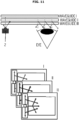
- Fig. 1 schematically illustrates the limitation of the field of view when using diffractive optical elements in augmented reality devices known from the prior art.
- the abscissa is the horizontal field of view (FOV)
- the ordinate is the vertical field of view.
- a square is shown, which is an image that must be transmitted to the user for viewing. If the transmitted image interacts with a diffractive optical element, which takes the transmitted image to the right (arrow of the vector Kin) and the image enters inside the ring shown in Fig. 1 .
- the ring represents the region of the angular components of the propagating radiation (the region of the components of the wave vectors of the propagating radiation) that propagate in the waveguide, but do not propagate outside the waveguide.
- a corner component represents a specific point on an angular grid with angular coordinates such as Bx, By, Bz.
- the inner boundary of the ring is the area of the angle of total internal reflection (TIR), that is, the critical angle at which radiation propagates without leaving the waveguide.
- the outer boundary of the ring is the boundary of the radiation existing inside the waveguide, that is, the angle of propagation of radiation is 900 inside the waveguide. Thus, there is radiation inside the waveguide that propagates at angles from the TIR angle to an angle of 900.
- each of the diffractive optical elements gives its own limitation in the field of view, thus, the fewer diffractive optical elements are contained in the augmented reality device, the better.
- Fig. 1 illustrates one set of diffractive optical elements that outputs a specific portion of the field of view.
- the resulting field of view formed by such a set of diffractive optical elements is 300 by 300.
- the standard way to increase the field of view is to increase the number of waveguides that transmit the image.
- the increase in the number of waveguides increases the thickness of the augmented reality display, weight, and also decreases the transparency of such augmented reality display. If, at the same time, the thickness of the waveguides is reduced, this will lead to a deterioration in the image perceived by the eye, since with a decrease in the thickness of the waveguide, more than one image output enters the pupil, due to the unevenness and non-flatness of the waveguide itself, more than one input image enters into the eyes, that is, double vision occurs image, the resolution begins to drop sharply, the image quality deteriorates.
- the refractive index of waveguides and materials of diffractive optical elements is increased.
- the range of angles that exist in the waveguide but which do not exist in air increases.
- the user sees an image with a large field of view.
- materials with a high refractive index have absorption in the blue region of the spectrum, which means that when the user views the image, the blue part of the spectrum of the real image is lost, in addition, it is impossible to transmit the blue part of the spectrum of the virtual superimposed image, then there is a loss of color in the image.
- the field of view is increased by changing the architecture of the planar waveguides.
- the most famous change is that instead of using one set of diffractive optical elements, two sets of diffractive optical elements are used, each of the sets giving a different part of the field of view.
- two sets it is possible to double the width of the field of view, but only the vertical field of view is increased, while it is preferable to increase both the vertical field of view and the horizontal field of view. That is, with this approach, there is a loss of the horizontal form factor.
- form factor refers to the aspect ratio of the displayed image.
- the horizontal form factor is an image with a larger horizontal margin than a vertical one.
- the vertical form factor is an image with a larger vertical margin than a horizontal one.
- the horizontal or vertical form factor indicates the aspect ratio of the displayed image.
- the vertical form factor and the input diffraction grating are located in relation to the output diffraction grating, for example, on the left, then if the waveguide is turned by 90 ⁇ , then the input diffraction grating will be on top, and the form factor will change from the vertical form factor to horizontal form factor. If the in-coupling diffractive element is on top, then the light must also be introduced into it from above, that is, the image projector must also be attached from above. Thus, the glasses become bulky and more like a helmet.
- the image projector is located on the side while maintaining the horizontal form factor.
- augmented reality devices Another problem with augmented reality devices is their color dispersion. That is, if there is one waveguide with a certain number of sets of diffraction gratings that transmit an image, then such a waveguide will not transmit a full-color image over the entire image field, one part of the image will be visible to the user in red, another part of the image will be visible to the user in green and the third part of the image will be visible to the user in blue. The user will only have access to a small area where he can see the full color image. To solve such a problem, the prior art uses several waveguides, each waveguide being responsible for its own color, or for two adjacent colors. Thus, the thickness of the augmented reality device is increased.
- the document provides systems and methods for creating head-up displays (HUDs) using waveguides that include Bragg gratings.
- HUDs head-up displays
- the disadvantage of the known solution is the small width of the field of view, the large overall dimensions of the device.
- the prototype of the invention is the solution disclosed in document US 10185151 B2, publication date 22.01.2019 .
- the known solution provides a waveguide display with a small form factor, a wide area within which the eye can see the entire image completely, without loss, and a wide field of view.
- a known waveguide display is used to present media to a user.
- the waveguide display includes a light source assembly, an output waveguide, and a controller.
- the light source assembly includes one or more projectors projecting an image along at least one dimension.
- the output waveguide consists of a waveguide body with two opposite surfaces.
- the output waveguide includes a first grating receiving image light propagating along the input wave vector, a second grating, and a third grating opposite the second grating and outputting the expanded image light with wave vectors corresponding to the input wave vector.
- the controller controls the scanning of one or more source assemblies to form a 2D image.
- the disadvantage of the known solution is also the insufficient width of the field of view, since in order to increase the width of the field of view in the known solution only two sets of optical elements are used; the large overall dimensions of the device are also a disadvantage.
- the proposed invention solves all the above problems, allows you to achieve a wide field of view with a small thickness and full color, with good resolution and with the introduction of radiation from the side.
- an architecture (structure) of diffraction optical elements in a waveguide for an augmented reality device comprising: an in-coupling diffractive element configured to input radiation from the projector, and including a first linear diffractive optical element of the in-coupling diffractive element and a second linear diffractive optical element of in-coupling diffractive element; a first multiplying diffractive element and a second multiplying diffractive element configured to multiply radiation; an out-coupling diffractive element configured to multiply radiation and output radiation from the waveguide, and includes a first linear diffractive optical element of the out-coupling diffractive element, a second linear diffractive optical element of the out-coupling diffractive element, a third linear diffractive optical element of the out-coupling diffractive element; moreover, the in-coupling diffractive element is configured during the operation of the augmented reality device, to separate the image from the projector into the color components of the image red, green, blue, and the direction of the path of the beambeams of each
- the sum of the vectors of all diffractive elements in each set is equal to zero.
- the first set of diffractive elements and the third set of diffractive elements are configured to conduct the upper part of the field of view
- the second set of diffractive elements and the fourth set of diffractive elements are configured to conduct the lower part of the field of view.
- All the diffractive elements are applied to one side of the waveguide.
- the first and second sets of diffractive elements are located on one side of the waveguide, and the third and fourth sets of diffractive elements are located on the opposite side of the waveguide.
- Proposed is a method for operation of the architecture of diffractive optical elements, wherein the method comprises the stages at which: the radiation from the projector enters the input diffractive element, in which it is divided into the red component of the image, the blue component of the image and the green component of the image and is directed to the sets of diffractive elements operating simultaneously, while the first set of diffractive elements operates as follows: the green component of the image enters on the first linear diffractive optical element of the in-coupling diffractive element, then enters the output diffractive element, where radiation is multiplied by the first linear diffractive optical element of the out-coupling diffractive element, and is output to the user's eye using the second linear diffractive optical element of the output diffractive element, the blue component enters on the first linear diffractive optical element of the in-coupling diffractive element, on which that part of it diffracts, which propagates at an angle different from the angle of incidence of the green component, enters the out-coupling diffractive element, where multiplication
- the method comprises the stages at which: the radiation from the projector enters the input diffractive element, in which it is divided into the red component of the image, the blue component of the image and the green component of the image and is directed to the sets of diffractive elements operating simultaneously, while the first set of diffractive elements operates as follows: green upper component enters on the first linear diffractive optical element of the in-coupling diffractive element, then enters the out-coupling diffractive element, where radiation is multiplied by the first linear diffractive optical element of the out-coupling diffractive element, and is output to the user's eye using the second linear diffractive optical element of the out-coupling diffractive element, the blue upper component enters on the first linear diffractive optical element of the in-coupling diffractive element, on which that part of it diffracts, which propagates at horizontal angle different from the angles of incidence of the green component, enters into the output diffractive element, where multi
- Also proposed is a device for displaying an augmented reality comprising: an image projector; a waveguide containing the proposed architecture of diffractive optical elements.
- Proposed is a device for displaying augmented reality, comprising: an image projector; the first waveguide containing the proposed architecture of diffractive optical elements, operating to expand the horizontal field of view and eliminate the dispersion of the image, the second waveguide containing the proposed architecture of diffractive optical elements, operating to expand the vertical field of view.
- Proposed is a device for displaying augmented reality, comprising: an image projector; a waveguide containing the proposed architecture of diffractive optical elements, the first and second sets of diffractive elements are located on one side of the waveguide, the third and fourth sets of diffractive elements are located on the opposite side of the waveguide.
- Also proposed is a device for displaying an augmented reality comprising: an image projector; at least one waveguide containing at least one proposed architecture of diffractive optical elements.
- augmented reality glasses containing an element for the left eye and an element for the right eye, and each of the elements for the left and right eyes is a device for displaying an augmented reality, wherein a waveguide including a diffractive optical element architecture is located in each of the right-eye element and the left-eye element such that the out-coupling diffractive element is located opposite the user's eye.
- augmented reality glasses containing an element for the left eye and an element for the right eye, and each of the elements for the left and right eyes is a device for displaying an augmented reality, wherein the first and second waveguides are disposed in each of the right-eye element and the left-eye element such that the out-coupled diffractive elements are located opposite the user's eye.
- a narrow pitch interval and a wide viewing angle by mounting a substrate, in which a thin film transistor circuit is provided and an inorganic light emitting diode is mounted on an upper surface of the substrate, to a module substrate, and it is possible to facilitate circuit inspection and replacement and manufacturing process.
- the present invention includes a waveguide including a diffractive architecture that is a structure of diffractive optical elements.
- the diffractive architecture (structure) includes four different sets of diffractive optical elements. Diffractive optical elements are diffractive gratings and will be referred to hereinafter as "diffractive elements" for convenience.
- the set of diffractive optical elements contains three diffractive elements, namely, an in-coupling diffractive element, multiplying the diffractive element, and an out-coupling diffractive element. Each set of diffractive elements is designed in such a way that it displays its own part of the augmented reality image.
- the output optical element produces an output of the image from different diffractive elements.
- the proposed invention is aimed at reducing the overall dimensions of the augmented reality device, the proposed invention solves the problem of color dispersion, since each pair of sets of diffractive elements can conduct differently colored parts of the image that will not overlap each other. That is, thanks to the proposed invention, when using only one waveguide, a wide and full-color field of view is provided.
- the picture transmitted from the projector must interact alternately with at least three linear diffraction gratings, namely with the in-coupling diffraction grating, multiplying diffraction grating and out-coupling diffraction grating.
- HOE holographic
- DOE diffractive
- the vector of the diffraction grating is the wave vector of the diffraction grating directed perpendicularly to the grating lines and located in the same plane with its operating surface. If we consider the grating data as vectors of these lattices, then, in order to obtain an undistorted image, the vectors of these three diffraction lattices must form a closed two-dimensional figure, that is, the sum of all vectors must be zero.
- the input wide field of view at the output turns into a narrow picture, which is not quite comfortable to view, since if the pupil of the eye looks forward, only the central field of the image is clearly visible, while the parts of the image located at , represent a dark area, and if the pupil of the eye is displaced in the vertical direction, then on the contrary, the central part will appear as a dark area. That is, in the known classical systems, the user can see only a narrow strip of the image. Since it is initially assumed that the dimensions of the transmitted image coincide with the field of view of the waveguide, the field of view coincides with the field of the image.
- the waveguide architecture proposed in the present invention allows an increase in the width of the field of view.
- Fig. 2 illustrates the architecture of the proposed waveguide with division into diffractive elements X, Y, Z.
- X is an in-coupling diffractive element.
- the in-coupling diffractive element X includes two linear optical elements.
- the two Y diffractive elements are multiplying diffractive elements.
- Out-coupling diffractive element Z - is a diffractive element where both radiation multiplication and radiation output are provided.
- Out-coupling diffractive element Z includes three linear diffractive optical elements.
- Beams I and II are introduced by the in-coupling diffractive element X. Beam I interacts with the out-coupling diffractive element Z and is multiplied in it into beams IV. Beams II enter on the multiplying diffractive elements Y, where they are multiplied into beams III, which exit from the multiplying diffraction gratings Y and enter the output diffractive element Z. Beams III and IV are output from the out-coupling diffractive element Z.
- In-coupling diffractive element X includes two linear optical elements. Moreover, the in-coupling diffractive element X is designed in such a way that one of the linear diffractive optical elements introduces radiation towards the output diffractive element Z, using one diffraction order, and the other of the linear diffractive elements introduces radiation towards the multiplying diffractive elements Y, using as "+1 "Diffraction order" and "-1" diffraction order.
- the radiation that is introduced towards the out-coupling diffractive element Z differs from the radiation that is introduced towards the multiplying diffractive element Y, that is, these are different parts of the field of view. This means that one part of the field of view is introduced towards the multiplying diffractive elements Y, and another part of the field of view is introduced towards the out-coupling diffractive element Z. These parts propagate inside the waveguide at different angles.
- the out-coupling diffractive element Z outputs radiation from four different diffractive elements: from two linear optical elements of the output diffractive element Z and from two multiplying diffractive elements Y. As shown in Fig. 3 out-coupling diffractive element Z contains three linear diffractive optical elements (1, 2, 3).
- the radiation transmitted from the first and second multiplying diffractive elements Y enters the out-coupling diffractive element Z and is outputted by the third linear diffractive optical element 3 of the out-coupling diffractive element Z. Moreover, the vector of the third diffractive optical element 3 is directed towards the in-coupling diffractive element X.
- the out-coupling diffractive element Z (zone Z) is multiplying and outputting radiation from multiplying and outputting linear diffractive optical elements:
- the principle of operation of diffractive optical elements operating for multiplication is known to be as follows.
- the beam propagating inside the waveguide enters on the multiplying diffractive element and part of the radiation of this beam is diffracted by the multiplying diffractive element, forming diffraction orders, in this case the "+1" diffraction order is considered.
- a beam that passed without diffraction continues to propagate along its original path, and after re-reflection from the planes of the waveguide again enters on the multiplying diffraction element, and part of the radiation of this beam is again diffracted by the multiplying grating, forming a "+1" diffraction order.
- the first diffracted and the second diffracted beams are parallel to each other, but propagate at a fixed distance from each other. Thus, from one beam, many parallel beams are obtained, that is, reproduction occurs.
- the set 1 of diffractive elements consists from the first linear diffractive optical element of the in-coupling diffractive element X, and also the first and second linear diffractive elements of the out-coupling diffractive element Z.
- the set 2 of diffractive elements consists from the first linear diffractive optical element of the in-coupling diffractive element X, and also the second and first linear diffractive optical elements of the out-coupling diffractive element Z.
- the set 3 of the diffractive elements consists of a second linear diffractive optical element of the in-coupling diffractive element X of the first multiplying diffractive optical element Y and the third linear diffractive optical element of the out-coupling diffractive element Z.
- the set 4 of the diffractive elements consists of a second linear diffractive optical element of the in-coupling diffractive element X of the second multiplying diffractive optical element Y and the third linear diffractive optical element of the out-coupling diffractive element Z.
- light separation of the entire field of view by sets of diffractive elements is implemented as follows. Odd sets 1 and 3 of the diffractive elements are responsible for the upper part of the field of view. Even sets 2 and 4 of the diffractive elements are responsible for the upper part of the field of view. Sets 1 and 2 of diffractive elements spend the entire blue part of the field of view and half of the green part of the field of view. Sets 3 and 4 of diffractive elements spend the entire red part of the field of view and half of the green part of the field of view.
- the terms "straight space” and "angular space” define the coordinate grid in which the analysis / calculation is performed.
- the coordinate grid is defined by spatial coordinates (x, y, z directions).
- the grid is defined by angular coordinates (for example Ax, Ay, Az).
- the proposed invention takes into account not only the direction of propagation of radiation (angular space), but also those places inside the waveguide where this radiation propagates (straight space).
- the same point on the grid of angular coordinates can occupy more than one part of the transmitted image, since different parts of the transmitted image occupy the same point on the grid of angular coordinates in different places inside the waveguide, that is, they are separated in direct space.
- Fig. 5a illustrates a vector diagram of a proposed diffractive element architecture.
- the K 1 K 2 K 6 vectors correspond to linear diffractive optical elements of the input diffractive element X.
- the K 5 K 7 K 8 vectors correspond to the out-coupling diffractive element Z.
- Vectors K 1 , K 2 correspond to "+1" and "-1" diffraction orders of the second linear diffractive optical element of the in-coupling diffractive element X.
- the vector K 6 corresponds to the first linear diffractive optical element of the in-coupling diffractive element X.
- the K 3 vector corresponds to the second multiplying diffractive element Y.
- the K 4 vector corresponds to the first multiplying diffractive element Y.
- the K 8 vector corresponds to the first linear diffractive optical element of the out-coupling diffractive element Z.
- the vector K 7 corresponds to the second linear diffractive optical element of the out-coupling diffractive element Z.
- the vector K 5 corresponds to the third linear diffractive optical element of the out-coupling diffractive element Z.
- the above-mentioned sets of diffractive elements operate simultaneously. Radiation from the projector enters on the in-coupling diffractive optical element X in which it is divided at different angles into red, green and blue components.
- the set 1 of diffractive elements operates as follows.
- the green component of the image enters on the first linear diffractive optical element of the in-coupling diffractive element X, then enters the out-coupling diffractive element Z, where radiation is multiplied by the first linear diffractive optical element of the out-coupling diffractive element Z, and is output to the user's eye using the second linear diffractive optical element of the out-coupling diffractive element Z.
- the blue component enters on the first linear diffractive optical element of the in-coupling diffractive element X, on which diffracted is part of it that propagates in air at an angle different from the angle of incidence of the green component. It enters on the out-coupling diffractive element Z, where multiplication occurs on the first linear diffractive optical element of the out-coupling diffractive element Z, and is output into the user's eye using the second linear diffractive optical element of the out-coupling diffractive element Z.
- the set 2 of diffractive elements operates as follows.
- the green component enters on the first linear diffractive optical element of the in-coupling diffractive element X, then enters the out-coupling diffractive element Z, where radiation is multiplied by the second linear diffractive optical element of the out-coupling diffractive element Z, and is output to the user's eye using the first linear diffractive optical element of the out-coupling diffractive element Z.
- the blue component enters on the first linear diffractive optical element of the in-coupling diffractive element X, on which diffracted is part of it that propagates in air at an angle different from the angle of incidence of the green component. It enters on the out-coupling diffractive element Z, where multiplication occurs on the second linear diffractive optical element of the out-coupling diffractive element Z, and is output to the user's eye using the first linear diffractive optical element of the out-coupling diffractive element Z.
- the set 3 of diffractive elements operates as follows.
- the green component enters the second linear diffractive optical element of the in-coupling diffractive element X, then enters the first multiplying diffractive element Y, where multiplication occurs, after which it enters the third linear diffractive optical element of the out-coupling diffractive element Z and is output to the user's eye.
- the red component enters on the second linear diffractive optical element of the input diffractive element X, on which diffracted is that part of it, that propagates in air at an angle different from the angle of incidence of the green component. Then it enters on first multiplying diffractive element Y, where multiplication takes place, after which it enters the third linear diffractive optical element of the out-coupled diffractive element Z and is output to the user's eye.
- the set 4 of diffractive elements operates as follows.
- the green component enters on the second linear diffractive optical element of the in-coupling diffractive element X, then enters on the second multiplying diffractive element Y, where multiplication occurs, after which it enters the third linear diffractive optical element of the out-coupling diffractive element Z and is output to the user's eye.
- the red component enters on the second linear diffractive optical element of the input diffractive element X, on which diffracted is that part of it, that propagates in air at an angle different from the angle of incidence of the green component. Then it enters on the second multiplying diffractive element Y, where multiplication takes place, after which it enters on the third linear diffractive optical element of the out-coupling diffractive element Z and is output to the user's eye.
- the input diffractive element X consists of at least two linear diffraction gratings (the first and second linear diffractive optical elements of the in-coupling diffractive element X).
- the first linear diffractive optical element of the in-coupling diffractive element X introduces radiation towards the out-coupling diffractive element Z, while two parts of the green image are introduced at once, which are then separated during multiplication on the corresponding linear diffractive elements of the out-coupling diffractive element Z.
- the second linear diffractive optical element of the in-coupling diffractive element X introduces two other parts of the green image towards the first and second multiplying diffractive elements Y, respectively. This separation is achieved by choosing the parameters of the diffraction gratings, namely, the choice of the spatial frequency (period) and orientation.
- the first linear diffractive optical element of the in-coupling diffractive element X has a higher spatial frequency (i.e., a shorter period) than the second linear diffractive optical element of the in-coupling diffractive element X.
- the blue component diffracts into the waveguide mode on the first linear the diffractive optical element of the in-coupling diffractive element X, and the red one is on the second one.
- the green component is between red and blue in the spectrum, therefore, it is divided between the first and second linear diffractive elements of the in-coupling diffractive element X as shown in FIG. 4 .
- Fig. 6 shows a coordinate grid of angular for each of the zones of the corner space (zone Z on the right, zone Y at the top, zone Y at the bottom). In zone Z, the upper diagonal quarter of the angular space is occupied by a part of field 2, that is, the image field, for which a set 2 diffractive elements is responsible.
- zone Z the upper diagonal quarter of the angular space is occupied by a part of field 1, that is, the image field, for which a set 1 diffractive elements is responsible.
- zones Y the lower and upper diagonal quarters remain free from parts of the image field, for which 1 and 2 sets of diffractive elements are responsible, respectively, therefore, in the upper zone Y, the upper diagonal quarter is occupied by part of field 4, that is, the image field, for which a set 4 diffractive elements is responsible.
- the lower diagonal quarter is occupied by part of field 3, that is, the image field, for which a set of 3 diffractive elements is responsible.
- part of field 3 that is, the image field, for which a set of 3 diffractive elements is responsible.
- the parts of the image for which sets 1 and 3 of the diffractive elements are responsible do not mix with each other, parts 2 and 4 also do not mix with each other. This happens because the same parts of the angular space are occupied in the waveguide at different points of the direct (local, coordinate) space.
- the radiation that is transmitted through sets 1 and 2 does not propagate inside the waveguide in the places where the multiplying diffractive elements Y are located, that is, the angular components occupied by sets 1 and 2, for example, in the zone where the out-coupling diffractive element Z can be used by sets 3 and 4 in the zones where the multiplying diffractive elements Y are located.
- the Y zone and the Z zone use the same angular components to operate different sets of gratings.
- the sets of diffraction gratings are separated in direct space, which makes it possible to use in one waveguide not two, but four sets of diffraction gratings, where each set of diffraction gratings transmits a separate part of the field of view, that is, it is possible to conduct a field of view twice as large as in the known prior art, since known from the prior art are only solutions having two or less sets of diffractive elements on one waveguide. Since each set of diffractive elements conveys a fixed angular size of the field of view, doubling the number of sets of diffractive elements on the waveguide doubles the field of view.
- the radiation that is introduced by the second linear diffractive optical element of the input diffractive element X towards the first and second multiplying diffractive elements Y, respectively, can propagate at any angles, since the radiation that is introduced by the first linear diffractive optical element of the input diffractive element X toward the output diffractive element Z does not apply in places where multiplying diffractive elements Y.
- Each of the sets is responsible for conducting different parts of the field of view, not only in angle, but also in color.
- Each pair of sets of diffractive elements provides different colored horizontal portions of the field of view, increasing the resulting horizontal viewing angle.
- Each point of the field of view is determined by three variables: angular coordinates horizontally (Ax) and vertical (Ay), as well as color (R, G, B).
- three points of the field of view correspond to a certain point on the grid of angular coordinates with coordinates Ax and Ay.
- the division of the field of view into sets occurs not only by angular coordinates, but also by color.
- the waveguide is designed in such a way that the radiation that interacts with sets 1 and 2 does not interact with sets 3 and 4, for the green part of the field of view, one half of the field of view interacts with sets 1 and 2, with sets 3 and 4 - the second half of the field of view. Therefore, it is possible to display for viewing to the user different spectral-angular parts of the field of view, and the chromatic dispersion is compensated.
- the waveguide is designed by means of the parameters of the diffractive elements, namely, through the spatial orientation of the diffractive elements and the spatial period of the diffractive elements, which are described by the vector of the diffractive optical element.
- Vectors K 1 _ K 8 are vectors of linear diffractive elements as described above.
- Vector k l,x,y is the wave vector of an electromagnetic wave, defined by three coordinates l, x, y, where l is the length of the electromagnetic wave, x is the angular coordinate of the electromagnetic wave in the x direction, y is the angular coordinate of the electromagnetic wave in the y direction.
- the required parameters of the diffractive elements can be calculated analytically.
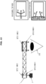
- Fig. 8 schematically illustrates an augmented reality display system.
- the proposed system consists of at least one waveguide 1, which includes diffractive optical elements, a projector 2 that generates an image.
- Diffractive optical elements in the waveguide are an input diffractive optical element X, the first and second multiplying diffractive elements Y (not visible in the view shown in Fig. 8 ), and an out-coupling diffractive element Z, which both multiplies and outputs the image components into the user's eye .
- the image generated by the projector 2 enters the architecture of the diffractive elements through the input diffractive element X, propagates through the architecture of the diffractive elements in the waveguide and exits the out-coupling diffractive element Z, entering the user's eye.
- the sets of diffractive elements are used not to compensate for the color dispersion of the image while simultaneously increasing the horizontal field of view, as described above, but to increase the vertical field of view. Compensating for the color dispersion of an image without increasing the vertical field of view allows to increase only the horizontal field of view.
- grating sets are designed differently, sets 1 and 2 will transmit the outermost parts of the vertical image, sets 3 and 4 will transmit more central parts.
- the design is carried out in accordance with the system of equations presented below.
- Vectors K 1 _ K 8 are vectors of linear diffractive elements as described above.
- Vector k l,x,y is the wave vector of an electromagnetic wave, defined by three coordinates l, x, y, where l is the length of the electromagnetic wave, x is the angular coordinate of the electromagnetic wave in the x direction, y is the angular coordinate of the electromagnetic wave in the y direction.
- the initial data for solving this system of equations are the used lengths of electromagnetic waves ( ⁇ b ⁇ r ), the refractive indices of the optical system for the used wavelengths ( n ⁇ b ,n ⁇ r ), the aspect ratio of the sides of the field of view ( ⁇ / ⁇ ), as well as the geometric relationships of the vectors of linear elements arising from the geometric features of the waveguide architecture as seen from figure 4a.
- the conditions for expanding the vertical field of view are the same as for expanding the horizontal field of view and dispersion compensation. These conditions follower from the geometric arrangement of the diffractive elements, and symmetry considerations.
- the system of equations (1) gives the grating parameters to eliminate dispersion and increase the horizontal field of view
- the system of equations (2) gives the grating parameters to increase the vertical field of view.
- the invention has two implementations. In the first, there is a division by colors and horizontal parts of the field of view. Secondly, by colors and vertical parts of the field of view. Both of these executions are equivalent and are used depending on the setting problem.
- the image is generated by the projector and in this case the image is a function of the brightness for three colors in an angular coordinate grid.
- An image can be thought of as a set of wave vectors with corresponding angular coordinates and wavelengths.
- the periods and orientation of the diffractive elements are calculated in such a way that some sets operate with the central part, while other sets operate with the extreme parts. All this can be calculated using the presented system of equations (2).
- the width of the eye motion box increases, that is, the area within which the eye, moving, can see the entire virtual image completely, without losses.
- the field of view (the field of view of the optical system (angular field) is the cone of beams emerging from the optical system, forming the images) is increased by increasing the number of sets of diffractive elements. How exactly the field of view increases (horizontally or vertically) depends on the choice of the diffraction elements, according to the systems of equations (1) or (2).
- Fig. 7 illustrates the light separation of the entire field of view across sets of diffractive optical elements in the case of vertical expansion of the field of view.
- the waveguide with the architecture of the diffraction gratings operates as follows:
- Sets 1 and 2 of diffractive elements expand the edges of the vertical field of view, sets 3 and 4 expand the center of the field of view.
- Radiation from the projector enters on the in-coupling diffractive optical element X in which it is divided at different angles into red, green and blue components.
- the set 1 of diffractive elements operates as follows.
- the green upper component enters on the first linear diffractive optical element of the in-coupling diffractive element X, then enters the out-coupling diffractive element Z, where radiation is multiplied by the first linear diffractive optical element of the out-coupling diffractive element Z, and is output to the user's eye using the second linear diffractive optical element of the out-coupling diffractive element Z.
- the blue upper component enters on the first linear diffractive optical element of the in-coupling diffractive element X, on which diffracted is part of it that propagates in air at a horizontal angle different from the angle of incidence of the green component. It enters on the out-coupling diffractive element Z, where multiplication occurs on the first linear diffractive optical element of the out-coupling diffractive element Z, and is output into the user's eye using the second linear diffractive optical element Z.
- the red upper component enters on the first linear diffractive optical element of the input diffractive element X, on which that part of it diffracts, which propagates in air at a horizontal angle different from the angles of incidence of the green component and the blue component, than it enters the out-coupling diffractive element Z, where multiplication occurs on the first linear diffractive element of the out-coupling diffractive element, and is output to the user's eye by the second linear diffractive optical element of the out-coupling diffractive element Z.
- the set 2 of diffractive elements operates as follows.
- the green lower component enters on the first linear diffractive optical element of the in-coupling diffractive element X, then enters on the out-coupling diffractive element Z, where radiation is multiplied by the second linear diffractive optical element of the out-coupling diffractive element Z, and is output to the user's eye using the first linear diffractive optical element of the out-coupling diffractive element Z.
- the blue lower component enters on the first linear diffractive optical element of the in-coupling diffractive element X, on which that part of it diffracts, which propagates in air at a horizontal angle different from the angle of incidence of the green component, enters the out-coupling diffractive element Z, where multiplication occurs on the second linear the diffractive optical element of the out-coupling diffractive element Z, and is output to the user's eye using the first linear diffractive optical element of the out-coupling put diffractive element Z.
- the horizontal angle hereinafter refers to the angular component of the incident light directed towards the vector of the input diffraction K 6 grating.
- the red lower component enters on the first linear diffractive optical element of the in-coupling diffractive element X, on which that part of it diffracts, which propagates in air at a horizontal angle different from the angles of incidence of the green component and the blue component. It enters on the in-coupling diffractive element X, where multiplication occurs on the second linear diffractive optical element of the out-coupling diffractive element Z, and it is output to the user's eye using the first linear diffractive optical element of the out-coupling diffractive element Z.
- the set 3 of the diffractive elements consisting of a second linear diffractive optical element of the in-coupling diffractive element X of the first multiplying diffractive optical element Y and the third linear diffractive optical element of the out-coupling diffractive element Z, operates as follows.
- the green central upper component enters the second linear diffractive optical element of the in-coupling diffractive element X, then enters the first multiplying diffractive element Y, where multiplication occurs, and then enters the third linear diffractive optical element of the out-coupling diffractive element Z and is output to the user's eye.
- the red central upper component enters on the second linear diffractive optical element of the in-coupling diffractive element X, on which diffracted is part of it that propagates in air at a horizontal angle different from the angle of incidence of the green component. Then it enters on first multiplying diffractive element Y, where multiplication takes place, after which it enters the third linear diffractive optical element of the out-coupled diffractive element Z and is output to the user's eye.
- the blue central upper component enters on the second linear diffractive optical element of the in-coupling diffractive element X, on which diffracted is part of it that propagates in air at a horizontal angle different from the angles of incidence of the green component and the red component. Then it enters on first multiplying diffractive element Y, where multiplication takes place, after which it enters the third linear diffractive optical element of the out-coupled diffractive element Z and is output to the user's eye.
- the set 4 of diffractive elements operates as follows.
- the green central lower component enters on the second linear diffractive optical element of the in-coupling diffractive element X, then enters on the second multiplying diffractive element Y, where multiplication occurs, and then enters the third linear diffractive optical element of the out-coupling diffractive element Z and is output to the user's eye.
- the red central lower component enters on the second linear diffractive optical element of the in-coupling diffractive element X, on which diffracted is part of it that propagates in air at a horizontal angle different from the angle of incidence of the green component. Then it enters on the second multiplying diffractive element Y, where multiplication takes place, after which it enters on the third linear diffractive optical element of the out-coupling diffractive element Z and is output to the user's eye.
- the blue central lower component enters on the second linear diffractive optical element of the in-coupling diffractive element X, on which diffracted is part of it that propagates in air at a horizontal angle different from the angles of incidence of the green component and red component. Then it enters on the second multiplying diffractive element Y, where multiplication takes place, after which it enters on the third linear diffractive optical element of the out-coupling diffractive element Z and is output to the user's eye.
- FIG. 9 illustrates two schemes of the proposed architecture of diffractive elements.
- the architecture of the diffractive elements can either compensate for the dispersion and expand the horizontal field of view (calculation using the system of equations (1)), or expand the vertical field of vision (calculation using system of equations (2)).
- scheme (a) in which operated are sets of 3 and 4 of diffractive elements, operates with the red and green components of the radiation and expands the right side of the horizontal field of view, as described above
- scheme (b) in which operated are sets 1 and 2 of diffractive elements, operates with blue and green radiation components and expands the left part of the horizontal field of view, as described above ( Figs. 4 , Sa, 5b).
- the architectures of the diffractive elements of each of the waveguides of such a system repeat each other, with one architecture of the diffractive elements on one waveguide configured to compensate for dispersion and increasing the horizontal field of view, and the second architecture of the diffractive elements on the other waveguide is configured to increase the vertical field of view.
- Each of the two waveguides is designed to display its own spectral-angular portion of the field of view.
- the use of two waveguides can significantly increase the field of view.
- the diffractive architecture in the first waveguide the diffractive architecture is located in such a way that an increase in the vertical field of view occurs, and in the second waveguide the diffractive architecture is located in such a way that the image dispersion is compensated and the horizontal field of view increases.
- sets 1 and 2 of diffractive elements operate to expand the field of view along the edges of the image vertically
- sets 3 and 4 operate to expand the field of view in the center of the field of view vertically.
- sets 1 and 2 operate with the left side of the image
- sets 3 and 4 operate with the right side of the image, expanding the field of view horizontally and compensating for dispersion.
- the first waveguide includes the architecture of the diffractive elements calculated by the system of equations (2).
- Radiation from the projector enters on the input diffractive optical element X of waveguide I, in which it is divided at different angles into red, green and blue components.
- the central left part of the red field of view, the central right part of the green field of view and the right part of the blue field of view are passed through the waveguide I. It should be clarified that different parts of the field of view with a breakdown by color are passed due to the chromatic dispersion of the input diffractive element X.
- the order (blue is always to the right, red is always to the left, green is somewhere in between) is valid for any diffractive element.
- “to the right” and “to the left” are not absolute sides, but relative ones, taking into account the fixed input diffractive element to the left of the eye (as shown in all figures). If the input diffractive element is not to the left, but to the right of the eye, then the order changes (blue becomes to the left, red to the right, green somewhere between them). Why exactly these parts are carried out in this performance - based on the calculation, it is such a breakdown into parts of the field that is capable of providing the maximum field of view.
- Set 1 of diffractive elements of waveguide I operates as follows.
- the green upper component enters on the first linear diffractive optical element of the in-coupling diffractive element X, then enters the out-coupling diffractive element Z, where multiplication occurs on the first linear diffractive optical element of the out-coupling diffractive element Z, and is output into the user's eye using the second linear diffractive optical element of the diffractive element Z.
- the blue upper component enters on the first linear diffractive optical element of the in-coupling diffractive element X, on which diffracted is part of it that propagates in air at a horizontal angle different from the angle of incidence of the green component. It enters on the out-coupling diffractive element Z, where multiplication occurs on the first linear diffractive optical element of the out-coupling diffractive element Z, and is output into the user's eye using the second linear diffractive optical element of the out-coupling diffractive element Z.
- the red upper component enters on the first linear diffractive optical element of the in-coupling diffractive element X, on which diffracted is part of it that propagates in air at a horizontal angle different from the angles of incidence of the green component and blue component. It enters on the out-coupling diffractive element Z, where multiplication occurs on the first linear diffractive optical element of the out-coupling diffractive element Z, and is output into the user's eye using the second linear diffractive optical element of the out-coupling diffractive element Z.
- Set 2 of diffractive elements of waveguide I operates as follows.
- the green lower component enters on the first linear diffractive optical element of the in-coupling diffractive element X, then enters on the out-coupling diffractive element Z, where radiation is multiplied by the second linear diffractive optical element of the out-coupling diffractive element Z, and is output to the user's eye using the first linear diffractive optical element of the out-coupling diffractive element Z.
- the blue lower component enters on the first linear diffractive optical element of the in-coupling diffractive element X, on which diffracted is part of it that propagates in air at a horizontal angle different from the angle of incidence of the green component. It enters the output diffractive element Z, where multiplication occurs on the second linear diffractive optical element of the diffractive element Z, and is output to the user's eye using the first linear diffractive optical element of the out-coupling diffractive element Z.
- the red lower component enters on the first linear diffractive optical element of the in-coupling diffractive element X, on which that part of it diffracts, which propagates in air at a horizontal angle different from the angles of incidence of the green component and the blue component. It enters on the in-coupling diffractive element X, where multiplication occurs on the second linear diffractive optical element of the out-coupling diffractive element Z, and it is output to the user's eye using the first linear diffractive optical element of the out-coupling diffractive element Z.
- Set 3 of diffractive elements of waveguide I operates as follows.
- the green central upper component enters the second linear diffractive optical element of the in-coupling diffractive element X, then enters the first multiplying diffractive element Y, where multiplication occurs, and then enters the third linear diffractive optical element of the out-coupling diffractive element Z and is output to the user's eye.
- the red central upper component enters on the second linear diffractive optical element of the in-coupling diffractive element X, on which diffracted is part of it that propagates in air at a horizontal angle different from the angle of incidence of the green component. Then it enters the first diffractive optical element Y, where multiplication takes place, after which it enters the third linear diffractive optical element of the output diffractive element Z and is output to the user's eye.
- the blue central upper component enters on the second linear diffractive optical element of the in-coupling diffractive element X, on which diffracted is part of it that propagates in air at a horizontal angle different from the angles of incidence of the green component and the red component. Then it enters the first diffractive optical element Y, where multiplication takes place, after which it enters the third linear diffractive optical element of the output diffractive element Z and is output to the user's eye.
- Set 4 of diffractive elements of waveguide I operates as follows.
- the green central lower component enters on the second linear diffractive optical element of the in-coupling diffractive element X, then enters the second diffractive optical element Y, where multiplication takes place, and then enters the third linear diffractive optical element of the output diffractive element Z and is output to the user's eye.
- the red central lower component enters on the second linear diffractive optical element of the in-coupling diffractive element X, on which diffracted is part of it that propagates in air at a horizontal angle different from the angle of incidence of the green component. Then it enters on the second multiplying diffractive element Y, where multiplication takes place, after which it enters on the third linear diffractive optical element of the out-coupling diffractive element Z and is output to the user's eye.
- the blue central lower component enters on the second linear diffractive optical element of the in-coupling diffractive element X, on which diffracted is part of it that propagates in air at a horizontal angle different from the angles of incidence of the green component and red component. Then it enters on the second multiplying diffractive element Y, where multiplication takes place, after which it enters on the third linear diffractive optical element of the out-coupling diffractive element Z and is output to the user's eye.
- waveguide II Radiation from the projector enters on the input diffractive optical element X of waveguide II, in which it is divided at different angles into red, green and blue components.
- the extreme right part of the red field of view, the extreme left part of the green field of view and the left part of the blue field of view are passed through the waveguide II.
- waveguide II is designed to compensate not for its own dispersion, but for the dispersion of waveguide I.
- Set 1 of diffractive elements of waveguide II operates as follows.
- the red component enters on the first linear diffractive optical element of the input diffractive element X, then enters the output diffractive element Z, where multiplication occurs on the first linear diffractive optical element of the output diffractive element Z, and is outputted to the user's eye using the second linear diffractive optical element of the output diffractive element Z.
- Set 2 of diffractive elements of waveguide II operates as follows.
- the red component enters on the first linear diffractive optical element of the in-coupling diffractive element X, then enters the output diffractive element Z, where multiplication occurs on the second linear diffractive optical element of the output diffractive element Z, and is outputted to the user's eye using the first linear diffractive optical element of the out-coupling diffractive element Z.
- Set 3 of diffractive elements of waveguide II operates as follows.
- the green component enters the second linear diffractive optical element of the in-coupling diffractive element X, then enters the first multiplying diffractive element Y, where multiplication occurs, after which it enters the third linear diffractive optical element of the out-coupling diffractive element Z and is output to the user's eye.
- the blue component enters on the second linear diffractive optical element of the in-coupling diffractive element X, on which diffracted is that part of it, that propagates in air at an angle different from the angle of incidence of the green component. Then it enters on first multiplying diffractive element Y, where multiplication takes place, after which it enters the third linear diffractive optical element of the out-coupled diffractive element Z and is output to the user's eye.
- Set 4 of diffractive elements of waveguide II operates as follows.
- the green component enters the second linear diffractive optical element of the in-coupling diffractive element X, then enters the second multiplying diffractive element Y, where multiplication occurs, after which it enters the third linear diffractive optical element of the out-coupling diffractive element Z and is output to the user's eye.
- the blue component enters on the second linear diffractive optical element of the in-coupling diffractive element X, on which diffracted is that part of it, that propagates in air at an angle different from the angle of incidence of the green component. Then it enters on the second multiplying diffractive element Y, where multiplication takes place, after which it enters on the third linear diffractive optical element of the out-coupling diffractive element Z and is output to the user's eye.
- the diagonal field of view when using two waveguides with the proposed architecture of diffraction gratings reaches 62 ⁇ .
- Fig. 11 illustrates the use of a three-waveguide system.
- Radiation from the projector enters on the in-coupling diffractive optical element X of waveguide I, in which it is divided at different angles into green and blue components.
- waveguide I Through waveguide I, the extreme left part of the green field of view and the left central part of the blue field of view are passed.
- different parts of the color-graded field of view are passed due to the chromatic dispersion of the input diffractive element.
- Set 1 of diffractive elements of waveguide I operates as follows.
- the green upper component enters on the first linear diffractive optical element of the in-coupling diffractive element X, then enters the out-coupling diffractive element Z, where radiation is multiplied by the first linear diffractive optical element of the out-coupling diffractive element Z, and is output to the user's eye using the second linear diffractive optical element of the out-coupling diffractive element Z.
- the blue upper component enters on the first linear diffractive optical element of the in-coupling diffractive element X, on which diffracted is part of it that propagates in air at a horizontal angle different from the angle of incidence of the green component. It enters on the out-coupling diffractive element Z, where multiplication occurs on the first linear diffractive optical element of the out-coupling diffractive element Z, and is output into the user's eye using the second linear diffractive optical element of the out-coupling diffractive element Z.
- Set 2 of diffractive elements of waveguide I operates as follows.
- the green lower component enters on the first linear diffractive optical element of the in-coupling diffractive element X, then enters on the out-coupling diffractive element Z, where radiation is multiplied by the second linear diffractive optical element of the out-coupling diffractive element Z, and is output to the user's eye using the first linear diffractive optical element of the out-coupling diffractive element Z.
- the blue lower component enters on the first linear diffractive optical element of the in-coupling diffractive element X, on which diffracted is part of it that propagates in air at a horizontal angle different from the angle of incidence of the green component. It enters on the in-coupling diffractive element X, where multiplication occurs on the second linear diffractive optical element of the out-coupling diffractive element Z, and it is output to the user's eye using the first linear diffractive optical element of the out-coupling diffractive element Z.
- Set 3 of diffractive elements of waveguide I operates as follows.
- the green central upper component enters the second linear diffractive optical element of the in-coupling diffractive element X, then enters the first multiplying diffractive element Y, where multiplication occurs, and then enters the third linear diffractive optical element of the out-coupling diffractive element Z and is output to the user's eye.
- the blue lower component enters on the second linear diffractive optical element of the in-coupling diffractive element X, on which diffracted is part of it that propagates in air at a horizontal angle different from the angle of incidence of the green component. Then it enters on first multiplying diffractive element Y, where multiplication takes place, after which it enters the third linear diffractive optical element of the out-coupled diffractive element Z and is output to the user's eye.
- Set 4 of diffractive elements of waveguide I operates as follows.
- the green central lower component enters on the second linear diffractive optical element of the in-coupling diffractive element X, then enters on the second multiplying diffractive element Y, where multiplication occurs, and then enters the third linear diffractive optical element of the out-coupling diffractive element Z and is output to the user's eye.
- the blue central lower component enters on the second linear diffractive optical element of the input diffractive element X, on which diffracted is part of it that propagates in air at a horizontal angle different from the angle of incidence of the green component. Then it enters on the second multiplying diffractive element Y, where multiplication takes place, after which it enters on the third linear diffractive optical element of the out-coupling diffractive element Z and is output to the user's eye.
- the radiation from the projector that is, the radiation that came out of the waveguide I
- the extreme left part of the red field of view, the central part of the green field of view and the right central part of the blue field of view are passed through the waveguide II.
- Set 1 of diffractive elements of waveguide II operates as follows.
- the green upper component enters on the first linear diffractive optical element of the in-coupling diffractive element X, then enters the out-coupling diffractive element Z, where radiation is multiplied by the first linear diffractive optical element of the out-coupling diffractive element Z, and is output to the user's eye using the second linear diffractive optical element of the out-coupling diffractive element Z.
- the blue upper component enters on the first linear diffractive optical element of the in-coupling diffractive element X, on which diffracted is part of it that propagates in air at a horizontal angle different from the angle of incidence of the green component. It enters the out-coupling diffractive element Z, where multiplication occurs on the first linear diffractive optical element of the output diffractive element Z, and is output into the user's eye using the second linear diffractive optical element of the output diffractive element Z.
- the red upper component enters on the first linear diffractive optical element of the in-coupling diffractive element X, on which diffracted is part of it that propagates in air at a horizontal angle different from the angles of incidence of the green component and blue component. It enters on the out-coupling diffractive element Z, where multiplication occurs on the first linear diffractive optical element of the out-coupling diffractive element Z, and is output into the user's eye using the second linear diffractive optical element of the out-coupling diffractive element Z.
- Set 2 of diffractive elements of waveguide II operates as follows.
- the green lower component enters on the first linear diffractive optical element of the in-coupling diffractive element X, then enters on the out-coupling diffractive element Z, where radiation is multiplied by the second linear diffractive optical element of the out-coupling diffractive element Z, and is output to the user's eye using the first linear diffractive optical element of the out-coupling diffractive element Z.
- the blue lower component enters on the first linear diffractive optical element of the in-coupling diffractive element X, on which diffracted is part of it that propagates in air at a horizontal angle different from the angle of incidence of the green component. It enters on the out-coupling diffractive element Z, where multiplication occurs on the second linear diffractive optical element of the out-coupling diffractive element Z, and is output to the user's eye using the first linear diffractive optical element of the out-coupling diffractive element Z.
- the red lower component enters on the first linear diffractive optical element of the in-coupling diffractive element X, on which that part of it diffracts, which propagates in air at a horizontal angle different from the angles of incidence of the green component and the blue component. It enters on the out-coupling diffractive element Z, where multiplication occurs on the second linear diffractive optical element of the out-coupling diffractive element Z, and is output to the user's eye using the first linear diffractive optical element of the out-coupling diffractive element Z.
- Set 3 of diffractive elements of waveguide II operates as follows.
- the green central upper component enters the second linear diffractive optical element of the in-coupling diffractive element X, then enters the first multiplying diffractive element Y, where multiplication occurs, and then enters the third linear diffractive optical element of the out-coupling diffractive element Z and is output to the user's eye.
- the red central upper component enters on the second linear diffractive optical element of the in-coupling diffractive element X, on which diffracted is part of it that propagates in air at a horizontal angle different from the angle of incidence of the green component. Then it enters on first multiplying diffractive element Y, where multiplication takes place, after which it enters the third linear diffractive optical element of the out-coupled diffractive element Z and is output to the user's eye.
- the blue central upper component enters on the second linear diffractive optical element of the in-coupling diffractive element X, on which diffracted is part of it that propagates in air at a horizontal angle different from the angles of incidence of the green component and the red component. Then it enters on first multiplying diffractive element Y, where multiplication takes place, after which it enters the third linear diffractive optical element of the out-coupled diffractive element Z and is output to the user's eye.
- Set 4 of diffractive elements of waveguide II operates as follows.
- the green central lower component enters on the second linear diffractive optical element of the in-coupling diffractive element X, then enters on the second multiplying diffractive element Y, where multiplication occurs, and then enters the third linear diffractive optical element of the out-coupling diffractive element Z and is output to the user's eye.
- the red central lower component enters on the second linear diffractive optical element of the in-coupling diffractive element X, on which diffracted is part of it that propagates in air at a horizontal angle different from the angle of incidence of the green component. Then it enters on the second multiplying diffractive element Y, where multiplication takes place, after which it enters on the third linear diffractive optical element of the out-coupling diffractive element Z and is output to the user's eye.
- the blue central lower component enters on the second linear diffractive optical element of the in-coupling diffractive element X, on which diffracted is part of it that propagates in air at a horizontal angle different from the angles of incidence of the green component and red component. Then it enters on the second multiplying diffractive element Y, where multiplication takes place, after which it enters on the third linear diffractive optical element of the out-coupling diffractive element Z and is output to the user's eye.
- the radiation from the projector enters on the input diffractive optical element X of the waveguide III, in which it is divided at different angles into red, green and blue components.
- the central right part of the red field of view, the right part of the green field of view and the extreme right central part of the blue field of view are passed through the waveguide III.
- Set 1 of diffractive elements of waveguide III operates as follows.
- the green upper component enters on the first linear diffractive optical element of the in-coupling diffractive element X, then enters the out-coupling diffractive element Z, where radiation is multiplied by the first linear diffractive optical element of the out-coupling diffractive element Z, and is output to the user's eye using the second linear diffractive optical element of the out-coupling diffractive element Z.
- the blue upper component enters on the first linear diffractive optical element of the in-coupling diffractive element X, on which diffracted is part of it that propagates in air at a horizontal angle different from the angle of incidence of the green component. It enters on the out-coupling diffractive element Z, where multiplication occurs on the first linear diffractive optical element of the out-coupling diffractive element Z, and is output into the user's eye using the second linear diffractive optical element of the out-coupling diffractive element Z.
- the red upper component enters on the first linear diffractive optical element of the in-coupling diffractive element X, on which diffracted is part of it that propagates in air at a horizontal angle different from the angles of incidence of the green component and blue component. It enters on the out-coupling diffractive element Z, where multiplication occurs on the first linear diffractive optical element of the out-coupling diffractive element Z, and is output into the user's eye using the second linear diffractive optical element of the out-coupling diffractive element Z.
- Set 2 of diffractive elements of waveguide III operates as follows.
- the green lower component enters on the first linear diffractive optical element of the in-coupling diffractive element X, then enters the out-coupling diffractive element Z, where radiation is multiplied by the second linear diffractive optical element of the out-coupling diffractive element Z, and is output to the user's eye using the first linear diffractive optical element of the diffractive element Z.
- the blue lower component enters on the first linear diffractive optical element of the in-coupling diffractive element X, on which diffracted is part of it that propagates in air at a horizontal angle different from the angle of incidence of the green component. It enters on the in-coupling diffractive element X, where multiplication occurs on the second linear diffractive optical element of the out-coupling diffractive element Z, and it is output to the user's eye using the first linear diffractive optical element of the out-coupling diffractive element Z.
- the red lower component enters on the first linear diffractive optical element of the in-coupling diffractive element X, on which that part of it diffracts, which propagates in air at a horizontal angle different from the angles of incidence of the green component and the blue component. It enters on the in-coupling diffractive element X, where multiplication occurs on the second linear diffractive optical element of the out-coupling diffractive element Z, and it is output to the user's eye using the first linear diffractive optical element of the out-coupling diffractive element Z.
- Set 3 of diffractive elements of waveguide III operates as follows.
- the green central upper component enters the second linear diffractive optical element of the input diffractive element X, then enters the first multiplying diffractive element of the diffractive optical element Y, where multiplication occurs, and then enters the third linear diffractive optical element of the output diffractive element Z and is output to the user's eye.
- the red central upper component enters on the second linear diffractive optical element of the in-coupling diffractive element X, on which diffracted is part of it that propagates in air at a horizontal angle different from the angle of incidence of the green component. Then it enters on first multiplying diffractive element Y, where multiplication takes place, after which it enters the third linear diffractive optical element of the out-coupled diffractive element Z and is output to the user's eye.
- the blue central upper component enters on the second linear diffractive optical element of the in-coupling diffractive element X, on which diffracted is part of it that propagates in air at a horizontal angle different from the angles of incidence of the green component and the red component. Then it enters on first multiplying diffractive element Y, where multiplication takes place, after which it enters the third linear diffractive optical element of the out-coupled diffractive element Z and is output to the user's eye.
- Set 4 of diffractive elements of waveguide III operates as follows.
- the green central lower component enters on the second linear diffractive optical element of the in-coupling diffractive element X, then enters on the second multiplying diffractive element Y, where multiplication occurs, and then enters the third linear diffractive optical element of the out-coupling diffractive element Z and is output to the user's eye.
- the red central lower component enters on the second linear diffractive optical element of the in-coupling diffractive element X, on which diffracted is part of it that propagates in air at a horizontal angle different from the angle of incidence of the green component. Then it enters on the second multiplying diffractive element Y, where multiplication takes place, after which it enters on the third linear diffractive optical element of the out-coupling diffractive element Z and is output to the user's eye.
- the blue central lower component enters on the second linear diffractive optical element of the in-coupling diffractive element X, on which diffracted is part of it that propagates in air at a horizontal angle different from the angles of incidence of the green component and red component. Then it enters on the second multiplying diffractive element Y, where multiplication takes place, after which it enters on the third linear diffractive optical element of the out-coupling diffractive element Z and is output to the user's eye.
- the diagonal field of view when using three waveguides with the proposed architecture of diffraction gratings reaches 76 ⁇ .
- Fig. 12 shows that waveguide architectures can be applied to opposite sides of a single waveguide.
- sets 1 and 2 of diffractive elements can be located on one side of the waveguide
- sets 3 and 4 of diffractive optical elements can be located on the other side of the waveguide.
- Such a structure is easy to manufacture and can be used both to increase the vertical field of view and to increase the horizontal field of view.
- the waveguide operates as follows: Radiation from the projector enters on the in-coupling diffractive optical element X in which it is divided at different angles into red, green and blue components.
- the set 1 of the diffractive elements located on the first side of the waveguide operates as follows.
- the green component enters on the first linear diffractive optical element of the in-coupling diffractive element X, then enters the out-coupling diffractive element Z, where radiation is multiplied by the first linear diffractive optical element of the out-coupling diffractive element Z, and is output to the user's eye using the second linear diffractive optical element of the out-coupling diffractive element Z.
- the blue component enters on the first linear diffractive optical element of the in-coupling diffractive element X, on which diffracted is part of it that propagates in air at an angle different from the angle of incidence of the green component. It enters on the out-coupling diffractive element Z, where multiplication occurs on the first linear diffractive optical element of the out-coupling diffractive element Z, and is output into the user's eye using the second linear diffractive optical element of the out-coupling diffractive element Z.
- the set 2 of the diffractive elements located on the first side of the waveguide operates as follows.
- the green component enters on the first linear diffractive optical element of the in-coupling diffractive element X, then enters the out-coupling diffractive element Z, where radiation is multiplied by the second linear diffractive optical element of the out-coupling diffractive element Z, and is output to the user's eye using the first linear diffractive optical element of the out-coupling diffractive element Z.
- the blue component enters on the first linear diffractive optical element of the in-coupling diffractive element X, on which diffracted is part of it that propagates in air at an angle different from the angle of incidence of the green component. It enters on the out-coupling diffractive element Z, where multiplication occurs on the second linear diffractive optical element of the out-coupling diffractive element Z, and is output to the user's eye using the first linear diffractive optical element of the out-coupling diffractive element Z.
- the set 3 of the diffractive elements located on the second side of the waveguide operates as follows.
- the green component enters the second linear diffractive optical element of the in-coupling diffractive element X, then enters the first multiplying diffractive element Y, where multiplication occurs, after which it enters the third linear diffractive optical element of the out-coupling diffractive element Z and is output to the user's eye.
- the red component enters on the second linear diffractive optical element of the input diffractive element X, on which diffracted is that part of it, that propagates in air at an angle different from the angle of incidence of the green component. Then it enters on first multiplying diffractive element Y, where multiplication takes place, after which it enters the third linear diffractive optical element of the out-coupled diffractive element Z and is output to the user's eye.
- the set 4 of the diffractive elements located on the second side of the waveguide operates as follows.
- the green component enters on the second linear diffractive optical element of the in-coupling diffractive element X, then enters on the second multiplying diffractive element Y, where multiplication occurs, after which it enters the third linear diffractive optical element of the out-coupling diffractive element Z and is output to the user's eye.
- the red component enters on the second linear diffractive optical element of the input diffractive element X, on which diffracted is that part of it, that propagates in air at an angle different from the angle of incidence of the green component. Then it enters on the second multiplying diffractive element Y, where multiplication takes place, after which it enters on the third linear diffractive optical element of the out-coupling diffractive element Z and is output to the user's eye.
- the waveguide operates as follows: Radiation from the projector enters on the in-coupling diffractive optical element X in which it is divided at different angles into red, green and blue components.
- the set 1 of the diffractive elements located on the first side of the waveguide operates as follows.
- the green upper component enters on the first linear diffractive optical element of the in-coupling diffractive element X, then enters the out-coupling diffractive element Z, where radiation is multiplied by the first linear diffractive optical element of the out-coupling diffractive element Z, and is output to the user's eye using the second linear diffractive optical element of the out-coupling diffractive element Z.
- the blue upper component enters on the first linear diffractive optical element of the in-coupling diffractive element X, on which diffracted is part of it that propagates in air at a horizontal angle different from the angle of incidence of the green component. It enters on the out-coupling diffractive element Z, where multiplication occurs on the first linear diffractive optical element of the out-coupling diffractive element Z, and is output into the user's eye using the second linear diffractive optical element of the out-coupling diffractive element Z.
- the red upper component enters on the first linear diffractive optical element of the in-coupling diffractive element X, on which diffracted is part of it that propagates in air at a horizontal angle different from the angles of incidence of the green component and blue component. It enters on the out-coupling diffractive element Z, where multiplication occurs on the first linear diffractive optical element of the out-coupling diffractive element Z, and is output into the user's eye using the second linear diffractive optical element of the out-coupling diffractive element Z.
- the set 2 of the diffractive elements located on the first side of the waveguide operates as follows.
- the green lower component enters on the first linear diffractive optical element of the in-coupling diffractive element X, then enters the out-coupling diffractive element Z, where radiation is multiplied by the second linear diffractive optical element of the out-coupling diffractive element Z, and is output to the user's eye using the first linear diffractive optical element of the diffractive element Z.
- the blue lower component enters on the first linear diffractive optical element of the in-coupling diffractive element X, on which diffracted is part of it that propagates in air at a horizontal angle different from the angle of incidence of the green component. It enters on the in-coupling diffractive element X, where multiplication occurs on the second linear diffractive optical element of the in-coupling diffractive element X, and is output into the user's eye using the first linear diffractive optical element of the out-coupling diffractive element Z.
- the red lower component enters on the first linear diffractive optical element of the in-coupling diffractive element X, on which that part of it diffracts, which propagates in air at a horizontal angle different from the angles of incidence of the green component and the blue component. It enters on the in-coupling diffractive element X, where multiplication occurs on the second linear diffractive optical element of the out-coupling diffractive element Z, and it is output to the user's eye using the first linear diffractive optical element of the out-coupling diffractive element Z.
- the set 3 of the diffractive elements located on the second side of the waveguide operates as follows.
- the green central upper component enters the second linear diffractive optical element of the in-coupling diffractive element X, then enters the first multiplying diffractive element Y, where multiplication occurs, and then enters the third linear diffractive optical element of the out-coupling diffractive element Z and is output to the user's eye.
- the red central upper component enters on the second linear diffractive optical element of the in-coupling diffractive element X, on which diffracted is part of it that propagates in air at a horizontal angle different from the angle of incidence of the green component. Then it enters on first multiplying diffractive element Y, where multiplication takes place, after which it enters the third linear diffractive optical element of the out-coupled diffractive element Z and is output to the user's eye.
- the blue central upper component enters on the second linear diffractive optical element of the in-coupling diffractive element X, on which diffracted is part of it that propagates in air at a horizontal angle different from the angles of incidence of the green component and the red component. Then it enters on first multiplying diffractive element Y, where multiplication takes place, after which it enters the third linear diffractive optical element of the out-coupled diffractive element Z and is output to the user's eye.
- the set 4 of the diffractive elements located on the second side of the waveguide operates as follows.
- the green central lower component enters on the second linear diffractive optical element of the in-coupling diffractive element X, then enters on the second multiplying diffractive element Y, where multiplication occurs, and then enters the third linear diffractive optical element of the out-coupling diffractive element Z and is output to the user's eye.
- the red central lower component enters on the second linear diffractive optical element of the in-coupling diffractive element X, on which diffracted is part of it that propagates in air at a horizontal angle different from the angle of incidence of the green component. Then it enters on the second multiplying diffractive element Y, where multiplication takes place, after which it enters on the third linear diffractive optical element of the out-coupling diffractive element Z and is output to the user's eye.
- the blue central lower component enters on the second linear diffractive optical element of the in-coupling diffractive element X, on which diffracted is part of it that propagates in air at a horizontal angle different from the angles of incidence of the green component and red component. Then it enters on the second multiplying diffractive element Y, where multiplication takes place, after which it enters on the third linear diffractive optical element of the out-coupling diffractive element Z and is output to the user's eye.
- diffractive optical elements can be configured as follows.
- Each set renders its part of the field of view on an angular coordinate grid, while this part of the field of view differs depending on the color.
- Each set is capable of rendering all three colors in different parts of the angular coordinate grid, but not all three colors can be used for any set of diffractive elements, it depends on both the set and the design.
- the situation described above (sets 1 and 2 with blue and part of green, 3 and 4 with red and part of green) is valid for the execution of one waveguide, but not for the execution of two or three waveguides. In the case of multiple waveguides, separation is valid, in which predefined sets of diffractive elements operate in each waveguide.
- the present invention allows only one waveguide to be used in an augmented reality device, thereby reducing the thickness of the device, its size and weight, also increasing the transparency of the augmented reality device, in addition, the augmented reality device has a high resolution and full color image.
- the proposed invention provides a wide field of view, which provides the user with the effect of presence. The radiation is entered from the side, observing the horizontal form factor - when the radiation is introduced from the side, the dimensions of the transmitted field of view horizontally will not be narrower than the dimensions of the transmitted field of view vertically
- the present invention is conveniently applied in augmented reality glasses, where light weight and compact dimensions are important.
- the proposed invention can be conveniently applied to augmented reality devices used for any purpose.
Landscapes
- Physics & Mathematics (AREA)
- General Physics & Mathematics (AREA)
- Optics & Photonics (AREA)
- Spectroscopy & Molecular Physics (AREA)
- Diffracting Gratings Or Hologram Optical Elements (AREA)
Applications Claiming Priority (3)
| Application Number | Priority Date | Filing Date | Title |
|---|---|---|---|
| RU2020133191A RU2752296C1 (ru) | 2020-10-08 | 2020-10-08 | Волноводная архитектура, основанная на дифракционных оптических элементах, для дисплеев дополненной реальности с широким полем зрения |
| KR1020210111261A KR20220047159A (ko) | 2020-10-08 | 2021-08-23 | 증강현실장치용 도파로의 회절광학소자 아키텍처 |
| PCT/KR2021/013947 WO2022075820A1 (fr) | 2020-10-08 | 2021-10-08 | Architecture d'élément optique diffractif de guide d'ondes pour dispositif de réalité augmentée |
Publications (2)
| Publication Number | Publication Date |
|---|---|
| EP4191321A1 true EP4191321A1 (fr) | 2023-06-07 |
| EP4191321A4 EP4191321A4 (fr) | 2024-05-29 |
Family
ID=81127021
Family Applications (1)
| Application Number | Title | Priority Date | Filing Date |
|---|---|---|---|
| EP21878070.8A Pending EP4191321A4 (fr) | 2020-10-08 | 2021-10-08 | Architecture d'élément optique diffractif de guide d'ondes pour dispositif de réalité augmentée |
Country Status (3)
| Country | Link |
|---|---|
| US (1) | US12416815B2 (fr) |
| EP (1) | EP4191321A4 (fr) |
| WO (1) | WO2022075820A1 (fr) |
Families Citing this family (6)
| Publication number | Priority date | Publication date | Assignee | Title |
|---|---|---|---|---|
| EP4449186A1 (fr) * | 2021-12-16 | 2024-10-23 | Google LLC | Guide d'ondes optique à trajets optiques multiples |
| JP7677218B2 (ja) * | 2022-04-20 | 2025-05-15 | 株式会社デンソー | 光学部材 |
| WO2023225368A1 (fr) * | 2022-05-20 | 2023-11-23 | Vuzix Corporation | Système de guidage de lumière d'image avec optique de couplage d'entrée croisé |
| US20250076649A1 (en) * | 2023-08-31 | 2025-03-06 | Meta Platforms Technologies, Llc | Waveguide display with multiple joined fields of view in a single substrate |
| FI132002B1 (en) * | 2023-12-21 | 2026-04-02 | Dispelix Oy | Display component |
| WO2026078918A1 (fr) * | 2024-10-11 | 2026-04-16 | 国立大学法人東京科学大学 | Lentille pour lunettes ra, lunettes ra et procédé de fabrication de lentille pour lunettes ra |
Family Cites Families (29)
| Publication number | Priority date | Publication date | Assignee | Title |
|---|---|---|---|---|
| US6389206B1 (en) | 1998-07-16 | 2002-05-14 | Brookhaven Science Associates | Light redirective display panel and a method of making a light redirective display panel |
| EP2842003B1 (fr) | 2012-04-25 | 2019-02-27 | Rockwell Collins, Inc. | Affichage grand angle holographique |
| US9933684B2 (en) | 2012-11-16 | 2018-04-03 | Rockwell Collins, Inc. | Transparent waveguide display providing upper and lower fields of view having a specific light output aperture configuration |
| NZ764905A (en) * | 2014-05-30 | 2022-05-27 | Magic Leap Inc | Methods and systems for generating virtual content display with a virtual or augmented reality apparatus |
| GB2529003B (en) | 2014-08-03 | 2020-08-26 | Wave Optics Ltd | Optical device |
| US20160077338A1 (en) | 2014-09-16 | 2016-03-17 | Steven John Robbins | Compact Projection Light Engine For A Diffractive Waveguide Display |
| AU2015323940B2 (en) | 2014-09-29 | 2021-05-20 | Magic Leap, Inc. | Architectures and methods for outputting different wavelength light out of waveguides |
| NZ775650A (en) | 2015-05-04 | 2023-06-30 | Magic Leap Inc | Separated pupil optical systems for virtual and augmented reality and methods for displaying images using same |
| US9927614B2 (en) | 2015-12-29 | 2018-03-27 | Microsoft Technology Licensing, Llc | Augmented reality display system with variable focus |
| US10241346B2 (en) * | 2016-05-07 | 2019-03-26 | Microsoft Technology Licensing, Llc | Degrees of freedom for diffraction elements in wave expander |
| CN105807348B (zh) | 2016-05-23 | 2018-07-06 | 东南大学 | 一种反射型体全息光栅波导结构 |
| WO2018039273A1 (fr) | 2016-08-22 | 2018-03-01 | Magic Leap, Inc. | Procédés et appareil de tramage pour dispositif d'affichage vestimentaire |
| EP3339936A1 (fr) | 2016-12-20 | 2018-06-27 | Oculus VR, LLC | Affichage de guide d'ondes avec petit facteur de forme, grand champ de vision et région oculaire importante |
| US10185151B2 (en) | 2016-12-20 | 2019-01-22 | Facebook Technologies, Llc | Waveguide display with a small form factor, a large field of view, and a large eyebox |
| CN106842397B (zh) | 2017-01-05 | 2020-07-17 | 苏州苏大维格光电科技股份有限公司 | 一种树脂全息波导镜片及其制备方法、及三维显示装置 |
| AU2018237168A1 (en) * | 2017-03-21 | 2019-10-10 | Magic Leap, Inc. | Display system with spatial light modulator illumination for divided pupils |
| US10969585B2 (en) * | 2017-04-06 | 2021-04-06 | Microsoft Technology Licensing, Llc | Waveguide display with increased uniformity and reduced cross-coupling between colors |
| FI128831B (en) | 2017-05-03 | 2021-01-15 | Dispelix Oy | Display element, personal display unit, procedure for producing an image on a personal display and use |
| GB201709199D0 (en) | 2017-06-09 | 2017-07-26 | Delamont Dean Lindsay | IR mixed reality and augmented reality gaming system |
| KR102698364B1 (ko) * | 2017-10-26 | 2024-08-23 | 매직 립, 인코포레이티드 | 증강 현실 디스플레이를 위한 광대역 적응형 렌즈 어셈블리 |
| IL274907B2 (en) | 2017-12-11 | 2025-10-01 | Magic Leap Inc | Meir leads the way |
| WO2019136476A1 (fr) | 2018-01-08 | 2019-07-11 | Digilens, Inc. | Architectures de guides d'ondes et procédés de fabrication associés |
| FI130178B (en) * | 2018-03-28 | 2023-03-29 | Dispelix Oy | Waveguide element and waveguide stack for display use |
| GB2573793A (en) | 2018-05-17 | 2019-11-20 | Wave Optics Ltd | Optical structure for augmented reality display |
| GB2578328A (en) | 2018-10-24 | 2020-05-06 | Wave Optics Ltd | Device for augmented reality or virtual reality display |
| GB201905773D0 (en) | 2019-04-25 | 2019-06-05 | Wave Optics Ltd | Display for augmented reality |
| CN110824708A (zh) | 2019-09-16 | 2020-02-21 | 东南大学 | 全息波导显示系统视场角带宽的扩展方法 |
| CN111025657A (zh) * | 2019-12-31 | 2020-04-17 | 瑞声通讯科技(常州)有限公司 | 近眼显示装置 |
| EP4127820A1 (fr) * | 2020-03-23 | 2023-02-08 | InterDigital CE Patent Holdings, SAS | Système d'affichage à guide d'ondes à large champ de vision |
-
2021
- 2021-10-08 EP EP21878070.8A patent/EP4191321A4/fr active Pending
- 2021-10-08 WO PCT/KR2021/013947 patent/WO2022075820A1/fr not_active Ceased
-
2023
- 2023-02-27 US US18/175,035 patent/US12416815B2/en active Active
Also Published As
| Publication number | Publication date |
|---|---|
| US20230221570A1 (en) | 2023-07-13 |
| WO2022075820A1 (fr) | 2022-04-14 |
| US12416815B2 (en) | 2025-09-16 |
| EP4191321A4 (fr) | 2024-05-29 |
Similar Documents
| Publication | Publication Date | Title |
|---|---|---|
| US12416815B2 (en) | Waveguide architecture based on diffractive optical elements for augmented reality displays with a wide field of view | |
| US11143866B2 (en) | Waveguide including volume Bragg gratings | |
| US11789268B2 (en) | Optical expander device | |
| US11624869B2 (en) | Optical expander device for providing an extended field of view | |
| EP4031927B1 (fr) | Dispositif optique pour coupler un champ de vision élevé de lumière incidente | |
| US10359635B2 (en) | Exit pupil expanding diffractive optical waveguiding device | |
| US11789261B2 (en) | Optical expander device for displaying wide color image, display device thereof, and method for outputting light and displaying an image | |
| EP3857287B1 (fr) | Dispositif pour affichage à réalité augmentée ou à réalité virtuelle | |
| US20200117005A1 (en) | Waveguide for conveying multiple portions of field of view | |
| EP4133325B1 (fr) | Affichage à guide d'ondes doté d'élargisseurs de pupille d'oeil à polarisation croisée | |
| EP2887128B1 (fr) | Système de polarisation NED pour passage de longueur d'onde | |
| US12332459B2 (en) | Diffractive optical elements-based waveguide architecture for augmented reality glasses with wide field of view | |
| US12326562B2 (en) | Waveguide display system with wide field of view | |
| US12449583B2 (en) | Low distortion imaging through a C-shape flat optical architecture | |
| JP2020517989A (ja) | 指向性光導波路、指向性バックライトモジュール及び表示装置 | |
| RU2752296C1 (ru) | Волноводная архитектура, основанная на дифракционных оптических элементах, для дисплеев дополненной реальности с широким полем зрения | |
| CN116547476A (zh) | 用于显示面板的图案化背光器件 | |
| US12177611B1 (en) | Method and system for eyebox expansion in display systems | |
| EP4191293A1 (fr) | Appareil d'affichage de type guide d'ondes | |
| WO2023169502A1 (fr) | Appareil d'expansion de pupille optique ayant un grand champ de vision, et appareil et procédé d'affichage | |
| RU2774057C1 (ru) | Волноводная архитектура, основанная на дифракционных оптических элементах, для очков дополненной реальности с широким полем зрения | |
| HK40047187A (en) | Device for augmented reality or virtual reality display |
Legal Events
| Date | Code | Title | Description |
|---|---|---|---|
| STAA | Information on the status of an ep patent application or granted ep patent |
Free format text: STATUS: THE INTERNATIONAL PUBLICATION HAS BEEN MADE |
|
| PUAI | Public reference made under article 153(3) epc to a published international application that has entered the european phase |
Free format text: ORIGINAL CODE: 0009012 |
|
| STAA | Information on the status of an ep patent application or granted ep patent |
Free format text: STATUS: REQUEST FOR EXAMINATION WAS MADE |
|
| 17P | Request for examination filed |
Effective date: 20230227 |
|
| AK | Designated contracting states |
Kind code of ref document: A1 Designated state(s): AL AT BE BG CH CY CZ DE DK EE ES FI FR GB GR HR HU IE IS IT LI LT LU LV MC MK MT NL NO PL PT RO RS SE SI SK SM TR |
|
| DAV | Request for validation of the european patent (deleted) | ||
| DAX | Request for extension of the european patent (deleted) | ||
| REG | Reference to a national code |
Ref country code: DE Ref legal event code: R079 Free format text: PREVIOUS MAIN CLASS: G02B0027010000 Ipc: G02B0027000000 |
|
| A4 | Supplementary search report drawn up and despatched |
Effective date: 20240426 |
|
| RIC1 | Information provided on ipc code assigned before grant |
Ipc: G02B 27/01 20060101ALI20240422BHEP Ipc: G02B 27/00 20060101AFI20240422BHEP |