EP4192029A1 - Ohrhörer und mobiles endgerät - Google Patents
Ohrhörer und mobiles endgerät Download PDFInfo
- Publication number
- EP4192029A1 EP4192029A1 EP21860579.8A EP21860579A EP4192029A1 EP 4192029 A1 EP4192029 A1 EP 4192029A1 EP 21860579 A EP21860579 A EP 21860579A EP 4192029 A1 EP4192029 A1 EP 4192029A1
- Authority
- EP
- European Patent Office
- Prior art keywords
- channel
- earphone
- opening
- sound
- housing
- Prior art date
- Legal status (The legal status is an assumption and is not a legal conclusion. Google has not performed a legal analysis and makes no representation as to the accuracy of the status listed.)
- Pending
Links
Images





Classifications
-
- H—ELECTRICITY
- H04—ELECTRIC COMMUNICATION TECHNIQUE
- H04R—LOUDSPEAKERS, MICROPHONES, GRAMOPHONE PICK-UPS OR LIKE ACOUSTIC ELECTROMECHANICAL TRANSDUCERS; ELECTRIC HEARING AIDS; PUBLIC ADDRESS SYSTEMS
- H04R1/00—Details of transducers, loudspeakers or microphones
- H04R1/10—Earpieces; Attachments therefor ; Earphones; Monophonic headphones
- H04R1/1016—Earpieces of the intra-aural type
-
- H—ELECTRICITY
- H04—ELECTRIC COMMUNICATION TECHNIQUE
- H04R—LOUDSPEAKERS, MICROPHONES, GRAMOPHONE PICK-UPS OR LIKE ACOUSTIC ELECTROMECHANICAL TRANSDUCERS; ELECTRIC HEARING AIDS; PUBLIC ADDRESS SYSTEMS
- H04R1/00—Details of transducers, loudspeakers or microphones
- H04R1/08—Mouthpieces; Microphones; Attachments therefor
-
- H—ELECTRICITY
- H04—ELECTRIC COMMUNICATION TECHNIQUE
- H04R—LOUDSPEAKERS, MICROPHONES, GRAMOPHONE PICK-UPS OR LIKE ACOUSTIC ELECTROMECHANICAL TRANSDUCERS; ELECTRIC HEARING AIDS; PUBLIC ADDRESS SYSTEMS
- H04R1/00—Details of transducers, loudspeakers or microphones
- H04R1/10—Earpieces; Attachments therefor ; Earphones; Monophonic headphones
- H04R1/1083—Reduction of ambient noise
-
- H—ELECTRICITY
- H04—ELECTRIC COMMUNICATION TECHNIQUE
- H04R—LOUDSPEAKERS, MICROPHONES, GRAMOPHONE PICK-UPS OR LIKE ACOUSTIC ELECTROMECHANICAL TRANSDUCERS; ELECTRIC HEARING AIDS; PUBLIC ADDRESS SYSTEMS
- H04R2201/00—Details of transducers, loudspeakers or microphones covered by H04R1/00 but not provided for in any of its subgroups
- H04R2201/02—Details casings, cabinets or mounting therein for transducers covered by H04R1/02 but not provided for in any of its subgroups
-
- H—ELECTRICITY
- H04—ELECTRIC COMMUNICATION TECHNIQUE
- H04R—LOUDSPEAKERS, MICROPHONES, GRAMOPHONE PICK-UPS OR LIKE ACOUSTIC ELECTROMECHANICAL TRANSDUCERS; ELECTRIC HEARING AIDS; PUBLIC ADDRESS SYSTEMS
- H04R2460/00—Details of hearing devices, i.e. of ear- or headphones covered by H04R1/10 or H04R5/033 but not provided for in any of their subgroups, or of hearing aids covered by H04R25/00 but not provided for in any of its subgroups
- H04R2460/01—Hearing devices using active noise cancellation
-
- H—ELECTRICITY
- H04—ELECTRIC COMMUNICATION TECHNIQUE
- H04R—LOUDSPEAKERS, MICROPHONES, GRAMOPHONE PICK-UPS OR LIKE ACOUSTIC ELECTROMECHANICAL TRANSDUCERS; ELECTRIC HEARING AIDS; PUBLIC ADDRESS SYSTEMS
- H04R2460/00—Details of hearing devices, i.e. of ear- or headphones covered by H04R1/10 or H04R5/033 but not provided for in any of their subgroups, or of hearing aids covered by H04R25/00 but not provided for in any of its subgroups
- H04R2460/11—Aspects relating to vents, e.g. shape, orientation, acoustic properties in ear tips of hearing devices to prevent occlusion
Definitions
- This application relates to the field of communications technologies, and in particular, to an earphone and a mobile terminal.
- the two types of electro-acoustic transducer devices each have a relatively thin housing that includes a receiver or a driver (an earpiece speaker).
- the thin housing provides a user with both convenience and good sound quality.
- the semi-in-ear earphone is usually adapted to an external ear and slightly higher than an internal auditory meatus.
- the semi-in-ear earphone is usually not sealed in an ear canal.
- sound quality may not be optimal for a user.
- due to different ear shapes and sizes different amounts of sound may be leaked, resulting in inconsistent acoustic performance between users. This affects use experience of a user.
- This application provides an earphone and a mobile terminal, to improve acoustic performance of the earphone.
- the earphone includes a housing and a speaker assembly.
- the housing internally includes a front cavity and a rear cavity that are separated by the speaker assembly.
- the front cavity is located on a side that is of the speaker assembly and that is a sound output direction
- the rear cavity is located on an opposite side of the sound output direction of the speaker assembly.
- One or more sound guide channels are disposed in the housing, each sound guide channel is disposed in a sidewall of the housing, and each sound guide channel is configured to: when the earphone is normally worn, connect air inside an ear canal of a user to air outside the ear canal without connecting air in the front cavity to air in the rear cavity.
- an environment inside the ear canal is connected to an environment outside the ear canal by using the sound guide channel disposed in the housing, so that sound pressure inside the ear canal can be exposed or exhausted to a surrounding environment outside the earphone. This reduces pressure inside the ear canal, thereby improvising sound experience of the user.
- At least one of the one or more sound guide channels is a through hole disposed in the sidewall of the housing, the through hole has a first opening and a second opening, the first opening is connected to air inside the ear canal when the earphone is normally worn, and the second opening is connected to air outside the ear canal when the earphone is normally worn.
- the inside of the ear canal is directly connected to the outside of the ear canal by disposing the through hole in the sidewall of the housing.
- an opening area S1 of the first opening and an opening area S2 of the second opening meet: a ratio of S1 to S2 is 0.5 to 2. This can ensure a good pressure leakage effect.
- the opening area S1 of the first opening is equal to the opening area S2 of the second opening. This can ensure a good pressure leakage effect.
- the opening area S1 of the first opening of the through hole is not less than 2 mm 2 . This ensures a ventilation amount.
- the first opening and the second opening may be oval, trapezoidal, round, or square. Different shapes of openings may be used.
- At least one of the one or more sound guide channels is a groove disposed on an outer surface of the housing, an opening at one end of the groove is connected to air inside the ear canal when the earphone is normally worn, and an opening at the other end of the groove is connected to air outside the ear canal when the earphone is normally worn.
- the inside of the ear canal is connected to the outside of the ear canal by using the disposed groove.
- At least one of the one or more sound guide channels includes a first channel group and a second channel group.
- the first channel group includes at least one first channel, and the first channel is a groove disposed on an outer surface of the housing.
- the second channel group includes at least one second channel, and the second channel is a through hole disposed in the sidewall of the housing.
- the first channel group is connected to the second channel group.
- One port of a combined channel including the first channel group and the second channel group is connected to air inside the ear canal when the earphone is normally worn, and the other port of the combined channel is connected to air outside the ear canal when the earphone is normally worn. Connection between the inside of the ear canal and the outside of the ear canal is implemented by using the structure of the combined channel.
- the sound guide channel may be a linear, curved, serpentine, or branch-shaped channel. Different sound guide channels may be used.
- At least one of the one or more sound guide channels is a conduit disposed in the sidewall of the housing, the conduit has a first opening and a second opening, the first opening is connected to air inside the ear canal when the earphone is normally worn, and the second opening is connected to air outside the ear canal when the earphone is normally worn. Connection between air inside the ear canal and air outside the ear canal is implemented by using the conduit.
- a length of the sound guide channel is not less than 3 mm. This ensures that two ends of the sound guide channel are able to be not shielded by the ear canal.
- the housing includes a tip region configured to be inserted into the ear canal of the user and a main body region extending outward from the tip region.
- the main body region and the tip region are respectively arranged on two sides of a clamping region.
- a length direction of the sound guide channel is a direction pointing to the tip region along the main body region.
- the clamping region is a region that is of the earphone and that is clamped in an ear.
- the sound guide channel may be partially parallel to an ear canal direction of the user. This facilitates reduction of a pressure difference between the inside and the outside of the ear canal.
- the earphone further includes a microphone disposed in the front cavity and a sound pickup channel connected to the microphone.
- a microphone disposed in the front cavity and a sound pickup channel connected to the microphone.
- the microphone is disposed on an inner surface of the housing.
- one end of the sound pickup channel is connected to the microphone, the other end of the sound pickup channel includes a sound pickup hole, and the sound pickup hole is disposed on a surface that is of the housing and that faces the ear canal. This facilitates disposition of the microphone.
- the sound pickup hole is disposed in the sound guide channel.
- the sound pickup channel includes a closed sound pickup pipe.
- One end of the sound pickup pipe is connected to the microphone, and the other end of the sound pickup pipe includes a sound pickup hole.
- the sound pickup hole is connected to air inside the ear canal of the user without connection to air in the front cavity.
- the housing includes an elastic sleeve, and a part of at least one of the one or more sound guide channels is disposed in the elastic sleeve.
- the earphone further includes a processor, and the processor is configured to perform sound compensation based on a sound pickup effect of the microphone. This can effectively improve a sound effect of a semi-in-ear earphone.
- a mobile terminal includes a body and the earphone in any one of the foregoing implementations.
- the body is connected to the earphone through wireless communication.
- an environment inside the ear canal is connected to an environment outside the ear canal by using the sound guide channel disposed in the housing, so that sound pressure inside the ear canal can be exposed or exhausted to a surrounding environment outside the earphone. This reduces pressure inside the ear canal, thereby improvising sound experience of the user.
- earphones are usually classified into an earbud and a headphone based on appearances.
- the earbud is usually an earphone that has a small driver unit diameter and that can be worn on an external auricle or inserted into an ear canal.
- a largest difference of the headphone from the earbud in appearance is a size.
- This type of earphone usually has a size far greater than a size of the earbud, and may be classified as a medium-size earphone or a full-size earphone based on a size of an ear cover.
- an ear cover of the medium-size earphone cannot completely cover an auricle
- the full-size earphone commonly referred to as a "big earphone"
- Earbuds are further classified into a semi-in-ear earbud and an in-ear earbud.
- an earbud that can be inserted into an external auditory meatus is referred to as the in-ear earbud
- an earbud worn on an external auricle is referred to as the semi-in-ear earbud.
- the earphone in this application is an earbud.
- the earphone provided in embodiments of this application may be different types of earphones.
- the earphone may include a neck-mounted earphone or a non-neck-mounted earphone based on a wearing manner, or may include a wired earphone, a common Bluetooth wireless earphone, or a TWS (True Wireless Stereo, true wireless stereo) earphone based on a communication manner.
- TWS Truste Wireless Stereo, true wireless stereo
- TWS earphones are also classified into an in-ear earphone and a semi-in-ear earphone. Due to a sealing function of a rubber sleeve, the in-ear earphone usually leaks little sound from an ear canal, so that both a response difference between different users and stability of an SP (Second Path, second path) are relatively good. In terms of acoustic performance, the in-ear earphone is relatively suitable for performing feedback/hybrid noise cancellation.
- the semi-in-ear earphone has relatively good acoustic comfort and wearing comfort. Due to different ear shapes and sizes of different users, different amounts of sound may be leaked, resulting in inconsistent acoustic performance between users. Due to instability of an acoustic response, it is difficult to design a filter during feedback noise cancellation designing. In addition, due to instability of leakage, correlation between an SP response and a DRP (Drum Reference Point, drum reference point) response of feedback noise cancellation is poor, and consequently noise cancellation performance at a DRP also becomes unstable. This severely affects noise cancellation experience.
- embodiments of this application provide an earphone for improving a sound effect. The following describes the earphone in detail with reference to specific accompanying drawings and embodiments. It should be understood that the embodiments of this application are applicable to both an in-ear earphone and a semi-in-ear earphone, and in particular, bring a more obvious gain for a scenario of the semi-in-ear earphone.
- FIG. 1 is a block diagram of a structure of an earphone according to an embodiment of this application, and is used to describe components of the earphone provided in this embodiment of this application.
- the earphone provided in this embodiment of this application includes two forms: feedforward noise cancellation and feedback noise cancellation.
- a feedforward noise cancellation manner is as follows: A feedforward microphone (Feedback Mic, FB Mic for short) 101 is configured to pick up outside environment noise. After the noise passes through an ADC analog-to-digital conversion module 102, a digital signal of the noise is sent to a feedforward controller 104. After the digital signal is processed by the feedforward controller 104, a corresponding control signal is generated. The control signal passes through a digital-to-analog conversion module 107 to drive a speaker 108 to output a sound signal to generate a second sound field 109. Sound generated by the second sound field 109 enters an ear 111.
- the signal is processed by using the feedforward controller 104, and then a sound wave signal of original noise actually transmitted by using a physical path is superimposed on a processed signal (the control signal), to achieve noise cancelation.
- An advantage of feedforward active noise control is that the microphone receives pure noise and does not receive sound emitted from the speaker. Therefore, a system is an open loop and does not cause any closed-loop oscillation or squealing. Therefore, a circuit can be independently debugged when a feedforward noise cancellation earphone is used, to achieve an optimal noise cancellation effect.
- the noise passes through the speaker and is reflected for multiple times in the speaker, and therefore a size and a phase of the noise have changed.
- the noise collected by the feedforward microphone 101 is greatly different from noise in the speaker 108.
- directivity of outside noise is strong, and therefore it is difficult to use a same circuit to meet noise cancellation requirements of noise from different directions.
- a feedback noise cancellation manner further includes a feedback microphone 110.
- the feedback microphone 110 does not need to receive outside environment noise in advance, but receives both noise at the feedback microphone 110 and a second sound field 109 emitted by the speaker 108, and then an error signal is adjusted by using a feedback controller 105, to achieve noise cancellation.
- 106 is a signal source of an SP response, is a downlink music signal, and is not picked up by using the FB Mic. A signal from a circuit and a processed noise signal picked up by the mic are mixed, and then a mixed signal is output to the speaker for playing.
- the second sound field 109 needs to be as stable as possible, that is, an SP response of the FB Mic needs to be stable, and large fluctuation cannot occur due to leakage.
- the SP response of the FB Mic needs be linearly correlated with a response at the DRP. Only in this way, an algorithm can be well adapted.
- FIG. 2 is a schematic diagram of an application scenario of an earphone according to an embodiment of this application.
- a dashed line represents a blocked structure.
- An ear 200 of a user includes an auricle 202, an auricular concha 204, and an ear canal 206.
- the auricle 202 is a fleshy part that is of an external ear and that protrudes from a side surface of a head, and the auricular concha 204 guides the auricle 202 to a curved cavity part of the ear canal 206.
- the earphone provided in this embodiment of this application is worn, the earphone stays in the auricular concha 204 of the ear 200 and extends into the curved cavity part of the ear canal 206.
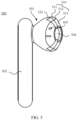
- FIG. 3 is a schematic diagram of a structure of an earphone 300.
- the earphone 300 provided in this embodiment of this application may be divided into a main body structure 301 configured to be inserted into an ear canal, and a tube structure 302 connected to the main body structure 301.
- the main body structure 301 is configured to carry most structures of the earphone 300, for example, different components such as a speaker, a driver, and an FB Mic.
- the tube structure 302 extends from the main body structure 301, and may be integrated with the main body structure 301.
- a size of the tube structure 302 may be designed to include a cable.
- the cable may include a wire extending from a power sound source (not shown) to the speaker assembly.
- the wire may carry an audio signal obtained after the driver performs audio conversion.
- Embodiment 1 of this application discloses an earphone 300, including a housing 310.
- the housing 310 is configured to carry components, cables, and the like of the earphone 300.
- the components may include a speaker assembly.
- the housing 310 includes a front cavity and a rear cavity that are separated by the speaker assembly.
- the front cavity is located on a side that is of the speaker assembly and that is a sound output direction
- the rear cavity is located on an opposite side of the sound output direction of the speaker assembly.
- a structure of the speaker assembly and the front cavity and the rear cavity that are obtained through division by using the speaker assembly are conventional settings of the earphone 300. Details are not described herein.
- the housing 310 has a clamping region 312 configured to be clamped in an ear canal of a user.
- the housing 310 is divided into a main body region 311 and a tip region 313 by the clamping region 312, and the main body region 311 and the tip region 313 are arranged on two sides of the clamping region 312.
- the tip region 313 uses a structure tapered in a direction away from the main body region 311, and a shape of the tip region 313 can allow the tip region 313 to be inserted into the ear canal.
- a main sound output hole 304 is disposed in the housing 310, and the main sound output hole 304 may be formed in the tip region 313.
- the main sound output hole 304 is located inside the ear canal, and the main sound output hole 304 is connected to the front cavity of the housing 310, and can output sound generated by the speaker assembly (in response to an audio signal) to the ear canal.
- the main sound output hole 304 may have any size and dimension suitable for implementing expected acoustic performance of the earphone 300.
- the main sound output hole 304 may be of different shapes such as oval or round.
- the clamping region 312 When the earphone 300 is worn in the ear canal, the clamping region 312 may be in close contact with the ear canal. However, because the housing 310 is usually made of a non-flexible or rigid material (such as plastic), close contact between the clamping region 312 and the ear canal may not be airtight. A gap may be caused between the clamping region 312 and the ear canal, and the gap may be used for air leakage. Because different users have different ear canals, different gaps are caused between the clamping region 312 and the ear canals. In addition, for a same user, each time the same user wears the earphone 300, an airflow leakage amount may be different due to different strength or a different position during wearing.
- airflow leakage between the clamping region 312 and the ear canal is uncontrollable, and is affected by many artificial factors.
- a difference in airflow leakage amount may cause a bad feeling for the user.
- the speaker assembly in the earphone 300 sends sound to the ear canal
- a high sound pressure level at a low frequency may appear inside the ear canal, and the high sound pressure may cause an unpleasant sound effect for the user.
- the tip region 313 of the housing 310 extends into the ear canal, a large amount of air is prevented from leaking around the tip region 313, and consequently the caused high sound pressure cannot be rapidly released.
- each sound guide channel 320 is disposed in a sidewall of the housing 310, and each sound guide channel 320 is configured to: when the earphone 300 is normally worn, connect air inside the ear canal of the user to air outside the ear canal without connecting air in the front cavity to air in the rear cavity.
- the foregoing normal wearing is a wearing manner in which the earphone can be normally used, for example, a wearing manner indicated in an existing earphone specification.
- FIG. 3 illustrates two sound guide channels 320.
- the one or more sound guide channels 320 provided in this embodiment of this application may be one sound guide channel 320, or may be two or more sound guide channels 320. All sound guide channels may be disposed in a same manner or different manners. For implementations of various sound guide channels, refer to the following descriptions.
- At least one of the one or more sound guide channels 320 is a through hole disposed in the housing 310.
- the through hole is located in the sidewall of the housing 310 and extends in the sidewall of the housing 310.
- Two ends of the through hole are respectively a first opening 321 and a second opening 322.
- the first opening 321 and the second opening 322 are located on the outer surface of the housing 310 (for example, are respectively arranged on two sides of the clamping region 312), and are configured to be respectively connected to air inside the ear canal and air outside the ear canal, so that air inside the ear canal is connected to air outside the ear canal by using the through hole in the sidewall.
- the outer surface of the housing 310 is a surface that is of the housing 310 and that faces the ear canal.
- a lower sound guide channel in the figure is used as an example.
- a first opening 321 of the sound guide channel 320 is located inside the ear canal, and a second opening 322 is located outside the ear canal.
- the first opening 321 is connected to air inside the ear canal when the earphone 300 is normally worn, and the second opening 322 is connected to air outside the ear canal when the earphone 300 is normally worn, so that the sound guide channel 320 directly connects the inside of the ear canal to the outside of the ear canal of the user.
- FIG. 4 shows a schematic diagram of an earphone during application.
- the sound guide channel 320 may extend from the tip region 313 to outside air across the clamping region 312.
- the first opening and the second opening are respectively located inside the ear canal 206 and outside the ear canal 206, and the ear canal 206 of the user is connected to outside air by using the sound guide channel 320.
- the sound guide channel 320 may implement functions of exhausting air from the ear canal 206 and outputting sound from the earphone to an outside environment of the earphone.
- the through hole in the housing is equivalent to a "tunnel" located in the housing, and air inside the ear canal of the user is connected to air outside the ear canal by using the "tunnel".
- the first opening 321 and the second opening 322 are respectively disposed on the tip region 313 and the main body region 311.
- the first opening 321 is located inside the ear canal, and the first opening 321 is not blocked by the ear canal; and the second opening 322 is located outside the ear canal, and the second opening 322 is not shielded by an auricle or an auricular concha of the ear
- the sound guide channel 320 may be divided into two parts: a first channel and a second channel, and the first channel is connected to the second channel.
- the second channel is disposed in the main body region 311, and the first channel is disposed in the tip region 313.
- the first channel is disposed in a housing part located in the tip region 313.
- the elastic sleeve is disposed in the tip region 313.
- a part of at least one of the one or more sound guide channels is disposed in the elastic sleeve.
- the first channel may be located in the elastic sleeve, so that the first opening 321 on the first channel can be directly connected to space inside the ear canal.
- the first opening 321 and the second opening 322 of the sound guide channel 320 may use different area ratios.
- an opening area S1 of the first opening 321 and an opening area S2 of the second opening 322 meet: a ratio of S1 to S2 is 0.5 to 2.
- the opening area S1 of the first opening 321 may be equal to the opening area S2 of the second opening 322, or the opening area S1 of the first opening 321 may be greater than the opening area S2 of the second opening 322.
- the opening area S1 of the first opening 321 is any proportion between 0.5 to 2, such as 0.5 times, 0.8 times, 1.1 times, 1.2 times, 1.3 times, 1.4 times, 1.5 times, or 2 times, of the opening area S2 of the second opening 322.
- 0.5 times, 0.8 times, 1.1 times, 1.2 times, 1.3 times, 1.4 times, 1.5 times, or 2 times of the opening area S2 of the second opening 322.
- the opening area S1 of the first opening 321 of the sound guide channel 320 is not less than 2 mm 2 .
- the opening area S1 of the first opening 321 may be different areas such as 2 mm 2 , 2.5 mm 2 , 3 mm 2 , 3.5 mm 2 , or 4 mm 2 , to ensure that the sound guide channel 320 has a stable leakage amount.
- both the first opening 321 and the second opening 322 of the sound guide channel 320 illustrated in FIG. 3 are oval.
- the port shape illustrated in FIG. 3 is only one specific example, and the first opening 321 and the second opening 322 may be alternatively of other shapes.
- the first opening 321 and the second opening 322 may be of different shapes, such as round, oval, square, or special-shaped.
- the first opening 321 and the second opening 322 may be of a same shape or different shapes.
- both the first opening 321 and the second opening 322 may be round; or the first opening 321 may be round, and the second opening 322 may be oval.
- a direction of the sound guide channel 320 may be disposed in different manners, for example, different shapes such as linear, curved, serpentine, or branch-shaped.
- the sound guide channel 320 can facilitate air circulation and does not hinder air.
- the first channel and the second channel each may be of different shapes such as linear, curved, serpentine, or branch-shaped, provided that it is ensured that the first channel is connected to the second channel.
- a length direction of the sound guide channel 320 may be partially parallel to an ear canal direction of the user, to facilitate leakage of air inside the ear canal.
- the length direction of the sound guide channel 320 is parallel to the ear canal, and the direction of the sound guide channel 320 may vary with the ear canal.
- a cross-section of the sound guide channel 320 may be of different shapes, such as oval, trapezoidal, round, square, or special-shaped.
- the sound guide channel 320 may be a sound guide channel 320 with a constant cross-sectional area, or may be a sound guide channel 320 with a gradient cross-sectional area.
- a cross-sectional area or shape of the sound guide channel 320 may adaptively change, to ensure smooth changing from the shape or area of the first opening 321 to the shape or area of the second opening 322 in the sound guide channel 320.
- a length of the sound guide channel 320 is not less than 3 mm.
- the length of the sound guide channel 320 indicates a linear distance between the first opening 321 and the second opening 322. That is, in this embodiment of this application, there should be a distance of a specific length between the first opening 321 and the second opening 322 of the sound guide channel 320, to ensure that when the clamping region 312 is in contact with the ear canal, the ear canal does not block the first opening 321, and the second opening 322 can be exposed to an outside environment and is not shielded by another structure of the ear, thereby ensuring smoothness of the sound guide channel 320.
- the distance between the first opening 321 and the second opening 322 may be different distances such as 3 mm, 3.5 mm, 4 mm, 4.5 mm, or 5 mm.
- protective meshes may be disposed for the first opening 321 and the second opening 322.
- the protective mesh is a porous structure, so that an outside impurity can be prevented from entering the sound guide channel 320, thereby ensuring reliability of the sound guide channel 320.
- the first opening 321 may be disposed on the surface that is of the housing 310 and that faces the ear canal, to conveniently connect the inside of the ear canal to the outside of the ear canal, so that air inside the ear canal can enter the sound guide channel 320 by using the first opening 321. It should be understood that, that the first opening 321 is disposed on the surface that is of the housing 310 and that faces the ear canal is only one specific example of a disposition position of the first opening 321. The first opening 321 provided in this embodiment of this application only needs to be disposed at a position that is not shielded by the ear canal.
- the first opening 321 may be disposed at a position connected to the main sound output hole 304, so that an airflow output from the main sound output hole 304 can directly enter the sound guide channel 320 by using the first opening 321, thereby improving an air leakage effect.
- the first opening 321 is connected to the main sound output hole 304, so that the ear canal is also prevented from blocking the first opening 321, thereby ensuring airflow leakage stability of the sound guide channel 320.
- an opening direction of the first opening 321 may be the same as an opening direction of the main sound output hole 304, so that the ear canal can also be prevented from blocking the first opening 321.
- the first opening 321 is formed in a sidewall (the sidewall of the housing 310) around the main sound output hole.
- the sound guide channel 320 when the sound guide channel 320 is disposed, a stable airflow exhaust channel can be formed without impact caused by cooperation between the clamping region 312 and a sidewall of the ear canal 206. Therefore, the sound guide channel 320 can be used as a controlled sound guide port. A size and a shape of the sound guide channel 320 may be selected to achieve an acoustically satisfactory effect. In addition, the sound guide channel 320 can be used as a controlled sound guide port, so that consistent effects can be maintained at all times a same user wears the earphone, and always consistent air leakage amounts can also be implemented between different users.
- sound pressure in the earphone can be exposed to an outside surrounding environment, so that a second sound field emitted by the speaker has a stable characteristic, to conveniently calibrate the earphone to modify an acoustic response of the earphone, and improve SP response consistency, thereby improving overall listening performance and noise cancellation performance of the earphone.
- FIG. 5 is a schematic diagram of a structure of another earphone according to an embodiment of this application.
- a sound guide channel of the earphone shown in FIG. 5 is a groove 323, that is, at least one of one or more sound guide channels is a groove 323 disposed on an outer surface of a housing 310.
- An opening at one end of the groove 323 is connected to air inside an ear canal when the earphone 300 is normally worn, and an opening at the other end of the groove 323 is connected to air outside the ear canal when the earphone 300 is normally worn.
- the groove 323 is disposed on the outer surface (a surface that is of the housing 310 and that faces the ear canal) of the housing 310, and extends from a tip region 313 of the housing 310 to a main body region 311.
- the groove 323 may use a linear groove. It should be understood that a shape of the groove 323 provided in this embodiment of this application is not limited to the linear groove 323 shown in FIG. 5 . Different shapes of grooves such as a curved groove or a groove of a water drop shape may be alternatively used.
- the groove 323 When the groove 323 is used as the sound guide channel, the groove 323 may be connected to a longer side of a main sound output hole 304, so that the groove 323 can be prevented from being shielded by the ear canal, thereby ensuring air leakage stability.
- connection between a sound guide channel inside the ear canal and a sound guide channel outside the ear canal can also be implemented, to achieve a stable improvement effect for a sound effect of the earphone.
- linear correlation between an SP response and a DRP response is involved, to obtain a relatively large gain.
- an opening area of the sound guide channel is increased, and the sound guide channel is prevented from being shielded by the ear canal.
- a depth or the shape of the groove 323 should ensure that when the earphone is worn in an ear, the groove 323 is not blocked by a part that is of the ear and that is pushed into the groove 323.
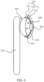
- FIG. 6 is a schematic diagram of a structure of an earphone according to an embodiment of this application.
- a sound guide channel shown in FIG. 6 is in a combination form of a groove 324 and a through hole 325.
- the through hole 325 is connected to the groove 324 to form the sound guide channel.
- at least one of one or more sound guide channels includes a first channel group and a second channel group.
- the first channel group includes at least one first channel, such as one, two, or three first channels.
- the first channel is a groove 324 disposed on an outer surface of a housing.
- the second channel group includes at least one second channel, such as one, two, or three second channels.
- the second channel is a through hole 325 disposed in a sidewall of the housing.
- the first channel group is connected to the second channel group, that is, the groove 324 is connected to the through hole 325.
- An opening at one end of a combined channel including the first channel group and the second channel group is connected to air inside an ear canal when the earphone is normally worn, and an opening at the other end of the combined channel is connected to air outside the ear canal when the earphone is normally worn.
- the groove 324 is located in a tip region 313 of the housing 310, and the through hole 325 is located in a main body region of the housing 310.
- An opening at one end of the through hole 325 is located in a sidewall of the groove 324, so that the groove 324 and the through hole 325 form the sound guide channel.
- FIG. 10 is a schematic diagram of a structure of an earphone according to an embodiment of this application.
- a sound guide channel of the earphone shown in FIG. 7 is a through hole, and the through hole includes three ports: a first opening 321, a second opening 322, and a third opening 326.
- the first opening 321, the second opening 322, and the third opening 326 are connected to each other.
- the second opening 322 is located in a main body region, and the second opening 322 is located outside an ear canal of a user when the earphone is worn to the user.
- the first opening 321 and the third opening 326 are located in a tip region, and the first opening 321 and the third opening 326 may be separately located at different positions.
- both the first opening 321 and the third opening 326 are located inside the ear canal.
- a stable air channel port may be added by using the added third opening 326, so that when the first opening 321 is shielded, stable air leakage can be ensured by using the third opening 326.
- the sound guide channel may be branch-shaped.
- the sound guide channel may include a first channel, a second channel, and a third channel.
- the first opening 321 is located in the first channel
- the second opening 322 is located in the second channel
- the third opening 326 is located in the third channel.
- the first opening 321, the second opening 322, and the third opening 326 are connected through connection between the first channel, the second channel, and the third channel.
- the third opening 326 is connected to a front cavity 314 of a housing 310.
- sound generated by a speaker assembly can directly flow to the second opening 322 by using the third opening 326, to implement air leakage.
- the third opening 326 when the third opening 326 is disposed in the front cavity 314, the third opening 326 can be prevented from being shielded by the ear canal, thereby ensuring that the sound guide channel can have a stable leakage amount.
- this embodiment describes another implementation of the sound guide channel.
- a conduit 327 shown in FIG. 8 at least one of one or more sound guide channels may be a conduit 327 disposed in a sidewall of a housing 310.
- conduits 327 refer to the descriptions of the other types of sound guide channels in the foregoing embodiments. Details are not described herein.
- the conduit 327 has a first opening 329 and a second opening 328.
- the first opening 329 is connected to air inside an ear canal when the earphone is normally worn, and the second opening 328 is connected to air outside the ear canal when the earphone is normally worn.
- the conduit 327 may be understood as an alternative structure of the through hole in Embodiment 1.
- conduit 327 when the conduit 327 is specifically disposed, the conduit 327 may be partially buried in the housing 310 and partially exposed from the housing 310, or may be completely buried in the housing 310. This is not specifically limited herein.
- the conduit 327 may be a conduit 327 made of a soft material or a conduit 327 made of a hard material.
- the conduit 327 may use a material such as plastic or silicone, or the conduit 327 may use a material consistent with a material of the housing 310.
- a sound pickup channel is described based on the earphones illustrated in the foregoing embodiments.
- a specific structure includes: a microphone (feedback microphone) disposed in a front cavity and a sound pickup channel connected to the microphone.
- a microphone feedback microphone
- An end of the sound pickup channel is connected to the microphone, the other end of the sound pickup channel includes a sound pickup hole 305, and the sound pickup hole 305 is disposed on a surface that is of a housing 310 and that faces the ear canal.
- the sound pickup hole 305 usually needs to be as close to a speaker assembly as possible, to obtain a direct SP response.
- the in-ear earphone because the in-ear earphone is sealed with a rubber sleeve, a front cavity is not prone to air leakage, and correlation between an SP response and a DRP response is usually good.
- a semi-in-ear earphone provided in this embodiment of this application, due to air leakage of the earphone, linear correlation between an SP response in front of a speaker and a response at a DRP becomes poor.
- the sound pickup hole 305 is disposed on a first side of a clamping region 312 on the housing.
- the first side is a side close to the inside of the ear canal 206 relative to the clamping region 312 on the housing.
- the sound pickup hole 305 picks up an SP response obtained after leakage, and an SP response at a DRP is also a response obtained after leakage, so that a better SP response and a better DRP response can be obtained.
- the sound pickup hole 305 may be disposed at different positions when being disposed.
- the sound pickup hole 305 may be disposed on an outer surface that is of the housing 310 and that faces the ear canal. As shown in FIG. 3 , the sound pickup hole 305 is disposed in a tip region 313 of the housing 310. When the earphone is worn to the user, the sound pickup hole 305 should not be shielded by the ear canal.
- the sound pickup hole 305 may be located in different structures when being located in the tip region 313 of the housing 310.
- the sound pickup hole 305 may be located on an outer surface of the tip region 313, the sound pickup hole 305 may be located in a sound guide channel, or the sound pickup hole 305 is located in a main sound output hole 304.
- linear correlation between an FB response and a DRP response can be improved, and a binaural recording effect can also be improved.
- the feedback microphone When the feedback microphone is located in the housing 310, the feedback microphone may be placed at the tip region 313 or another position of the earphone.
- the feedback microphone is disposed on an inner surface of the housing 310, to facilitate disposition of the feedback microphone and also facilitate data collection.
- a sound pickup surface of the feedback microphone faces the sound pickup hole 305, and may receive sound received by the sound pickup hole 305.
- the sound pickup hole 305 may be connected to the microphone in different manners.
- the sound pickup hole 305 may be connected to the feedback microphone by using the foregoing sound pickup channel, or may be connected to the feedback microphone by using another tubular structure, thereby improving a pickup sound effect of the feedback microphone.
- FIG. 9 is a schematic diagram of placement of an earphone in an ear canal according to an embodiment of this application.
- a speaker assembly is located in a housing, sound emitted by the speaker assembly is provided for an ear canal 206 by using a front cavity and a main sound output hole of a tip region, and sound is received by an eardrum. A part of the sound is further leaked to outside air by using a gap 406 between the earphone and the ear canal 206. This part of leakage is greatly correlated with wearing.
- a sound guide channel 320 achieves a fixed leakage amount, and is not affected by a degree of wearing looseness. This application does not show a structure of the conventional earphone.
- the conventional earphone for comparison may be considered as a structure in which the sound guide channel 320 is removed from the earphone shown in FIG. 9 .
- the following provides descriptions by marking, in the earphone shown in FIG. 9 , detection positions of the conventional earphone and the earphone provided in this embodiment of this application.
- a first position 402 is an SP response position of the conventional earphone (having no sound guide channel)
- a second position 403 is an SP response position of the earphone in the solutions of this application
- a third position 404 is a DRP response position.
- a leakage degree of a gap between the earphone and an ear is different based on a different degree of wearing looseness.
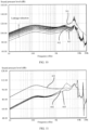
- an SP position response of the first position 402 a DRP position response of the third position 404, and an SP position response of the second position 403 are separately observed, to obtain three groups of frequency response curves shown in FIG. 10 : a first frequency response curve 501, a second frequency response curve 502, and a third frequency response curve 503.
- a vertical coordinate is a sound pressure level (unit: dB)
- a horizontal coordinate is a frequency (unit: Hz)
- the three frequency response curves are frequency response curves of the conventional earphone at the three positions. It can be learned from FIG. 10 that, when there is no sound guide channel, all the three frequency response curves have extremely large deviation from linearity, and there is no linear correlation between the three frequency response curves.
- a vertical coordinate is a sound pressure level (unit: dB), and a horizontal coordinate is a frequency (unit: Hz).
- a fourth frequency response curve 601 obtained based on a first position response is greatly improved in consistency, but is not correlated with a fifth frequency response curve 602 obtained based on a third position response; and a sixth frequency response curve 603 obtained based on a second position response and the fifth frequency response curve 602 are completely linearly correlated, and almost overlap in a low frequency part.
- the mobile terminal may be a common communicable mobile terminal such as a notebook computer, a tablet computer, a mobile phone, or an intelligent wearable device.
- the mobile terminal includes a body and any one of the foregoing earphones.
- the body and the earphone may be connected through wireless communication, for example, by using Bluetooth.
- an environment inside the ear canal may be connected to an environment outside the ear canal by using the sound guide channel disposed in the housing, so that sound pressure inside the ear canal can be exposed or exhausted to a surrounding environment outside the earphone. This reduces pre ssure inside the ear canal, thereby improvising sound experience of the user.
Landscapes
- Physics & Mathematics (AREA)
- Engineering & Computer Science (AREA)
- Acoustics & Sound (AREA)
- Signal Processing (AREA)
- Headphones And Earphones (AREA)
Applications Claiming Priority (3)
| Application Number | Priority Date | Filing Date | Title |
|---|---|---|---|
| CN202010900041 | 2020-08-31 | ||
| CN202110988228.6A CN114125622B (zh) | 2020-08-31 | 2021-08-26 | 一种耳机及移动终端 |
| PCT/CN2021/115741 WO2022042747A1 (zh) | 2020-08-31 | 2021-08-31 | 一种耳机及移动终端 |
Publications (2)
| Publication Number | Publication Date |
|---|---|
| EP4192029A1 true EP4192029A1 (de) | 2023-06-07 |
| EP4192029A4 EP4192029A4 (de) | 2024-01-17 |
Family
ID=80354713
Family Applications (1)
| Application Number | Title | Priority Date | Filing Date |
|---|---|---|---|
| EP21860579.8A Pending EP4192029A4 (de) | 2020-08-31 | 2021-08-31 | Ohrhörer und mobiles endgerät |
Country Status (3)
| Country | Link |
|---|---|
| US (1) | US12432479B2 (de) |
| EP (1) | EP4192029A4 (de) |
| WO (1) | WO2022042747A1 (de) |
Families Citing this family (2)
| Publication number | Priority date | Publication date | Assignee | Title |
|---|---|---|---|---|
| US11877110B2 (en) * | 2022-01-13 | 2024-01-16 | Bose Corporation | Flow relief features embedded in cosmetic surface of wearables |
| CN115942181B (zh) * | 2023-02-27 | 2025-12-12 | 广东小天才科技有限公司 | 耳机壳体以及耳机 |
Family Cites Families (15)
| Publication number | Priority date | Publication date | Assignee | Title |
|---|---|---|---|---|
| WO2018127263A2 (en) * | 2017-01-03 | 2018-07-12 | Lizn Aps | Speech intelligibility enhancing system |
| GB2486268B (en) * | 2010-12-10 | 2015-01-14 | Wolfson Microelectronics Plc | Earphone |
| CN102761799A (zh) * | 2011-04-27 | 2012-10-31 | 鸿富锦精密工业(深圳)有限公司 | 耳机 |
| KR101091560B1 (ko) * | 2011-11-04 | 2011-12-13 | 필스전자 주식회사 | 외부음 유입형 이어폰 |
| US9082388B2 (en) | 2012-05-25 | 2015-07-14 | Bose Corporation | In-ear active noise reduction earphone |
| US8971561B2 (en) | 2012-06-20 | 2015-03-03 | Apple Inc. | Earphone having a controlled acoustic leak port |
| CN105589506B (zh) | 2016-02-29 | 2017-10-17 | 华为技术有限公司 | 功率跟踪方法、装置及光伏发电系统 |
| CN105959856A (zh) * | 2016-07-15 | 2016-09-21 | 张基文 | 耳机 |
| CN206422888U (zh) | 2017-01-25 | 2017-08-18 | 潍坊歌尔电子有限公司 | 降噪耳机 |
| JP6841055B2 (ja) | 2017-01-27 | 2021-03-10 | 株式会社Jvcケンウッド | イヤホン |
| US10257602B2 (en) * | 2017-08-07 | 2019-04-09 | Bose Corporation | Earbud insertion sensing method with infrared technology |
| EP3503572B1 (de) * | 2017-12-20 | 2023-02-08 | ams AG | Zur rauschunterdrückung fähige audiovorrichtung und rauschunterdrückungssystem |
| US10771886B2 (en) * | 2019-01-11 | 2020-09-08 | Evga Corporation | Headphone structure for extending and enhancing resonance |
| EP3957079A1 (de) * | 2019-06-12 | 2022-02-23 | Huawei Technologies Co., Ltd. | Kopfhörer mit belüftungsanordnung |
| CN210274477U (zh) * | 2019-10-18 | 2020-04-07 | 深圳市本军科技有限公司 | 具有定向传音功能的耳机 |
-
2021
- 2021-08-31 WO PCT/CN2021/115741 patent/WO2022042747A1/zh not_active Ceased
- 2021-08-31 EP EP21860579.8A patent/EP4192029A4/de active Pending
-
2023
- 2023-02-27 US US18/174,717 patent/US12432479B2/en active Active
Also Published As
| Publication number | Publication date |
|---|---|
| EP4192029A4 (de) | 2024-01-17 |
| US12432479B2 (en) | 2025-09-30 |
| WO2022042747A1 (zh) | 2022-03-03 |
| US20230224620A1 (en) | 2023-07-13 |
Similar Documents
| Publication | Publication Date | Title |
|---|---|---|
| JP3746810B2 (ja) | スープラオーラルヘッドホン | |
| US8170249B2 (en) | Hearing aid having two receivers each amplifying a different frequency range | |
| JP5695703B2 (ja) | 音響チューニングメカニズムを有するイヤホン | |
| US12432479B2 (en) | Earphone and mobile terminal | |
| CN114125622B (zh) | 一种耳机及移动终端 | |
| US12317021B2 (en) | Earphone | |
| US11540043B1 (en) | Active noise reduction earbud | |
| US20090180657A1 (en) | Personal communication method and apparatus with reduced audio leakage | |
| EP3544313A1 (de) | Tonausgabevorrichtung und steuerungsverfahren für eine tonausgabevorrichtung | |
| CN211152190U (zh) | 一种半入耳式主动降噪耳机 | |
| US20220377447A1 (en) | Wireless headset with improved wind noise resistance | |
| JP2019145964A (ja) | イヤホン | |
| CN216626007U (zh) | 一种耳机及移动终端 | |
| KR101038703B1 (ko) | 음향 가이드 튜브를 구비한 이어폰 | |
| WO2026021337A1 (zh) | 耳机 | |
| CN221177898U (zh) | 一种开放型耳机 | |
| CN213368080U (zh) | 可更换耳塞的耳机 | |
| CN215871779U (zh) | 一种半入耳式耳机 | |
| US12047725B2 (en) | Adaptive eartip for true wireless stereo headsets | |
| WO2022116765A1 (zh) | 一种耳机及移动终端 | |
| CN208707900U (zh) | 一种降噪耳机 | |
| CN219802547U (zh) | 一种气传导耳机 | |
| CN221429084U (zh) | 一种通话音质高的耳夹式耳机 | |
| CN118104251B (zh) | 开放式耳机 | |
| CN216752042U (zh) | 一种耳机和耳机组件 |
Legal Events
| Date | Code | Title | Description |
|---|---|---|---|
| STAA | Information on the status of an ep patent application or granted ep patent |
Free format text: STATUS: THE INTERNATIONAL PUBLICATION HAS BEEN MADE |
|
| PUAI | Public reference made under article 153(3) epc to a published international application that has entered the european phase |
Free format text: ORIGINAL CODE: 0009012 |
|
| STAA | Information on the status of an ep patent application or granted ep patent |
Free format text: STATUS: REQUEST FOR EXAMINATION WAS MADE |
|
| 17P | Request for examination filed |
Effective date: 20230302 |
|
| AK | Designated contracting states |
Kind code of ref document: A1 Designated state(s): AL AT BE BG CH CY CZ DE DK EE ES FI FR GB GR HR HU IE IS IT LI LT LU LV MC MK MT NL NO PL PT RO RS SE SI SK SM TR |
|
| DAV | Request for validation of the european patent (deleted) | ||
| DAX | Request for extension of the european patent (deleted) | ||
| A4 | Supplementary search report drawn up and despatched |
Effective date: 20231218 |
|
| RIC1 | Information provided on ipc code assigned before grant |
Ipc: H04R 1/10 20060101AFI20231212BHEP |
|
| STAA | Information on the status of an ep patent application or granted ep patent |
Free format text: STATUS: EXAMINATION IS IN PROGRESS |
|
| 17Q | First examination report despatched |
Effective date: 20250909 |