EP4192080A1 - Multilink-kommunikationsverfahren, dienst- und link-mapping-verfahren und vorrichtung - Google Patents
Multilink-kommunikationsverfahren, dienst- und link-mapping-verfahren und vorrichtung Download PDFInfo
- Publication number
- EP4192080A1 EP4192080A1 EP21857350.9A EP21857350A EP4192080A1 EP 4192080 A1 EP4192080 A1 EP 4192080A1 EP 21857350 A EP21857350 A EP 21857350A EP 4192080 A1 EP4192080 A1 EP 4192080A1
- Authority
- EP
- European Patent Office
- Prior art keywords
- link
- traffic
- mapping
- information
- message
- Prior art date
- Legal status (The legal status is an assumption and is not a legal conclusion. Google has not performed a legal analysis and makes no representation as to the accuracy of the status listed.)
- Granted
Links
Images


Classifications
-
- H—ELECTRICITY
- H04—ELECTRIC COMMUNICATION TECHNIQUE
- H04W—WIRELESS COMMUNICATION NETWORKS
- H04W72/00—Local resource management
- H04W72/12—Wireless traffic scheduling
- H04W72/1263—Mapping of traffic onto schedule, e.g. scheduled allocation or multiplexing of flows
-
- H—ELECTRICITY
- H04—ELECTRIC COMMUNICATION TECHNIQUE
- H04W—WIRELESS COMMUNICATION NETWORKS
- H04W24/00—Supervisory, monitoring or testing arrangements
- H04W24/02—Arrangements for optimising operational condition
-
- H—ELECTRICITY
- H04—ELECTRIC COMMUNICATION TECHNIQUE
- H04W—WIRELESS COMMUNICATION NETWORKS
- H04W76/00—Connection management
- H04W76/10—Connection setup
- H04W76/15—Setup of multiple wireless link connections
-
- H—ELECTRICITY
- H04—ELECTRIC COMMUNICATION TECHNIQUE
- H04W—WIRELESS COMMUNICATION NETWORKS
- H04W28/00—Network traffic management; Network resource management
- H04W28/02—Traffic management, e.g. flow control or congestion control
- H04W28/0252—Traffic management, e.g. flow control or congestion control per individual bearer or channel
-
- H—ELECTRICITY
- H04—ELECTRIC COMMUNICATION TECHNIQUE
- H04W—WIRELESS COMMUNICATION NETWORKS
- H04W72/00—Local resource management
- H04W72/20—Control channels or signalling for resource management
-
- H—ELECTRICITY
- H04—ELECTRIC COMMUNICATION TECHNIQUE
- H04W—WIRELESS COMMUNICATION NETWORKS
- H04W84/00—Network topologies
- H04W84/02—Hierarchically pre-organised networks, e.g. paging networks, cellular networks, WLAN [Wireless Local Area Network] or WLL [Wireless Local Loop]
- H04W84/10—Small scale networks; Flat hierarchical networks
- H04W84/12—WLAN [Wireless Local Area Networks]
-
- H—ELECTRICITY
- H04—ELECTRIC COMMUNICATION TECHNIQUE
- H04W—WIRELESS COMMUNICATION NETWORKS
- H04W76/00—Connection management
- H04W76/10—Connection setup
- H04W76/11—Allocation or use of connection identifiers
-
- H—ELECTRICITY
- H04—ELECTRIC COMMUNICATION TECHNIQUE
- H04W—WIRELESS COMMUNICATION NETWORKS
- H04W76/00—Connection management
- H04W76/10—Connection setup
- H04W76/12—Setup of transport tunnels
-
- H—ELECTRICITY
- H04—ELECTRIC COMMUNICATION TECHNIQUE
- H04W—WIRELESS COMMUNICATION NETWORKS
- H04W76/00—Connection management
- H04W76/10—Connection setup
- H04W76/19—Connection re-establishment
-
- H—ELECTRICITY
- H04—ELECTRIC COMMUNICATION TECHNIQUE
- H04W—WIRELESS COMMUNICATION NETWORKS
- H04W76/00—Connection management
- H04W76/30—Connection release
- H04W76/32—Release of transport tunnels
-
- H—ELECTRICITY
- H04—ELECTRIC COMMUNICATION TECHNIQUE
- H04W—WIRELESS COMMUNICATION NETWORKS
- H04W76/00—Connection management
- H04W76/30—Connection release
- H04W76/34—Selective release of ongoing connections
Definitions
- This application relates to the field of communication technologies, and in particular, to a multi-link communication method, a traffic-to-link mapping method, and a device.
- multi-link device multi-link device
- Multi-link establishment needs to be performed before MLDs communicate with each other. For example, a first multi-link device sends an association request frame to a second multi-link device to perform multi-link establishment, where the association request frame carries information about a link, supported by the first multi-link device, on which the first multi-link device wants to establish multi-link communication.
- an MLD may not have a communication requirement on each link supported by the MLD at the beginning. If the MLD establishes multi-link communication on all links supported by the MLD at the beginning, link resource utilization is low. In a subsequent communication process, the MLD may further have a requirement for updating a communication link. However, at the beginning, the multi-link device provides only information about a link on which the multi-link device wants to establish multi-link communication. This cannot meet the requirement for updating the communication link. It can be learned that multi-link communication in the conventional technology has a technical problem that flexibility is poor and an actual application requirement cannot be met.
- Embodiments of this application provide a multi-link communication method, a traffic-to-link mapping method, and a device, so that flexibility of multi-link communication performed by a multi-link device can be improved, and a requirement of dynamically updating a communication link by the multi-link device can be met.
- traffic transmission can be more flexibly managed, and quality of service of traffic can be improved.
- a multi-link communication method includes: A first multi-link device receives a first request message sent by a second multi-link device, where the first request message carries identifiers of at least two links and first indication information of each of the at least two links, the first indication information indicates an operation type of the link, the operation type includes establishing multi-link communication, and further includes providing only link information or not establishing multi-link communication.
- the first multi-link device sends a first response message to the second multi-link device, where the first response message carries the identifiers of the at least two links and second indication information of each of the at least two links, and the second indication information indicates a status of the link.
- the first request message carries the first indication information
- the first response message carries the second indication information, so that during multi-link establishment, the multi-link device may select, based on a requirement, to establish multi-link communication on a part of links supported by the multi-link device. This can improve flexibility of multi-link communication performed by the multi-link device.
- the operation type further includes: adding a link to a multi-link communication link; and/or deleting a link from the multi-link communication link.
- the first request message carries the first indication information
- the first response message carries the second indication information, so that after completing multi-link establishment, the multi-link device may add a link to or delete a link from the established multi-link communication link based on a communication requirement. This can further improve flexibility of multi-link communication performed by the multi-link device, and better meet a requirement of dynamically updating the communication link by the multi-link device.
- the status includes any one or more of the following items: the multi-link communication is successfully established; the multi-link communication fails to be established; only the link information is provided or the multi-link communication is not established; the link is successfully added; the link fails to be added; the link is successfully deleted; or the link fails to be deleted.
- the first indication information and/or the second indication information are/is carried in a first preset field in a multi-link information element.
- This implementation is simple and easy to implement.
- a first value of the first preset field indicates that the operation type is establishing multi-link communication
- a second value of the first preset field indicates that the operation type is providing only link information or not establishing multi-link communication.
- a first value of the first preset field indicates that the status is that the multi-link communication is successfully established
- a second value of the first preset field indicates that the status is that the multi-link communication fails to be established
- a third value of the first preset field indicates that the status is that only the link information is provided or the multi-link communication is not established.
- values of the first preset field may each indicate a different meaning.
- the meaning indicated by the value of the first preset field may be determined based on a type (namely, the association request frame and the association response frame) of a frame in which the first preset field is located and based on the value of the first preset field, so that bits occupied by the first preset field can be reduced.
- a value of the first preset field includes any one or more of the following items:
- a value of the first preset field may indicate a same meaning, and the meaning indicated by the value of the first preset field may be directly determined based on the value of the first preset field. This can reduce complexity of identifying the first preset field by the multi-link device.
- a first value of the first preset field indicates that the operation type is adding a link to a multi-link communication link
- a second value of the first preset field indicates that the operation type is deleting a link from the multi-link communication link.
- a first value of the first preset field indicates that the status is that the link is successfully added
- a second value of the first preset field indicates that the status is that the link fails to be added
- a third value of the first preset field indicates that the status is that the link is successfully deleted
- a fourth value of the first preset field indicates that the status is that the link fails to be deleted.
- values of the first preset field may each indicate a different meaning.
- the meaning indicated by the value of the first preset field may be determined based on a type (namely, the reassociation request frame and the reassociation response frame) of a frame in which the first preset field is located and based on the value of the first preset field, so that bits occupied by the first preset field can be reduced.
- a value of the first preset field includes any one or more of the following items:
- a value of the first preset field may indicate a same meaning, and the meaning indicated by the value of the first preset field may be directly determined based on the value of the first preset field. This can reduce complexity of identifying the first preset field by the multi-link device.
- a value of the first preset field includes any one or more of the following items:
- a value of the first preset field may indicate a same meaning, and the meaning indicated by the value of the first preset field may be directly determined based on the value of the first preset field. This can further reduce complexity of identifying the first preset field by the multi-link device.
- the first request message if the operation type is establishing multi-link communication, not establishing multi-link communication, providing only the link information, or adding the link to the multi-link communication link, the first request message further carries capability information of a station. Alternatively, if the operation type is deleting the link from the multi-link communication link, the first request message does not carry capability information of a station.
- the first request message does not carry capability information of a station. This can reduce resource overheads while ensuring reliability of the solution.
- the multi-link information element further carries information about a new link of an access point device.
- a multi-link device MLD common information field of the multi-link information element carries third indication information, indicating that the multi-link information element carries information about the new link.
- the multi-link device starts a new link based on a communication requirement, and notifies another multi-link device in time, to further improve flexibility of multi-link communication, and better meet a requirement of dynamically updating a communication link by the multi-link device.
- the information about the new link is carried in each beacon frame of N consecutive beacon frames, and N is a positive integer.
- a multi-link communication method includes: A first multi-link device receives a first request message sent by a second multi-link device, where the first request message carries identifiers of at least two links and first indication information of each of the at least two links, the first indication information indicates an operation type of the link, the operation type includes adding a link to a multi-link communication link, and further includes providing only link information or not establishing multi-link communication.
- the first multi-link device sends a first response message to the second multi-link device, where the first response message carries the identifiers of the at least two links and second indication information of each of the at least two links, and the second indication information indicates a status of the link.
- the first request message carries the first indication information
- the first response message carries the second indication information
- the multi-link device adds the link to the established multi-link communication link based on a requirement.
- information about another link that does not need to establish multi-link communication is further provided, so that the multi-link device subsequently adds a link based on a requirement. This can improve flexibility of multi-link communication performed by the multi-link device.
- the operation type further includes: establishing multi-link communication; and/or deleting a link from the multi-link communication link.
- the status includes any one or more of the following items: the multi-link communication is successfully established; the multi-link communication fails to be established; only the link information is provided or the multi-link communication is not established; the link is successfully added; the link fails to be added; the link is successfully deleted; or the link fails to be deleted.
- a multi-link communication method includes: A first multi-link device receives a first request message sent by a second multi-link device, where the first request message carries identifiers of at least two links and first indication information of each of the at least two links, the first indication information indicates an operation type of the link, the operation type includes deleting a link to a multi-link communication link, and further includes providing only link information or not establishing multi-link communication.
- the first multi-link device sends a first response message to the second multi-link device, where the first response message carries the identifiers of the at least two links and second indication information of each of the at least two links, and the second indication information indicates a status of the link.
- the first request message carries the first indication information
- the first response message carries the second indication information, so that the multi-link device deletes the link from the established multi-link communication link based on a requirement.
- information about another link that does not need to establish multi-link communication is further provided, so that the multi-link device subsequently adds a link based on a requirement. This can improve flexibility of multi-link communication performed by the multi-link device.
- the operation type further includes: establishing multi-link communication; and/or adding a link to the multi-link communication link.
- the status includes any one or more of the following items: the multi-link communication is successfully established; the multi-link communication fails to be established; only the link information is provided or the multi-link communication is not established; the link is successfully added; the link fails to be added; the link is successfully deleted; or the link fails to be deleted.
- a multi-link communication method includes: A second multi-link device sends a first request message to a first multi-link device, where the first request message carries identifiers of at least two links and first indication information of each of the at least two links, the first indication information indicates an operation type of the link, the operation type includes establishing multi-link communication, and further includes providing only link information or not establishing multi-link communication.
- the second multi-link device receives a first response message from the first multi-link device, where the first response message carries the identifiers of the at least two links and second indication information of each of the at least two links, and the second indication information indicates a status of the link.
- the operation type further includes: adding a link to a multi-link communication link; and/or deleting a link from the multi-link communication link.
- the status includes any one or more of the following items: the multi-link communication is successfully established; the multi-link communication fails to be established; only the link information is provided or the multi-link communication is not established; the link is successfully added; the link fails to be added; the link is successfully deleted; or the link fails to be deleted.
- the first indication information and/or the second indication information are/is carried in a first preset field in a multi-link information element.
- a first value of the first preset field indicates that the operation type is establishing multi-link communication
- a second value of the first preset field indicates that the operation type is providing only link information or not establishing multi-link communication.
- a first value of the first preset field indicates that the status is that the multi-link communication is successfully established
- a second value of the first preset field indicates that the status is that the multi-link communication fails to be established
- a third value of the first preset field indicates that the status is that only the link information is provided or the multi-link communication is not established.
- a value of the first preset field includes any one or more of the following items:
- the first request message if the operation type is establishing multi-link communication, not establishing multi-link communication, providing only the link information, or adding the link to the multi-link communication link, the first request message further carries capability information of a station. Alternatively, if the operation type is deleting the link from the multi-link communication link, the first request message does not carry capability information of a station.
- the multi-link information element further carries information about a new link of an access point device.
- a multi-link device MLD common information field of the multi-link information element carries third indication information, indicating that the multi-link information element carries information about the new link.
- the information about the new link is carried in each beacon frame of N consecutive beacon frames, and N is a positive integer.
- a multi-link communication method includes: A second multi-link device sends a first request message to a first multi-link device, where the first request message carries identifiers of at least two links and first indication information of each of the at least two links, the first indication information indicates an operation type of the link, the operation type includes adding a link to a multi-link communication link, and further includes providing only link information or not establishing multi-link communication.
- the second multi-link device receives a first response message from the first multi-link device, where the first response message carries the identifiers of the at least two links and second indication information of each of the at least two links, and the second indication information indicates a status of the link.
- the operation type further includes: establishing multi-link communication; and/or deleting a link from the multi-link communication link.
- the status includes any one or more of the following items: the multi-link communication is successfully established; the multi-link communication fails to be established; only the link information is provided or the multi-link communication is not established; the link is successfully added; the link fails to be added; the link is successfully deleted; or the link fails to be deleted.
- a multi-link communication method includes: A second multi-link device sends a first request message to a first multi-link device, where the first request message carries identifiers of at least two links and first indication information of each of the at least two links, the first indication information indicates an operation type of the link, the operation type includes deleting a link to a multi-link communication link, and further includes providing only link information or not establishing multi-link communication.
- the second multi-link device receives a first response message from the first multi-link device, where the first response message carries the identifiers of the at least two links and second indication information of each of the at least two links, and the second indication information indicates a status of the link.
- the operation type further includes: establishing multi-link communication; and/or adding a link to the multi-link communication link.
- the status includes any one or more of the following items: the multi-link communication is successfully established; the multi-link communication fails to be established; only the link information is provided or the multi-link communication is not established; the link is successfully added; the link fails to be added; the link is successfully deleted; or the link fails to be deleted.
- a multi-link communication method includes: A first multi-link device receives a second message from a second multi-link device, where the second message carries traffic-to-link mapping information. The first multi-link device establishes or updates a traffic-to-link mapping relationship based on the mapping information.
- the second multi-link device adds the traffic-to-link mapping information to the second message, so that the first multi-link device can further establish a traffic-to-link mapping relationship during multi-link establishment, or update the traffic-to-link mapping relationship after completing multi-link establishment, to manage traffic transmission more flexibly and improve quality of service.
- the second message further carries fourth indication information, and the fourth indication information indicates a second mode used for negotiating a traffic identifier-to-link mapping.
- the method further includes: The first multi-link device sends a third message to the second multi-link device, where the third message carries fifth indication information, and the fifth indication information indicates a first mode used for negotiating a traffic identifier-to-link mapping.
- the first multi-link device and the second multi-link device may negotiate the traffic identifier-to-link mapping, so that flexibility of traffic transmission can be further improved.
- the first mode is: a traffic-to-link mapping is requested to be established, but a specific traffic-to-link mapping method is not carried; a traffic-to-link mapping is requested to be established, a suggested mapping method is carried, and a responder is allowed to modify a mapping relationship in a response frame; or a traffic-to-link mapping is requested to be established, a demanded mapping method is carried, and a responder is not allowed to modify a mapping relationship in a response frame.
- the second mode is: the traffic-to-link mapping is successfully established, and a final mapping method is carried; the traffic-to-link mapping is not successfully established, and the suggested mapping method is carried; the traffic-to-link mapping is not successfully established, the demanded mapping method is carried, and if a requester sends a request again, the mapping can be successfully established only by using the mapping method; or the traffic-to-link mapping fails to be established.
- the second message is an association response frame or an EHT action frame.
- the second message is a broadcast message.
- the second multi-link device may directly broadcast traffic-to-link mapping information, to further improve flexibility of traffic transmission.
- the method before the first multi-link device receives the second message from the second multi-link device, the method further includes: The first multi-link device sends a fourth message to the second multi-link device, where the fourth message carries seventh indication information, and the seventh indication information indicates that the first multi-link device supports broadcast traffic-to-link mapping information.
- the first multi-link device notifies the second multi-link device in advance that the first multi-link device supports the broadcast traffic-to-link mapping information, so that the second multi-link device may notify, in a broadcast mode, the first multi-link device to establish or update the traffic-to-link mapping relationship. This improves reliability of the solution.
- the second message further carries eighth indication information, indicating an accumulative quantity of updates of traffic-to-link mapping information.
- a multi-link device that wakes up after sleep may learn an update status of the traffic-to-link mapping information in time, and determine whether the multi-link device needs to update the traffic-to-link mapping relationship.
- the second message is an association response frame or a beacon frame.
- the second message further includes ninth indication information, indicating a traffic direction of the traffic-to-link mapping, and the traffic direction is any one of uplink, downlink, or uplink and downlink.
- the multi-link device may establish or update the traffic-to-link mapping relationship only for uplink transmission, or may establish or update the traffic-to-link mapping relationship only for downlink transmission, or may establish or update the traffic-to-link mapping relationship only for uplink and downlink transmission. This further improves flexibility of traffic management.
- the traffic-to-link mapping information is carried in a media access control MAC header or in an information element indicating the traffic-to-link mapping relationship.
- the information element indicating the traffic-to-link mapping relationship carries a second preset field, and when the second preset field is a preset value, the second preset field indicates the first multi-link device to map each traffic identifier to each link on which multi-link communication is established.
- the information element indicating the traffic-to-link mapping relationship does not carry the traffic-to-link mapping information.
- the fourth indication information and/or the fifth indication information are/is carried in a third preset field in an information element indicating the traffic-to-link mapping relationship; and in the information element indicating the traffic-to-link mapping relationship carried in the third message or the fourth message, a value of the third preset field includes any one or more of the following items:
- the foregoing seven values are merely examples rather than limitations.
- the value of the third preset field may be only a part of the foregoing seven values, or may further include a value other than the foregoing seven values.
- the traffic-to-link mapping information includes: one or more link profile fields, where each link profile field includes identifier information of one link and identifier information of one or more pieces of traffic mapped to the link; or one or more traffic profile fields, where each traffic profile field includes identifier information of one traffic and identifier information of one or more links to which the traffic is mapped.
- This implementation provides two different implementations of the traffic-to-link mapping information, and can further improve flexibility of the solution.
- a multi-link communication method includes: A second multi-link device generates a second message, where the second message carries traffic-to-link mapping information. The second multi-link device sends the second message to a first multi-link device.
- the second message further carries fourth indication information, and the fourth indication information indicates a second mode used for negotiating a traffic identifier-to-link mapping.
- the method further includes: The second multi-link device receives a third message from the first multi-link device, where the third message carries fifth indication information, and the fifth indication information indicates a first mode used for negotiating a traffic identifier-to-link mapping.
- the first mode is: a traffic-to-link mapping is requested to be established, but a specific traffic-to-link mapping method is not carried; a traffic-to-link mapping is requested to be established, a suggested mapping method is carried, and a responder is allowed to modify a mapping relationship in a response frame; or a traffic-to-link mapping is requested to be established, a demanded mapping method is carried, and a responder is not allowed to modify a mapping relationship in a response frame.
- the second mode is: the traffic-to-link mapping is successfully established, and a final mapping method is carried; the traffic-to-link mapping is not successfully established, and the suggested mapping method is carried; the traffic-to-link mapping is not successfully established, the demanded mapping method is carried, and if a requester sends a request again, the mapping can be successfully established only by using the mapping method; or the traffic-to-link mapping fails to be established.
- the second message is an association response frame or an EHT action frame.
- the second message is a broadcast message.
- the method before the second multi-link device generates the second message, the method further includes: The second multi-link device receives a fourth message from a first multi-link device, where the fourth message carries seventh indication information, and the seventh indication information indicates that the first multi-link device supports broadcast traffic-to-link mapping information.
- the second message further carries eighth indication information, indicating an accumulative quantity of updates of traffic-to-link mapping information.
- the second message is an association response frame or a beacon frame.
- the second message further includes ninth indication information, indicating a traffic direction of the traffic-to-link mapping, and the traffic direction is any one of uplink, downlink, or uplink and downlink.
- the traffic-to-link mapping information is carried in a media access control MAC header or in an information element indicating the traffic-to-link mapping relationship.
- the information element indicating the traffic-to-link mapping relationship carries a second preset field, and when the second preset field is a preset value, the second preset field indicates the first multi-link device to map each traffic identifier to each link on which multi-link communication is established.
- the information element indicating the traffic-to-link mapping relationship does not carry the traffic-to-link mapping information.
- the fourth indication information and/or the fifth indication information are/is carried in a third preset field in an information element indicating the traffic-to-link mapping relationship; and in the information element indicating the traffic-to-link mapping relationship carried in the third message or the fourth message, a value of the third preset field includes any one or more of the following items:
- the foregoing seven values are merely examples rather than limitations.
- the value of the third preset field may be only a part of the foregoing seven values, or may further include a value other than the foregoing seven values.
- the traffic-to-link mapping information includes: one or more link profile fields, where each link profile field includes identifier information of one link and identifier information of one or more pieces of traffic mapped to the link; or one or more traffic profile fields, where each traffic profile field includes identifier information of one traffic and identifier information of one or more links to which the traffic is mapped.
- a multi-link device includes a module configured to perform the method according to any one of the first aspect or the possible implementations of the first aspect or any one of the second aspect or the possible implementations of the second aspect or any one of the third aspect or the possible implementations of the third aspect.
- the device includes a transceiver module.
- the transceiver module is configured to receive a first request message sent by a second multi-link device, where the first request message carries identifiers of at least two links and first indication information of each of the at least two links, and the first indication information indicates an operation type of the link.
- the operation type includes establishing multi-link communication, adding a link to a multi-link communication link, or deleting a link from the multi-link communication link, and the operation type further includes providing information only about a link or not establishing multi-link communication.
- the transceiver module is further configured to send a first response message to the second multi-link device, where the first response message carries the identifiers of the at least two links and second indication information of each of the at least two links, and the second indication information indicates a status of the link.
- a multi-link device includes a module configured to perform the method according to any one of the fourth aspect or the possible implementations of the fourth aspect or any one of the fifth aspect or the possible implementations of the fifth aspect or any one of the sixth aspect or the possible implementations of the sixth aspect.
- the device includes a transceiver module.
- the transceiver module is configured to send a first request message to a first multi-link device, where the first request message carries identifiers of at least two links and first indication information of each of the at least two links, and the first indication information indicates an operation type of the link.
- the operation type includes establishing multi-link communication, adding a link to a multi-link communication link, or deleting a link from the multi-link communication link, and the operation type further includes providing information only about a link or not establishing multi-link communication.
- the transceiver module is further configured to receive a first response message from the first multi-link device, where the first response message carries the identifiers of the at least two links and second indication information of each of the at least two links, and the second indication information indicates a status of the link.
- a multi-link device includes a module configured to perform the method according to any one of the seventh aspect or the possible implementations of the seventh aspect.
- the device includes:
- a multi-link device includes a module configured to perform the method according to any one of the eighth aspect or the possible implementations of the eighth aspect.
- the device includes:
- a multi-link device includes a processor, where the processor is coupled to a memory.
- the processor is configured to execute a computer program or instructions stored in the memory, so that the device performs the method according to any one of the first aspect or the possible implementations of the first aspect, or any one of the second aspect or the possible implementations of the second aspect, or any one of the third aspect or the possible implementations of the third aspect, or any one of the fourth aspect or the possible implementations of the fourth aspect, or any one of the fifth aspect or the possible implementations of the fifth aspect, or any one of the sixth aspect or the possible implementations of the sixth aspect, or any one of the seventh aspect or the possible implementations of the seventh aspect, or any one of the eighth aspect or the possible implementations of the eighth aspect.
- the memory is located outside the device.
- the device includes the memory.
- the memory is connected to the at least one processor, and the memory stores the instructions that can be executed by the at least one processor.
- a chip is provided.
- the chip is coupled to a memory, and is configured to read and execute program instructions stored in the memory, so that the method according to any one of the first aspect or the possible implementations of the first aspect, or any one of the second aspect or the possible implementations of the second aspect, or any one of the third aspect or the possible implementations of the third aspect, or any one of the fourth aspect or the possible implementations of the fourth aspect, or any one of the fifth aspect or the possible implementations of the fifth aspect, or any one of the sixth aspect or the possible implementations of the sixth aspect, or any one of the seventh aspect or the possible implementations of the seventh aspect, or any one of the eighth aspect or the possible implementations of the eighth aspect is performed.
- a computer program product including instructions.
- the method according to any one of the first aspect or the possible implementations of the first aspect, or any one of the second aspect or the possible implementations of the second aspect, or any one of the third aspect or the possible implementations of the third aspect, or any one of the fourth aspect or the possible implementations of the fourth aspect, or any one of the fifth aspect or the possible implementations of the fifth aspect, or any one of the sixth aspect or the possible implementations of the sixth aspect, or any one of the seventh aspect or the possible implementations of the seventh aspect, or any one of the eighth aspect or the possible implementations of the eighth aspect is performed.
- a computer-readable storage medium including a program or instructions.
- the program or the instructions are run on a computer, the method according to any one of the first aspect or the possible implementations of the first aspect, or any one of the second aspect or the possible implementations of the second aspect, or any one of the third aspect or the possible implementations of the third aspect, or any one of the fourth aspect or the possible implementations of the fourth aspect, or any one of the fifth aspect or the possible implementations of the fifth aspect, or any one of the sixth aspect or the possible implementations of the sixth aspect, or any one of the seventh aspect or the possible implementations of the seventh aspect, or any one of the eighth aspect or the possible implementations of the eighth aspect is performed.
- the technical solutions in embodiments of this application may be applied to various communication systems, for example, a 4th generation (4th generation, 4G) communication system, a 5th generation (5th generation, 5G) communication system, a 6th generation (6th generation, 6G) communication system, another future evolved system, or various other wireless communication systems using a radio access technology.
- the technical solutions in embodiments of this application may be used provided that there is a requirement for multi-link communication in the communication system.
- FIG. 1 is a network diagram of an architecture of a communication system to which an embodiment of this application is applicable.
- the communication system includes at least one access point station multi-link device (AP station multi-link device, AP STA MLD) and at least one non-access point station multi-link device (non-AP station multi-link device, non-AP STA MLD).
- the access point station multi-link device may also be referred to as an access point multi-link device or an access point device for short, and an English abbreviation AP STA MLD corresponding to the access point station multi-link device may be replaced with an AP MLD.
- the non-access point station multi-link device may also be referred to as a station multi-link device or a station device for short, and an English abbreviation non-AP STA MLD corresponding to the non-AP station multi-link device may be replaced with a STA MLD or a non-AP MLD.
- the AP MLD includes one or more access points (Access Point, AP), and the non-AP MLD includes one or more non-AP stations (non-AP Station, non-AP STA). It should be understood that, the communication system shown in FIG. 1 uses one AP MLD and one non-AP MLD as an example.
- the communication system may further include more AP MLDs or non-AP MLDs, the AP MLD may further include more or fewer APs, and the non-AP MLD may further include more or fewer non-AP STAs. This is not limited in this embodiment of this application.
- the multi-link devices may communicate with each other after an association relationship (or a communication link) is established between the multi-link devices.
- one or more non-AP STAs in the station multi-link device may communicate with one or more APs in the access point multi-link device after establishing an association relationship.
- an AP 1 is associated with a non-AP STA 1
- an AP 2 is associated with a non-AP STA 2A.
- the station multi-link device and the station multi-link device may also communicate with each other, namely, device-to-device (device to device, D2D) communication.
- the first multi-link device is an AP MLD
- the second multi-link device is a non-AP MLD
- the second multi-link device is an AP MLD
- the first multi-link device is a non-AP MLD
- both the first multi-link device and the second multi-link device are non-AP MLDs
- both the first multi-link device and the second multi-link device are AP MLDs.
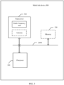
- FIG. 2 is a schematic diagram of a structure of a multi-link device 200 according to an embodiment of this application.
- the multi-link device 200 may correspondingly implement functions or steps implemented by a first multi-link device or a second multi-link device in method embodiments of this application. For example, a multi-link communication link is established or updated, or a traffic identifier-to-link mapping relationship is established or updated. Specific functions or steps are described in detail below.
- the multi-link device 200 may include a transceiver module 210 and a processing module 220.
- the communication apparatus may further include a storage unit.
- the storage unit may be configured to store instructions (code or a program) and/or data.
- the transceiver module 210 and the processing module 220 may be coupled to the storage unit.
- the processing module 220 may read instructions (code or a program) and/or data in the storage unit, to implement a corresponding method.
- the processing module 220 may be implemented by a processor or a processor-related circuit component, and the transceiver module 210 may be implemented by a transceiver, a transceiver-related circuit component, or a communication interface.
- the foregoing units may be disposed independently, or may be partially or completely integrated.
- the transceiver module 210 may be integrated by a sending unit and a receiving unit.
- FIG. 3 is a schematic diagram of a structure of a multi-link device 300 according to an embodiment of this application.
- the multi-link device 300 includes a transceiver 310 and a processor 320.
- the transceiver 310 is configured to communicate with another device by using a transmission medium, so that an apparatus in the multi-link device 300 can communicate with the another device. For example, when the multi-link device 300 is a first multi-link device, the another device is a second multi-link device; or when the multi-link device 300 is a second multi-link device, the another device is a first multi-link device.
- the processor 320 may send and receive data by using the transceiver 310.
- the transceiver 310 may be specifically a radio frequency unit.
- the radio frequency unit may be independent of the multi-link device 300, or may be integrated into the multi-link device 300.
- the transceiver 310 may further include an antenna, for example, a remote antenna independent of the multi-link device 300, or may be an antenna integrated in the multi-link device 300.
- the multi-link device 300 includes at least one processor 320, configured to implement or support the multi-link device 300 in implementing a function of the first multi-link device or the first multi-link device in the methods provided in embodiments of this application.
- an antenna is represented by using a dashed box, which is optional for the multi-link device 300.
- the processor 320 may be a general-purpose processor, a digital signal processor, an application-specific integrated circuit, a field programmable gate array or another programmable logic device, a discrete gate or transistor logic device, or a discrete hardware component, and may implement or execute the methods, steps, and logical block diagrams disclosed in embodiments of this application.
- the general-purpose processor may be a microprocessor or any conventional processor or the like. The steps of the method disclosed with reference to embodiments of this application may be directly performed by a hardware processor, or may be performed by using a combination of hardware in the processor and a software module.
- the multi-link device 300 may further include at least one memory 330, configured to store program instructions and/or data.
- the memory 330 is coupled to the processor 320.
- the coupling in this embodiment of this application may be an indirect coupling or a communication connection between apparatuses, units, or modules in an electrical form, a mechanical form, or another form, and is used for information exchange between the apparatuses, the units, or the modules.
- the processor 320 may cooperate with the memory 330.
- the processor 320 may execute the program instructions and/or the data stored in the memory 330, so that the multi-link device 300 implements a corresponding method.
- At least one of the at least one memory may be located in the processor.
- the memory is represented by using a dashed box, which is optional for the multi-link device 300.
- the memory 330 may be a non-volatile memory, such as a hard disk drive (hard disk drive, HDD) or a solid-state drive (solid-state drive, SSD), or may be a volatile memory (volatile memory), such as a random access memory (random-access memory, RAM).
- the memory is any other medium that can carry or store expected program code in a form of an instruction or a data structure and that can be accessed by a computer, but is not limited thereto.
- the memory in this embodiment of this application may alternatively be a circuit or any other apparatus that can implement a storage function, and is configured to store the program instructions and/or the data.
- connection medium between the transceiver 310, the processor 320, and the memory 330 is not limited in this embodiment of this application.
- the memory 330, the processor 320, and the transceiver 310 are connected by using a bus 340 in FIG. 3 .
- the bus is represented by using a bold line in FIG. 3 .
- the foregoing is merely an example for description.
- a connection manner of other components is not limited thereto.
- the bus may be classified into an address bus, a data bus, a control bus, and the like. For ease of representation, only one thick line is used to represent the bus in FIG. 3 , but this does not indicate that there is only one bus or only one type of bus.
- the multi-link device in this embodiment of this application may further be implemented by using the following components: one or more FPGAs (field programmable gate arrays), a PLD (programmable logic device), a controller, a state machine, gate logic, a discrete hardware component, any other suitable circuit, or any combination of circuits that can perform various functions described in this application.
- FPGAs field programmable gate arrays
- PLD programmable logic device
- controller a state machine
- gate logic gate logic
- discrete hardware component any other suitable circuit, or any combination of circuits that can perform various functions described in this application.
- multi-link devices in the foregoing product forms have any function of the first multi-link device or the second multi-link device in embodiments of this application. Details are not described herein again.
- FIG. 4 is a flowchart of a multi-link communication method according to an embodiment of this application. The method may be applied to the communication system shown in FIG. 1 . The method includes:
- a second multi-link device sends a first request message to a first multi-link device, and the first multi-link device receives the first request message sent by the second multi-link device, where the first request message carries an identifier of one or more links and first indication information of each of the one or more links, and the first indication information indicates an operation type of a corresponding link.
- the first multi-link device may be an AP MLD, and the second multi-link device may be a non-AP MLD; or the second multi-link device may be an AP MLD, and the first multi-link device may be a non-AP MLD; or both the first multi-link device and the second multi-link device are non-AP MLDs.
- the link operation type may include any one or more of the following: (1) establishing multi-link communication; (2) providing only link information or not establishing multi-link communication; (3) adding a link to a multi-link communication link; and (4) deleting a link from the multi-link communication link. It should be understood that the foregoing four operation types are merely examples rather than limitations, and another operation type is also applicable in actual application.
- Providing only link information means that the first request message provides only the link information, and is not used for requesting to establish multi-link communication. In other words, in this specification, not establishing multi-link communication and providing only link information may be interchangeably used.
- Each link has only one operation type, for example, any one of the foregoing four operation types.
- an operation type indicated by the first indication information may be any one of the foregoing four operation types.
- the first request message carries only identifiers of multiple links and first indication information, operation types of any two of the multiple links may be the same or may be different.
- an operation type indicated by the first indication information of the first link and an operation type indicated by the first indication information of the second link may be any one of the following a to f:
- the first request message may further include an identifier and first indication information of another link, such as a third link and a fourth link.
- Operation types corresponding to the third link and the fourth link may be the same as or different from the operation type of the first link or the second link, and details are not described herein again.
- the first request message may further include capability information of a station on each link or other parameter information of each link. This is not limited in this embodiment of this application.
- the first multi-link device After receiving the first request message, the first multi-link device performs, for a link indicated by each identifier carried in the first request message, a corresponding operation on the link based on an operation type indicated by first indication information corresponding to the link.
- no operation may be performed for a link whose operation type is providing only link information or not establishing multi-link communication.
- an operation such as link establishment, link deletion, or link addition may not be performed, but another operation may be performed on the link, for example, saving link information or changing link information. This is not limited herein.
- a first response message may be generated based on a status of each link. Then, S402 is performed.
- the first multi-link device sends the first response message to the second multi-link device, and the second multi-link device receives the first response message sent by the second multi-link device, where the first response message carries the identifiers of the one or more links and second indication information of each link, and the second indication information indicates a status of the link.
- the status of each link is corresponding to an operation type indicated by first indication information corresponding to the link.
- the first link is used as an example, and a status of the first link may be any one of the following:
- each link has only one type of status. If the first response message carries identifiers and second indication information of multiple links, statuses of any two of the multiple links may be the same or different.
- the operation type indicated by the first indication information carried in the first request message may be establishing multi-link communication, providing only link information, or not establishing multi-link communication, and is not adding a link to a multi-link communication link or deleting a link from the multi-link communication link.
- the operation type of the first indication information carried in the first request message may be adding a link to the multi-link communication link or deleting a link from the multi-link communication link.
- the first multi-link device is the AP MLD and the second multi-link device is the non-AP MLD is used.
- multi-link establishment needs to be performed before the non-AP MLD communicates with the AP MLD.
- the non-AP MLD may send an association request frame (the first request message) to the AP MLD.
- the AP MLD After receiving the association request frame, the AP MLD sends an association response frame (the first response message) to the non-AP MLD, to implement multi-link establishment.
- information such as an identifier and first indication information of each link in the association request frame, or information such as an identifier and second indication information of each link in the association response frame may be carried in a multi-link information element (multi-link element, ML element) (where the multi-link information element may also be referred to as a multi-link element).
- multi-link information element multi-link element, ML element
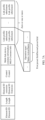
- FIG. 5 is a schematic diagram of a multi-link information element according to an embodiment of this application.
- the multi-link information element includes a control (Control) field, a multi-link device common information (MLD common Info) field, and zero or one or more link profile subelements (Link profile subelement) (or referred to as a link information field).
- Control Control
- MLD common Info multi-link device common information
- Link profile subelement zero or one or more link profile subelements
- the multi-link device common information field carries common information of an MLD on all links, for example, a media access control (Media Access Control, MAC) address (address) of the MLD.
- MAC Media Access Control
- Dedicated information of each link for example, capability information of a station of the MLD on each link, operation type information (namely, first indication information) of the link or status information (namely, second indication information) of the link, and other link-related parameter information is carried in a link profile subelement.
- the non-AP MLD and the AP MLD may exchange information about multiple links by including ML elements in the association request frame and the association response frame, to complete multi-link establishment. Then, communication may be performed on these links.
- the first indication information and/or the second indication information are/is carried in a first preset field in the multi-link information element, and the first preset field is located in a link profile subelement, as shown in FIG. 6 .
- values of the first preset field may each indicate a different meaning.
- the meaning indicated by the value of the first preset field needs to be determined based on a frame type (including the association request frame and the association response frame) in which the first preset field is located and based on the value of the first preset field.
- Table 1 is an example of possible values of the first preset field (namely, an operation type (Action)) in the multi-link information element carried in the association request frame and meanings of the values.
- Table 2 is an example of possible values of the first preset field (namely, a status (Status)) in the multi-link information element carried in the association response frame and meanings of the values.
- Table 1 Association request frame First preset field (First field) Meaning First value Request multi-link establishment Second value Provide only link information or not establish multi-link communication
- the first preset field in the multi-link information element carried in the association request frame is referred to as the first field herein.
- Table 1 lists two possible values of the first field, but this does not mean that the first field needs to include the two values.
- the value of the first field may be only a part of the values in Table 1, or may further include a value other than the values listed in Table 1.
- Table 2 Association response frame First preset field (Second field) Meaning First value Multi-link communication is successfully established. Second value Multi-link communication fails to be established. Third value Only link information is provided or multi-link communication is not established.
- the first preset field in the multi-link information element carried in the association response frame is referred to as the second field herein.
- Table 2 lists three possible values of the second field, but this does not mean that the second field needs to include the three values.
- the value of the second field may be only a part of the values in Table 2, or may further include a value other than the values listed in Table 2.
- a value of the first preset field may indicate a same meaning.
- the meaning indicated by the value of the first preset field may be directly determined based on the value of the first preset field.
- Table 3 is an example of possible values of the first preset field in the multi-link information element carried in the association request frame or the association response frame and meanings of the values.
- Table 3 Association request frame or association response frame First preset field (Third field) Meaning First value An operation type is establishing multi-link communication. Second value A status is that multi-link communication is successfully established. Third value A status is that multi-link communication fails to be established. Fourth value An operation type or a status is that only link information is provided or multi-link communication is not established.
- the first preset fields in the multi-link information elements carried in the association request frame and the association response frame are collectively referred to as the third field herein (the third field is a status when carried in the association response frame, and is an action when carried in the association request frame).
- the fourth value is used in both the association request frame and the association response frame to indicate that only the link information is provided or the multi-link communication is not established.
- different values may be used in the association request frame and the association response frame to indicate that only link information is provided or multi-link communication is not established.
- the fourth value of the first preset field indicates that the operation type is that only the link information is provided or the multi-link communication is not established
- a fifth value of the first preset field indicates that the status is that only the link information is provided or the multi-link communication is not established.
- Table 3 lists four possible values of the third field, but this does not mean that the third field needs to include the four values.
- the value of the third field may be only a part of the values in Table 3, or may further include a value other than the values listed in Table 3.
- the multi-link device may further need to add or delete one or more links in a communication process, which may be implemented by sending a reassociation request frame and response frame.
- the first multi-link device may send a reassociation request frame (the first request message) to the second multi-link device, and after receiving the association request frame, the second multi-link device sends a reassociation response frame (the second response message) to the second multi-link device, to implement link reassociation.
- a reassociation request frame the first request message
- the second multi-link device sends a reassociation response frame (the second response message) to the second multi-link device, to implement link reassociation.
- information such as an identifier and first indication information of each link in the reassociation request frame, or information such as an identifier and second indication information of each link in the reassociation response frame may be carried in a multi-link information element (multi-link element, ML element) (where the multi-link information element may also be referred to as a multi-link element).
- multi-link information element multi-link element, ML element
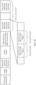
- the first indication information and/or the second indication information are/is carried in a second preset field in the multi-link information element, and the second preset field is located in a link profile subelement.
- the second preset field herein and the foregoing first preset field may be a same field, as shown in FIG. 7A , or may be different fields, as shown in FIG. 7B . This is not limited in this embodiment of this application.
- the following uses an example in which the second preset field and the first preset field are the same field.
- values of the first preset field may each indicate a different meaning.
- the meaning indicated by the value of the first preset field needs to be determined based on a frame type (including the reassociation request frame and the reassociation response frame) in which the first preset field is located and based on the value of the first preset field.
- Table 4 is an example of possible values of the first preset field (operation type (Action)) in the multi-link information element carried in the reassociation request frame and meanings of the values.
- Table 5 is an example of possible values of the first preset field (status (Status)) in the multi-link information element carried in the reassociation response frame and meanings of the values.
- Table 4 Reassociation request frame First preset field (Fourth field) Meaning First value Request to add a link Second value Request to delete a link Third value Provide only link information
- the first preset field in the multi-link information element carried in the reassociation request frame is referred to as the fourth field herein.
- Table 4 lists three possible values of the fourth field, but this does not mean that the fourth field needs to include the three values.
- the value of the fourth field may be only a part of the values in Table 4, or may further include a value other than the values listed in Table 4.
- the link profile subelement may include only an identifier of the link and an operation type of the link, or the link profile subelement may not carry information other than the identifier of the link and the operation type, for example, does not need to carry capability information of a station working on the link, to reduce resources.
- Table 5 Reassociation response frame Fifth field Meaning First value A link is successfully added. Second value A link fails to be added. Third value A link is successfully deleted. Fourth value A link fails to be deleted. Fifth value Only link information is provided.
- the first preset field in the multi-link information element carried in the reassociation response frame is referred to as the fifth field herein.
- Table 5 lists five possible values of the fifth field, but this does not mean that the fifth field needs to include the five values.
- the value of the fifth field may be only a part of the values in Table 5, or may further include a value other than the values listed in Table 5.
- a value of the first preset field may indicate a same meaning.
- the meaning indicated by the value of the first preset field may be directly determined based on the value of the first preset field.
- Table 6 is an example of possible values of the first preset field in the multi-link information element carried in the reassociation request frame or the reassociation response frame and meanings of the values.
- Table 6 Reassociation request frame or reassociation response frame First preset field (Sixth field) Meaning First value An operation type is requesting to add a link. Second value An operation type is requesting to delete a link. Third value A status is that a link is successfully added. Fourth value A status is that a link fails to be added. Fifth value A status is that a link is successfully deleted. Sixth value A status is that a link fails to be deleted. Seventh value Only link information is provided.
- the first preset field in the multi-link information element carried in the reassociation request frame or the reassociation response frame are collectively referred to as the sixth field herein.
- the seventh value is used in both the reassociation request frame and the reassociation response frame to indicate that only link information is provided.
- different values may be used in the reassociation request frame and the reassociation response frame to indicate that only link information is provided or multi-link communication is not established.
- the seventh value of the first preset field indicates that the operation type is that only the link information is provided or the multi-link communication is not established
- an eighth value of the first preset field indicates that the status is that only the link information is provided or the multi-link communication is not established.
- Table 6 lists seven possible values of the sixth field, but this does not mean that the sixth field needs to include the seven values.
- the value of the sixth field may be only a part of the values in Table 6, or may further include a value other than the values listed in Table 6.
- the first field, the second field, the fourth field, and the fifth field may be combined into one field, for example, a seventh field.
- a value of the first preset field may indicate a same meaning.
- Table 7 is an example of possible values of the first preset field in the multi-link information element carried in the association request frame, the association response frame, the reassociation request frame, or the reassociation response frame, and meanings of the values.
- Table 7 Association request frame, association response frame, reassociation request frame, or reassociation response frame First preset field (Seventh field) Meaning First value Multi-link establishment is requested. Second value Multi-link communication is successfully established. Third value Multi-link communication fails to be established. Fourth value Only link information is provided. Fifth value A link is requested to be added. Sixth value A link is requested to be deleted. Seventh value A link is successfully added. Eighth value A link fails to be added. Ninth value A link is successfully deleted.
- the first preset field in the multi-link information element carried in the association request frame, the association response frame, the reassociation request frame, or the reassociation response frame is collectively referred to as the seventh field herein.
- the fourth value is used in both the request frame and the response frame to indicate that only the link information is provided.
- different values may be used in the request frame and the response frame to indicate that only link information is provided.
- the fourth value of the first preset field indicates that the operation type is that only the link information is provided or the multi-link communication is not established, and a tenth value of the first preset field indicates that the status is that only the link information is provided.
- Table 7 lists nine possible values of the seventh field, but this does not mean that the seventh field needs to include the nine values.
- the value of the seventh field may be only a part of the values in Table 7, or may further include a value other than the values listed in Table 7.
- the AP MLD may carry information about the new link in a multi-link information element, for example, in a new link profile subelement.
- an MLD common information field in the multi-link information element may carry third indication information, indicating that the multi-link element carries information about a new link.
- N is a positive integer
- the AP MLD when the AP MLD starts (or uses or enables) a new link, information about the new link may be carried in each beacon frame of N consecutive beacon frames, where N is a positive integer, to ensure that the information about the new link can be effectively received by the non-AP MLD.
- N is set and broadcast by an AP, or is specified in a standard. This is not limited in this embodiment of this application.
- the value of N may be any value in a range [1, 10], for example, 2, 3, 4, or 5.
- the first indication information is carried in the first request message (the association request frame or the reassociation request frame), and the second indication information is carried in the first response message (the association response frame or the reassociation response frame).
- an MLD establishes multi-link communication on a part of or all links supported by the MLD, and may further add a link to or delete a link from an established multi-link communication link based on a communication requirement in subsequent communication.
- a new link may be started. This improves flexibility of multi-link communication performed by the MLD from multiple aspects, and can well meet a requirement of dynamically updating the communication link by the MLD.
- a traffic-to-link mapping solution is further provided, to provide different services for different traffic. For example, unimportant traffic is mapped to a part of links, and important traffic is mapped to all links. Alternatively, different traffic is mapped to corresponding links based on rate and latency characteristics of different links.
- FIG. 9 is a flowchart of a traffic-to-link mapping method according to an embodiment of this application. The method may be applied to the communication system shown in FIG. 1 . The method includes:
- a second multi-link device sends a second message to a first multi-link device, and the first multi-link device receives the second message from the second multi-link device, where the second message carries traffic identifier-to-link mapping information.
- the second multi-link device may send the second message to the first multi-link device in a broadcast mode (in other words, the second message is a broadcast message), or may send the second message to the first multi-link device in a multicast mode (in other words, the second message is a multicast message), or may send the second message to the first multi-link device in a unicast mode (in other words, the second message is a unicast message).
- a broadcast mode in other words, the second message is a broadcast message
- the second message is a multicast mode
- the second message is a unicast message
- the first multi-link device may be an AP MLD, and the second multi-link device may be a non-AP MLD; or the second multi-link device may be an AP MLD, and the first multi-link device may be a non-AP MLD; or both the first multi-link device and the second multi-link device are non-AP MLDs.
- the second link may send the second message to the first multi-link device in the broadcast or multicast mode
- the second multi-link device may be an AP MLD
- the first multi-link device may be a non-AP MLD.
- the second multi-link device before the second multi-link device sends the second message to the first multi-link device, the second multi-link device further receives a third message from the first multi-link device, where the third message is used for requesting to establish or update a traffic identifier-to-link mapping relationship.
- the second message is a response message for the third message.
- the second message may further carry fourth indication information, and the fourth indication information indicates a second mode used for negotiating a traffic identifier-to-link mapping.
- the first multi-link device Before the first multi-link device receives second message from a second multi-link device, the first multi-link device further sends a third message to the second multi-link device, where the third message carries fifth indication information, and the fifth indication information indicates a first mode used for negotiating a traffic identifier-to-link mapping.
- the first mode may be: a traffic-to-link mapping is requested to be established, but a specific traffic-to-link mapping method of a requester (namely, the first multi-link device) is not carried; a traffic-to-link mapping is requested to be established, a suggested mapping method is carried, and a responder (namely, the second multi-link device) is allowed to modify a mapping relationship in a response frame; or a traffic-to-link mapping is requested to be established, a demanded mapping method is carried, and a responder is not allowed to modify a mapping relationship in a response frame.
- the second mode may be: the traffic-to-link mapping is successfully established, and a final mapping method is carried; the traffic-to-link mapping is not successfully established, and the suggested mapping method is carried; the traffic-to-link mapping is not successfully established, the demanded mapping method is carried, and if a requester sends a request again, the mapping can be successfully established only by using the mapping method; or the traffic-to-link mapping fails to be established.
- the second message may further carry sixth indication information, indicating that the second message carries broadcast traffic-to-link mapping information.
- the first multi-link device may further send a fourth message to the second multi-link device, where the fourth message carries seventh indication information, and the seventh indication information indicates that the first multi-link device supports broadcast traffic-to-link mapping information.
- the second message further carries eighth indication information, indicating an accumulative quantity of updates of traffic-to-link mapping information, so that after receiving the second message, a multi-link device that wakes up after sleep learns an update status of the traffic-to-link mapping information, and determines whether the multi-link device needs to update the traffic-to-link mapping relationship.
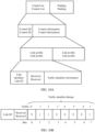
- the traffic-to-link mapping information may be carried in a header (Header) field of MAC.
- a new control type is defined by using an A-control subfield (A-Control subfield) in the MAC header, to carry traffic identifier-to-link mapping information.
- A-Control subfield A-control subfield
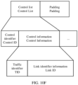
- FIG. 10A is a schematic diagram of a possible MAC header according to an embodiment of this application.
- the MAC header carries a control (control) ID and control information (control information) corresponding to the control ID.
- the control information field includes two link profile (link profile) fields.
- Each link profile includes one piece of link identifier information (link ID) and identifier information of traffic mapped to the link.
- the identifier information of the traffic may be a traffic identifier (Traffic ID, TID) bitmap (bitmap), or may be a starting traffic identifier (starting TID) and an ending traffic identifier (ending TID). A TID that falls between the starting TID and the ending TID is mapped to the link. Alternatively, the identifier information is in another form. This is not limited in this embodiment of this application.
- Each bit in the traffic identifier bitmap corresponds to one traffic identifier, different bits correspond to different traffic identifiers, and each traffic identifier represents a specific type of traffic.
- a bit i corresponds to a traffic identifier i
- a value of i starts from 0, and a maximum value is a quantity of bits in the traffic identifier bitmap minus 1.
- the quantity of bits in the traffic identifier bitmap may be 4, 8, 12, 16, or the like.
- a specific quantity of bits may be determined based on a quantity of bits configured in the control information. This is not limited in this application.
- FIG. 10B is a schematic diagram of a possible traffic identifier bitmap according to an embodiment of this application.
- the traffic identifier bitmap includes 8 bits.
- a first bit (bit 0) corresponds to traffic whose TID is 0, a second bit (bit 1) corresponds to traffic whose TID is 1, a third bit (bit 2) corresponds to traffic whose TID is 3, a fourth bit (bit 3) corresponds to traffic whose TID is 4, a fifth bit (bit 4) corresponds to traffic whose TID is 4, a sixth bit (bit 5) corresponds to traffic whose TID is 5, a seventh bit (bit 6) corresponds to traffic whose TID is 6, and an eighth bit (bit 7) corresponds to traffic whose TID is 7.
- Traffic whose corresponding field value is 1 is mapped to a link, or traffic whose corresponding field value is 0 is mapped to the link.
- the traffic whose corresponding field value is 1 is mapped to the link.
- the traffic identifier bitmap shown in FIG. 10B indicates that traffic 1, traffic 2, and traffic 7 are mapped to a link corresponding to the link profile field.
- a special link ID may be carried in another link profile to indicate that information in the current link profile is invalid information.
- FIG. 10C is a schematic diagram of another possible MAC header according to an embodiment of this application.
- a control information (control information) field corresponding to each control (control) ID includes a link profile (link profile) field.
- Each link profile includes one piece of link identifier information (link ID) and identifier information of traffic mapped to the link.
- the second multi-link device may include a link profile of one or more links in the MAC header based on an actual traffic-to-link mapping requirement.
- identifier information of traffic in the link profile in Example 2 may be a traffic identifier bitmap, a starting traffic identifier and an ending traffic identifier, or in another form. This is not limited in this embodiment of this application.
- the identifier information of the traffic is the traffic identifier bitmap, refer to FIG. 10B . Details are not described herein again.
- FIG. 10D is a schematic diagram of another possible MAC header according to an embodiment of this application.
- the MAC header carries a traffic identifier (TID) ID and control information (control information) corresponding to the TID ID.
- the control information field includes two traffic profile (TID profile) fields.
- Each TID profile includes one piece of traffic identifier information (TID ID) identifier information of a link to which the traffic is mapped.
- the identifier information of the link may be a link identifier bitmap (link ID bitmap), or may be a starting link identifier (starting link ID) and an ending link identifier (ending link ID).
- the traffic is mapped to a link corresponding to a link ID that falls between the starting link ID and the ending link ID.
- the identifier information of the link may be in another form. This is not limited in this embodiment of this application.
- Each bit in the link identifier bitmap corresponds to one link identifier, and different bits correspond to different link identifiers.
- a bit i corresponds to a link identifier i
- a value of i starts from 0, and a maximum value is a quantity of bits in the link identifier bitmap minus 1.
- the quantity of bits in the link identifier bitmap may be 4, 8, 12, 16, or the like.
- a specific quantity of bits may be determined based on a quantity of bits configured in the control information. This is not limited in this application.
- FIG. 10E is a schematic diagram of a possible link identifier bitmap according to an embodiment of this application.
- the link identifier bitmap includes 8 bits.
- a first bit (bit 0) corresponds to a link whose link ID is 0,
- a second bit (bit 1) corresponds to a link whose link ID is 1
- a third bit (bit 2) corresponds to a link whose link ID is 3
- a fourth bit (bit 3) corresponds to a link whose link ID is 4
- a fifth bit (bit 4) corresponds to a link whose link ID is 4
- a sixth bit (bit 5) corresponds to a link whose link ID is 5
- the traffic is mapped to a link whose corresponding field value is 1, or the traffic is mapped to a link whose corresponding field value is 0.
- the traffic is mapped to the link whose corresponding field value is 1.
- the link identifier bitmap shown in FIG. 10E indicates that the traffic is mapped to links 1, 2, and 7.
- a special TID ID may be carried in another TID profile to indicate that information in the TID profile is invalid information.
- the quantity of bits in the link identifier bitmap may alternatively be another value, for example, 4, 12, or 16, and may be specifically determined based on a quantity of bits configured in the control information.
- FIG. 10F is a schematic diagram of another possible MAC header according to an embodiment of this application.
- a control information (control information) field corresponding to each control (control) ID includes a traffic profile (TID profile) field.
- Each TID profile includes one piece of traffic identifier information (TID) information about a link to which the traffic is mapped.
- the second multi-link device may include a TID profile of one or more pieces of traffic in the MAC header based on an actual traffic-to-link mapping requirement.
- identifier information of a link in the TID profile in Example 4 may be a link identifier bitmap, a starting link identifier and an ending link identifier, or in another form. This is not limited in this embodiment of this application.
- the identifier information of the link is the link identifier bitmap, refer to FIG. 10E . Details are not described herein again.
- the traffic identifier-to-link mapping information is carried in an information element indicating the traffic identifier-to-link mapping relationship.
- a name of the information element indicating the traffic identifier-to-link mapping relationship is not limited.
- the name may be a traffic identifier-to-link mapping information element (TID-to-Link Mapping element) (or referred to as a traffic identifier-to-link mapping element).
- TID-to-Link Mapping element traffic identifier-to-link mapping information element
- the following uses the traffic identifier-to-link mapping information element as an example.
- FIG. 11A is a schematic diagram of a traffic identifier-to-link mapping information element according to an embodiment of this application.
- the traffic identifier-to-link mapping information element includes a control (Control) field and a traffic identifier-to-link mapping information (TID-to-Link Mapping info) field.
- the TID-to-Link Mapping info field carries traffic identifier-to-link mapping information. It should be understood that the traffic identifier-to-link mapping information (TID-to-Link Mapping info) field may alternatively have another name. This is not limited in this embodiment of this application.
- the traffic identifier-to-link mapping information element may further include fields such as an element identifier (Element ID) field, a length (Length) field, or an element ID extension (Element ID Extension) field, which is not limited herein.
- the traffic identifier-to-link mapping information field includes one or more link profile (Link profile) fields, and each link profile field includes identifier information of one link and identifier information of one or more pieces of traffic mapped to the link.
- the identifier information of the traffic may be a traffic identifier bitmap (TID bitmap), or may be a starting traffic identifier (starting TID) and an ending traffic identifier (ending TID). A TID that falls between the starting TID and the ending TID is mapped to the link.
- the identifier information may be in another form. This is not limited in this embodiment of this application.
- FIG. 11B an example in which the identifier information of the traffic is a traffic identifier bitmap is used as an example. For a specific implementation of the traffic identifier bitmap, refer to FIG. 10B . Details are not described herein again.
- the TID bitmap in the link profile field when the TID bitmap in the link profile field is all 0s, it may indicate that the link is disabled.
- a link profile field may further include a field indicating whether to disable a corresponding link, for example, a disable (Disable) field (or another name, which is not limited in this application). Further, if the disable field indicates that the link is disabled, the link profile field may not carry identifier information of traffic mapped to the link (in FIG. 11C , a traffic identifier bitmap is used as an example), or the link profile field carries only a link identifier and the disable field, or the TID bitmap is all 0s.
- a disable (Disable) field or another name, which is not limited in this application.
- a traffic identifier-to-link mapping information field includes one or more traffic profile fields, and each traffic profile field includes identifier information of one traffic and identifier information of one or more links to which the traffic is mapped.
- the identifier information of the link may be a link identifier bitmap (link ID bitmap), or may be a starting link identifier (starting link ID) and an ending link identifier (ending link ID).
- the traffic is mapped to a link corresponding to a link ID that falls between the starting link ID and the ending link ID.
- the identifier information of the link may be a link identifier list (link ID list).
- the identifier information of the link may be in another form.
- FIG. 11D an example in which the identifier information of the link is the link identifier bitmap is used.
- the link identifier bitmap For a specific implementation of the link identifier bitmap, refer to FIG. 10E . Details are not described herein again.
- the traffic profile field may alternatively exist in a form of an information element.
- the traffic profile field may further include fields such as an element identifier (element ID) field, a length (Length) field, and an element ID extension field (element ID Extension field), as shown in FIG. 11E .
- control field may be different based on a manner of delivering the second message (or a type of the second message).
- the broadcast and unicast modes are described in the following.
- a request frame (the third message) and a response frame (the second message) may each carry a traffic identifier-to-link mapping information element.
- FIG. 12 is a schematic diagram of another possible traffic identifier-to-link mapping information element according to an embodiment of this application.
- a control field includes a mapping request (TID-to-Link Mapping request) field, indicating a type of a frame in which a traffic identifier-to-link mapping information element is located.
- a length of the field may be 1 bit, where 1 indicates a request, and 0 indicates a response.
- the control field may further include a third preset field, for example, a negotiation type field (or a negotiation mode field, or another name, which is not limited herein), indicating a mode used for negotiating a traffic identifier-to-link mapping.
- a negotiation type field in the traffic identifier-to-link mapping information element carried in the request frame indicates a mode (namely, the first mode described above) used by a requester to negotiate the traffic identifier-to-link mapping.
- a negotiation type field in the traffic identifier-to-link mapping information element carried in the response frame indicates a mode (namely, the second mode described above) used by a responder to negotiate the traffic identifier-to-link mapping.
- values of the negotiation type fields may indicate different meanings.
- the meaning indicated by the value of the negotiation type field needs to be determined based on a frame type (including the request frame and the response frame) in which the negotiation type field is located and a value of the negotiation type field.
- Table 8 is an example of possible values of the negotiation type field in the traffic identifier-to-link mapping information element carried in the request frame and meanings of the values.
- Table 9 is an example of values of the negotiation type field in the traffic identifier-to-link mapping information element carried in the response frame and meanings of the values.
- Table 8 lists three possible values of the negotiation type field in the request frame, but it does not mean that the negotiation type field needs to include the three values.
- the value of the negotiation type field may be only a part of the values in Table 8, or may further include a value other than the values listed in Table 8.
- Table 9 Response frame Negotiation type field Meaning First value A traffic identifier-to-link mapping is successfully established, and a final mapping method is carried (in a link profile). Second value A traffic-to-link mapping is not successfully established, and a suggested mapping method is carried (in a link profile).
- Third value A traffic-to-link mapping is not successfully established, a demanded mapping method is carried (in a link profile), and if a requester sends a request again, the mapping can be successfully established only by using the mapping.
- Fourth value A traffic identifier-to-link mapping fails to be established.
- Table 9 lists four possible values of the negotiation type field in the response frame, but it does not mean that the negotiation type field needs to include the four values.
- the value of the negotiation type field may be only a part of the values in Table 9, or may further include a value other than the values listed in Table 9.
- values of the negotiation type fields may indicate a same meaning.
- the meaning indicated by the value of the negotiation type field may be directly determined based on the value of the negotiation type field.
- Table 10 is an example of possible values of the negotiation type field in the traffic identifier-to-link mapping information element carried in the request frame or the response frame and meanings of the values.
- Third value demand (sent by the requester) A traffic identifier-to-link mapping is requested to be established, a mapping method demanded by the requester is carried (in a link profile), and a responder is not allowed to modify a mapping relationship in a response frame.
- Fourth value accept (sent by a responder) A traffic identifier-to-link mapping is successfully established, and a final mapping method is carried (in a link profile).
- Fifth value alternate (sent by the responder) A traffic-to-link mapping is not successfully established, and a suggested mapping method is carried (in a link profile).
- Table 10 lists seven possible values of the negotiation type fields in the request frame and the response frame, but it does not mean that the negotiation type field needs to include the seven values.
- the value of the negotiation type field may be only a part of the values in Table 10, or may further include a value other than the values listed in Table 10.
- the control field may further include ninth indication information, for example, a traffic direction (Direction) field (or another name, which is not limited herein), indicating a direction of traffic mapped to a link.
- a direction type may include downlink and uplink, and may further include both uplink and downlink (both UL and DL).
- a field length may be 1 bit or 2 bits. For example, a value of 0 of the field indicates uplink, a value of 1 indicates downlink, and a value of 3 indicates uplink and downlink.
- the control field may further include a second preset field, for example, a default mode field (or another name, which is not limited herein), and a length may be 1 bit.
- a default mode field is set to a preset value (for example, 1), it indicates that a default mapping manner is used.
- all TIDs (or each TID) may be mapped to each link on which multi-link communication is established.
- the traffic identifier-to-link mapping information element may not carry traffic identifier-to-link mapping information, or the traffic identifier-to-link mapping information element carries only another field such as a control field, an element identifier, a length, or an element ID extension.
- FIG. 13 is a schematic diagram of a traffic identifier-to-link mapping information element obtained in one of the combination manners.
- the following describes a method for using any one of the traffic identifier-to-link mapping information elements shown in FIG. 11A to FIG. 13 .
- an association request frame (a third message) and an association response frame (a second message) carry a traffic identifier-to-link mapping information element, so that negotiation of a traffic identifier-to-link mapping is completed during multi-link establishment.
- an extremely high throughput (Extremely High Throughput, EHT) action frame (Action frame) may be defined, and the EHT action frame carries a traffic identifier-to-link mapping information element, to update the mapping relationship.
- FIG. 14 is a flowchart of a method for updating a traffic identifier-to-link mapping relationship according to an embodiment of this application. The method may be applied to the communication system shown in FIG. 1 .
- a first multi-link device sends a request frame (a third message) to a second multi-link device, where the request frame carries a first traffic identifier-to-link mapping information element, and is used for requesting to update a traffic identifier-to-link mapping relationship.
- the second multi-link device sends a response frame (second message) to the first multi-link device, where the response frame carries a second traffic identifier-to-link mapping information element, and is used for responding to the update of the traffic identifier-to-link mapping relationship.
- FIG. 15 is a schematic diagram of a possible frame structure of an EHT action frame according to an embodiment of this application.
- a value of a category (Category) field may be "EHT", indicating an action frame in 802.11be.
- a value of a TID-to-link mapping request field in the traffic identifier-to-link mapping information element in the request frame may be set to 1, and a value of a TID-to-link mapping request field in the traffic identifier-to-link mapping information element in the response frame may be set to 0.
- a value of an EHT action (EHT Action) field in the EHT action frame may be "TID-to-link mapping update information (TID-to-Link mapping update information)", indicating that the EHT action frame is used for updating the traffic identifier-to-link mapping relationship.
- a value of an EHT action field in the request frame may be "a traffic identifier-to-link mapping request (TID-to-Link mapping update request)", and a value of an EHT action field in the response frame may be "a traffic identifier-to-link mapping request response (TID-to-Link mapping update response)".
- Table 10 is used as an example.
- a value of a negotiation type field in the traffic identifier-to-link mapping information element in the response frame is a fourth value (accept)
- negotiation of the traffic identifier-to-link mapping relationship is completed. Otherwise, the first multi-link device may continue to send a request frame until a value of a negotiation type field in a received response frame is the fourth value (accept).
- the second multi-link device may be an AP MLD
- the first multi-link device may be a non-AP MLD.
- the second multi-link device may include a traffic identifier-to-link mapping information element in a beacon frame, used for broadcasting traffic identifier-to-link mapping information to a station.
- FIG. 16 is a schematic diagram of another traffic identifier-to-link mapping information element according to an embodiment of this application.
- the traffic identifier-to-link mapping information element may be carried in a beacon frame.
- a control field of the traffic identifier-to-link mapping information element includes a broadcast (Broadcast) field (sixth indication information), indicating that the current traffic identifier-to-link mapping information element carries broadcast traffic-to-link mapping information.
- the traffic-to-link mapping information may be sent to multiple stations, and is used by the multiple stations to perform traffic-to-link mapping.
- control field may further include a traffic direction (Direction) field, indicating a direction of traffic mapped to a link.
- a direction type may include downlink and uplink, and may further include both uplink and downlink (both UL and DL).
- a field length can be 1 bit or 2 bits. 0 indicates uplink, 1 indicates downlink, and 3 indicates uplink and downlink.
- the control field may further include a default mode field, and a length may be 1 bit.
- a default mode field is set to a preset value (for example, 1), it indicates that a default mapping manner is used.
- all TIDs (or each TID) may be mapped to each link on which multi-link communication is established.
- the traffic identifier-to-link mapping information element may not carry traffic identifier-to-link mapping information, or the traffic identifier-to-link mapping information element carries only another field such as a control field, an element identifier, a length, or an element ID extension.
- a station multi-link device such as the first multi-link device may send seventh indication information to the second multi-link device, to indicate that a device type of the first multi-link device is a broadcast traffic identifier-to-link mapping supported device (broadcast TID-to-Link mapping supported MLD). Further, when the second multi-link device broadcasts the beacon frame, the first multi-link device receives a traffic identifier-to-link mapping information element in the beacon frame, and updates the traffic identifier-to-link mapping relationship thereof based on the traffic identifier-to-link mapping information element.
- the non-AP MLD cannot send a traffic identifier-to-link mapping information element to the AP MLD to change the traffic identifier-to-link mapping relationship thereof.
- the non-AP MLD claims to be broadcast TID-to-link mapping supported.
- seventh indication information may be carried in an association request frame, indicating that the non-AP MLD is broadcast TID-to-link mapping supported.
- the seventh indication information may be specifically carried in an EHT capabilities element (capabilities element).
- the AP MLD may reply with an association response frame, and the association response frame carries a traffic identifier-to-link mapping information element, used for assigning an initial value of a traffic identifier-to-link mapping relationship.
- the AP MLD may include a traffic identifier-to-link mapping information element in the beacon frame, used for broadcasting the current traffic identifier-to-link mapping information to the station. After receiving by the non-AP MLD, the non-AP needs to update the mapping relationship.
- the AP MLD needs to use this event as a critical update (critical update), and add one to a value of a check beacon field (check Beacon field) (namely, eighth indication information) in a next to-be-sent traffic indication bitmap (Traffic Indication Map, TIM) frame.
- critical update critical update
- check Beacon field namely, eighth indication information
- the non-AP MLD may compare a value of the received check beacon frame field with the value of the check beacon frame field before sleep, to learn whether the AP MLD updates the mapping relationship, and when determining that the AP MLD updates the mapping relationship, update the mapping relationship based on content of a latest traffic identifier-to-link mapping information element.
- the AP MLD may carry a counter field (namely, eighth indication information) in the beacon frame, for example, referred to as a traffic identifier-to-link mapping update counter (TID-to-Link mapping update counter).
- a value of the counter is initialized to 0.
- the count value of the counter is increased by 1.
- a quantity of bits of the counter may be set and broadcast by an AP, or specified in a standard. This is not limited in this embodiment of this application. For example, it is assumed that the counter is represented by 8 bits, and a maximum value of the counter is 255. When the count value of the counter is greater than 255, a modulo operation (mod) is performed on 256, so that 255 plus 1 becomes 0.
- the non-AP MLD may compare a value of a received counter frame field with the value of the counter frame field before sleep, to learn whether the AP MLD updates the mapping relationship, and when determining that the AP MLD updates the mapping relationship, update the mapping relationship based on content of a latest traffic identifier-to-link mapping information element.
- the counter may be carried in the traffic identifier-to-link mapping information element in the beacon frame.
- the first multi-link device establishes or updates the traffic-to-link mapping relationship based on the mapping information.
- the first multi-link device establishes the identifier-to-link mapping relationship based on the identifier-to-link mapping information carried in the association response frame.
- the first multi-link device updates the identifier-to-link mapping relationship based on the identifier-to-link mapping information carried in the EHT action frame.
- the first multi-link device updates the identifier-to-link mapping relationship based on the identifier-to-link mapping information carried in the beacon frame.
- the second multi-link device adds the traffic-to-link mapping information to the second message, so that the multi-link device can further establish a traffic-to-link mapping relationship during multi-link establishment, or update the traffic-to-link mapping relationship after completing multi-link establishment, to manage traffic more flexibly and improve quality of service.
- system and “network” may be used interchangeably in embodiments of this application.
- At least one means one or more, and “multiple” means two or more.
- the term “and/or” describes an association relationship for describing associated objects and represents that three relationships may exist.
- a and/or B may represent the following three cases: Only A exists, both A and B exist, and only B exists.
- a and B each may be singular or plural.
- the character “/” generally indicates an “or” relationship between the associated objects.
- "At least one of the following items (pieces)” or a similar expression thereof refers to any combination of these items, including any combination of singular items (pieces) or plural items (pieces).
- at least one of a, b, or c may indicate a, b, c, a and b, a and c, b and c, or a, b, and c.
- ordinal numbers such as “first” and “second” in embodiments of this application are used to distinguish between multiple objects, but are not intended to limit an order, a time sequence, priorities, or importance of the multiple objects.
- a first priority criterion and a second priority criterion are merely used to distinguish between different criteria, but do not indicate different content, priorities, importance, or the like of the two criteria.
- Embodiments of this application are described with reference to the flowcharts and/or block diagrams of the method, the device (system), and the computer program product according to embodiments of this application. It should be understood that computer program instructions may be used to implement each process and/or each block in the flowcharts and/or the block diagrams and a combination of a process and/or a block in the flowcharts and/or the block diagrams.
- These computer program instructions may be provided for a general-purpose computer, a dedicated computer, an embedded processor, or a processor of any other programmable data processing device to generate a machine, so that the instructions executed by a computer or a processor of any other programmable data processing device generate an apparatus for implementing a specific function in one or more processes in the flowcharts and/or in one or more blocks in the block diagrams.
- All or some of the foregoing embodiments may be implemented by using software, hardware, firmware, or any combination thereof.
- software is used to implement embodiments, all or a part of embodiments may be implemented in a form of a computer program product.
- the computer program product includes one or more computer instructions.
- the computer may be a general-purpose computer, a dedicated computer, a computer network, or other programmable apparatuses.
- the computer instructions may be stored in a computer-readable storage medium or may be transmitted from one computer-readable storage medium to another readable storage medium.
- the computer instructions may be transmitted from a website, computer, server, or data center to another website, computer, server, or data center in a wired (for example, a coaxial cable, an optical fiber, or a digital subscriber line (digital subscriber line, DSL)) or wireless (for example, infrared, radio, or microwave) manner.
- the computer-readable storage medium may be any usable medium accessible by the computer, or a data storage device, for example, a server or a data center, integrating one or more usable media.
- the usable medium may be a magnetic medium (for example, a floppy disk, a hard disk, or a magnetic tape), an optical medium (for example, a digital versatile disc (digital versatile disc, DVD)), a semiconductor medium (for example, a solid state disk (solid state disk, SSD)), or the like.
- a magnetic medium for example, a floppy disk, a hard disk, or a magnetic tape
- an optical medium for example, a digital versatile disc (digital versatile disc, DVD)
- a semiconductor medium for example, a solid state disk (solid state disk, SSD)
Landscapes
- Engineering & Computer Science (AREA)
- Computer Networks & Wireless Communication (AREA)
- Signal Processing (AREA)
- Mobile Radio Communication Systems (AREA)
- Data Exchanges In Wide-Area Networks (AREA)
Priority Applications (1)
| Application Number | Priority Date | Filing Date | Title |
|---|---|---|---|
| EP25184748.9A EP4648547A3 (de) | 2020-08-21 | 2021-06-28 | Multilink-kommunikationsverfahren, verfahren zur abbildung von verkehr zu verbindung und vorrichtung |
Applications Claiming Priority (2)
| Application Number | Priority Date | Filing Date | Title |
|---|---|---|---|
| CN202010852529.1A CN114079949B (zh) | 2020-08-21 | 2020-08-21 | 一种多链路通信方法、业务与链路映射的方法及设备 |
| PCT/CN2021/102657 WO2022037254A1 (zh) | 2020-08-21 | 2021-06-28 | 一种多链路通信方法、业务与链路映射的方法及设备 |
Related Child Applications (2)
| Application Number | Title | Priority Date | Filing Date |
|---|---|---|---|
| EP25184748.9A Division-Into EP4648547A3 (de) | 2020-08-21 | 2021-06-28 | Multilink-kommunikationsverfahren, verfahren zur abbildung von verkehr zu verbindung und vorrichtung |
| EP25184748.9A Division EP4648547A3 (de) | 2020-08-21 | 2021-06-28 | Multilink-kommunikationsverfahren, verfahren zur abbildung von verkehr zu verbindung und vorrichtung |
Publications (3)
| Publication Number | Publication Date |
|---|---|
| EP4192080A1 true EP4192080A1 (de) | 2023-06-07 |
| EP4192080A4 EP4192080A4 (de) | 2024-01-24 |
| EP4192080B1 EP4192080B1 (de) | 2025-12-31 |
Family
ID=80282580
Family Applications (2)
| Application Number | Title | Priority Date | Filing Date |
|---|---|---|---|
| EP25184748.9A Pending EP4648547A3 (de) | 2020-08-21 | 2021-06-28 | Multilink-kommunikationsverfahren, verfahren zur abbildung von verkehr zu verbindung und vorrichtung |
| EP21857350.9A Active EP4192080B1 (de) | 2020-08-21 | 2021-06-28 | Multilink-kommunikationsverfahren, dienst- und link-mapping-verfahren und vorrichtung |
Family Applications Before (1)
| Application Number | Title | Priority Date | Filing Date |
|---|---|---|---|
| EP25184748.9A Pending EP4648547A3 (de) | 2020-08-21 | 2021-06-28 | Multilink-kommunikationsverfahren, verfahren zur abbildung von verkehr zu verbindung und vorrichtung |
Country Status (13)
| Country | Link |
|---|---|
| US (1) | US20230209536A1 (de) |
| EP (2) | EP4648547A3 (de) |
| JP (2) | JP7613800B2 (de) |
| KR (1) | KR20230051685A (de) |
| CN (4) | CN114079949B (de) |
| AU (2) | AU2021327577B2 (de) |
| CA (1) | CA3190377A1 (de) |
| ES (1) | ES3064851T3 (de) |
| FI (1) | FI4192080T3 (de) |
| MX (1) | MX2023002130A (de) |
| PL (1) | PL4192080T3 (de) |
| PT (1) | PT4192080T (de) |
| WO (1) | WO2022037254A1 (de) |
Families Citing this family (21)
| Publication number | Priority date | Publication date | Assignee | Title |
|---|---|---|---|---|
| US12120760B2 (en) * | 2020-10-23 | 2024-10-15 | Nxp Usa, Inc. | Multi-link device (MLD) setup and multi-link operation (MLO) |
| EP4207858B1 (de) | 2020-12-18 | 2024-09-04 | Guangdong Oppo Mobile Telecommunications Corp., Ltd. | Multi-link-kommunikation und aushandlung von tid-zu-verbindung mapping |
| US20250080628A1 (en) * | 2021-03-29 | 2025-03-06 | Lg Electronics Inc. | Method and apparatus for defining entire profile sub-field in ml element for ml reconfiguration in wireless lan system |
| CN116671142A (zh) * | 2021-04-22 | 2023-08-29 | Oppo广东移动通信有限公司 | 业务标识到链路映射的方法和多链路设备 |
| EP4362542A4 (de) * | 2021-06-22 | 2025-05-21 | LG Electronics Inc. | Verfahren und vorrichtung zur durchführung von tid-zu-link-zuordnung in einem wlan-system |
| US20240298371A1 (en) * | 2021-07-19 | 2024-09-05 | Beijing Xiaomi Mobile Software Co., Ltd. | Multi-link communication method and communication apparatus |
| WO2023146994A1 (en) * | 2022-01-28 | 2023-08-03 | Ofinno, Llc | Buffer status report frame transmission in a multi-link communication environment |
| CN116801318A (zh) * | 2022-03-18 | 2023-09-22 | 展讯通信(上海)有限公司 | 数据传输方法、装置、芯片、芯片模组及电子设备 |
| EP4546728A4 (de) * | 2022-06-24 | 2026-01-21 | Guangdong Oppo Mobile Telecommunications Corp Ltd | Verfahren und vorrichtungen zur rekonfiguration mehrerer verbindungen und kommunikationsvorrichtung |
| WO2023245678A1 (zh) * | 2022-06-24 | 2023-12-28 | Oppo广东移动通信有限公司 | 一种多链路重配置方法及装置、通信设备 |
| CN117693929A (zh) * | 2022-07-05 | 2024-03-12 | 北京小米移动软件有限公司 | 通信方法及装置、电子设备及存储介质 |
| CN117730623A (zh) * | 2022-07-18 | 2024-03-19 | 北京小米移动软件有限公司 | 通信方法及电子设备、存储介质 |
| CN115460125B (zh) * | 2022-09-05 | 2024-07-12 | 苏州盛科通信股份有限公司 | 一种解决Multi-Link网络中孤岛问题的方法和装置 |
| CN118102423A (zh) * | 2022-11-25 | 2024-05-28 | 展讯通信(上海)有限公司 | 信息指示方法及设备 |
| CN118489237A (zh) * | 2022-12-12 | 2024-08-13 | 北京小米移动软件有限公司 | 通信方法、电子设备及存储介质 |
| CN116017743A (zh) * | 2022-12-13 | 2023-04-25 | 哲库科技(上海)有限公司 | 多链路管理方法、装置、设备及存储介质 |
| EP4651453A1 (de) * | 2023-01-12 | 2025-11-19 | LG Electronics Inc. | Verfahren und vorrichtung zur klassifizierung von verkehr mit niedriger latenz in einem wlan-system |
| CN118555684A (zh) * | 2023-02-24 | 2024-08-27 | 华为技术有限公司 | 一种通信方法及通信装置 |
| WO2024216518A1 (zh) * | 2023-04-18 | 2024-10-24 | 北京小米移动软件有限公司 | 通信方法、装置、设备以及存储介质 |
| CN117896852A (zh) * | 2024-01-08 | 2024-04-16 | 南京云程半导体有限公司 | 低延迟业务链路映射方法、多连接设备及存储介质 |
| US20260006498A1 (en) * | 2024-07-01 | 2026-01-01 | Qualcomm Incorporated | Techniques to increase capacity with multi-link operation (mlo) |
Family Cites Families (17)
| Publication number | Priority date | Publication date | Assignee | Title |
|---|---|---|---|---|
| US6072797A (en) * | 1997-07-31 | 2000-06-06 | International Business Machines Corporation | Methods, apparatus and computer program products for aggregated transmission groups in high speed networks |
| CN1236632C (zh) * | 2003-09-29 | 2006-01-11 | 中兴通讯股份有限公司 | 多链路点到点协议链路协商方法 |
| CN101483931B (zh) * | 2009-02-26 | 2011-03-02 | 中兴通讯股份有限公司 | 一种移动终端及多链路并发处理的方法 |
| CN102171998B (zh) * | 2011-04-26 | 2013-10-09 | 华为技术有限公司 | 业务实例映射方法、装置和系统 |
| CN102957589B (zh) * | 2011-08-23 | 2015-07-08 | 华为技术有限公司 | 业务数据传输的方法、网络节点及系统 |
| CN103533540A (zh) * | 2012-07-03 | 2014-01-22 | 华为终端有限公司 | 建立直接链路方法、密钥更新方法和设备 |
| CN103561472B (zh) * | 2013-10-30 | 2016-07-06 | 中国人民解放军理工大学 | 一种多业务链路分发和重组装置及其方法 |
| CN105635234B (zh) * | 2014-11-29 | 2020-02-21 | 华为技术有限公司 | 一种管理人体设备的方法及装置 |
| US10368381B2 (en) * | 2015-07-27 | 2019-07-30 | Lg Electronics Inc. | Method for terminal to establish multi-links in wireless communication system, and apparatus therefor |
| US10856203B2 (en) * | 2017-01-19 | 2020-12-01 | Qualcomm Incorporated | Signaling for link aggregation setup and reconfiguration |
| US10959153B2 (en) * | 2017-09-11 | 2021-03-23 | Qualcomm Incorporated | Techniques for multi-link aggregation signaling |
| US11329871B2 (en) * | 2018-02-28 | 2022-05-10 | Qualcomm Incorporated | Conditional inheritance in management frame for multi-link aggregation |
| US11202286B2 (en) * | 2018-07-11 | 2021-12-14 | Intel Corporation | Methods for multi-link setup between a multi-link access point (AP) logical entity and a multi-link non-AP logical entity |
| CN110167201B (zh) * | 2018-09-30 | 2022-05-17 | 腾讯科技(深圳)有限公司 | 一种数据传输的方法、相关装置以及系统 |
| US11558777B2 (en) * | 2018-12-28 | 2023-01-17 | Intel Corporation | Methods of multi-link buffer management without block acknowledgement (BA) negotiation |
| US11134542B2 (en) * | 2019-03-20 | 2021-09-28 | Intel Corporation | Multi-link discovery signaling in extremely high throughput (EHT) systems |
| SG10202002245YA (en) | 2020-03-11 | 2021-10-28 | Panasonic Ip Corp America | Communication apparatus and communication method for multi-link setup and link maintenance |
-
2020
- 2020-08-21 CN CN202010852529.1A patent/CN114079949B/zh active Active
- 2020-08-21 CN CN202310804467.0A patent/CN116887296B/zh active Active
- 2020-08-21 CN CN202410585157.9A patent/CN118612762A/zh active Pending
-
2021
- 2021-06-28 PT PT218573509T patent/PT4192080T/pt unknown
- 2021-06-28 JP JP2023512383A patent/JP7613800B2/ja active Active
- 2021-06-28 PL PL21857350.9T patent/PL4192080T3/pl unknown
- 2021-06-28 WO PCT/CN2021/102657 patent/WO2022037254A1/zh not_active Ceased
- 2021-06-28 ES ES21857350T patent/ES3064851T3/es active Active
- 2021-06-28 EP EP25184748.9A patent/EP4648547A3/de active Pending
- 2021-06-28 CN CN202180051688.4A patent/CN115918132A/zh active Pending
- 2021-06-28 AU AU2021327577A patent/AU2021327577B2/en active Active
- 2021-06-28 EP EP21857350.9A patent/EP4192080B1/de active Active
- 2021-06-28 CA CA3190377A patent/CA3190377A1/en active Pending
- 2021-06-28 KR KR1020237008909A patent/KR20230051685A/ko active Pending
- 2021-06-28 MX MX2023002130A patent/MX2023002130A/es unknown
- 2021-06-28 FI FIEP21857350.9T patent/FI4192080T3/fi active
-
2023
- 2023-02-17 US US18/171,207 patent/US20230209536A1/en active Pending
-
2024
- 2024-12-02 AU AU2024267085A patent/AU2024267085B2/en active Active
- 2024-12-20 JP JP2024225422A patent/JP7836488B2/ja active Active
Also Published As
| Publication number | Publication date |
|---|---|
| CN116887296B (zh) | 2024-03-26 |
| ES3064851T3 (en) | 2026-04-29 |
| AU2021327577B2 (en) | 2024-09-12 |
| EP4192080B1 (de) | 2025-12-31 |
| MX2023002130A (es) | 2023-05-12 |
| JP7836488B2 (ja) | 2026-03-27 |
| CN118612762A (zh) | 2024-09-06 |
| CA3190377A1 (en) | 2022-02-24 |
| JP2025038200A (ja) | 2025-03-18 |
| EP4648547A2 (de) | 2025-11-12 |
| AU2024267085B2 (en) | 2026-04-09 |
| PT4192080T (pt) | 2026-03-19 |
| JP7613800B2 (ja) | 2025-01-15 |
| AU2024267085A1 (en) | 2024-12-19 |
| CN115918132A (zh) | 2023-04-04 |
| EP4648547A3 (de) | 2026-02-11 |
| KR20230051685A (ko) | 2023-04-18 |
| AU2021327577A1 (en) | 2023-03-16 |
| JP2023538636A (ja) | 2023-09-08 |
| CN114079949B (zh) | 2024-10-11 |
| US20230209536A1 (en) | 2023-06-29 |
| CN114079949A (zh) | 2022-02-22 |
| PL4192080T3 (pl) | 2026-03-30 |
| FI4192080T3 (fi) | 2026-03-11 |
| EP4192080A4 (de) | 2024-01-24 |
| CN116887296A (zh) | 2023-10-13 |
| WO2022037254A1 (zh) | 2022-02-24 |
Similar Documents
| Publication | Publication Date | Title |
|---|---|---|
| AU2024267085B2 (en) | Multi-link communication method, service and link mapping method, and device | |
| US11672038B2 (en) | Apparatus and method for multi-link communications | |
| KR102945797B1 (ko) | 다중 링크 구축 방법 및 통신 장치 | |
| EP3592057B1 (de) | Verfahren und vorrichtung zur übertragung eines paging-indikators | |
| EP4109798A1 (de) | Kommunikationsverfahren und -vorrichtung | |
| CN116057980A (zh) | 自适应ue能力消息紧凑化 | |
| WO2023051711A1 (zh) | 一种随机接入前导的发送方法、接收方法及通信装置 | |
| WO2022257711A1 (zh) | 一种上行数据发送方法、接收方法及通信装置 | |
| WO2023169421A1 (zh) | 一种多链路数据处理方法、装置及设备 | |
| EP3457772A1 (de) | Verfahren zur aktualisierung von systeminformationen, endgerätevorrichtung und netzwerkseitige vorrichtung | |
| US12532212B2 (en) | Wireless communication method, terminal device and network device | |
| US20260129506A1 (en) | Wireless communication method, terminal device and network device | |
| BR122024013050A2 (pt) | Método de comunicação multienlace, dispositivo multienlace, chip, aparelho de comunicação e meio de armazenamento legível por computador | |
| BR122024013046A2 (pt) | Método de comunicação multienlace, dispositivo multienlace, chip, aparelho de comunicação e meio de armazenamento legível por computador | |
| CN121603187A (zh) | 一种通信方法、装置、介质及产品 | |
| TW202416747A (zh) | 無線通訊方法和無線通訊設備 | |
| KR20240134984A (ko) | 멀티 링크 통신 방법 및 장치 |
Legal Events
| Date | Code | Title | Description |
|---|---|---|---|
| STAA | Information on the status of an ep patent application or granted ep patent |
Free format text: STATUS: THE INTERNATIONAL PUBLICATION HAS BEEN MADE |
|
| PUAI | Public reference made under article 153(3) epc to a published international application that has entered the european phase |
Free format text: ORIGINAL CODE: 0009012 |
|
| STAA | Information on the status of an ep patent application or granted ep patent |
Free format text: STATUS: REQUEST FOR EXAMINATION WAS MADE |
|
| 17P | Request for examination filed |
Effective date: 20230227 |
|
| AK | Designated contracting states |
Kind code of ref document: A1 Designated state(s): AL AT BE BG CH CY CZ DE DK EE ES FI FR GB GR HR HU IE IS IT LI LT LU LV MC MK MT NL NO PL PT RO RS SE SI SK SM TR |
|
| DAV | Request for validation of the european patent (deleted) | ||
| DAX | Request for extension of the european patent (deleted) | ||
| REG | Reference to a national code |
Ref country code: DE Ref legal event code: R079 Free format text: PREVIOUS MAIN CLASS: H04W0024020000 Ipc: H04W0076150000 Ref document number: 602021045671 Country of ref document: DE |
|
| A4 | Supplementary search report drawn up and despatched |
Effective date: 20231222 |
|
| RIC1 | Information provided on ipc code assigned before grant |
Ipc: H04W 84/12 20090101ALN20231218BHEP Ipc: H04W 76/34 20180101ALN20231218BHEP Ipc: H04W 76/32 20180101ALN20231218BHEP Ipc: H04W 76/19 20180101ALN20231218BHEP Ipc: H04W 76/12 20180101ALN20231218BHEP Ipc: H04W 76/11 20180101ALN20231218BHEP Ipc: H04W 76/15 20180101AFI20231218BHEP |
|
| STAA | Information on the status of an ep patent application or granted ep patent |
Free format text: STATUS: EXAMINATION IS IN PROGRESS |
|
| 17Q | First examination report despatched |
Effective date: 20240924 |
|
| GRAP | Despatch of communication of intention to grant a patent |
Free format text: ORIGINAL CODE: EPIDOSNIGR1 |
|
| STAA | Information on the status of an ep patent application or granted ep patent |
Free format text: STATUS: GRANT OF PATENT IS INTENDED |
|
| RIC1 | Information provided on ipc code assigned before grant |
Ipc: H04W 84/12 20090101ALN20250311BHEP Ipc: H04W 76/34 20180101ALN20250311BHEP Ipc: H04W 76/32 20180101ALN20250311BHEP Ipc: H04W 76/19 20180101ALN20250311BHEP Ipc: H04W 76/12 20180101ALN20250311BHEP Ipc: H04W 76/11 20180101ALN20250311BHEP Ipc: H04W 76/15 20180101AFI20250311BHEP |
|
| INTG | Intention to grant announced |
Effective date: 20250324 |
|
| RIC1 | Information provided on ipc code assigned before grant |
Ipc: H04W 84/12 20090101ALN20250317BHEP Ipc: H04W 76/34 20180101ALN20250317BHEP Ipc: H04W 76/32 20180101ALN20250317BHEP Ipc: H04W 76/19 20180101ALN20250317BHEP Ipc: H04W 76/12 20180101ALN20250317BHEP Ipc: H04W 76/11 20180101ALN20250317BHEP Ipc: H04W 76/15 20180101AFI20250317BHEP |
|
| P01 | Opt-out of the competence of the unified patent court (upc) registered |
Free format text: CASE NUMBER: APP_25687/2025 Effective date: 20250528 |
|
| GRAJ | Information related to disapproval of communication of intention to grant by the applicant or resumption of examination proceedings by the epo deleted |
Free format text: ORIGINAL CODE: EPIDOSDIGR1 |
|
| STAA | Information on the status of an ep patent application or granted ep patent |
Free format text: STATUS: EXAMINATION IS IN PROGRESS |
|
| GRAP | Despatch of communication of intention to grant a patent |
Free format text: ORIGINAL CODE: EPIDOSNIGR1 |
|
| STAA | Information on the status of an ep patent application or granted ep patent |
Free format text: STATUS: GRANT OF PATENT IS INTENDED |
|
| INTC | Intention to grant announced (deleted) | ||
| RIC1 | Information provided on ipc code assigned before grant |
Ipc: H04W 76/15 20180101AFI20250718BHEP Ipc: H04W 76/11 20180101ALN20250718BHEP Ipc: H04W 76/12 20180101ALN20250718BHEP Ipc: H04W 76/19 20180101ALN20250718BHEP Ipc: H04W 76/32 20180101ALN20250718BHEP Ipc: H04W 76/34 20180101ALN20250718BHEP Ipc: H04W 84/12 20090101ALN20250718BHEP |
|
| INTG | Intention to grant announced |
Effective date: 20250730 |
|
| GRAS | Grant fee paid |
Free format text: ORIGINAL CODE: EPIDOSNIGR3 |
|
| GRAA | (expected) grant |
Free format text: ORIGINAL CODE: 0009210 |
|
| STAA | Information on the status of an ep patent application or granted ep patent |
Free format text: STATUS: THE PATENT HAS BEEN GRANTED |
|
| AK | Designated contracting states |
Kind code of ref document: B1 Designated state(s): AL AT BE BG CH CY CZ DE DK EE ES FI FR GB GR HR HU IE IS IT LI LT LU LV MC MK MT NL NO PL PT RO RS SE SI SK SM TR |
|
| REG | Reference to a national code |
Ref country code: CH Ref legal event code: F10 Free format text: ST27 STATUS EVENT CODE: U-0-0-F10-F00 (AS PROVIDED BY THE NATIONAL OFFICE) Effective date: 20251231 Ref country code: GB Ref legal event code: FG4D |
|
| REG | Reference to a national code |
Ref country code: DE Ref legal event code: R096 Ref document number: 602021045671 Country of ref document: DE |
|
| REG | Reference to a national code |
Ref country code: IE Ref legal event code: FG4D |
|
| REG | Reference to a national code |
Ref country code: CH Ref legal event code: R17 Free format text: ST27 STATUS EVENT CODE: U-0-0-R10-R17 (AS PROVIDED BY THE NATIONAL OFFICE) Effective date: 20260216 |
|
| REG | Reference to a national code |
Ref country code: FI Ref legal event code: FGE |
|
| REG | Reference to a national code |
Ref country code: PT Ref legal event code: SC4A Ref document number: 4192080 Country of ref document: PT Date of ref document: 20260319 Kind code of ref document: T Free format text: AVAILABILITY OF NATIONAL TRANSLATION Effective date: 20260311 |
|
| REG | Reference to a national code |
Ref country code: NL Ref legal event code: FP |
|
| REG | Reference to a national code |
Ref country code: NL Ref legal event code: PD Owner name: NOKIA TECHNOLOGIES OY; FI Free format text: DETAILS ASSIGNMENT: CHANGE OF OWNER(S), ASSIGNMENT; FORMER OWNER NAME: HUAWEI TECHNOLOGIES CO. LTD. Effective date: 20260311 |
|
| RAP2 | Party data changed (patent owner data changed or rights of a patent transferred) |
Owner name: NOKIA TECHNOLOGIES OY |
|
| REG | Reference to a national code |
Ref country code: GB Ref legal event code: 732E Free format text: REGISTERED BETWEEN 20260312 AND 20260318 Ref country code: DE Ref legal event code: R081 Ref document number: 602021045671 Country of ref document: DE Owner name: NOKIA TECHNOLOGIES OY, FI Free format text: FORMER OWNER: HUAWEI TECHNOLOGIES CO., LTD., SHENZHEN, GUANGDONG, CN |
|
| REG | Reference to a national code |
Ref country code: LT Ref legal event code: MG9D |
|
| PG25 | Lapsed in a contracting state [announced via postgrant information from national office to epo] |
Ref country code: NO Free format text: LAPSE BECAUSE OF FAILURE TO SUBMIT A TRANSLATION OF THE DESCRIPTION OR TO PAY THE FEE WITHIN THE PRESCRIBED TIME-LIMIT Effective date: 20260331 |
|
| PG25 | Lapsed in a contracting state [announced via postgrant information from national office to epo] |
Ref country code: HR Free format text: LAPSE BECAUSE OF FAILURE TO SUBMIT A TRANSLATION OF THE DESCRIPTION OR TO PAY THE FEE WITHIN THE PRESCRIBED TIME-LIMIT Effective date: 20251231 |
|
| PG25 | Lapsed in a contracting state [announced via postgrant information from national office to epo] |
Ref country code: RS Free format text: LAPSE BECAUSE OF FAILURE TO SUBMIT A TRANSLATION OF THE DESCRIPTION OR TO PAY THE FEE WITHIN THE PRESCRIBED TIME-LIMIT Effective date: 20260331 |
|
| PG25 | Lapsed in a contracting state [announced via postgrant information from national office to epo] |
Ref country code: LV Free format text: LAPSE BECAUSE OF FAILURE TO SUBMIT A TRANSLATION OF THE DESCRIPTION OR TO PAY THE FEE WITHIN THE PRESCRIBED TIME-LIMIT Effective date: 20251231 |
|
| REG | Reference to a national code |
Ref country code: ES Ref legal event code: FG2A Ref document number: 3064851 Country of ref document: ES Kind code of ref document: T3 Effective date: 20260429 |