EP4192163A1 - Verfahren zur anzeige von datenübertragungszeitbereichsparametern, benutzergerät und basisstation - Google Patents
Verfahren zur anzeige von datenübertragungszeitbereichsparametern, benutzergerät und basisstation Download PDFInfo
- Publication number
- EP4192163A1 EP4192163A1 EP21851256.4A EP21851256A EP4192163A1 EP 4192163 A1 EP4192163 A1 EP 4192163A1 EP 21851256 A EP21851256 A EP 21851256A EP 4192163 A1 EP4192163 A1 EP 4192163A1
- Authority
- EP
- European Patent Office
- Prior art keywords
- gap
- scheduled data
- data
- switching
- scheduled
- Prior art date
- Legal status (The legal status is an assumption and is not a legal conclusion. Google has not performed a legal analysis and makes no representation as to the accuracy of the status listed.)
- Pending
Links
Images




Classifications
-
- H—ELECTRICITY
- H04—ELECTRIC COMMUNICATION TECHNIQUE
- H04W—WIRELESS COMMUNICATION NETWORKS
- H04W72/00—Local resource management
- H04W72/20—Control channels or signalling for resource management
- H04W72/23—Control channels or signalling for resource management in the downlink direction of a wireless link, i.e. towards a terminal
-
- H—ELECTRICITY
- H04—ELECTRIC COMMUNICATION TECHNIQUE
- H04W—WIRELESS COMMUNICATION NETWORKS
- H04W72/00—Local resource management
- H04W72/20—Control channels or signalling for resource management
- H04W72/23—Control channels or signalling for resource management in the downlink direction of a wireless link, i.e. towards a terminal
- H04W72/232—Control channels or signalling for resource management in the downlink direction of a wireless link, i.e. towards a terminal the control data signalling from the physical layer, e.g. DCI signalling
-
- H—ELECTRICITY
- H04—ELECTRIC COMMUNICATION TECHNIQUE
- H04B—TRANSMISSION
- H04B7/00—Radio transmission systems, i.e. using radiation field
- H04B7/02—Diversity systems; Multi-antenna system, i.e. transmission or reception using multiple antennas
- H04B7/04—Diversity systems; Multi-antenna system, i.e. transmission or reception using multiple antennas using two or more spaced independent antennas
- H04B7/06—Diversity systems; Multi-antenna system, i.e. transmission or reception using multiple antennas using two or more spaced independent antennas at the transmitting station
- H04B7/0613—Diversity systems; Multi-antenna system, i.e. transmission or reception using multiple antennas using two or more spaced independent antennas at the transmitting station using simultaneous transmission
- H04B7/0615—Diversity systems; Multi-antenna system, i.e. transmission or reception using multiple antennas using two or more spaced independent antennas at the transmitting station using simultaneous transmission of weighted versions of same signal
- H04B7/0619—Diversity systems; Multi-antenna system, i.e. transmission or reception using multiple antennas using two or more spaced independent antennas at the transmitting station using simultaneous transmission of weighted versions of same signal using feedback from receiving side
- H04B7/0621—Feedback content
- H04B7/063—Parameters other than those covered in groups H04B7/0623 - H04B7/0634, e.g. channel matrix rank or transmit mode selection
-
- H—ELECTRICITY
- H04—ELECTRIC COMMUNICATION TECHNIQUE
- H04B—TRANSMISSION
- H04B7/00—Radio transmission systems, i.e. using radiation field
- H04B7/02—Diversity systems; Multi-antenna system, i.e. transmission or reception using multiple antennas
- H04B7/04—Diversity systems; Multi-antenna system, i.e. transmission or reception using multiple antennas using two or more spaced independent antennas
- H04B7/06—Diversity systems; Multi-antenna system, i.e. transmission or reception using multiple antennas using two or more spaced independent antennas at the transmitting station
- H04B7/0686—Hybrid systems, i.e. switching and simultaneous transmission
- H04B7/0695—Hybrid systems, i.e. switching and simultaneous transmission using beam selection
- H04B7/06952—Selecting one or more beams from a plurality of beams, e.g. beam training, management or sweeping
-
- H—ELECTRICITY
- H04—ELECTRIC COMMUNICATION TECHNIQUE
- H04B—TRANSMISSION
- H04B7/00—Radio transmission systems, i.e. using radiation field
- H04B7/02—Diversity systems; Multi-antenna system, i.e. transmission or reception using multiple antennas
- H04B7/04—Diversity systems; Multi-antenna system, i.e. transmission or reception using multiple antennas using two or more spaced independent antennas
- H04B7/08—Diversity systems; Multi-antenna system, i.e. transmission or reception using multiple antennas using two or more spaced independent antennas at the receiving station
- H04B7/0868—Hybrid systems, i.e. switching and combining
- H04B7/088—Hybrid systems, i.e. switching and combining using beam selection
-
- H—ELECTRICITY
- H04—ELECTRIC COMMUNICATION TECHNIQUE
- H04L—TRANSMISSION OF DIGITAL INFORMATION, e.g. TELEGRAPHIC COMMUNICATION
- H04L5/00—Arrangements affording multiple use of the transmission path
- H04L5/0001—Arrangements for dividing the transmission path
- H04L5/0014—Three-dimensional division
- H04L5/0023—Time-frequency-space
-
- H—ELECTRICITY
- H04—ELECTRIC COMMUNICATION TECHNIQUE
- H04L—TRANSMISSION OF DIGITAL INFORMATION, e.g. TELEGRAPHIC COMMUNICATION
- H04L5/00—Arrangements affording multiple use of the transmission path
- H04L5/0001—Arrangements for dividing the transmission path
- H04L5/0028—Variable division
-
- H—ELECTRICITY
- H04—ELECTRIC COMMUNICATION TECHNIQUE
- H04L—TRANSMISSION OF DIGITAL INFORMATION, e.g. TELEGRAPHIC COMMUNICATION
- H04L5/00—Arrangements affording multiple use of the transmission path
- H04L5/003—Arrangements for allocating sub-channels of the transmission path
- H04L5/0044—Allocation of payload; Allocation of data channels, e.g. PDSCH or PUSCH
-
- H—ELECTRICITY
- H04—ELECTRIC COMMUNICATION TECHNIQUE
- H04L—TRANSMISSION OF DIGITAL INFORMATION, e.g. TELEGRAPHIC COMMUNICATION
- H04L5/00—Arrangements affording multiple use of the transmission path
- H04L5/003—Arrangements for allocating sub-channels of the transmission path
- H04L5/0048—Allocation of pilot signals, i.e. of signals known to the receiver
-
- H—ELECTRICITY
- H04—ELECTRIC COMMUNICATION TECHNIQUE
- H04L—TRANSMISSION OF DIGITAL INFORMATION, e.g. TELEGRAPHIC COMMUNICATION
- H04L5/00—Arrangements affording multiple use of the transmission path
- H04L5/003—Arrangements for allocating sub-channels of the transmission path
- H04L5/0053—Allocation of signalling, i.e. of overhead other than pilot signals
-
- H—ELECTRICITY
- H04—ELECTRIC COMMUNICATION TECHNIQUE
- H04W—WIRELESS COMMUNICATION NETWORKS
- H04W72/00—Local resource management
- H04W72/04—Wireless resource allocation
- H04W72/044—Wireless resource allocation based on the type of the allocated resource
- H04W72/0446—Resources in time domain, e.g. slots or frames
-
- H—ELECTRICITY
- H04—ELECTRIC COMMUNICATION TECHNIQUE
- H04W—WIRELESS COMMUNICATION NETWORKS
- H04W72/00—Local resource management
- H04W72/04—Wireless resource allocation
- H04W72/044—Wireless resource allocation based on the type of the allocated resource
- H04W72/046—Wireless resource allocation based on the type of the allocated resource the resource being in the space domain, e.g. beams
-
- H—ELECTRICITY
- H04—ELECTRIC COMMUNICATION TECHNIQUE
- H04W—WIRELESS COMMUNICATION NETWORKS
- H04W72/00—Local resource management
- H04W72/12—Wireless traffic scheduling
- H04W72/1263—Mapping of traffic onto schedule, e.g. scheduled allocation or multiplexing of flows
-
- H—ELECTRICITY
- H04—ELECTRIC COMMUNICATION TECHNIQUE
- H04W—WIRELESS COMMUNICATION NETWORKS
- H04W8/00—Network data management
- H04W8/22—Processing or transfer of terminal data, e.g. status or physical capabilities
- H04W8/24—Transfer of terminal data
-
- H—ELECTRICITY
- H04—ELECTRIC COMMUNICATION TECHNIQUE
- H04L—TRANSMISSION OF DIGITAL INFORMATION, e.g. TELEGRAPHIC COMMUNICATION
- H04L5/00—Arrangements affording multiple use of the transmission path
- H04L5/0001—Arrangements for dividing the transmission path
- H04L5/0003—Two-dimensional division
- H04L5/0005—Time-frequency
- H04L5/0007—Time-frequency the frequencies being orthogonal, e.g. OFDM(A) or DMT
Definitions
- the disclosure relates to the field of communication technologies, and particularly to a method, UE and base station for time-domain parameter indication of data transmission.
- the current 3rd Generation Partnership Project (3GPP) standard has begun to study mobile wireless communication on the frequency band of 52.6GHz to 71GHz.
- the higher communication frequency can bring the greater bandwidth advantage but bring greater challenges to the wireless communication design.
- the higher frequency has a greater Doppler frequency deviation, and at the same time, the greater phase noise is also generated.
- a higher Sub-Carrier Spacing (SCS) is used.
- the beam sending technology may be used.
- beam switching may be involved.
- the transceiver can neither receive nor send signals, that is, the phenomenon of beam switching gap occurs.
- the SCS is relatively small
- the beam switching may be performed during the CP.
- the SCS is relatively large, the CP length is shorter than the beam switching time, so symbols need to be reserved for beam switching.
- the above negotiation is realized based on scheduling by the base station, that is, when the base station sends data scheduling, the start position and the quantity of pieces of the scheduling data are determined according to whether beam switching is required.
- the possible content of the data time-domain indication corresponding to different beam switching GAP (beam switching time interval) values for example, some UEs support 1-symbol switching GAP, and some UEs support 2-symbol switching GAP) and switching positions is considered.
- the encoded bits are used for indication.
- the disclosure provides a method, UE and base station for time-domain parameter indication of data transmission, to solve the problem of high complexity in protocol negotiation of the beam switching position and poor compatibility with existing protocols during beam switching with a higher SCS.
- the disclosure provides a method for time-domain parameter indication of data transmission, which is applied to a base station and includes: indicating to a User Equipment (UE) whether scheduled data includes a beam switching time interval GAP through indication information carried in Downlink Control Information (DCI), or making an agreement with the UE to determine whether the scheduled data includes the GAP through a scheduling condition; determining the GAP according to a UE switching capability parameter agreed by an interface protocol when determining that the GAP is included; transmitting the scheduled data on a beam after the GAP.
- UE User Equipment
- DCI Downlink Control Information
- a delay between a start symbol of the scheduled data indicated by DCI scheduling and a last symbol of a Physical Downlink Control Channel (PDCCH) of the DCI is less than a preset threshold; a length of scheduled Physical Downlink Shared Channel (PDSCH) or Physical Uplink Shared Channel (PUSCH) data is less than a preset length; a start position of the scheduled data is at a Synchronization Signal (SS) or a Physical Broadcast Channel (PBCH) signal; the start position of the scheduled data is at a first symbol after conversion of an uplink signal or a downlink signal; the scheduled data is data configured by high-layer signaling; the scheduled data is data scheduled by a specific DCI format.
- PDCCH Physical Downlink Control Channel
- the UE switching capability parameter includes a UE switching capability device level related to the UE itself, and includes at least one of subcarrier spacing, a DCI format of the scheduled data, and a transmission direction of the scheduled data.
- the determining the GAP according to the UE switching capability parameter agreed by the interface protocol includes: determining a quantity of symbols of the GAP according to the UE switching capability parameter agreed by the interface protocol; determining a switching position of the GAP according to switching positions corresponding to different quantities of time units defined by the interface protocol.
- the indicating to the UE whether the scheduled data includes the beam switching time interval GAP through the indication information carried in the DCI includes: indicating whether the scheduled data includes the GAP by different values of one bit; or indicating that the scheduled data includes the GAP and a switching position of the GAP by different values of one bit; or indicating whether the scheduled data includes the GAP and a switching position of the GAP by different values of two bits.
- the scheduled data includes any one of: PDSCH data; Channel State Information Reference Signal (CSI-RS); PUSCH data.
- CSI-RS Channel State Information Reference Signal
- transmitting the scheduled data on the beam after the GAP includes: introducing resource overhead N beamGap PRB related to beam switching to calculate a length TBsize of a transmission block of the scheduled data when transmitting the scheduled data on the beam after the GAP.
- the introducing the resource overhead N beamGap PRB related to beam switching includes: determining N beamGap PRB according to a quantity of symbols of the GAP and a quantity of symbols of the scheduled data, where the larger the quantity of symbols of the scheduled data, the smaller N beamGap PRB .
- the introducing the resource overhead N beamGap PRB related to beam switching includes: determining that N beamGap PRB is 0 when the quantity of symbols of the scheduled data is less than a preset low threshold or greater than a preset high threshold, where the preset high threshold is greater than the preset low threshold.
- the disclosure provides a method for time-domain parameter indication of data transmission, which is applied to a UE and includes: determining whether scheduled data includes a beam switching time interval GAP through indication information carried in received DCI or through a scheduling condition; determining the GAP according to a UE switching capability parameter agreed by an interface protocol when determining that the GAP is included; transmitting the scheduled data on a beam after the GAP.
- the scheduled data when it is determined whether the scheduled data includes the GAP through the scheduling condition agreed with the base station, then it is determined that the scheduled data does not include the GAP when any of following scheduling conditions is met: a delay between a start symbol of the scheduled data indicated by DCI scheduling and a last symbol of a PDCCH of the DCI is less than a preset threshold; a length of scheduled PDSCH or PUSCH data is less than a preset length; a start position of the scheduled data is at an SS or a PBCH signal; the start position of the scheduled data is at a first symbol after conversion of an uplink signal or a downlink signal; the scheduled data is data configured by high-layer signaling; the scheduled data is data scheduled by a specific DCI format.
- a delay between a start symbol of the scheduled data indicated by DCI scheduling and a last symbol of a PDCCH of the DCI is less than a preset threshold
- a length of scheduled PDSCH or PUSCH data is less than a preset length
- the UE switching capability parameter includes a UE switching capability device level related to the UE itself, and includes at least one of subcarrier spacing, a DCI format of the scheduled data, and a transmission direction of the scheduled data.
- the determining the GAP according to the UE switching capability parameter agreed by the interface protocol includes: determining a quantity of symbols of the GAP according to the UE switching capability parameter agreed by the interface protocol; determining a switching position of the GAP according to switching positions corresponding to different quantities of time units defined by the interface protocol.
- the determining whether the scheduled data includes the GAP through the indication information carried in the received DCI includes: determining whether the scheduled data includes the GAP through different values of one bit carried in the DCI; or determining whether the scheduled data includes the GAP and a switching position of the GAP through different values of one bit carried in the DCI; or determining whether the scheduled data includes the GAP and a switching position of the GAP through different values of two bits carried in the DCI.
- the scheduled data includes any one of PDSCH data; CSI-RS; PUSCH data.
- transmitting the scheduled data after beam switching in the GAP includes: introducing resource overhead N beamGap PRB related to beam switching to calculate a length TBsize of a transmission block of the scheduled data when transmitting the scheduled data on the beam after the GAP.
- the introducing the resource overhead N beamGap PRB related to beam switching includes: determining N beamGap PRB according to a quantity of symbols of the GAP and a quantity of symbols of the scheduled data, where the larger the quantity of symbols of the scheduled data, the smaller N beamGap PRB .
- the introducing the resource overhead N beamGap PRB related to beam switching includes: determining that N beamGap PRB is 0 when the quantity of symbols of the scheduled data is less than a preset low threshold or greater than a preset high threshold, where the preset high threshold is greater than the preset low threshold.
- the disclosure provides a base station for time-domain parameter indication of data transmission, including a memory and a processor, where: the memory is configured to store a computer program; the processor is configured to read the program in the memory and perform following steps: indicating to a UE whether scheduled data includes a beam switching time interval GAP through indication information carried in DCI, or making an agreement with the UE to determine whether the scheduled data includes the GAP through a scheduling condition; determining the GAP according to a UE switching capability parameter agreed by an interface protocol when determining that the GAP is included; transmitting the scheduled data on a beam after the GAP.
- the memory is configured to store a computer program
- the processor is configured to read the program in the memory and perform following steps: indicating to a UE whether scheduled data includes a beam switching time interval GAP through indication information carried in DCI, or making an agreement with the UE to determine whether the scheduled data includes the GAP through a scheduling condition; determining the GAP according to a UE switching capability parameter agreed by an interface protocol when determining that the
- the processor determines that the scheduled data does not include the GAP when any of following scheduling conditions is met: a delay between a start symbol of the scheduled data indicated by DCI scheduling and a last symbol of a PDCCH of the DCI is less than a preset threshold; a length of scheduled PDSCH or PUSCH data is less than a preset length; a start position of the scheduled data is at an SS or a PBCH signal; the start position of the scheduled data is at a first symbol after conversion of an uplink signal or a downlink signal; the scheduled data is data configured by high-layer signaling; the scheduled data is data scheduled by a specific DCI format.
- the UE switching capability parameter includes a UE switching capability device level related to the UE itself, and includes at least one of subcarrier spacing, a DCI format of the scheduled data, and a transmission direction of the scheduled data.
- the processor determines the GAP according to the UE switching capability parameter agreed by the interface protocol by: determining a quantity of symbols of the GAP according to the UE switching capability parameter agreed by the interface protocol; determining a switching position of the GAP according to switching positions corresponding to different quantities of time units defined by the interface protocol.
- the processor indicates to the UE whether the scheduled data includes the beam switching time interval GAP through the indication information carried in the DCI by: indicating whether the scheduled data includes the GAP by different values of one bit; or indicating that the scheduled data includes the GAP and a switching position of the GAP by different values of one bit; or indicating whether the scheduled data includes the GAP and a switching position of the GAP by different values of two bits.
- the scheduled data includes any one of: PDSCH data; CSI-RS; PUSCH data.
- the processor transmits the scheduled data on the beam after the GAP by: introducing resource overhead N beamGap PRB related to beam switching to calculate a length TBsize of a transmission block of the scheduled data when transmitting the scheduled data on the beam after the GAP.
- the processor introduces the resource overhead N beamGap PRB related to beam switching by: determining N beamGap PRB according to a quantity of symbols of the GAP and a quantity of symbols of the scheduled data, where the larger the quantity of symbols of the scheduled data, the smaller N beamGap PRB .
- the processor introduces the resource overhead N beamGap PRB related to beam switching by: determining that N beamGap PRB is 0 when the quantity of symbols of the scheduled data is less than a preset low threshold or greater than a preset high threshold, where the preset high threshold is greater than the preset low threshold.
- the disclosure provides a UE for time-domain parameter indication of data transmission, including a memory and a processor, where: the memory is configured to store a computer program; the processor is configured to read the program in the memory and perform following steps: determining whether scheduled data includes a beam switching time interval GAP through indication information carried in received DCI or through a scheduling condition; determining the GAP according to a UE switching capability parameter agreed by an interface protocol when determining that the GAP is included; transmitting the scheduled data on a beam after the GAP.
- the memory is configured to store a computer program
- the processor is configured to read the program in the memory and perform following steps: determining whether scheduled data includes a beam switching time interval GAP through indication information carried in received DCI or through a scheduling condition; determining the GAP according to a UE switching capability parameter agreed by an interface protocol when determining that the GAP is included; transmitting the scheduled data on a beam after the GAP.
- the processor determines whether the scheduled data includes the GAP through the scheduling condition agreed with a base station, then the processor determines that the scheduled data does not include the GAP when any of following scheduling conditions is met: a delay between a start symbol of the scheduled data indicated by DCI scheduling and a last symbol of a PDCCH of the DCI is less than a preset threshold; a length of scheduled PDSCH or PUSCH data is less than a preset length; a start position of the scheduled data is at an SS or a PBCH signal; the start position of the scheduled data is at a first symbol after conversion of an uplink signal or a downlink signal; the scheduled data is data configured by high-layer signaling; the scheduled data is data scheduled by a specific DCI format.
- the UE switching capability parameter includes a UE switching capability device level related to the UE itself, and includes at least one of subcarrier spacing, a DCI format of the scheduled data, and a transmission direction of the scheduled data.
- the processor determines the GAP according to the UE switching capability parameter agreed by the interface protocol by: determining a quantity of symbols of the GAP according to the UE switching capability parameter agreed by the interface protocol; determining a switching position of the GAP according to switching positions corresponding to different quantities of time units defined by the interface protocol.
- the processor determines whether the scheduled data includes the GAP through the indication information carried in the received DCI by: determining whether the scheduled data includes the GAP through different values of one bit carried in the DCI; or determining whether the scheduled data includes the GAP and a switching position of the GAP through different values of one bit carried in the DCI; or determining whether the scheduled data includes the GAP and a switching position of the GAP through different values of two bits carried in the DCI.
- the scheduled data includes any one of: PDSCH data; CSI-RS; PUSCH data.
- the processor transmits the scheduled data after beam switching in the GAP by: introducing resource overhead N beamGap PRB related to beam switching to calculate a length TBsize of a transmission block of the scheduled data when transmitting the scheduled data on the beam after the GAP.
- the processor introduces the resource overhead N beamGap PRB related to beam switching by: determining N beamGap PRB according to a quantity of symbols of the GAP and a quantity of symbols of the scheduled data, where the larger the quantity of symbols of the scheduled data, the smaller N beamGap PRB .
- the processor introduces the resource overhead N beamGap PRB related to beam switching by: determining that N beamGap PRB is 0 when the quantity of symbols of the scheduled data is less than a preset low threshold or greater than a preset high threshold, where the preset high threshold is greater than the preset low threshold.
- the disclosure provides a base station for time-domain parameter indication of data transmission, including: an indication determining unit configured to indicate to a UE whether scheduled data includes a beam switching time interval GAP through indication information carried in DCI, or make an agreement with the UE to determine whether the scheduled data includes the GAP through a scheduling condition; a GAP determining unit configured to determine the GAP according to a UE switching capability parameter agreed by an interface protocol when determining that the GAP is included; a data transmission unit configured to transmit the scheduled data on a beam after the GAP.
- the indication determining unit makes the agreement with the UE to determine whether the scheduled data includes the GAP through the scheduling condition, then it is determined that the scheduled data does not include the GAP when any of following scheduling conditions is met: a delay between a start symbol of the scheduled data indicated by DCI scheduling and a last symbol of a PDCCH of the DCI is less than a preset threshold; a length of scheduled PDSCH or PUSCH data is less than a preset length; a start position of the scheduled data is at an SS or a PBCH signal; the start position of the scheduled data is at a first symbol after conversion of an uplink signal or a downlink signal; the scheduled data is data configured by high-layer signaling; the scheduled data is data scheduled by a specific DCI format.
- the UE switching capability parameter includes a UE switching capability device level related to the UE itself, and includes at least one of subcarrier spacing, a DCI format of the scheduled data, and a transmission direction of the scheduled data.
- the indication determining unit determines the GAP according to the UE switching capability parameter agreed by the interface protocol by: determining a quantity of symbols of the GAP according to the UE switching capability parameter agreed by the interface protocol; determining a switching position of the GAP according to switching positions corresponding to different quantities of time units defined by the interface protocol.
- the indication determining unit indicates to the UE whether the scheduled data includes the beam switching time interval GAP through the indication information carried in the DCI by: indicating whether the scheduled data includes the GAP by different values of one bit; or indicating that the scheduled data includes the GAP and a switching position of the GAP by different values of one bit; or indicating whether the scheduled data includes the GAP and a switching position of the GAP by different values of two bits.
- the scheduled data includes any one of: PDSCH data; CSI-RS; PUSCH data.
- the data transmission unit transmits the scheduled data on the beam after the GAP by: introducing resource overhead N beamGap PRB related to beam switching to calculate a length TBsize of a transmission block of the scheduled data when transmitting the scheduled data on the beam after the GAP.
- the data transmission unit introduces the resource overhead N beamGap PRB related to beam switching by: determining N beamGap PRB according to a quantity of symbols of the GAP and a quantity of symbols of the scheduled data, where the larger the quantity of symbols of the scheduled data, the smaller N beamGap PRB .
- the data transmission unit introduces the resource overhead N beamGap PRB related to beam switching by: determining that N beamGap PRB is 0 when the quantity of symbols of the scheduled data is less than a preset low threshold or greater than a preset high threshold, where the preset high threshold is greater than the preset low threshold.
- the disclosure provides a UE for time-domain parameter indication of data transmission, including: a receiving and determining unit configured to determine whether scheduled data includes a beam switching time interval GAP through indication information carried in received DCI or through a scheduling condition; a determining unit configured to determine the GAP according to a UE switching capability parameter agreed by an interface protocol when determining that the GAP is included; a transmission unit configured to transmit the scheduled data on a beam after the GAP.
- the receiving and determining unit determines whether the scheduled data includes the GAP through the scheduling condition agreed with the base station, then it is determined that the scheduled data does not include the GAP when any of following scheduling conditions is met: a delay between a start symbol of the scheduled data indicated by DCI scheduling and a last symbol of a PDCCH of the DCI is less than a preset threshold; a length of scheduled PDSCH or PUSCH data is less than a preset length; a start position of the scheduled data is at an SS or a PBCH signal; the start position of the scheduled data is at a first symbol after conversion of an uplink signal or a downlink signal; the scheduled data is data configured by high-layer signaling; the scheduled data is data scheduled by a specific DCI format.
- the UE switching capability parameter includes a UE switching capability device level related to the UE itself, and includes at least one of subcarrier spacing, a DCI format of the scheduled data, and a transmission direction of the scheduled data.
- the receiving and determining unit determines the GAP according to the UE switching capability parameter agreed by the interface protocol by: determining a quantity of symbols of the GAP according to the UE switching capability parameter agreed by the interface protocol; determining a switching position of the GAP according to switching positions corresponding to different quantities of time units defined by the interface protocol.
- the receiving and determining unit determines whether the scheduled data includes the GAP through the indication information carried in the received DCI by: determining whether the scheduled data includes the GAP through different values of one bit carried in the DCI; or determining whether the scheduled data includes the GAP and a switching position of the GAP through different values of one bit carried in the DCI; or determining whether the scheduled data includes the GAP and a switching position of the GAP through different values of two bits carried in the DCI.
- the scheduled data includes any one of: PDSCH data; CSI-RS; PUSCH data.
- the transmission unit transmits the scheduled data after beam switching in the GAP by: introducing resource overhead N beamGap PRB related to beam switching to calculate a length TBsize of a transmission block of the scheduled data when transmitting the scheduled data on the beam after the GAP.
- the transmission unit introduces the resource overhead N beamGap PRB related to beam switching by: determining N beamGap PRB according to a quantity of symbols of the GAP and a quantity of symbols of the scheduled data, where the larger the quantity of symbols of the scheduled data, the smaller N beamGap PRB .
- the transmission unit introduces the resource overhead N beamGap PRB related to beam switching and is further configured to: determine that N beamGap PRB is 0 when the quantity of symbols of the scheduled data is less than a preset low threshold or greater than a preset high threshold, where the preset high threshold is greater than the preset low threshold.
- the disclosure provides a computer program medium storing a computer program thereon, where the program, when executed by a processor, implements the steps for time-domain parameter indication of data transmission as provided in the above first aspect; or the program, when executed by a processor, implements the steps for time-domain parameter indication of data transmission as provided in the above second aspect.
- the disclosure provides a chip, which is coupled to a memory in a device, so that the chip invokes program instructions stored in the memory when running, to implement the above various aspects of embodiments of the disclosure and any possible method involved in the various aspects.
- the disclosure provides a computer program product which, when running on an electronic device, causes an electronic device to implement the above various aspects of embodiments of the disclosure and any possible method involved in the various aspects.
- the method, UE and base station for time-domain parameter indication of data transmission provided in the disclosure have the following beneficial effects.
- the method of DCI indication or scheduling condition determination is used to determine whether the data scheduling includes the beam switching time interval GAP, and the network device and the UE determine the corresponding GAP according to the UE capability switching parameter when determining the GAP, to reduce the impact on the protocol and reduce the implementation complexity of the UE and the base station in the high-frequency scheduling design.
- switching GAP beam switching GAP
- the size of the beam switching GAP depends on the capability of the device, but the switching GAPs of most devices are generally between 150 nanoseconds and 200 nanoseconds. That is to say, when the SCS reaches 480KHz or 960KHz, the switching GAP is needed.
- the base station and the UE need to negotiate a consensus to determine whether beam switching is required for a certain data or signal transmission, such as PDSCH (Physical Downlink Shared Channel) transmission, and the time point for beam switching.
- PDSCH Physical Downlink Shared Channel
- a certain data transmission such as PDSCH may not require beam switching, for example, before the PDSCH data sending or receiving moment.
- Sending end when sending other data or signal, the beam direction has been adjusted and does not need to be adjusted again.
- Receiving end when receiving other data or signal, the beam direction has been adjusted and does not need to be adjusted again.
- one of the existing technical solutions is to realize the time-domain parameter indication of data transmission based on scheduling by the base station, that is, when the base station sends data scheduling, the start position and length of the scheduled data are determined according to whether beam switching is required.
- the DCI (Downlink Control Information) information carried on a PDCCH includes the time-domain information indication of the PDSCH, to indicate that the time-domain information of the PDSCH mainly includes 3 pieces of information content.
- the time-domain scheduling information is generally configured in a table (PDSCH time-domain allocation table, pdsch-TimeDomainAllocationList), and each table includes: information of k0, S and L.
- PDSCH time-domain allocation table pdsch-TimeDomainAllocationList
- each table includes: information of k0, S and L.
- the current standard determines that 4 bits are used for indicating the time-domain information, and there are 16 possibilities in total. When the base station sends the scheduling signaling, it indicates which item in the table is to be used.
- the meaning of the representation is: the scheduled PDSCH is in the same slot as the PDCCH, the start symbol of the scheduled PDSCH is 7, and the quantity of symbols of the scheduled PDSCH is 7.
- FIG. 2 it is a schematic diagram of comparison of scenarios with and without a switching GAP, where case 1 and case 2 are respectively from top to bottom.
- the base station sends scheduling signaling at symbol 0 of a slot, the beam direction of the scheduled PDSCH is beam1, and candidate symbols of the PDSCH scheduling are symbols 7 to 13, that are 7 symbols in total; and at the same time, symbols before the data symbol 7 (excluding 7) have been scheduled to transmit other data or signals.
- TB size Transport Block size, i.e., length of transmission data block
- the TB size parameter is not indicated through explicit signaling, but calculated through other parameters.
- the main parameters are: the quantity of RBs (Resource Blocks), the data time-domain information (the quantity of symbols), the adjustment of coding format, the code rate, the quantity of layers, and constants configured by high layer.
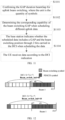
- the calculation process is shown in FIG. 3 , including following steps.
- Step S301 a UE firstly calculates a quantity of REs (Resource Elements) allocated in one PRB (Physical Resource Block).
- one PRB includes 12 frequency-domain units.
- Step S302 the UE calculates a total quantity of REs allocated to the PDSCH.
- N RE min 156 N RE ′ ⁇ n PRB , where n PRB is the quantity of PRBs allocated to the PDSCH, and is indicated by the frequency-domain parameter of the scheduling signaling.
- Step 303 calculate the TB size according to N RE , the code rate, the modulation order, and the quantity of layers.
- N RE the code rate
- modulation order the modulation order
- quantity of layers the quantity of layers.
- time-domain scheduling parameter of the PDSCH or PUSCH Physical Uplink Shared Channel
- GAP Physical Uplink Shared Channel
- FIG. 4 The schematic diagram of comparison of the required data time-domain indication content with and without a switching GAP (scenarios with only one switching length) is as shown in FIG. 4 , where cases from top to bottom are cases when there is no beam switching GAP, when there is 1 beam switching GAP, when there are 2 beams switching GAPs, and when there are 2 beams switching GAPs, respectively.
- embodiments of the disclosure provide a method, UE and base station for time-domain parameter indication of data transmission.
- the method of DCI explicit indication or implicit indication through a determination rule is used to determine whether a beam switching GAP is included in data scheduling, and the calculation method of the TB size is revised to achieve the purpose of reducing the impact on the protocol and reducing the implementation complexity of the UE and the base station in the high-frequency scheduling design.
- the method, the base station and the UE are based on the same application concept. Since the method, the base station and the UE have similar principles to solve problems, the implementations of the base station, the UE and the method may refer to each other, and the repeated description thereof will be omitted.
- Embodiment 1 As shown in FIG. 5 , an embodiment of the disclosure provides a system for time-domain parameter indication of data transmission, including: a base station 500, configured to indicate to a UE whether scheduled data includes a beam switching time interval GAP through indication information carried in DCI, or make an agreement with the UE to determine whether the scheduled data includes the GAP through a scheduling condition; determine the GAP according to a UE switching capability parameter agreed by an interface protocol when determining that the GAP is included; and transmit the scheduled data on a beam after the GAP; a UE 510, configured to determine whether scheduled data includes a beam switching time interval GAP through indication information carried in received DCI or through a scheduling condition agreed with the base station; determine the GAP according to a UE switching capability parameter agreed by an interface protocol when determining that the GAP is included; and transmit the scheduled data on a beam after the GAP.
- a base station 500 configured to indicate to a UE whether scheduled data includes a beam switching time interval GAP through indication information carried in DCI, or
- GSM Global System of Mobile communication
- CDMA Code Division Multiple Access
- WCDMA Wideband Code Division Multiple Access
- GPRS General Packet Radio Service
- LTE Long Term Evolution
- FDD Frequency Division Duplex
- TDD Time Division Duplex
- UMTS Universal Mobile Telecommunication System
- WiMAX Worldwide interoperability for Microwave Access
- 5G system and 5G NR system etc.
- GSM Global System of Mobile communication
- CDMA Code Division Multiple Access
- WCDMA Wideband Code Division Multiple Access
- GPRS General Packet Radio Service
- LTE Long Term Evolution
- FDD Frequency Division Duplex
- TDD Time Division Duplex
- UMTS Universal Mobile Telecommunication System
- WiMAX Worldwide interoperability for Microwave Access
- the user equipment UE involved in embodiments of the disclosure can refer to the device for providing the voice and/or data connectivity to the user, the handheld device with the wireless connection function, or other processing device connected to the wireless modem.
- the terminal device may have different names.
- the terminal device may be referred to as User Equipment (UE).
- the wireless terminal device may communicate with one or more core networks via the Radio Access Network (RAN), and the wireless terminal device may be a mobile terminal, such as a mobile telephone (or called "cellular" telephone), and a computer with the mobile terminal, for example, may be a portable, pocket, handheld, computer built-in or vehicle-carried mobile device, and they exchange the voice and/or data with the radio access network.
- RAN Radio Access Network
- PCS Personal Communication Service
- SIP Session Initiation Protocol
- WLL Wireless Local Loop
- PDA Personal Digital Assistant
- the wireless terminal device may also be called system, subscriber unit, subscriber station, mobile station, mobile, remote station, access point, remote terminal, access terminal, user terminal, user agent, user device, which is not limited in embodiments of the disclosure.
- the base station involved in embodiments of the disclosure may include a plurality of cells.
- the base station may also be called access point, or may refer to the device in the access network communicating with the wireless terminal via one or more sectors over the air interface or other names.
- the network device may be used to perform the inter-conversion between the received air frame and Internet Protocol (IP) packet, and used as the router between the wireless terminal device and the rest of the access network, where the rest of the access network may include IP networks.
- IP Internet Protocol
- the network device may further coordinate the attribute management of the air interface.
- the network device involved in embodiments of the disclosure can be a network device (Base Transceiver Station (BTS)) in the Global System For Mobile communications (GSM) or Code Division Multiple Access (CDMA), or can be a network device (NodeB) in the Wide-band Code Division Multiple Access (WCDMA), or can be an evolutional network device (evolutional NodeB (eNB or e-NodeB)) in the Long Term Evolution (LTE) system, a 5G base station in the 5G network architecture (Next generation System), or can be a Home evolved NodeB (HeNB), a relay node, femto, pico, etc., which is not limited in embodiments of the disclosure.
- BTS Base Transceiver Station
- GSM Global System For Mobile communications
- CDMA Code Division Multiple Access
- NodeB Wide-band Code Division Multiple Access
- WCDMA Wide-band Code Division Multiple Access
- eNB Evolutional NodeB
- eNB Evolution-NodeB
- HeNB Home evolved NodeB
- transmitting the scheduled data on the beam after the GAP refers to transmitting a valid scheduled data signal.
- valid scheduled data signal is illustrated as follows: generally, the base station and the terminal need to execute the beam switching process at the determined beam switching position, and the data sending or receiving is interrupted during the beam switching process; due to considering different hardware capabilities, one of the base station and the terminal may complete the beam switching process in advance but still think that the received or sent signal is invalid or bad during the actual execution process, that is, this signal cannot be considered as a valid signal or channel.
- the valid scheduled data signal mentioned above is a signal that meets standard requirements. In the beam switching time interval GAP, the base station does not send any signal, or the sent signal is invalid, that is, cannot be used as a valid received signal for data demodulation.
- the base station notifies the UE of whether the scheduled data includes a GAP through the DCI, or makes an agreement with the UE to determine whether the scheduled data includes a GAP through the scheduling condition.
- the base station and the UE use the agreed scheduling condition to determine whether the scheduled data includes the GAP, and the base station does not need to indicate through signaling.
- the scheduled data does not include the GAP when any of following scheduling conditions is met: a delay between a start symbol of the scheduled data indicated by DCI scheduling and a last symbol of a PDCCH of the DCI is less than a preset threshold; a length of scheduled PDSCH or PUSCH data is less than a preset length; a start position of the scheduled data is at an SS or a PBCH signal; the start position of the scheduled data is at a first symbol after conversion of an uplink signal or a downlink signal; the scheduled data is data configured by high-layer signaling; the scheduled data is data scheduled by a specific DCI format, such as the DCI format based on format 0 in the existing NR.
- the scheduled data may include a GAP, and the GAP is determined according to the UE switching capability parameter agreed in the interface protocol when determining that the GAP is included.
- Bit information is added to the DCI of the PDCCH channel to indicate whether the time-domain information of the scheduled data includes a beam switching symbol.
- This may be indicated to the UE through the indication information carried in the DCI in any of following ways.
- Different values of one bit are used for indicating whether the scheduled data includes the GAP, for example, 0 indicates that the beam switching time is included, and 1 indicates that the beam switching time is not included, or vice versa.
- Different values of two bits are used for indicating whether the scheduled data includes the GAP and the corresponding switching position when the GAP is included. Following methods may be used.
- the switching positions of the GAP are respectively located at the first symbol and the last symbol of the scheduled data in the time domain.
- the switching position of the GAP is located at the first symbol of the scheduled data in the time domain.
- the switching position of the GAP is located at the last symbol of the scheduled data in the time domain.
- the UE and the base station may determine the GAP information according to the switching capability parameter of the UE when determining that the scheduled data includes the GAP.
- the GAP information here includes the quantity of GAP symbols and the switching position of the GAP.
- the base station and the UE may determine the GAP corresponding to different UE switching capability parameters through the interface protocol.
- the GAP here may only include the quantity of symbols of the GAP, that is, the quantity of symbols of the GAP is determined by the UE switching capability parameter, and the switching position of the GAP is determined according to switching positions corresponding to different quantities of time units defined by the interface protocol.
- the quantity of time units may be the quantity of symbols or the quantity of sampling points.
- the GAP may also include the quantity of symbols of the GAP and the switching position of the GAP at the same time.
- the UE switching capability parameter includes a UE switching capability device level related to the UE itself, and also includes at least one of subcarrier spacing, a DCI format of the scheduled data, and a transmission direction of the scheduled data.
- one or more GAP switching durations are determined as follows.
- the base station does not know the UE switching capability device level of the UE.
- different UEs in a cell may also have different UE switching capability device levels. Therefore, it is necessary to distinguish application scenarios of different UE switching capability device levels.
- the base station when determining that the UE is not in the connected state, the lowest UE switching capability device level and data parameters related to the UE switching capability are used to determine the GAP included in the scheduled data; and for the UE, when determining that the UE is not in the connected state, the lowest UE switching capability device level and the data parameters related to the UE switching capability are used to determine the GAP included in the scheduled data.
- the base station when determining that the UE enters the connected state, the base station receives the UE switching capability device level reported by the UE, and determines the GAP according to the reported UE switching capability device level and a transmission parameter of the UE switching capability.
- the GAP when determining that the UE enters the connected state, the GAP is determined according to the UE switching capability device level and the transmission parameter of the UE switching capability.
- the base station and the UE transmit valid scheduled data on the beam after the GAP, including: introducing resource overhead N beamGap PRB related to beam switching to calculate a length TBsize of a transmission block of the scheduled data when transmitting the valid scheduled data on the beam after the GAP.
- the resource overhead N beamGap PRB introduced to beam switching may be determined according to the quantity of symbols of the GAP and the quantity of symbols of the valid scheduled data, where the larger the quantity of symbols of the valid scheduled data, the smaller N beamGap PRB .
- the following method may be used.
- N beamGap PRB is determined to be 0, where the preset high threshold is greater than the preset low threshold.
- N beamGap PRB is determined according to the quantity of symbols of the GAP and the quantity of symbols of the valid scheduled data, based on the rule that the larger the quantity of symbols of the valid scheduled data, the smaller N beamGap PRB .
- N beamGap PRB is used to correct the quantity of REs allocated in one PRB, and the transmission data block size TBsize is calculated by using the corrected quantity of REs and related parameters.
- the process of calculating the transmission data block size TBsize is as follows.
- N ' RE of REs allocated in one PRB is calculated, and the process is as follows.
- N RE ′ N sc RB .
- N beamGap PRB The calculation of the variable N beamGap PRB is related to beamGaP and the quantity L of symbols of the scheduled data.
- N beamGap PRB When L is greater than or equal to 7, N beamGap PRB is 0, meaning that N beamGap PRB has negligible influence on the calculation of TB size.
- Other values are related to the quantity L, and the quantity threshold of the related L may be configured as a default value or configured by the high layer.
- the above scheduled data includes any one of PDSCH data; CSI-RS; PUSCH data. Possible implementations are given below in conjunction with the specific form of the scheduled data.
- DCI 1 bit
- the scheduled data is PDSCH
- GAP 1OS
- SCS 960KHz, where OS is an OFDM symbol.
- the process of the time-domain parameter indication of data transmission is as follows.
- Step S601 confirming the GAP duration beamGap for beam switching, where the unit is the quantity of symbols.
- this embodiment determines the beam switching capability table through the protocol, corresponding to different SCSs and UE switching capability device levels, as shown in Table 3.
- the UE switching capability device level is simply referred to as capability in this embodiment.
- the content of the above table defines the quantities of symbols corresponding to different UE switching capability parameters under different SCSs.
- the quantities of symbols described above are only reference examples, and the value thereof may be other integers or decimals, or replaced by time unit; in order to simplify the operations of the UE and the base station, it is also possible to be simplified into one capability type and one value. For example, for all SCSs greater than 480KHz, the switching value is 1 symbol.
- Step S602 determining the corresponding capability of the beam switching GAP when scheduling different data.
- the default method may be used for the process of confirming the value of the duration beamGap of the beam switching GAP, for example, the UE and the base station are both based on capability 1 by default. It is also possible to report the capability to the base station after the UE enters the connected state, and the base station replies with the capability confirmed for use. The capability confirmed by the base station for use is not higher than the capability reported by the UE. If the UE reports capability 2 to the base station, the base station replies with a confirmation that the capability may be 1 or 2 but not 3.
- the base station obtains the capability of the UE through reporting, the base station also needs to define a default capability before the capability of the UE is reported.
- different UEs in a cell may also have different capabilities. Therefore, it is necessary to distinguish application scenarios of different switching capabilities.
- Step S603 the base station indicates whether the scheduled data includes a GAP through one bit in the DCI when scheduling the data.
- the 1-bit information is added to the DCI to indicate whether the scheduled data includes a GAP.
- Beam_switch_ind 1 bit, indicating whether the scheduled data includes a beam switching GAP; for example, 0 indicates that the scheduled data includes a GAP, and 1 indicates that the scheduled data includes no GAP, or vice versa.
- the quantity of symbols of the GAP may be different when the scheduled data includes the GAP.
- Beam_switch_ind when using the C-RNTI to schedule the PDSCH, ifBeam_switch_ind is 0, it means that the quantity of symbols of beam switching is 1; when using the SI-RNTI to schedule the PDSCH, if Beam_switch_ind is 0, it means that the quantity of symbols of beam switching is 2.
- Case 1 The UE negotiates with the base station that the quantity of symbols of the beam switching GAP is 1.
- Case 2 The UE and the base station consider by default that the quantity of symbols of the beam switching GAP is 2.
- Step S604 the UE receives data according to the DCI indication, as follows.
- the UE determines the beam switching position according to the indication of Beam_switch_ind, including two cases as follows.
- Beam_switch_ind 1
- Beam_switch_ind 0
- the time-domain parameters of the scheduled data include the beam switching symbol, that is to say, the UE needs to complete the switching in scheduling the start symbol in the time domain.
- the TB size is calculated according to the beam switching information and the time-domain scheduling length.
- a variable N beamGap PRB is introduced to calculate the quantity N ' RE of REs allocated in one PRB. The process is as follows.
- Step 1 the UE firstly calculates the quantity N ' RE of REs allocated in one PRB (Physical Resource Block, including 12 frequency-domain units).
- N DMRS PRB is the header overhead of the DMRS (configured or dynamically indicated by the base station);
- N oh PRB is other overhead and is configured by the base station to the UE, and this parameter is semi-statically configured;
- N beamGap PRB is overhead introduced due to beam switching.
- N beamGap PRB The calculation of the variable N beamGap PRB is related to beamGaP and the duration of the scheduled data. The instance of the relationship is as shown in Table 2.
- N beamGap PRB When L is greater than or equal to 7, N beamGap PRB is 0, meaning that N beamGap PRB has negligible influence on the calculation of TB size.
- N beamGap PRB 0.1 may be obtained by looking up the table.
- DCI 0 bit
- the scheduled data is PDSCH/CSI-RS or PUSCH
- GAP 1OS.
- Steps 1, 2 and 4 in this implementation remain the same as those in the Implementation 1.
- the focus here is to describe how to determine whether the quantity of symbols indicated by the data includes the symbol of the beam switching GAP when Beam_switch_ind is 0 bit or when no Beam_switch_ind indication is included in the scheduling signaling.
- the base station and UE When any of the following scheduling conditions is met, the base station and UE consider that the scheduled data includes no GAP.
- the schematic diagrams of two scenarios where the scheduled data includes no beam switching GAP are as shown in FIG. 8 , where the scheduling condition 1 and scheduling condition 2 are from top to bottom in FIG. 8 .
- the time-domain information thereof is agreed through high-layer signaling (or through DCI scheduling once for a plurality of times of data scheduling). In this case, it can be considered that no beam switching GAP is included in the time-domain information of the data.
- the base station and the UE may also agree as follows: when the DCI does not include the Beam_switch_ind indication information (or when the data scheduling signaling is configured by the high layer), no beam switching GAP is included in the scheduling time-domain information by default; and the beam switching GAP is included in the scheduling information by default; or it is determined, through high-layer signaling configuration, whether the beam switching GAP is included in the scheduling time-domain information by default when the DCI does not include the Beam_switch_ind indication information.
- DCI 2 bits
- the scheduled data is PUSCH data
- GAP 1OS.
- the flow chart of the Implementation 3 of the time-domain parameter indication of data transmission is as shown in FIG. 11 .
- Step S1101 confirming the GAP duration beamGap for uplink beam switching, where the unit is the quantity of symbols.
- the quantity of symbols of the uplink channel and the length of the CP become smaller. Therefore, in the duration of a specific beam switching, the quantity of symbols of the beam switching GAP required varies for different SCSs.
- different UEs or base stations have different capabilities, and their beam switching GAPs are also different.
- a better method is to determine the uplink beam switching capability table by agreement.
- the relevant values may be the same as or different from those in the downlink. The examples of different values are as shown in the following table.
- the UE switching capability device level is simply referred to as capability in this embodiment.
- the content of the above table defines the quantities of symbols corresponding to different capability types under different SCSs.
- the quantities of symbols described above are only reference examples, and the value thereof may be other integers or decimals, or replaced by time unit; in order to simplify the operations of the UE and the base station, it is also possible to be simplified into one capability type and one value. For example, for all SCSs greater than 480KHz, the switching value is 1 symbol.
- Step S 1102 determining the corresponding capability of the beam switching GAP when scheduling different uplink data.
- the default method may be used for the process of confirming the duration beamGap of the beam switching GAP, for example, the UE and the base station are both based on capability 1 by default. It is also possible to report the capability to the base station after the UE enters the connected state, and the base station replies with the capability confirmed for use. The capability confirmed by the base station for use is not higher than the capability reported by the UE. If the UE reports capability 2 to the base station, the base station replies with a confirmation that the capability may be 1 or 2.
- the base station obtains the capability of the UE through reporting, the base station also needs to define a default capability before the capability of the UE is reported.
- different UEs in a cell may also have different capabilities. Therefore, it is necessary to distinguish application scenarios of different switching capabilities.
- a random access signal is sent or other message (such as Msg3, i.e., a message in the third step of the random access process) is sent according to the minimum beam switching GAP capability.
- Step S1103 the base station indicates whether the scheduled data includes a GAP and the beam switching position through 2 bits carried in the DCI when scheduling the data.
- the 2-bit information is added to the DCI, to indicate the beam switching information included in the time-domain information of the scheduled data and the corresponding beam switching position when the GAP is included.
- Beam_switch_ind 2 bits, indicating whether the scheduled data includes a beam switching GAP, and the position of the beam switching GAP, for example: 00: indicating that two beam switching GAPs (distributed at the first symbol and the last symbol of the scheduled data in the time domain) are included; 01: indicating that one beam switching GAP is included and is at the first one of symbols of the scheduled data; 10: indicating that one beam switching GAP is included and is at the last one of symbols of the scheduled data; 11: indicating that no beam switching GAP is included.
- the schematic diagram of symbols of beam switching is as shown in FIG. 12 , where Beam_switch_ind is 00 and Beam_switch_ind is 10 from top to bottom: when using the PDSCH scheduling scheduled by C-RNTI, if Beam_switch_ind is 00, it means that there are two beam switching GAPs in the scheduling with a length of 7 symbols, and the two beam switching GAPs are located at the start symbol 7 and symbol 13 respectively. When using the PDSCH scheduling scheduled by C-RNTI, if Beam_switch_ind is 10, it means that there is one beam switching GAP in the scheduling with a length of 7 symbols, and this beam switching GAP is located at the symbol 13.
- Step S1104 the UE receives data according to the DCI indication.
- a variable N beamGap PRB is introduced to calculate the quantity N ' RE of REs allocated in one PRB. The process is as follows.
- the UE firstly calculates the quantity N ' RE of REs allocated in one PRB (Physical Resource Block, including 12 frequency-domain units).
- N beamGap PRB The calculation of the variable N beamGap PRB is related to beamGaP and the duration of the scheduled data.
- N beamGap PRB When L is greater than or equal to 7, N beamGap PRB is 0, meaning that N beamGap PRB has negligible influence on the calculation of TB size.
- Embodiment 2 this embodiment of the disclosure provides a method for time-domain parameter indication of data transmission, which is applied to a base station. As shown in FIG. 13 , the method includes following steps.
- Step S1301 indicating to a UE whether scheduled data includes a beam switching time interval GAP through indication information carried in DCI, or making an agreement with the UE to determine whether the scheduled data includes the GAP through a scheduling condition.
- Step S1302 determining the GAP according to a UE switching capability parameter agreed by an interface protocol when determining that the GAP is included.
- Step S1303 transmitting valid scheduled data on a beam after the GAP.
- the scheduled data does not include the GAP when any of following scheduling conditions is met: a delay between a start symbol of the scheduled data indicated by DCI scheduling and a last symbol of a PDCCH of the DCI is less than a preset threshold; a length of scheduled PDSCH or PUSCH data is less than a preset length; a start position of the scheduled data is at an SS or a PBCH signal; the start position of the scheduled data is at a first symbol after conversion of an uplink signal or a downlink signal; the scheduled data is data configured by high-layer signaling; the scheduled data is data scheduled by a specific DCI format.
- the UE switching capability parameter includes a UE switching capability device level related to the UE itself, and includes at least one of subcarrier spacing, a DCI format of the scheduled data, and a transmission direction of the scheduled data.
- the determining the GAP according to the UE switching capability parameter agreed by the interface protocol includes: determining a quantity of symbols of the GAP according to the UE switching capability parameter agreed by the interface protocol; determining a switching position of the GAP according to switching positions corresponding to different quantities of time units defined by the interface protocol.
- the indicating to the UE whether the scheduled data includes the beam switching time interval GAP through the indication information carried in the DCI includes: indicating whether the scheduled data includes the GAP by different values of one bit; or indicating that the scheduled data includes the GAP and a switching position of the GAP by different values of one bit; or indicating whether the scheduled data includes the GAP and a switching position of the GAP by different values of two bits.
- the scheduled data includes any one of PDSCH data; CSI-RS; PUSCH data.
- transmitting the scheduled data on the beam after the GAP includes: introducing resource overhead N beamGap PRB related to beam switching to calculate a length TBsize of a transmission block of the scheduled data when transmitting the scheduled data on the beam after the GAP.
- the introducing the resource overhead N beamGap PRB related to beam switching includes: determining N beamGap PRB according to a quantity of symbols of the GAP and a quantity of symbols of the scheduled data, where the larger the quantity of symbols of the scheduled data, the smaller N beamGap PRB .
- the introducing the resource overhead N beamGap PRB related to beam switching includes: determining that N beamGap PRB is 0 when the quantity of symbols of the scheduled data is less than a preset low threshold or greater than a preset high threshold, where the preset high threshold is greater than the preset low threshold.
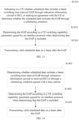
- An embodiment of the disclosure further provides a method for time-domain parameter indication of data transmission, which is applied to a UE. As shown in FIG. 14 , the method includes following steps.
- Step S 1401 determining whether scheduled data includes a beam switching time interval GAP through indication information carried in received DCI or through a scheduling condition agreed with a base station.
- Step S1402 determining the GAP according to a UE switching capability parameter agreed by an interface protocol when determining that the GAP is included.
- Step S1403 transmitting valid scheduled data on a beam after the GAP.
- the scheduled data when it is determined whether the scheduled data includes the GAP through the scheduling condition agreed with the base station, then it is determined that the scheduled data does not include the GAP when any of following scheduling conditions is met: a delay between a start symbol of the scheduled data indicated by DCI scheduling and a last symbol of a PDCCH of the DCI is less than a preset threshold; a length of scheduled PDSCH or PUSCH data is less than a preset length; a start position of the scheduled data is at an SS or a PBCH signal; the start position of the scheduled data is at a first symbol after conversion of an uplink signal or a downlink signal; the scheduled data is data configured by high-layer signaling; the scheduled data is data scheduled by a specific DCI format.
- a delay between a start symbol of the scheduled data indicated by DCI scheduling and a last symbol of a PDCCH of the DCI is less than a preset threshold
- a length of scheduled PDSCH or PUSCH data is less than a preset length
- the UE switching capability parameter includes a UE switching capability device level related to the UE itself, and includes at least one of subcarrier spacing, a DCI format of the scheduled data, and a transmission direction of the scheduled data.
- the determining the GAP according to the UE switching capability parameter agreed by the interface protocol includes: determining a quantity of symbols of the GAP according to the UE switching capability parameter agreed by the interface protocol; determining a switching position of the GAP according to switching positions corresponding to different quantities of time units defined by the interface protocol.
- the determining whether the scheduled data includes the GAP through the indication information carried in the received DCI includes: determining whether the scheduled data includes the GAP through different values of one bit carried in the DCI; or determining whether the scheduled data includes the GAP and a switching position of the GAP through different values of one bit carried in the DCI; or determining whether the scheduled data includes the GAP and a switching position of the GAP through different values of two bits carried in the DCI.
- the scheduled data includes any one of: PDSCH data; CSI-RS; PUSCH data.
- transmitting the scheduled data after beam switching in the GAP includes: introducing resource overhead N beamGap PRB related to beam switching to calculate a length TBsize of a transmission block of the scheduled data when transmitting the scheduled data on the beam after the GAP.
- the introducing the resource overhead N beamGap PRB related to beam switching includes: determining N beamGap PRB according to a quantity of symbols of the GAP and a quantity of symbols of the scheduled data, where the larger the quantity of symbols of the scheduled data, the smaller N beamGap PRB .
- the introducing the resource overhead N beamGap PRB related to beam switching includes: determining that N beamGap PRB is 0 when the quantity of symbols of the scheduled data is less than a preset low threshold or greater than a preset high threshold, where the preset high threshold is greater than the preset low threshold.
- a base station for time-domain parameter indication of data transmission provided by an embodiment of the disclosure belongs to the same inventive concept as the base station in the above Embodiment 1 of the disclosure.
- Various implementations of the time-domain parameter indication of data transmission applied to the base station in the system provided by the above embodiment may be applied to the base station for time-domain parameter indication of data transmission in this embodiment, and will not be repeated here.
- a UE for time-domain parameter indication of data transmission provided by an embodiment of the disclosure belongs to the same inventive concept as the UE in the above Embodiment 1 of the disclosure.
- Various implementations of the time-domain parameter indication of data transmission applied to the UE in the system provided by the above embodiment may be applied to the UE for time-domain parameter indication of data transmission in this embodiment, and will not be repeated here.
- Embodiment 3 this embodiment of the disclosure provides a base station for time-domain parameter indication of data transmission, as shown in FIG. 15 , including: a memory 1501, a processor 1502, a transceiver 1503 and a bus interface 1504.
- the processor 1502 is responsible for managing the bus architecture and general processing, and the memory 1501 may store the data used by the processor 1502 when performing the operations.
- the transceiver 1503 is configured to receive and send the data under the control of the processor 1502.
- the bus architecture may include any quantities of interconnected buses and bridges, and link various circuits of one or more processors represented by the processor 1502 and the memory represented by the memory 1501.
- the bus architecture may further link various other circuits such as peripheral device, voltage regulator and power management circuit, which are all well known in the art and thus will not be further described again herein.
- the bus interface provides an interface.
- the processor 1502 is responsible for managing the bus architecture and general processing, and the memory 1501 may store the data used by the processor 1502 when performing the operations.
- the procedure disclosed by embodiments of the disclosure may be applied in the processor 1502 or implemented by the processor 1502.
- each step of the signal processing flow may be completed by the integrated logic circuit of hardware in the processor 1502 or the instruction in the form of software.
- the processor 1502 may be a general-purpose processor, a digital signal processor, an application specific integrated circuit, a field programmable gate array or other programmable logic device, a discrete gate or transistor logic device, or a discrete hardware component, and may implement or perform each method, step and logical block diagram disclosed in embodiments of the disclosure.
- the general-purpose processor may be a microprocessor or any conventional processor or the like.
- the steps of the method disclosed in combination with embodiments of the disclosure may be directly completed by a hardware processor, or completed by a combination of hardware and software modules in the processor.
- the software modules may be located in the random access memory, flash memory, read only memory, programmable read only memory or electrically erasable programmable read only memory, register and other mature storage medium in the art.
- the storage medium is located in the memory 1501, and the processor 1502 reads the information in the memory 1501 and completes the steps of the signal processing flow in combination with its hardware.
- the processor 1502 is configured to read a program in the memory 1501 to: indicate to a UE whether scheduled data includes a beam switching time interval GAP through indication information carried in DCI, or make an agreement with the UE to determine whether the scheduled data includes the GAP through a scheduling condition; determine the GAP according to a UE switching capability parameter agreed by an interface protocol when determining that the GAP is included; transmit the valid scheduled data on a beam after the GAP.
- the processor determines that the scheduled data does not include the GAP when any of following scheduling conditions is met: a delay between a start symbol of the scheduled data indicated by DCI scheduling and a last symbol of a PDCCH of the DCI is less than a preset threshold; a length of scheduled PDSCH or PUSCH data is less than a preset length; a start position of the scheduled data is at an SS or a PBCH signal; the start position of the scheduled data is at a first symbol after conversion of an uplink signal or a downlink signal; the scheduled data is data configured by high-layer signaling; the scheduled data is data scheduled by a specific DCI format.
- the UE switching capability parameter includes a UE switching capability device level related to the UE itself, and includes at least one of subcarrier spacing, a DCI format of the scheduled data, and a transmission direction of the scheduled data.
- the processor determines the GAP according to the UE switching capability parameter agreed by the interface protocol by: determining a quantity of symbols of the GAP according to the UE switching capability parameter agreed by the interface protocol; determining a switching position of the GAP according to switching positions corresponding to different quantities of time units defined by the interface protocol.
- the processor indicates to the UE whether the scheduled data includes the beam switching time interval GAP through the indication information carried in the DCI by: indicating whether the scheduled data includes the GAP by different values of one bit; or indicating that the scheduled data includes the GAP and a switching position of the GAP by different values of one bit; or indicating whether the scheduled data includes the GAP and a switching position of the GAP by different values of two bits.
- the scheduled data includes any one of: PDSCH data; CSI-RS; PUSCH data.
- the processor transmits the scheduled data on the beam after the GAP by: introducing resource overhead N beamGap PRB related to beam switching to calculate a length TBsize of a transmission block of the scheduled data when transmitting the scheduled data on the beam after the GAP.
- the processor introduces the resource overhead N beamGap PRB related to beam switching by: determining N beamGap PRB according to a quantity of symbols of the GAP and a quantity of symbols of the scheduled data, where the larger the quantity of symbols of the scheduled data, the smaller N beamGap PRB .
- the processor introduces the resource overhead N beamGap PRB related to beam switching by: determining that N beamGap PRB is 0 when the quantity of symbols of the scheduled data is less than a preset low threshold or greater than a preset high threshold, where the preset high threshold is greater than the preset low threshold.
- An embodiment of the disclosure provides a UE for time-domain parameter indication of data transmission, as shown in FIG. 16 , including: a memory 1601, a processor 1602, a transceiver 1603 and a bus interface 1604.
- the processor 1602 is responsible for managing the bus architecture and general processing, and the memory 1601 may store the data used by the processor 1602 when performing the operations.
- the transceiver 1603 is configured to receive and send the data under the control of the processor 1602.
- the bus architecture may include any quantities of interconnected buses and bridges, and specifically link various circuits of one or more processors represented by the processor 1602 and the memory represented by the memory 1601.
- the bus architecture may further link various other circuits such as peripheral device, voltage regulator and power management circuit, which are all well known in the art and thus will not be further described again herein.
- the bus interface provides an interface.
- the processor 1602 is responsible for managing the bus architecture and general processing, and the memory 1601 may store the data used by the processor 1602 when performing the operations.
- the procedure disclosed by embodiments of the disclosure may be applied in the processor 1602 or implemented by the processor 1602.
- each step of the signal processing flow may be completed by the integrated logic circuit of hardware in the processor 1602 or the instruction in the form of software.
- the processor 1602 may be a general-purpose processor, a digital signal processor, an application specific integrated circuit, a field programmable gate array or other programmable logic device, a discrete gate or transistor logic device, or a discrete hardware component, and may implement or perform each method, step and logical block diagram disclosed in embodiments of the disclosure.
- the general-purpose processor may be a microprocessor or any conventional processor or the like.
- the steps of the method disclosed in combination with embodiments of the disclosure may be directly completed by a hardware processor, or completed by a combination of hardware and software modules in the processor.
- the software modules may be located in the random access memory, flash memory, read only memory, programmable read only memory or electrically erasable programmable read only memory, register and other mature storage medium in the art.
- the storage medium is located in the memory 1601, and the processor 1602 reads the information in the memory 1601 and completes the steps of the signal processing flow in combination with its hardware.
- the processor 1602 is configured to read a program in the memory 1601 to: determine whether scheduled data includes a beam switching time interval GAP through indication information carried in received DCI or through a scheduling condition; determine the GAP according to a UE switching capability parameter agreed by an interface protocol when determining that the GAP is included; transmit the valid scheduled data on a beam after the GAP.
- the processor determines whether the scheduled data includes the GAP through the scheduling condition agreed with a base station, and then the processor determines that the scheduled data does not include the GAP when any of following scheduling conditions is met: a delay between a start symbol of the scheduled data indicated by DCI scheduling and a last symbol of a PDCCH of the DCI is less than a preset threshold; a length of scheduled PDSCH or PUSCH data is less than a preset length; a start position of the scheduled data is at an SS or a PBCH signal; the start position of the scheduled data is at a first symbol after conversion of an uplink signal or a downlink signal; the scheduled data is data configured by high-layer signaling; the scheduled data is data scheduled by a specific DCI format.
- the UE switching capability parameter includes a UE switching capability device level related to the UE itself, and includes at least one of subcarrier spacing, a DCI format of the scheduled data, and a transmission direction of the scheduled data.
- the processor determines the GAP according to the UE switching capability parameter agreed by the interface protocol by: determining a quantity of symbols of the GAP according to the UE switching capability parameter agreed by the interface protocol; determining a switching position of the GAP according to switching positions corresponding to different quantities of time units defined by the interface protocol.
- the processor determines whether the scheduled data includes the GAP through the indication information carried in the received DCI by: determining whether the scheduled data includes the GAP through different values of one bit carried in the DCI; or determining whether the scheduled data includes the GAP and a switching position of the GAP through different values of one bit carried in the DCI; or determining whether the scheduled data includes the GAP and a switching position of the GAP through different values of two bits carried in the DCI.
- the scheduled data includes any one of: PDSCH data; CSI-RS; PUSCH data.
- the processor transmits the scheduled data after beam switching in the GAP by: introducing resource overhead N beamGap PRB related to beam switching to calculate a length TBsize of a transmission block of the scheduled data when transmitting the scheduled data on the beam after the GAP.
- the processor introduces the resource overhead N beamGap PRB related to beam switching by: determining N beamGap PRB according to a quantity of symbols of the GAP and a quantity of symbols of the scheduled data, where the larger the quantity of symbols of the scheduled data, the smaller N beamGap PRB .
- the processor introduces the resource overhead N beamGap PRB related to beam switching by: determining that N beamGap PRB is 0 when the quantity of symbols of the scheduled data is less than a preset low threshold or greater than a preset high threshold, where the preset high threshold is greater than the preset low threshold.
- the base station for time-domain parameter indication of data transmission belongs to the same inventive concept as the base station in the above Embodiment 1 of the disclosure.
- Various implementations of the time-domain parameter indication of data transmission applied to the base station in the system provided by the above embodiment may be applied to the base station for time-domain parameter indication of data transmission in this embodiment, and will not be repeated here.
- the UE for time-domain parameter indication of data transmission provided by embodiments of the disclosure belongs to the same inventive concept as the UE in the above Embodiment 1 of the disclosure.
- Various implementations of the time-domain parameter indication of data transmission applied to the UE in the system provided by the above embodiment may be applied to the UE for time-domain parameter indication of data transmission in this embodiment, and will not be repeated here.
- An embodiment of the disclosure provides a base station for time-domain parameter indication of data transmission, as shown in FIG. 17 , including: an indication determining unit 1701 configured to indicate to a UE whether scheduled data includes a beam switching time interval GAP through indication information carried in DCI, or make an agreement with the UE to determine whether the scheduled data includes the GAP through a scheduling condition; a GAP determining unit 1702 configured to determine the GAP according to a UE switching capability parameter agreed by an interface protocol when determining that the GAP is included; a data transmission unit 1703 configured to transmit valid scheduled data on a beam after the GAP.
- the indication determining unit makes the agreement with the UE to determine whether the scheduled data includes the GAP through the scheduling condition, then it is determined that the scheduled data does not include the GAP when any of following scheduling conditions is met: a delay between a start symbol of the scheduled data indicated by DCI scheduling and a last symbol of a PDCCH of the DCI is less than a preset threshold; a length of scheduled PDSCH or PUSCH data is less than a preset length; a start position of the scheduled data is at an SS or a PBCH signal; the start position of the scheduled data is at a first symbol after conversion of an uplink signal or a downlink signal; the scheduled data is data configured by high-layer signaling; the scheduled data is data scheduled by a specific DCI format.
- the UE switching capability parameter includes a UE switching capability device level related to the UE itself, and includes at least one of subcarrier spacing, a DCI format of the scheduled data, and a transmission direction of the scheduled data.
- the indication determining unit determines the GAP according to the UE switching capability parameter agreed by the interface protocol by: determining a quantity of symbols of the GAP according to the UE switching capability parameter agreed by the interface protocol; determining a switching position of the GAP according to switching positions corresponding to different quantities of time units defined by the interface protocol.
- the indication determining unit indicates to the UE whether the scheduled data includes the beam switching time interval GAP through the indication information carried in the DCI by: indicating whether the scheduled data includes the GAP by different values of one bit; or indicating that the scheduled data includes the GAP and a switching position of the GAP by different values of one bit; or indicating whether the scheduled data includes the GAP and a switching position of the GAP by different values of two bits.
- the scheduled data includes any one of: PDSCH data; CSI-RS; PUSCH data.
- the data transmission unit transmits the scheduled data on the beam after the GAP by: introducing resource overhead N beamGap PRB related to beam switching to calculate a length TBsize of a transmission block of the scheduled data when transmitting the scheduled data on the beam after the GAP.
- the data transmission unit introduces the resource overhead N beamGap PRB related to beam switching by: determining N beamGap PRB according to a quantity of symbols of the GAP and a quantity of symbols of the scheduled data, where the larger the quantity of symbols of the scheduled data, the smaller N beamGap PRB .
- the data transmission unit introduces the resource overhead N beamGap PRB related to beam switching by: determining that N beamGap PRB is 0 when the quantity of symbols of the scheduled data is less than a preset low threshold or greater than a preset high threshold, where the preset high threshold is greater than the preset low threshold.
- An embodiment of the disclosure provides a UE for time-domain parameter indication of data transmission, as shown in FIG. 18 , including: a receiving and determining unit 1801 configured to determine whether scheduled data includes a beam switching time interval GAP through indication information carried in received DCI or through a scheduling condition; a determining unit 1802 configured to determine the GAP according to a UE switching capability parameter agreed by an interface protocol when determining that the GAP is included; a transmission unit 1803 configured to transmit valid scheduled data on a beam after the GAP.
- the receiving and determining unit determines whether the scheduled data includes the GAP through the scheduling condition agreed with the base station, then it is determined that the scheduled data does not include the GAP when any of following scheduling conditions is met: a delay between a start symbol of the scheduled data indicated by DCI scheduling and a last symbol of a PDCCH of the DCI is less than a preset threshold; a length of scheduled PDSCH or PUSCH data is less than a preset length; a start position of the scheduled data is at an SS or a PBCH signal; the start position of the scheduled data is at a first symbol after conversion of an uplink signal or a downlink signal; the scheduled data is data configured by high-layer signaling; the scheduled data is data scheduled by a specific DCI format.
- the UE switching capability parameter includes a UE switching capability device level related to the UE itself, and includes at least one of subcarrier spacing, a DCI format of the scheduled data, and a transmission direction of the scheduled data.
- the receiving and determining unit determines the GAP according to the UE switching capability parameter agreed by the interface protocol by: determining a quantity of symbols of the GAP according to the UE switching capability parameter agreed by the interface protocol; determining a switching position of the GAP according to switching positions corresponding to different quantities of time units defined by the interface protocol.
- the receiving and determining unit determines whether the scheduled data includes the GAP through the indication information carried in the received DCI by: determining whether the scheduled data includes the GAP through different values of one bit carried in the DCI; or determining whether the scheduled data includes the GAP and a switching position of the GAP through different values of one bit carried in the DCI; or determining whether the scheduled data includes the GAP and a switching position of the GAP through different values of two bits carried in the DCI.
- the scheduled data includes any one of: PDSCH data; CSI-RS; PUSCH data.
- the transmission unit transmits the scheduled data after beam switching in the GAP by: introducing resource overhead N beamGap PRB related to beam switching to calculate a length TBsize of a transmission block of the scheduled data when transmitting the scheduled data on the beam after the GAP.
- the transmission unit introduces the resource overhead N beamGap PRB related to beam switching by: determining N beamGap PRB according to a quantity of symbols of the GAP and the quantity of symbols of the scheduled data, where the larger the quantity of symbols of the scheduled data, the smaller N beamGap PRB .
- the transmission unit introduces the resource overhead N beamGap PRB related to beam switching and is further configured to: determine that N beamGap PRB is 0 when the quantity of symbols of the scheduled data is less than a preset low threshold or greater than a preset high threshold, where the preset high threshold is greater than the preset low threshold.
- the base station for time-domain parameter indication of data transmission belongs to the same inventive concept as the base station in the above Embodiment 1 of the disclosure.
- Various implementations of the time-domain parameter indication of data transmission applied to the base station in the system provided by the above embodiment may be applied to the base station for time-domain parameter indication of data transmission in this embodiment, and will not be repeated here.
- the UE for time-domain parameter indication of data transmission provided by embodiments of the disclosure belongs to the same inventive concept as the UE in the above Embodiment 1 of the disclosure.
- Various implementations of the time-domain parameter indication of data transmission applied to the UE in the system provided by the above embodiment may be applied to the UE for time-domain parameter indication of data transmission in this embodiment, and will not be repeated here.
- An embodiment of the disclosure further provides a computer program medium storing a computer program thereon, where the program, when executed by a processor, implements the steps of the method for time-domain parameter indication of data transmission applied to the base station provided in the above Embodiment 2.
- the disclosure further provides a computer program medium storing a computer program thereon, where the program, when executed by a processor, implements the steps of the method for time-domain parameter indication of data transmission applied to the UE provided in the above Embodiment 2.
- the disclosed system, devices and methods may be implemented in other manners.
- the device embodiments described above are only schematic, for example, the division of the modules is merely a logical function division. In an actual implementation, there may be other division manners, for example, a plurality of modules or components may be combined or integrated to another system, or some features may be ignored or not performed.
- the displayed or discussed mutual coupling or direct coupling or communication connection may be implemented through the indirect coupling or communication connection between some interfaces, devices or modules, and may be in the electrical or other forms.
- modules described as separate components may or may not be physically separated, and the components displayed as modules may or may not be physical modules, that is, may be located in one place or may be distributed onto multiple network modules. Some or all of the modules may be selected according to the actual needs to achieve the objects of the solutions of embodiments.
- each module in each embodiment of the disclosure may be integrated into one processing module, or each module may exist alone physically, or two or more modules may be integrated into one module.
- the above-mentioned integrated modules can be implemented in the form of hardware, or can be implemented in the form of software functional modules.
- the integrated module When the integrated module is implemented in the form of software functional module and sold or used as an independent product, it may be stored in a computer readable storage medium.
- the above embodiments may be implemented in whole or in part by software, hardware, firmware or any combination thereof.
- When implemented by software they may be implemented in the form of a computer program product in whole or in part.
- the computer program product includes one or more computer instructions.
- the computer may be a general-purpose computer, a special-purpose computer, a computer network, or other programmable devices.
- the computer instructions may be stored in a computer readable storage medium or transmitted from a computer readable storage medium to another computer readable storage medium.
- the computer instructions may be transmitted from a website, computer, server or data center to another website, computer, server or data center in a wired (e.g., coaxial cable, optical fiber, Digital Subscriber Line (DSL)) or wireless (e.g., infrared, wireless, microwave, etc.) way.
- a wired e.g., coaxial cable, optical fiber, Digital Subscriber Line (DSL)
- wireless e.g., infrared, wireless, microwave, etc.
- the computer readable storage medium may be any available medium that can be stored by a computer, or a data storage device such as server or data center that is integrated with one or more available media.
- the available medium may be a magnetic medium (for example, floppy disk, hard disk, magnetic tape), an optical medium (for example, DVD), or a semiconductor medium (for example, Solid State Disk (SSD)), etc.
- embodiments of the disclosure can be provided as methods, systems and computer program products.
- the disclosure can take the form of hardware embodiments alone, software embodiments alone, or embodiments combining the software and hardware aspects.
- the disclosure can take the form of computer program products implemented on one or more computer usable storage mediums (including but not limited to magnetic disk memories, CD-ROMs, optical memories and the like) including computer usable program codes therein.
- These computer program instructions can also be stored in a computer readable memory which is capable of guiding the computer or another programmable data processing device to operate in a particular way, so that the instructions stored in the computer readable memory produce a manufacture including the instruction apparatus which implements the functions specified in one or more processes of the flow charts and/or one or more blocks of the block diagrams.
- These computer program instructions can also be loaded onto the computer or another programmable data processing device, so that a series of operation steps are performed on the computer or another programmable device to produce the computer-implemented processing.
- the instructions executed on the computer or another programmable device provide steps for implementing the functions specified in one or more processes of the flow charts and/or one or more blocks of the block diagrams.
Landscapes
- Engineering & Computer Science (AREA)
- Signal Processing (AREA)
- Computer Networks & Wireless Communication (AREA)
- Databases & Information Systems (AREA)
- Physics & Mathematics (AREA)
- Mathematical Physics (AREA)
- Mobile Radio Communication Systems (AREA)
Applications Claiming Priority (2)
| Application Number | Priority Date | Filing Date | Title |
|---|---|---|---|
| CN202010734682.4A CN113993211B (zh) | 2020-07-27 | 2020-07-27 | 一种数据传输时域参数指示的方法和ue及基站 |
| PCT/CN2021/106846 WO2022022302A1 (zh) | 2020-07-27 | 2021-07-16 | 一种数据传输时域参数指示的方法和ue及基站 |
Publications (2)
| Publication Number | Publication Date |
|---|---|
| EP4192163A1 true EP4192163A1 (de) | 2023-06-07 |
| EP4192163A4 EP4192163A4 (de) | 2023-12-20 |
Family
ID=79731582
Family Applications (1)
| Application Number | Title | Priority Date | Filing Date |
|---|---|---|---|
| EP21851256.4A Pending EP4192163A4 (de) | 2020-07-27 | 2021-07-16 | Verfahren zur anzeige von datenübertragungszeitbereichsparametern, benutzergerät und basisstation |
Country Status (6)
| Country | Link |
|---|---|
| US (1) | US20230269727A1 (de) |
| EP (1) | EP4192163A4 (de) |
| JP (1) | JP7481570B2 (de) |
| KR (1) | KR102927331B1 (de) |
| CN (1) | CN113993211B (de) |
| WO (1) | WO2022022302A1 (de) |
Families Citing this family (1)
| Publication number | Priority date | Publication date | Assignee | Title |
|---|---|---|---|---|
| EP4518427A4 (de) * | 2022-04-29 | 2025-06-18 | Beijing Xiaomi Mobile Software Co., Ltd. | Uplink-übertragungsverfahren und -vorrichtung sowie speichermedium |
Family Cites Families (17)
| Publication number | Priority date | Publication date | Assignee | Title |
|---|---|---|---|---|
| US20190104549A1 (en) * | 2014-11-26 | 2019-04-04 | Idac Holdings, Inc. | Initial access in high frequency wireless systems |
| CN106612559B (zh) * | 2015-10-27 | 2019-12-24 | 华为技术有限公司 | 时隙调度方法及装置 |
| WO2017125129A1 (en) * | 2016-01-19 | 2017-07-27 | Nokia Solutions And Networks Oy | Guard period between subframe portions of same link direction in wireless networks |
| WO2017146759A1 (en) * | 2016-02-25 | 2017-08-31 | Intel IP Corporation | Device and method for synchronous beam switching |
| US10123322B1 (en) * | 2017-09-18 | 2018-11-06 | Qualcomm Incorporated | Transmission of beam switch commands through control channel signaling |
| US10764932B2 (en) * | 2018-03-23 | 2020-09-01 | Qualcomm Incorporated | Beam switch and beam failure recovery |
| US11129170B2 (en) * | 2018-05-10 | 2021-09-21 | Qualcomm Incorporated | Methods and systems for protecting high priority symbols from beam switching |
| CN110536456B (zh) * | 2018-05-25 | 2022-03-25 | 成都华为技术有限公司 | 通信方法、终端设备和网络设备 |
| WO2020032432A1 (en) * | 2018-08-09 | 2020-02-13 | Lg Electronics Inc. | Method of transmitting and receiving channel state information in wireless communication system and apparatus therefor |
| CN110933749B (zh) * | 2018-09-20 | 2023-04-07 | 成都华为技术有限公司 | 指示波束的方法和装置 |
| CN110536432B (zh) * | 2018-09-21 | 2025-07-22 | 中兴通讯股份有限公司 | 一种信息传输的方法、装置和设备 |
| US11632740B2 (en) * | 2018-10-04 | 2023-04-18 | Qualcomm Incorporated | Multicast or broadcast ethernet traffic transmissions over a radio access network |
| US11265881B2 (en) * | 2018-11-02 | 2022-03-01 | Qualcomm Incorporated | Implicit radio link monitoring resource configuration |
| US11405088B2 (en) * | 2019-02-07 | 2022-08-02 | Qualcomm Incorporated | Beam management using channel state information prediction |
| US11700599B2 (en) * | 2019-10-10 | 2023-07-11 | Qualcomm Incorporated | Beam switching gap |
| US11909481B2 (en) * | 2020-04-09 | 2024-02-20 | Qualcomm Incorporated | Default channel state information (CSI)-reference signal (RS) beam |
| US12245212B2 (en) * | 2020-07-02 | 2025-03-04 | Qualcomm Incorporated | Bandwidth part switching |
-
2020
- 2020-07-27 CN CN202010734682.4A patent/CN113993211B/zh active Active
-
2021
- 2021-07-16 US US18/015,078 patent/US20230269727A1/en active Pending
- 2021-07-16 EP EP21851256.4A patent/EP4192163A4/de active Pending
- 2021-07-16 KR KR1020237005921A patent/KR102927331B1/ko active Active
- 2021-07-16 WO PCT/CN2021/106846 patent/WO2022022302A1/zh not_active Ceased
- 2021-07-16 JP JP2023504406A patent/JP7481570B2/ja active Active
Also Published As
| Publication number | Publication date |
|---|---|
| US20230269727A1 (en) | 2023-08-24 |
| KR102927331B1 (ko) | 2026-02-12 |
| JP2023535425A (ja) | 2023-08-17 |
| CN113993211A (zh) | 2022-01-28 |
| WO2022022302A1 (zh) | 2022-02-03 |
| JP7481570B2 (ja) | 2024-05-10 |
| CN113993211B (zh) | 2025-04-15 |
| EP4192163A4 (de) | 2023-12-20 |
| KR20230042076A (ko) | 2023-03-27 |
Similar Documents
| Publication | Publication Date | Title |
|---|---|---|
| US12089223B2 (en) | Signal reception or transmission method and apparatus and system | |
| US11229046B2 (en) | Data transmission method and terminal | |
| CN113677014B (zh) | 一种确定反馈信息传输位置的方法及设备 | |
| WO2020143524A1 (zh) | 传输下行信道的方法和装置 | |
| EP3648389A1 (de) | Kommunikationsverfahren, netzwerkvorrichtung und relaisvorrichtung | |
| EP3703298A1 (de) | Informationsübertragungsverfahren und -vorrichtung | |
| WO2022151868A1 (zh) | 一种dmrs绑定窗口确定方法、装置及存储介质 | |
| WO2020216130A1 (zh) | 一种通信方法及装置 | |
| US20250343630A1 (en) | Method and apparatus for transmitting reference signal transmission and communication system | |
| CN108882382A (zh) | 传输方法、终端和网络设备 | |
| US12301507B2 (en) | Data feedback method and apparatus | |
| WO2020062068A1 (zh) | 无线通信方法、终端设备和网络设备 | |
| US20250047545A1 (en) | Method and device for configuring repeater | |
| CN114765505B (zh) | 解调参考信号dmrs的发送方法、接收方法和装置 | |
| EP4152811A1 (de) | Verfahren und vorrichtung zur cache-bestimmung | |
| TW202041072A (zh) | 通訊方法和終端設備 | |
| US11382120B2 (en) | Information transmission method and device | |
| US12477523B2 (en) | Sidelink data packet sending and receiving method and communication apparatus | |
| US20230269727A1 (en) | Data transmission time domain parameter indication method, ue, and base station | |
| EP4192042A1 (de) | Rundfunkdatenübertragungsverfahren und -vorrichtung sowie vorrichtung | |
| CN106576023A (zh) | 一种信息传输方法、设备及系统 | |
| CN107113814A (zh) | 无线通信的方法、网络设备和终端设备 | |
| WO2020133036A1 (zh) | 重复传输方法、装置、芯片及计算机程序 | |
| CN107889239A (zh) | 一种上行控制信息发送、接收方法及设备 | |
| WO2020087548A1 (zh) | 一种功率控制方法、设备及存储介质 |
Legal Events
| Date | Code | Title | Description |
|---|---|---|---|
| STAA | Information on the status of an ep patent application or granted ep patent |
Free format text: STATUS: THE INTERNATIONAL PUBLICATION HAS BEEN MADE |
|
| PUAI | Public reference made under article 153(3) epc to a published international application that has entered the european phase |
Free format text: ORIGINAL CODE: 0009012 |
|
| STAA | Information on the status of an ep patent application or granted ep patent |
Free format text: STATUS: REQUEST FOR EXAMINATION WAS MADE |
|
| 17P | Request for examination filed |
Effective date: 20230117 |
|
| AK | Designated contracting states |
Kind code of ref document: A1 Designated state(s): AL AT BE BG CH CY CZ DE DK EE ES FI FR GB GR HR HU IE IS IT LI LT LU LV MC MK MT NL NO PL PT RO RS SE SI SK SM TR |
|
| DAV | Request for validation of the european patent (deleted) | ||
| DAX | Request for extension of the european patent (deleted) | ||
| REG | Reference to a national code |
Ref country code: DE Ref legal event code: R079 Free format text: PREVIOUS MAIN CLASS: H04W0072040000 Ipc: H04W0072126300 |
|
| A4 | Supplementary search report drawn up and despatched |
Effective date: 20231121 |
|
| RIC1 | Information provided on ipc code assigned before grant |
Ipc: H04W 72/232 20230101ALN20231115BHEP Ipc: H04W 72/044 20230101ALN20231115BHEP Ipc: H04B 7/08 20060101ALN20231115BHEP Ipc: H04B 7/06 20060101ALN20231115BHEP Ipc: H04L 5/00 20060101ALI20231115BHEP Ipc: H04W 72/1263 20230101AFI20231115BHEP |