EP4193111B1 - Dispositif d'aide au chargement de chargeur - Google Patents
Dispositif d'aide au chargement de chargeur Download PDFInfo
- Publication number
- EP4193111B1 EP4193111B1 EP21735650.0A EP21735650A EP4193111B1 EP 4193111 B1 EP4193111 B1 EP 4193111B1 EP 21735650 A EP21735650 A EP 21735650A EP 4193111 B1 EP4193111 B1 EP 4193111B1
- Authority
- EP
- European Patent Office
- Prior art keywords
- magazine
- pusher
- receiving space
- cartridge
- sliding member
- Prior art date
- Legal status (The legal status is an assumption and is not a legal conclusion. Google has not performed a legal analysis and makes no representation as to the accuracy of the status listed.)
- Active
Links
Images


Classifications
-
- F—MECHANICAL ENGINEERING; LIGHTING; HEATING; WEAPONS; BLASTING
- F41—WEAPONS
- F41A—FUNCTIONAL FEATURES OR DETAILS COMMON TO BOTH SMALLARMS AND ORDNANCE, e.g. CANNONS; MOUNTINGS FOR SMALLARMS OR ORDNANCE
- F41A9/00—Feeding or loading of ammunition; Magazines; Guiding means for the extracting of cartridges
- F41A9/82—Reloading or unloading of magazines
- F41A9/83—Apparatus or tools for reloading magazines with unbelted ammunition, e.g. cartridge clips
- F41A9/84—Clips
Definitions
- the invention relates to a loading aid device according to the preamble of claim 1. Furthermore, the invention relates to a method according to the preamble of claim 15.
- Stick magazines for holding cartridges from firearms have a receiving space for the cartridges, in which they are stacked in one or two rows (the two rows are offset in height). At the upper output end, the receiving space is limited by magazine lips, which narrow the width of the receiving space and against which the topmost cartridge in the magazine rests, whereby a A magazine follower loaded by a magazine spring acts on the lowest cartridge in the magazine or, in the case of a two-row magazine, on the lowest cartridges of the two rows, in order to press the topmost cartridge in the magazine against the magazine lips.
- the cartridges are usually inserted into the stick magazine one by one by hand. They are pressed against the magazine feeder or the cartridges already in the magazine in a front area of the magazine, in front of which the magazine lips end, and are thereby inserted into a front area of the magazine's receiving space and then pushed into the rear area of the receiving space and under the magazine lips. This process is relatively strenuous and laborious.
- Loading aids for stick magazines are already known, which have a holder part that can be placed on an upper section of the stick magazine, in which the stick magazine is held in a similar way to the firearm.
- a feed part in the form of a rail with an undercut groove is attached to the holder part, into which the cartridges to be loaded are threaded before being placed on the magazine.
- the cartridges, which are arranged in a row in the feed part and rest on the top of the magazine, are then manually pressed into the magazine's receiving space using a handpiece that can be moved along the rail-shaped receiving part and rests on the top of the cartridges.
- this can speed up the loading of the magazine, the amount of force required to push the cartridges into the magazine with the handpiece is higher.
- the magazine receiving area is considerably depressed.
- a loading aid device with a mounting part that can be placed on an upper section of the rod magazine and on which an actuating part designed as a lever is pivotably mounted is known from prior use.
- actuating the actuating part a single cartridge inserted into the loading aid device is pressed by a pusher past the magazine lips into a front area of the receiving space of the rod magazine and then pushed by a pusher into the rear area of the receiving space under the magazine lips.
- the cartridges to be loaded must each be inserted individually into the loading aid device.
- the object of the invention is to provide an advantageous loading aid device of the type mentioned at the outset, which enables simple, rapid and energy-saving loading of the bar magazine. According to the invention, this is achieved by a loading aid device with the features of claim 1 or by a method with the features of claim 15.
- the loading aid device has a thrust piece which is adjustable between a passive position in which it is located completely outside the receiving space (9) of the bar magazine (2) and an active position in which a tappet section (14c) of the thrust piece projects between the magazine lips (10) into the receiving space (9) of the bar magazine (2), wherein this adjustment of the thrust piece between the passive position and the active position of the thrust piece for pressing down the magazine feeder together with any already present in the receiving space of the stick magazine. This releases a front free space in a front area of the receiving space of the stick magazine.
- the loading aid device further comprises a pusher which can be adjusted between a feed position and a pressing position.
- Adjusting the pusher from the feed position to the pressing position serves to press one of the cartridges to be loaded, which in the active position of the pusher and feed position of the pusher has been fed from the feed part into the front free space of the receiving space of the stick magazine, into a rear free space in a rear area of the receiving space, which was released by the pusher when the pusher was pulled back from the active position towards the passive position.
- the cartridge is thus completely received in the receiving space of the stick magazine.
- the cartridge is therefore in a loading position.
- the loading process is advantageously carried out by the interaction of the movement of the pusher from the passive position to the active position and back to the passive position and the coupled movement of the pusher from the pressing position to the feeding position and back to the pressing position.
- cartridges to be loaded can be accommodated by the loading aid device according to the invention, wherein several cartridges to be loaded can be inserted into the feed part and are guided displaceably by it.
- the adjustment of the pusher from the feed position to the pressing position is carried out by a tension spring which acts on the pusher in the direction of the pressing position.
- a cartridge to be loaded can thus be pushed by the trigger through the action of the tension spring into the rear area of the chamber and thus into its loading position.
- an actuating part is advantageously provided which is mechanically coupled to both the pusher and the pusher and which can be adjusted from an initial position to an actuating position.
- the actuating part is adjusted from the initial position to the actuating position, the pusher is adjusted from the pressing position to the feeding position and the pusher is adjusted from the passive position to the active position.
- the cartridge to be loaded is fed into the front free space of the receiving chamber in the active position of the pusher and in the feed position of the trigger by the effect of gravity as soon as the front free space is sufficiently large in a front area of the receiving chamber next to the tappet section and the trigger has moved sufficiently far in the direction of the feed position.
- the front free space extends to under a front section of the magazine lips, under which the cartridge comes to lie in the area of its rear end.
- the thrust piece is advantageously mounted on the support part so as to be linearly displaceable, wherein it is preferably urged into the passive position by a return spring.
- the actuating part which preferably has a handle section for actuation, is mounted on the support part so that it can pivot about an actuating part pivot axis.
- the actuating part is advantageously urged into the starting position by spring force, in particular by the return spring acting on the thrust piece and the coupling of the actuating part to the thrust piece.
- the adjustment of the thrust piece by the actuating part is advantageously carried out in a forced manner in both directions, i.e. with a continuous adjustment of the actuating part from the starting position to the actuating position, a continuous adjustment of the thrust piece from the passive position to the active position takes place and with a continuous adjustment of the actuating part from the actuating position to the starting position, a continuous return of the thrust piece from the active position to the passive position takes place.
- the coupling between the actuating part and the pusher is advantageously only forced in one direction, i.e. with a continuous adjustment of the actuating part from the starting position to the actuating position, a continuous adjustment of the pusher from the pressing position to the feed position takes place, while with a continuous adjustment of the actuating part from the actuating position to the starting position, the pusher is able to remain in the same position at least over a section of this adjustment of the actuating part.
- the pusher having at least one guide pin and the actuating part has at least one guide surface, wherein the at least one guide pin of the pusher only rests on one side against the associated guide surface of the actuating part.
- the actuating part could also have at least one guide pin that only rests on one side against a guide surface of the pusher.
- Other designs of such at least partial release of movement between the actuating part and the pusher are conceivable and possible, for example by means of a guide pin that is arranged on one of the two parts and projects into a window recess on the other of these two parts, wherein the window recess has a larger clear width than the guide pin.
- the feed part has a rail with an undercut groove.
- Several cartridges to be loaded can be threaded into this undercut groove and guided displaceably therein, with their feed to the front area of the receiving space taking place by gravity in the active position of the pusher and the pressing position of the trigger.
- top and bottom refers to an orientation in which the magazine lips of the stick magazine inserted into the loading aid device are at the top.
- the loading aid device has a holder part 1, which has a receiving opening 1a, into which a rod magazine 2 can be inserted with an upper section.
- the rod magazine 2 is held on the loading aid device after being pushed into the receiving opening 1a of the holder part 1.
- the rod magazine 2 can be held on the holder part 1 in a similar way to the usual holder of the rod magazine 2 on a firearm.
- the holder part 1 can have spring-loaded locking lugs 3a for this purpose, which engage in locking recesses 2a of the rod magazine 2.
- the locking lugs 3a can be arranged on preferably pivotably mounted locking elements 3. To open the holder and When removing the rod magazine from the receiving opening of the holder part 1, the locking elements 3 can be pivoted against the force of the springs 4 acting on the locking elements 3.
- the locking elements 3 with the locking lugs 3a are arranged on an adapter element 5, which is held on a base part 1b of the holding part 1.
- the holding part 1 can be adapted to different types of bar magazines, as used by different manufacturers.
- the base part 1b and the adapter part 5 together form a sleeve which has the receiving opening 1a.
- the rod magazine 2 can be designed in a conventional manner. It has a receiving space 9 for receiving the cartridges 8.
- the receiving space 9 is limited at the top by magazine lips 10. These only extend over a rear part of the magazine, while in a front part of the magazine there is a larger opening of the receiving space 9 upwards towards the outside, which is used to load the magazine.
- a magazine feeder 11 is arranged in the magazine, which is acted upon by a magazine spring 12 and which pushes the cartridges 8 arranged in the receiving space 9 upwards, whereby the uppermost these cartridges 8 rests on the magazine lips 10.
- a feed part 13 is fixed to the support part 1 of the loading aid device.
- This has a rail 13a with an undercut groove into which cartridges to be loaded are threaded.
- the cartridges 8 are thus guided by the feed part so that they can be moved at right angles to their longitudinal direction.
- the rail 13a is screwed to the support part 1 in the execution part by means of flanges 13b.
- the cartridges threaded into the undercut groove of the rail 13a can be moved along the rail 13a.
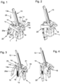
- a thrust piece 14 is arranged parallel to a displacement direction 25 between a passive position (cf. Fig. 1, 3 , 5, 8 , 9, 12 , 16 and 19 ) and an active position (cf. Fig. 2, 4 , 6 , 10 and 17 ) is mounted so that it can be moved linearly.
- a bearing pin 14a of the thrust piece 14 serves this purpose, which engages in a bearing recess in the mounting part 1.
- a return spring 15 is arranged between the bottom of this bearing recess and the bearing pin 14a. When the loading aid device is not actuated, the return spring 15 urges the thrust piece 14 into the passive position....
- a pusher 16 is provided on the mounting part 1 and can be adjusted between a pressing position (cf. Fig. 1, 3 , 5, 8 , 9, 12 , 16 and 19 ) and a feed position (cf. Fig. 2, 4 , 6 , 10 and 17 ) pivotally mounted.
- the pivotable mounting of the pusher 16 is carried out by means of a bearing pin 17 about a pusher pivot axis 18. This is perpendicular to the direction of displacement 25.
- the pusher 16 is actuated by a tension spring 19. In the unactuated state of the The tension spring 19 acts on the trigger in the loading aid device into a depressed position of the trigger 16.
- an actuating part 20 designed as a lever is pivotable about an actuating part pivot axis 21 between an initial position (cf. Fig. 1, 3 , 5, 8 , 9, 12 , 16 and 19 ) and an operating position (cf. Fig. 2, 4 , 6 , 10 and 17 ) pivotally mounted.
- the actuating part pivot axis 21 is parallel to the trigger pivot axis 18.
- the actuating part 20 has a handle section 20a which serves to actuate the loading aid device 1 by the user in order to load cartridges 8 into the rod magazine 2.
- the actuating part 20 is made of two parts.
- the handle section 20a is divided along its longitudinal center by the two parts that are screwed together.
- the two parts each have a guide extension 20b, which has a guide surface 20c.
- the two parts of the actuating part 20 in the embodiment each have an axle pin 20d which engages in a bearing bush 22 arranged in the support part 1.
- the bearing bushes 22 can also be omitted.
- a cheek 1c is attached to the top of each of the opposite broad walls of the base part 1b of the holder part 1.
- the pusher 16 and the actuating part 20 are pivotably mounted on the cheeks 1c. There is a space between the cheeks 1c for feeding the cartridges 8 to the top of the rod magazine 2.
- the handle portion 20a of the operating part 20 By operating the handle portion 20a of the operating part 20, this can be pivoted between a starting position and an actuating position.
- the thrust piece 14 is positively coupled to the actuating part 20 in both adjustment directions of the actuating part 20.
- a coupling pin 23 attached to the actuating part 20 serves this purpose, which passes through a recess 14b in the thrust piece 14. Since the actuating part 20 is pivotably mounted and the thrust piece 14 is linearly displaceable, the recess 14b is designed as an elongated hole recess.
- the thrust piece 14 When the actuating part 20 is pivoted from the starting position into the actuating position, the thrust piece 14 is moved from the passive position into an active position by the forced coupling with the actuating part 20. If the handle section 20a is released by the user, the return spring 15 moves the thrust piece 14 back into the passive position and the coupling with the actuating part 20 pivots the actuating part 20 back into the starting position.
- the pusher 16 has protruding guide pins 16a on opposite sides, which are aligned parallel to the pusher pivot axis 18 and interact with the guide surfaces 20c of the actuating part 20. If the actuating part 20 is pivoted from the starting position into the actuating position, the interaction of the guide pins 16a with the guide surfaces 20c causes the pusher 16 to pivot from the pressing position into the feed position of the pusher 16.
- the guide pins 16a are The tension spring 19 is held in contact with the guide surfaces 20c and the pusher 16 is moved back into the pressing position. However, this is not mandatory. If the pusher 16 is held in the feed position, the actuating part 20 can still swing back into the starting position by lifting the guide pins 16a off the guide surfaces 20c. Such lifting of the guide pins 16a from the guide surfaces 20c over a section of the return of the actuating part 20 from the actuating position to the starting position takes place during the loading process, as is explained in more detail below.
- FIG. 5 to 8 , 9 to 12 and 16 to 19 show different phases of the charging process.
- the Fig. 5 , 9 and 16 show the state at the beginning of the loading process.
- the rod magazine 2 is held in the receiving opening 1a of the holder part 1 and cartridges 8 are threaded into the undercut groove of the rail 13a of the feed part 13.
- the cartridges slide downwards along the rail 13a due to the effect of gravity until the lowest cartridge rests on a support surface 16b of the pusher 16 which is in the pressing position.
- the pusher 14 is moved from the passive position to the active position.
- a tappet section 14c of the pusher 14 moves through the space between the magazine lips 10 into a rear area of the receiving space 9. If cartridges 8 are already arranged in the receiving space 9, the tappet section 14c presses on the topmost of these cartridges 8 and presses these together with any cartridges lying underneath and the magazine feeder 11 downwards against the force of the magazine spring 12. If there are no cartridges 8 in the receiving space 9, the tappet section 14c presses directly against the magazine feeder 11 and presses it downwards. This creates a front free space in a front area of the receiving space 9. This extends to under a front section of the magazine lips 10.
- the coupling with the pusher 16 causes the pusher 16 to pivot about the pusher pivot axis 18 from the pressing position to the feed position.
- this pivoting of the pusher 16 occurs by the guide pins 16a of the pusher 16 resting on the guide surfaces 20c of the actuating part 20.
- the support surface 16b of the pusher By pivoting the pusher 16 from the pressing position to the feeding position, the support surface 16b of the pusher, on which the lowest of the cartridges 8 arranged in the feeding part 13 rests, is moved towards the front end of the cartridge and subsequently pivoted away from the cartridge.
- the support surface 16b of the pusher 16 slides downwards, sliding out of the lower end of the guide of the feeding part 13 and falling through the opening in front of the magazine lips 10 on the top of the rod magazine 2 into the front free space in the front area of the receiving space 8 of the rod magazine 2, which is released by the action of the pusher 14, and sliding backwards in this space until it rests against a side surface of the tappet section 14c of the pusher 14.
- the cartridge 8 then rests in the area of its rear end on the topmost cartridge 8 already located in the receiving space 9 or, if such is not present, on the magazine feeder 11. This rear end of the cartridge 8 lies below the magazine lips 10. In a front section, the cartridge 8 can rest on the upper edge of the rod magazine 2. It would also be possible to rest on a part of the loading aid. This situation is shown in the Fig. 6 , 10 and 17 The position of this cartridge to be loaded is best seen from Fig. 17 is visible. The next upper cartridge in the feed part 13 rests on the upper side of this cartridge which is currently being loaded.
- the actuating part is then moved from the actuating position back to the starting position. This can be done by releasing the actuating part 20 and the effect of the return spring 15.
- the Fig. 7 , 11 and 18 show an intermediate position of the actuating part 20 during resetting.
- the tappet section 14c of the pusher 14 is increasingly raised. Since the cartridge 8 to be loaded is located with its rear side below the magazine lips 10, the magazine feeder 11 is blocked from moving upwards with the possibly already fully loaded cartridges 8. The cartridge to be loaded is clamped with its rear end between the magazine lips 10 and the topmost of the cartridges 8 already located in the receiving space 9 or, if none is present, the magazine feeder 11. The pusher 16 pivots increasingly from the feed position towards the pressing position until it is at the top of the Cartridge is in contact. At the moment in which the pusher 16 comes into contact with the tip of the cartridge 8, the cartridge 8 is still in contact with the tappet section 14c with its rear side.
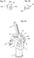
- the optional accessory in the Fig. 21 and 22 a single cartridge feed piece is shown.
- This can be inserted into the undercut groove of the feed part 13 with laterally protruding guide strips 24a, cf. Fig. 23 . It slides downwards until it rests against the holder part 1.
- the single cartridge feed piece 24 has an opening 24b into which a cartridge can be inserted, cf. Fig. 23 .
- the support surface 16b disengages from the cartridge 8 and the latter can slide into the released front space in the receiving space 9 of the rod magazine 2, analogously to the feeding via the feeding part 13.
- a feed part analogous to the single cartridge feed piece 24 could also be provided, by which a single cartridge is slidably guided and which could then be fixedly mounted on the holder part 1. The cartridges to be loaded would then have to be fed individually by the user into the single cartridge feed piece.
- the thrust piece 14 could be mounted in a different way on the support part 1.
- a pivotably mounted arrangement of a thrust piece would also be conceivable and possible.
- a return spring acting on the thrust piece 14 could also be provided.
- the cartridges 8 can be arranged in the receiving space 9 of the rod magazine 2 in one row or in two rows (offset in height).
- a linearly movable handle could also be provided.
- a linearly displaceable actuating part could in principle also be provided.
- a motorized adjustment of the push piece 14 and/or the pusher 16 would also be conceivable and possible.
- the tension spring 19 and the guide surfaces 20c of the actuating part 20 could also be designed in such a way that the tension of the tension spring 19 when the pusher 16 is pivoted from the pressing position towards the feed position by the actuating part 20 directly from the pressing position is increased.
Landscapes
- Engineering & Computer Science (AREA)
- General Engineering & Computer Science (AREA)
- Sheets, Magazines, And Separation Thereof (AREA)
- Automatic Assembly (AREA)
- Packaging Of Annular Or Rod-Shaped Articles, Wearing Apparel, Cassettes, Or The Like (AREA)
- De-Stacking Of Articles (AREA)
- Die Bonding (AREA)
- Feeding And Guiding Record Carriers (AREA)
- Warehouses Or Storage Devices (AREA)
- Portable Nailing Machines And Staplers (AREA)
Claims (15)
- Dispositif d'aide au chargement pour un chargeur de munition (2), qui est muni d'un espace de réception (9) pour des cartouches (8) et d'un dispositif d'alimentation de chargeur (11) sollicité par un ressort de chargeur (12) pour presser la cartouche (8) la plus haute parmi les cartouches se trouvant dans le chargeur de munitions contre des lèvres de chargeur (10) du chargeur de munitions, comprenant- une pièce de support (1) pour l'insertion et la fixation du chargeur de munitions (8/2) et- une pièce d'alimentation (13) maintenue sur la pièce de support (1) pour guider de manière coulissante au moins une cartouche (8) à charger,le dispositif d'aide au chargement comprenant en outre :- une pièce de poussée (14) qui, pour abaisser le dispositif d'alimentation de chargeur (11) conjointement avec des cartouches (8) se trouvant éventuellement déjà dans l'espace de réception (9) du chargeur à barres (2), et pour libérer un espace libre avant dans une zone avant de l'espace de réception (9), est réglable entre une position passive, dans laquelle elle se trouve entièrement à l'extérieur de l'espace de réception (9) du chargeur de munitions (2), et une position active dans laquelle une section de poussoir (14c) de la pièce de poussée (14) saille entre les lèvres de chargeur (10) dans l'espace de réception (9) du chargeur de munitions (2), et- un poussoir (16) réglable entre une position d'enfoncement et une position d'alimentation, la cartouche (8) à charger pouvant être amenée, dans la position active de la pièce de poussée (14) et dans la position d'alimentation du poussoir (16), partant de la pièce d'alimentation (13), dans l'espace libre avant de l'espace de réception (9), caractérisé, en ce que la cartouche (8) peut être enfoncée par le poussoir (16), lors du déplacement du poussoir (16) de la position d'alimentation à la position d'enfoncement, dans un espace libre arrière dans une zone arrière de l'espace de réception (9) pouvant être libéré lors du retrait de la pièce de poussée (14) de la position active en direction de la position passive, jusqu'à sa réception complète dans le chargeur de munitions.
- Dispositif d'aide au chargement selon la revendication 1, caractérisé en ce que le poussoir (16) est sollicité par un ressort de tension (19) à partir de la position d'alimentation en direction de la position d'enfoncement, une cartouche (8) à charger pouvant être enfoncée par le poussoir (16) dans l'espace libre arrière sous l'action du ressort de tension (19).
- Dispositif d'aide au chargement selon la revendication 1 ou 2, caractérisé en ce que le poussoir (16) est monté sur la pièce de support (1) de manière à pouvoir pivoter autour d'un axe de pivotement (18) du poussoir.
- Dispositif d'aide au chargement selon l'une des revendications 1 à 3, caractérisé en ce que l'alimentation de la cartouche (8) à charger dans l'espace libre avant de l'espace de réception (9) se fait sous l'effet de la gravité lorsque la pièce de poussée (14) est en position active et que le poussoir (16) est en position d'alimentation.
- Dispositif d'aide au chargement selon l'une des revendications 1 à 4, caractérisé en ce que pour le réglage de la pièce de poussée (14) et du poussoir (16), il est prévu une pièce d'actionnement (20) réglable par un utilisateur entre une position initiale et une position d'actionnement, qui est couplée mécaniquement à la pièce de poussée (14) et au poussoir (16), la pièce de poussée (14) se trouvant dans la position passive et le poussoir (16) dans la position d'enfoncement lorsque la pièce d'actionnement (20) se trouve dans la position initiale, et la pièce de poussée (14) se trouvant dans la position active et le poussoir (16) dans la position d'alimentation lorsque la pièce d'actionnement (20) se trouve dans une position d'actionnement.
- Dispositif d'aide au chargement selon la revendication 5, caractérisé en ce que la pièce d'actionnement (20) est montée sur la pièce de support (1) de manière à pouvoir pivoter autour d'un axe de pivotement (21) de la pièce d'actionnement.
- Dispositif d'aide au chargement selon l'une des revendications 1 à 6, caractérisé en ce que la pièce de poussée (14) est sollicitée par un ressort de rappel (15) et/ou par le ressort de tension (19) dans la position passive.
- Dispositif d'aide au chargement selon l'une des revendications 1 à 7, caractérisé en ce que la cartouche à charger repose, au début de l'opération de chargement, sur une surface d'appui (16b) du poussoir (16) et, après le pivotement du poussoir (16) de la position d'enfoncement à la position d'alimentation, peut être amenée, en passant devant la surface d'appui (16b) du poussoir (16), dans l'espace libre avant libéré dans la zone avant de l'espace de réception (9) et sous les lèvres de chargeur (10) jusqu'à ce qu'elle s'applique contre la pièce de poussée (14) dépassant dans l'espace de réception (9).
- Dispositif d'aide au chargement selon l'une des revendications 5 ou 6 ou selon l'une des revendications 7 ou 8 dépendante de la revendication 5 ou 6, caractérisé en ce que, lors d'un déplacement continu de la pièce d'actionnement (20) de la position d'actionnement à la position initiale, un rappel continu de la pièce de poussée (14) de la position active à la position passive est effectué, tandis qu'un dégagement dans la liaison entre la pièce d'actionnement (20) et le poussoir (16) permet, au moins sur une partie du déplacement de la pièce d'actionnement (20) de la position d'actionnement à la position initiale, de maintenir le poussoir (16) dans la même position.
- Dispositif d'aide au chargement selon la revendication 9, caractérisé en ce que la pièce d'actionnement (20) comporte au moins une extension de guidage (20b) avec une surface de guidage (20c) contre laquelle s'appuie un doigt de guidage (16a) du poussoir (16).
- Dispositif d'aide au chargement selon l'une des revendications 1 à 10, caractérisé en ce que la pièce de poussée (14) est montée sur la pièce de support (1) de manière à pouvoir être déplacée linéairement.
- Dispositif d'aide au chargement selon l'une des revendications 1 à 11, caractérisé en ce que la pièce d'alimentation (13) est munie d'un rail (13a) présentant une rainure en contre-dépouille dans laquelle peuvent être enfilées des cartouches (8) à charger, celles-ci étant guidées en translation par le rail (13a) perpendiculairement à leur direction longitudinale.
- Dispositif d'aide au chargement selon la revendication 12, caractérisé en ce que dans la rainure en contre-dépouille du rail (13a) de la pièce d'alimentation (13) peut être insérée une pièce d'alimentation à cartouche unique (24) qui est munie d'une ouverture (24b) pour l'insertion d'une cartouche (8) à charger individuellement.
- Dispositif d'aide au chargement selon l'une des revendications 1 à 13, caractérisé en ce que la pièce de support (1) est munie d'un élément adaptateur (5) interchangeable pour adapter la pièce de support (1) à différents types de chargeurs de munitions (2).
- Procédé pour charger un chargeur de munitions (2), lequel est muni d'un espace de réception (9) pour des cartouches (8) et d'un dispositif d'alimentation de chargeur (11) sollicité par un ressort de chargeur (12) pour presser la cartouche (8) la plus haute parmi les cartouches se trouvant dans l'espace de réception (9) contre les lèvres de chargeur (10) du chargeur de munitions (2), au moyen d'un dispositif d'aide au chargement qui est muni- d'une pièce de support (1) pour l'insertion et la fixation du chargeur de munitions (2) et- d'une pièce d'alimentation (13) maintenue sur la pièce de support (1) pour guider de manière coulissante au moins une cartouche (8) à charger,une pièce de poussée (14) étant déplacée d'une position passive, dans laquelle elle se trouve entièrement à l'extérieur de l'espace de réception (9) du chargeur de munitions (2), à une position active pour charger une cartouche (8) insérée dans la pièce d'alimentation (13), une section de poussoir (14c) de la pièce de poussée (14) pénétrant entre les lèvres de chargeur (10) dans l'espace de réception (9) du chargeur de munitions (2) et le dispositif d'alimentation de chargeur (11) étant enfoncé par la section de poussoir (14c) de la pièce de poussée (14) en même temps que les cartouches (8) se trouvant éventuellement déjà dans l'espace de réception (9) du chargeur de munitions (2), et un poussoir (16) étant pivoté d'une position d'enfoncement dans une position d'alimentation, la cartouche (8) à charger glissant sous les lèvres (10) du chargeur dans l'espace libre avant libéré dans la zone avant de l'espace de réception (9) et jusqu'à être en appui contre la pièce de poussée (14) qui saille dans l'espace de réception (9), et la pièce de poussée (14) étant ensuite retirée en direction de sa position passive, caractérisé en ce qu'après la libération d'un espace libre arrière dans une zone arrière de l'espace de réception (9) du chargeur de munitions (2), la cartouche à charger (8) est enfoncée dans l'espace libre arrière par le poussoir (16), sous l'effet de son déplacement de la position d'alimentation dans la position d'enfoncement, jusqu'à ce que la cartouche à charger (8) soit entièrement reçue dans l'espace de réception (9).
Applications Claiming Priority (2)
| Application Number | Priority Date | Filing Date | Title |
|---|---|---|---|
| ATA174/2020A AT522962B1 (de) | 2020-08-04 | 2020-08-04 | Magazin-Ladehilfe |
| PCT/EP2021/066908 WO2022028766A1 (fr) | 2020-08-04 | 2021-06-22 | Dispositif d'aide au chargement de chargeur |
Publications (3)
| Publication Number | Publication Date |
|---|---|
| EP4193111A1 EP4193111A1 (fr) | 2023-06-14 |
| EP4193111C0 EP4193111C0 (fr) | 2024-11-06 |
| EP4193111B1 true EP4193111B1 (fr) | 2024-11-06 |
Family
ID=75657712
Family Applications (1)
| Application Number | Title | Priority Date | Filing Date |
|---|---|---|---|
| EP21735650.0A Active EP4193111B1 (fr) | 2020-08-04 | 2021-06-22 | Dispositif d'aide au chargement de chargeur |
Country Status (6)
| Country | Link |
|---|---|
| US (1) | US11959720B2 (fr) |
| EP (1) | EP4193111B1 (fr) |
| CN (1) | CN116034248B (fr) |
| AT (1) | AT522962B1 (fr) |
| IL (1) | IL300366B2 (fr) |
| WO (1) | WO2022028766A1 (fr) |
Families Citing this family (2)
| Publication number | Priority date | Publication date | Assignee | Title |
|---|---|---|---|---|
| US11913749B2 (en) * | 2022-07-19 | 2024-02-27 | Shenzhen Yiluo Technology Co., Ltd. | Magazine loader |
| US12092422B2 (en) * | 2022-08-05 | 2024-09-17 | Stephen J. Pagac | Firearm magazine baseplate removal and installation tool |
Family Cites Families (23)
| Publication number | Priority date | Publication date | Assignee | Title |
|---|---|---|---|---|
| US4831761A (en) * | 1988-06-09 | 1989-05-23 | Kulakow Eric M | Gun magazine and spring assembly |
| US5249386A (en) * | 1992-08-26 | 1993-10-05 | Switzer Robert D | Cartridge clip reloader |
| US6189254B1 (en) * | 1995-03-02 | 2001-02-20 | Arthur R. Steitz | Magazine cartridge loading device |
| US20040159035A1 (en) * | 2003-02-13 | 2004-08-19 | Philip Newman | Device for loading bullets into firearm magazines |
| CA2604965C (fr) | 2005-04-15 | 2010-03-09 | Guy Tal | Chargeur de magasin de pistolet universel |
| IL186088A (en) | 2005-04-15 | 2011-03-31 | Guy Tal | Universal pistol magazine loader |
| US7503138B2 (en) * | 2005-11-14 | 2009-03-17 | Guy Tal | Magazine aligner for pistol magazine loaders |
| DE202007000335U1 (de) * | 2006-02-07 | 2007-03-15 | General Headquarters Of The Armed Forces Of The United Arab Emirates | Füllvorrichtung für Magazine von Handfeuerwaffen |
| AT9463U1 (de) * | 2006-02-07 | 2007-10-15 | Gen Headquarters Of The Armed | Füllvorrichtung für magazine von handfeuerwaffen |
| TW200905153A (en) * | 2007-04-06 | 2009-02-01 | Airtronic Usa Inc | Arcuate magazine for a firearm and a method for making the same |
| US9612070B2 (en) * | 2013-11-22 | 2017-04-04 | Larry P. Hatch | Cartridge loading device |
| DE102015006801B3 (de) * | 2015-05-27 | 2016-11-17 | Bundesrepublik Deutschland, vertreten durch das Bundesministerium der Verteidigung, vertreten durch das Bundesamt für Ausrüstung, Informationstechnik und Nutzung der Bundeswehr | Ladehilfe für Magazine |
| US9909827B1 (en) | 2015-10-15 | 2018-03-06 | Daniel L Higby | Revolver loader |
| AU2017315776B2 (en) * | 2016-08-24 | 2019-10-03 | Revelyst Operations Llc | Kinetic magazine loader |
| WO2018053512A1 (fr) * | 2016-09-19 | 2018-03-22 | Vista Outdoor Operations Llc | Chargeur de magasin de fusil |
| US10317154B1 (en) * | 2016-12-22 | 2019-06-11 | Elite Tactical Systems Group, LLC | Firearm magazine loader |
| US10788281B2 (en) * | 2018-01-23 | 2020-09-29 | Magpump, Llc | Firearm magazine loader and method operable with magazine adapters |
| US10914541B2 (en) * | 2018-11-15 | 2021-02-09 | Daniel Jason Oross | Magazine loader system |
| US11041684B1 (en) | 2019-05-30 | 2021-06-22 | Daniel L Higby | Cartridge loader |
| US11029108B1 (en) | 2019-06-20 | 2021-06-08 | Maglula, Ltd. | Magazine loader with coupled top and front round pushers |
| CN111006542A (zh) * | 2019-12-24 | 2020-04-14 | 陈盛 | 装子弹器 |
| CN213396752U (zh) * | 2020-10-26 | 2021-06-08 | 陈盛 | 装子弹器 |
| US11313634B1 (en) * | 2021-07-19 | 2022-04-26 | MB Machine LLC | Magazine loader |
-
2020
- 2020-08-04 AT ATA174/2020A patent/AT522962B1/de active
-
2021
- 2021-06-22 CN CN202180056982.4A patent/CN116034248B/zh active Active
- 2021-06-22 WO PCT/EP2021/066908 patent/WO2022028766A1/fr not_active Ceased
- 2021-06-22 IL IL300366A patent/IL300366B2/en unknown
- 2021-06-22 EP EP21735650.0A patent/EP4193111B1/fr active Active
-
2023
- 2023-02-02 US US18/163,413 patent/US11959720B2/en active Active
Also Published As
| Publication number | Publication date |
|---|---|
| CN116034248B (zh) | 2025-11-21 |
| EP4193111C0 (fr) | 2024-11-06 |
| IL300366A (en) | 2023-04-01 |
| AT522962A4 (de) | 2021-04-15 |
| EP4193111A1 (fr) | 2023-06-14 |
| IL300366B2 (en) | 2026-02-01 |
| US11959720B2 (en) | 2024-04-16 |
| AT522962B1 (de) | 2021-04-15 |
| CN116034248A (zh) | 2023-04-28 |
| US20230175798A1 (en) | 2023-06-08 |
| WO2022028766A1 (fr) | 2022-02-10 |
| IL300366B1 (en) | 2025-10-01 |
Similar Documents
| Publication | Publication Date | Title |
|---|---|---|
| DE19781952C2 (de) | Schraubendreher mit aufeinanderfolgender Schraubenzuführung | |
| EP2713820B1 (fr) | Dispositif de fixation servant à fixer un panneau de façade sur un tiroir | |
| CH654779A5 (de) | Pneumatisch angetriebene spannvorrichtung. | |
| DE8915949U1 (de) | Schnellspann-Zwinge | |
| CH678830A5 (fr) | ||
| EP4193111B1 (fr) | Dispositif d'aide au chargement de chargeur | |
| DE3038565C2 (de) | Heftapparat | |
| DE2915327C2 (de) | Arbeitsmaschine mit Fingerschutzeinrichtung für das bewegbare Oberwerkzeug | |
| DE1099480B (de) | Montagewerkzeug fuer Sicherungsringe | |
| DE3038616C2 (de) | Heftapparat | |
| EP2476518B1 (fr) | Unité d'insertion d'un élément de fixation | |
| CH688023A5 (de) | Bindungseinrichtung zwischen einem Schuh und einem Sportgeraet | |
| DE102009019123B4 (de) | Chirurgisches Instrument mit Rückstellsystem | |
| EP0191848A1 (fr) | Dispositif combine d'attache et de poin onnage de trous dans des feuilles, en particulier des feuilles de papier | |
| EP1445069B1 (fr) | Dispositif de mise-en-place intermédiaire | |
| DE3903823A1 (de) | Revolver mit tiefliegendem lauf | |
| DE1477629B2 (de) | Greif- und Spanneinrichtung für Kopfbolzen und ähnliche Werkstücke | |
| DE2931639A1 (de) | Vorrichtung zum anbringen eines begrenzungsteils an einem reissverschlussband | |
| DE69611135T2 (de) | Rahmen mit Schnellspanneinrichtung für Stanzwerkzeuge | |
| DE3136413C2 (fr) | ||
| DE2446137A1 (de) | Einrichtung zum Zufuehren,Positionieren und Befestigen von Verbindungsteilen,insbesondere Schrauben | |
| EP2762275B1 (fr) | Agrafeuse | |
| EP2719507A2 (fr) | Couteau, notamment couteau de sécurité | |
| EP0470419B1 (fr) | Fixation arrière de sécurité | |
| DE8312309U1 (de) | Papierhandhabungsgerät |
Legal Events
| Date | Code | Title | Description |
|---|---|---|---|
| STAA | Information on the status of an ep patent application or granted ep patent |
Free format text: STATUS: UNKNOWN |
|
| STAA | Information on the status of an ep patent application or granted ep patent |
Free format text: STATUS: THE INTERNATIONAL PUBLICATION HAS BEEN MADE |
|
| PUAI | Public reference made under article 153(3) epc to a published international application that has entered the european phase |
Free format text: ORIGINAL CODE: 0009012 |
|
| STAA | Information on the status of an ep patent application or granted ep patent |
Free format text: STATUS: REQUEST FOR EXAMINATION WAS MADE |
|
| 17P | Request for examination filed |
Effective date: 20230116 |
|
| AK | Designated contracting states |
Kind code of ref document: A1 Designated state(s): AL AT BE BG CH CY CZ DE DK EE ES FI FR GB GR HR HU IE IS IT LI LT LU LV MC MK MT NL NO PL PT RO RS SE SI SK SM TR |
|
| DAX | Request for extension of the european patent (deleted) | ||
| RAV | Requested validation state of the european patent: fee paid |
Extension state: TN Effective date: 20230116 Extension state: MA Effective date: 20230116 |
|
| GRAP | Despatch of communication of intention to grant a patent |
Free format text: ORIGINAL CODE: EPIDOSNIGR1 |
|
| STAA | Information on the status of an ep patent application or granted ep patent |
Free format text: STATUS: GRANT OF PATENT IS INTENDED |
|
| INTG | Intention to grant announced |
Effective date: 20240301 |
|
| GRAJ | Information related to disapproval of communication of intention to grant by the applicant or resumption of examination proceedings by the epo deleted |
Free format text: ORIGINAL CODE: EPIDOSDIGR1 |
|
| STAA | Information on the status of an ep patent application or granted ep patent |
Free format text: STATUS: REQUEST FOR EXAMINATION WAS MADE |
|
| GRAP | Despatch of communication of intention to grant a patent |
Free format text: ORIGINAL CODE: EPIDOSNIGR1 |
|
| STAA | Information on the status of an ep patent application or granted ep patent |
Free format text: STATUS: GRANT OF PATENT IS INTENDED |
|
| INTC | Intention to grant announced (deleted) | ||
| INTG | Intention to grant announced |
Effective date: 20240605 |
|
| GRAS | Grant fee paid |
Free format text: ORIGINAL CODE: EPIDOSNIGR3 |
|
| GRAA | (expected) grant |
Free format text: ORIGINAL CODE: 0009210 |
|
| STAA | Information on the status of an ep patent application or granted ep patent |
Free format text: STATUS: THE PATENT HAS BEEN GRANTED |
|
| AK | Designated contracting states |
Kind code of ref document: B1 Designated state(s): AL AT BE BG CH CY CZ DE DK EE ES FI FR GB GR HR HU IE IS IT LI LT LU LV MC MK MT NL NO PL PT RO RS SE SI SK SM TR |
|
| REG | Reference to a national code |
Ref country code: GB Ref legal event code: FG4D Free format text: NOT ENGLISH |
|
| REG | Reference to a national code |
Ref country code: CH Ref legal event code: EP |
|
| REG | Reference to a national code |
Ref country code: DE Ref legal event code: R096 Ref document number: 502021005733 Country of ref document: DE |
|
| REG | Reference to a national code |
Ref country code: IE Ref legal event code: FG4D Free format text: LANGUAGE OF EP DOCUMENT: GERMAN |
|
| U01 | Request for unitary effect filed |
Effective date: 20241121 |
|
| U07 | Unitary effect registered |
Designated state(s): AT BE BG DE DK EE FI FR IT LT LU LV MT NL PT RO SE SI Effective date: 20241127 |
|
| PG25 | Lapsed in a contracting state [announced via postgrant information from national office to epo] |
Ref country code: HR Free format text: LAPSE BECAUSE OF FAILURE TO SUBMIT A TRANSLATION OF THE DESCRIPTION OR TO PAY THE FEE WITHIN THE PRESCRIBED TIME-LIMIT Effective date: 20241106 Ref country code: IS Free format text: LAPSE BECAUSE OF FAILURE TO SUBMIT A TRANSLATION OF THE DESCRIPTION OR TO PAY THE FEE WITHIN THE PRESCRIBED TIME-LIMIT Effective date: 20250306 |
|
| PG25 | Lapsed in a contracting state [announced via postgrant information from national office to epo] |
Ref country code: ES Free format text: LAPSE BECAUSE OF FAILURE TO SUBMIT A TRANSLATION OF THE DESCRIPTION OR TO PAY THE FEE WITHIN THE PRESCRIBED TIME-LIMIT Effective date: 20241106 |
|
| PG25 | Lapsed in a contracting state [announced via postgrant information from national office to epo] |
Ref country code: NO Free format text: LAPSE BECAUSE OF FAILURE TO SUBMIT A TRANSLATION OF THE DESCRIPTION OR TO PAY THE FEE WITHIN THE PRESCRIBED TIME-LIMIT Effective date: 20250206 |
|
| PG25 | Lapsed in a contracting state [announced via postgrant information from national office to epo] |
Ref country code: GR Free format text: LAPSE BECAUSE OF FAILURE TO SUBMIT A TRANSLATION OF THE DESCRIPTION OR TO PAY THE FEE WITHIN THE PRESCRIBED TIME-LIMIT Effective date: 20250207 |
|
| PG25 | Lapsed in a contracting state [announced via postgrant information from national office to epo] |
Ref country code: PL Free format text: LAPSE BECAUSE OF FAILURE TO SUBMIT A TRANSLATION OF THE DESCRIPTION OR TO PAY THE FEE WITHIN THE PRESCRIBED TIME-LIMIT Effective date: 20241106 |
|
| PG25 | Lapsed in a contracting state [announced via postgrant information from national office to epo] |
Ref country code: RS Free format text: LAPSE BECAUSE OF FAILURE TO SUBMIT A TRANSLATION OF THE DESCRIPTION OR TO PAY THE FEE WITHIN THE PRESCRIBED TIME-LIMIT Effective date: 20250206 |
|
| U20 | Renewal fee for the european patent with unitary effect paid |
Year of fee payment: 5 Effective date: 20250502 |
|
| PG25 | Lapsed in a contracting state [announced via postgrant information from national office to epo] |
Ref country code: SM Free format text: LAPSE BECAUSE OF FAILURE TO SUBMIT A TRANSLATION OF THE DESCRIPTION OR TO PAY THE FEE WITHIN THE PRESCRIBED TIME-LIMIT Effective date: 20241106 |
|
| PG25 | Lapsed in a contracting state [announced via postgrant information from national office to epo] |
Ref country code: SK Free format text: LAPSE BECAUSE OF FAILURE TO SUBMIT A TRANSLATION OF THE DESCRIPTION OR TO PAY THE FEE WITHIN THE PRESCRIBED TIME-LIMIT Effective date: 20241106 |
|
| PG25 | Lapsed in a contracting state [announced via postgrant information from national office to epo] |
Ref country code: CZ Free format text: LAPSE BECAUSE OF FAILURE TO SUBMIT A TRANSLATION OF THE DESCRIPTION OR TO PAY THE FEE WITHIN THE PRESCRIBED TIME-LIMIT Effective date: 20241106 |
|
| PLBE | No opposition filed within time limit |
Free format text: ORIGINAL CODE: 0009261 |
|
| STAA | Information on the status of an ep patent application or granted ep patent |
Free format text: STATUS: NO OPPOSITION FILED WITHIN TIME LIMIT |
|
| 26N | No opposition filed |
Effective date: 20250807 |
|
| REG | Reference to a national code |
Ref country code: CH Ref legal event code: H13 Free format text: ST27 STATUS EVENT CODE: U-0-0-H10-H13 (AS PROVIDED BY THE NATIONAL OFFICE) Effective date: 20260127 |
|
| PG25 | Lapsed in a contracting state [announced via postgrant information from national office to epo] |
Ref country code: MC Free format text: LAPSE BECAUSE OF FAILURE TO SUBMIT A TRANSLATION OF THE DESCRIPTION OR TO PAY THE FEE WITHIN THE PRESCRIBED TIME-LIMIT Effective date: 20241106 |
|
| VS25 | Lapsed in a validation state [announced via postgrant information from nat. office to epo] |
Ref country code: MA Free format text: FAILURE TO ELECT DOMICILE IN THE NATIONAL COUNTRY Effective date: 20250207 |
|
| GBPC | Gb: european patent ceased through non-payment of renewal fee |
Effective date: 20250622 |
|
| VS25 | Lapsed in a validation state [announced via postgrant information from nat. office to epo] |
Ref country code: MA Free format text: LAPSE BECAUSE OF FAILURE TO SUBMIT A TRANSLATION OF THE DESCRIPTION OR TO PAY THE FEE WITHIN THE PRESCRIBED TIME-LIMIT Effective date: 20241106 |
|
| PG25 | Lapsed in a contracting state [announced via postgrant information from national office to epo] |
Ref country code: GB Free format text: LAPSE BECAUSE OF NON-PAYMENT OF DUE FEES Effective date: 20250622 |
|
| PG25 | Lapsed in a contracting state [announced via postgrant information from national office to epo] |
Ref country code: IE Free format text: LAPSE BECAUSE OF NON-PAYMENT OF DUE FEES Effective date: 20250622 |
|
| PG25 | Lapsed in a contracting state [announced via postgrant information from national office to epo] |
Ref country code: CH Free format text: LAPSE BECAUSE OF NON-PAYMENT OF DUE FEES Effective date: 20250630 |