EP4193122B1 - Précision de navigation à l'estime étendue - Google Patents
Précision de navigation à l'estime étendue Download PDFInfo
- Publication number
- EP4193122B1 EP4193122B1 EP21762578.9A EP21762578A EP4193122B1 EP 4193122 B1 EP4193122 B1 EP 4193122B1 EP 21762578 A EP21762578 A EP 21762578A EP 4193122 B1 EP4193122 B1 EP 4193122B1
- Authority
- EP
- European Patent Office
- Prior art keywords
- attitude
- ins
- vehicle
- epoch
- updated
- Prior art date
- Legal status (The legal status is an assumption and is not a legal conclusion. Google has not performed a legal analysis and makes no representation as to the accuracy of the status listed.)
- Active
Links
Images



Classifications
-
- G—PHYSICS
- G01—MEASURING; TESTING
- G01C—MEASURING DISTANCES, LEVELS OR BEARINGS; SURVEYING; NAVIGATION; GYROSCOPIC INSTRUMENTS; PHOTOGRAMMETRY OR VIDEOGRAMMETRY
- G01C21/00—Navigation; Navigational instruments not provided for in groups G01C1/00 - G01C19/00
- G01C21/10—Navigation; Navigational instruments not provided for in groups G01C1/00 - G01C19/00 by using measurements of speed or acceleration
- G01C21/12—Navigation; Navigational instruments not provided for in groups G01C1/00 - G01C19/00 by using measurements of speed or acceleration executed aboard the object being navigated; Dead reckoning
- G01C21/16—Navigation; Navigational instruments not provided for in groups G01C1/00 - G01C19/00 by using measurements of speed or acceleration executed aboard the object being navigated; Dead reckoning by integrating acceleration or speed, i.e. inertial navigation
-
- B—PERFORMING OPERATIONS; TRANSPORTING
- B60—VEHICLES IN GENERAL
- B60W—CONJOINT CONTROL OF VEHICLE SUB-UNITS OF DIFFERENT TYPE OR DIFFERENT FUNCTION; CONTROL SYSTEMS SPECIALLY ADAPTED FOR HYBRID VEHICLES; ROAD VEHICLE DRIVE CONTROL SYSTEMS FOR PURPOSES NOT RELATED TO THE CONTROL OF A PARTICULAR SUB-UNIT
- B60W40/00—Estimation or calculation of non-directly measurable driving parameters for road vehicle drive control systems not related to the control of a particular sub unit, e.g. by using mathematical models
- B60W40/10—Estimation or calculation of non-directly measurable driving parameters for road vehicle drive control systems not related to the control of a particular sub unit, e.g. by using mathematical models related to vehicle motion
- B60W40/112—Roll movement
-
- B—PERFORMING OPERATIONS; TRANSPORTING
- B60—VEHICLES IN GENERAL
- B60W—CONJOINT CONTROL OF VEHICLE SUB-UNITS OF DIFFERENT TYPE OR DIFFERENT FUNCTION; CONTROL SYSTEMS SPECIALLY ADAPTED FOR HYBRID VEHICLES; ROAD VEHICLE DRIVE CONTROL SYSTEMS FOR PURPOSES NOT RELATED TO THE CONTROL OF A PARTICULAR SUB-UNIT
- B60W40/00—Estimation or calculation of non-directly measurable driving parameters for road vehicle drive control systems not related to the control of a particular sub unit, e.g. by using mathematical models
- B60W40/10—Estimation or calculation of non-directly measurable driving parameters for road vehicle drive control systems not related to the control of a particular sub unit, e.g. by using mathematical models related to vehicle motion
- B60W40/114—Yaw movement
-
- G—PHYSICS
- G01—MEASURING; TESTING
- G01C—MEASURING DISTANCES, LEVELS OR BEARINGS; SURVEYING; NAVIGATION; GYROSCOPIC INSTRUMENTS; PHOTOGRAMMETRY OR VIDEOGRAMMETRY
- G01C21/00—Navigation; Navigational instruments not provided for in groups G01C1/00 - G01C19/00
- G01C21/10—Navigation; Navigational instruments not provided for in groups G01C1/00 - G01C19/00 by using measurements of speed or acceleration
- G01C21/12—Navigation; Navigational instruments not provided for in groups G01C1/00 - G01C19/00 by using measurements of speed or acceleration executed aboard the object being navigated; Dead reckoning
- G01C21/16—Navigation; Navigational instruments not provided for in groups G01C1/00 - G01C19/00 by using measurements of speed or acceleration executed aboard the object being navigated; Dead reckoning by integrating acceleration or speed, i.e. inertial navigation
- G01C21/18—Stabilised platforms, e.g. by gyroscope
-
- G—PHYSICS
- G01—MEASURING; TESTING
- G01C—MEASURING DISTANCES, LEVELS OR BEARINGS; SURVEYING; NAVIGATION; GYROSCOPIC INSTRUMENTS; PHOTOGRAMMETRY OR VIDEOGRAMMETRY
- G01C21/00—Navigation; Navigational instruments not provided for in groups G01C1/00 - G01C19/00
- G01C21/10—Navigation; Navigational instruments not provided for in groups G01C1/00 - G01C19/00 by using measurements of speed or acceleration
- G01C21/12—Navigation; Navigational instruments not provided for in groups G01C1/00 - G01C19/00 by using measurements of speed or acceleration executed aboard the object being navigated; Dead reckoning
- G01C21/16—Navigation; Navigational instruments not provided for in groups G01C1/00 - G01C19/00 by using measurements of speed or acceleration executed aboard the object being navigated; Dead reckoning by integrating acceleration or speed, i.e. inertial navigation
- G01C21/183—Compensation of inertial measurements, e.g. for temperature effects
- G01C21/188—Compensation of inertial measurements, e.g. for temperature effects for accumulated errors, e.g. by coupling inertial systems with absolute positioning systems
-
- G—PHYSICS
- G01—MEASURING; TESTING
- G01S—RADIO DIRECTION-FINDING; RADIO NAVIGATION; DETERMINING DISTANCE OR VELOCITY BY USE OF RADIO WAVES; LOCATING OR PRESENCE-DETECTING BY USE OF THE REFLECTION OR RERADIATION OF RADIO WAVES; ANALOGOUS ARRANGEMENTS USING OTHER WAVES
- G01S19/00—Satellite radio beacon positioning systems; Determining position, velocity or attitude using signals transmitted by such systems
- G01S19/01—Satellite radio beacon positioning systems transmitting time-stamped messages, e.g. GPS [Global Positioning System], GLONASS [Global Orbiting Navigation Satellite System] or GALILEO
- G01S19/13—Receivers
- G01S19/35—Constructional details or hardware or software details of the signal processing chain
- G01S19/37—Hardware or software details of the signal processing chain
-
- G—PHYSICS
- G01—MEASURING; TESTING
- G01S—RADIO DIRECTION-FINDING; RADIO NAVIGATION; DETERMINING DISTANCE OR VELOCITY BY USE OF RADIO WAVES; LOCATING OR PRESENCE-DETECTING BY USE OF THE REFLECTION OR RERADIATION OF RADIO WAVES; ANALOGOUS ARRANGEMENTS USING OTHER WAVES
- G01S19/00—Satellite radio beacon positioning systems; Determining position, velocity or attitude using signals transmitted by such systems
- G01S19/38—Determining a navigation solution using signals transmitted by a satellite radio beacon positioning system
- G01S19/39—Determining a navigation solution using signals transmitted by a satellite radio beacon positioning system the satellite radio beacon positioning system transmitting time-stamped messages, e.g. GPS [Global Positioning System], GLONASS [Global Orbiting Navigation Satellite System] or GALILEO
- G01S19/40—Correcting position, velocity or attitude
-
- G—PHYSICS
- G01—MEASURING; TESTING
- G01S—RADIO DIRECTION-FINDING; RADIO NAVIGATION; DETERMINING DISTANCE OR VELOCITY BY USE OF RADIO WAVES; LOCATING OR PRESENCE-DETECTING BY USE OF THE REFLECTION OR RERADIATION OF RADIO WAVES; ANALOGOUS ARRANGEMENTS USING OTHER WAVES
- G01S19/00—Satellite radio beacon positioning systems; Determining position, velocity or attitude using signals transmitted by such systems
- G01S19/38—Determining a navigation solution using signals transmitted by a satellite radio beacon positioning system
- G01S19/39—Determining a navigation solution using signals transmitted by a satellite radio beacon positioning system the satellite radio beacon positioning system transmitting time-stamped messages, e.g. GPS [Global Positioning System], GLONASS [Global Orbiting Navigation Satellite System] or GALILEO
- G01S19/42—Determining position
- G01S19/43—Determining position using carrier phase measurements, e.g. kinematic positioning; using long or short baseline interferometry
-
- G—PHYSICS
- G01—MEASURING; TESTING
- G01S—RADIO DIRECTION-FINDING; RADIO NAVIGATION; DETERMINING DISTANCE OR VELOCITY BY USE OF RADIO WAVES; LOCATING OR PRESENCE-DETECTING BY USE OF THE REFLECTION OR RERADIATION OF RADIO WAVES; ANALOGOUS ARRANGEMENTS USING OTHER WAVES
- G01S19/00—Satellite radio beacon positioning systems; Determining position, velocity or attitude using signals transmitted by such systems
- G01S19/38—Determining a navigation solution using signals transmitted by a satellite radio beacon positioning system
- G01S19/39—Determining a navigation solution using signals transmitted by a satellite radio beacon positioning system the satellite radio beacon positioning system transmitting time-stamped messages, e.g. GPS [Global Positioning System], GLONASS [Global Orbiting Navigation Satellite System] or GALILEO
- G01S19/42—Determining position
- G01S19/48—Determining position by combining or switching between position solutions derived from the satellite radio beacon positioning system and position solutions derived from a further system
- G01S19/49—Determining position by combining or switching between position solutions derived from the satellite radio beacon positioning system and position solutions derived from a further system whereby the further system is an inertial position system, e.g. loosely-coupled
-
- G—PHYSICS
- G01—MEASURING; TESTING
- G01S—RADIO DIRECTION-FINDING; RADIO NAVIGATION; DETERMINING DISTANCE OR VELOCITY BY USE OF RADIO WAVES; LOCATING OR PRESENCE-DETECTING BY USE OF THE REFLECTION OR RERADIATION OF RADIO WAVES; ANALOGOUS ARRANGEMENTS USING OTHER WAVES
- G01S19/00—Satellite radio beacon positioning systems; Determining position, velocity or attitude using signals transmitted by such systems
- G01S19/38—Determining a navigation solution using signals transmitted by a satellite radio beacon positioning system
- G01S19/39—Determining a navigation solution using signals transmitted by a satellite radio beacon positioning system the satellite radio beacon positioning system transmitting time-stamped messages, e.g. GPS [Global Positioning System], GLONASS [Global Orbiting Navigation Satellite System] or GALILEO
- G01S19/42—Determining position
- G01S19/50—Determining position whereby the position solution is constrained to lie upon a particular curve or surface, e.g. for locomotives on railway tracks
Definitions
- aspects of the disclosure relate to navigation, including vehicular navigation.
- An inertial navigation system may be used to track the position, velocity, and/or orientation of an object relative to a starting point, velocity, and/or orientation.
- An INS may be used in conjunction with a global navigation satellite system (GNSS) receiver and may be used for dead reckoning when a GNSS signal is not available.
- GNSS global navigation satellite system
- KR 101160630 B1 discloses a navigation system capable of discriminating a traveling state of a moving object (for example, a vehicle, etc.) using inertial data output from an inertial measurement apparatus. More precise position information can be calculated by assigning a specific constraint or value to the state variables for the dynamic state according to the dynamic state. For example, if the moving object is determined to be in a stopped state, the navigation algorithm can specify state variables that can be specified when the moving object is in a stopped state. In straight traveling mode, there may be no change in the yaw rate, so there may be a restriction condition on the yaw rate.
- US 2018/292212 A1 discloses a navigation system utilizing yaw rate constraint during inertial dead reckoning.
- multiple instances of an element may be indicated by following a first number for the element with a letter or a hyphen and a second number.
- multiple instances of an element 110 may be indicated as 110-1, 110-2, 110-3 etc. or as 110a, 110b, 110c, etc.
- any instance of the element is to be understood (e.g., element 110 in the previous example would refer to elements 110-1, 110-2, and 110-3 or to elements 110a, 110b, and 110c).
- a satellite receiver such as a Global Navigation Satellite Systems (GNSS) receiver
- GNSS Global Navigation Satellite Systems
- a mobile device comprising an electronic device or system.
- a mobile device can include, for example, consumer, industrial, and/or commercial electronics, vehicles, assets, vessels, and the like.
- a location estimate of the satellite receiver or mobile device into which the satellite receiver is integrated may be referred to as a location, location estimate, location fix, fix, position, position estimate, or position fix of the satellite receiver or mobile device.
- the location estimate may be geodetic, thus providing location coordinates for the mobile device (e.g., latitude and longitude) which may or may not include an altitude component (e.g., height above sea level, height above or depth below ground level, floor level, or basement level).
- a location of the satellite receiver and/or mobile device comprising the satellite receiver may also be expressed as an area or volume (defined either geodetically or in civic form) within which the satellite receiver is expected to be located with some probability or confidence level (e.g., 67%, 95%, etc.).
- some probability or confidence level e.g., 67%, 95%, etc.
- the use of the term location may comprise any of these variants unless indicated otherwise.
- An inertial navigation system is a relative positioning system that is used to track the position, velocity, and/or orientation of an object relative to a starting point, velocity, and/or orientation.
- an INS indicates movement relative to a body frame (also called a "body coordinate system"), typically by providing a rate of angular movement and an acceleration with reference to axes of the body frame.
- Such indications of relative movement may be used for vehicular navigation (e.g., location estimation, driving assistance, and/or automation) by dead reckoning (DR). As shown in FIG.
- the orientation of the vehicle frame 110 (the body frame of a vehicle in which the INS is located) relative to the INS frame 120 (the body frame of the INS) may be expressed as a rotation matrix R INS veh (also called a Direction Cosine Matrix or DCM) from the INS frame 120 to the vehicle frame 110, illustrated by arrow 125.
- R INS veh also called a Direction Cosine Matrix or DCM
- This orientation is constant for a case in which the INS is fastened immovably to the vehicle or is otherwise held in a fixed position relative to the vehicle.
- the origin of the vehicle frame 110 may be determined to coincide with a center of gravity of the vehicle.
- Changes in position, velocity, and/or orientation of an INS are based on measurements provided by an inertial measurement unit (IMU) of the INS.
- IMU inertial measurement unit
- An IMU is typically implemented to include a gyroscope that measures a rate of rotation about at least one axis (typically, a rate of rotation about each of three orthogonal axes of a body frame of the IMU).
- a gyroscope may be, for example, a micro-electro-mechanical systems (MEMS) gyroscope.
- MEMS micro-electro-mechanical systems
- a MEMS gyroscope may be, by way of example and not limitation, a vibrating mass gyroscope, a vibrating structure gyroscope, a tuning fork gyroscope, a vibrating ring gyroscope, a piezoelectric plate gyroscope, or any combination thereof.
- An IMU may also include an accelerometer that measures a rate of acceleration along at least one axis (typically, a rate of acceleration along each of three orthogonal axes of a body frame of the IMU).
- an accelerometer may be, for example, a MEMS accelerometer.
- a MEMS accelerometer may be constructed of, by way of example and not limitation, capacitive, variable capacitive, inductive, piezoelectric, or piezoresistive components, or any combination thereof.
- the IMU measurements are affected by white noise and biases, which may vary with time and temperature.
- the biases are estimated (e.g., using Kalman filtering), and the estimated biases are removed (e.g., subtracted) from the IMU measurements to obtain corrected measurements of angular rate and acceleration.
- These corrected measurements may be used to mechanize position, velocity, and device attitude by, for example, updating or "propagating" a position state, a velocity state, and an attitude state at each measurement/estimation period, known as an epoch.
- Epochs may repeat periodically at a rate of underlying measurements on which position estimation is based and/or at a rate at which the Kalman filter or other estimation engine is operating. According to some embodiments, this may occur periodically every second. Depending on desired functionality and/or other factors, epochs in other embodiments may have a longer or shorter periodicity.
- Bias-corrected IMU measurements may still be contaminated by error due to, for example, integration, quantization errors, bias estimation error, and/or noise modeling.
- measurement error may be limited by applying non-holonomic constraints: for example, that a vehicle in motion must be within the boundaries of a road surface; that it must be moving forward and not backward; that its position cannot slip suddenly to the side, or up or down.
- measurements from a global navigation satellite system (GNSS) receiver may be used to correct sensor bias to a degree sufficient to support continued navigation by DR.
- GNSS global navigation satellite system
- a GNSS is an absolute positioning system that is used to indicate a position of a GNSS receiver in space.
- GNSSs include the Global Positioning System (GPS) of the United States, the Global Navigation Satellite System (GLONASS) of Russia, the Galileo system of the European Union, and the BeiDou system of China.
- GPS Global Positioning System
- GLONASS Global Navigation Satellite System
- Galileo system the Galileo system of the European Union
- BeiDou system of China the navigation frame 130 that is used to indicate a position of a GNSS receiver is a world reference frame which may be, for example, an earth-centered earth-fixed (ECEF) coordinate frame, an east-north-up (ENU) coordinate frame, or an north-east-down (NED) coordinate frame.
- ECEF earth-centered earth-fixed
- ENU east-north-up
- NED north-east-down
- GNSS measurements may be used to correct INS-based attitude and PVT (position, velocity, and time) estimation by sensor fusion.
- GNSS measurements may be used to correct INS-based attitude, position, and velocity states.
- uncorrected INS error accumulates and causes the attitude to drift with time.
- Such error in attitude may cause poor DR performance (e.g., errors in position, velocity, and/or heading).
- the gravity component as measured by an accelerometer of the IMU
- the gravity component may begin to leak into other axes, causing contamination of the velocity and/or position estimates.
- Embodiments address these and other issues by helping mitigate attitude drift by applying a constraint to modify roll, pitch, and/or yaw angles of a computed vehicle attitude, based on known road conditions and/or other information. It may be desired to obtain improved DR performance during periods of GNSS degradation and/or unavailability.
- FIG. 2A shows a flow chart of a method 200 for vehicular navigation according to a general configuration that includes operations 210, 220, 230, 240, and 250.
- Means for performing one or more of the operations of method 200 may comprise, for example, software and/or hardware components of a computer system that may be integrated into vehicle or other mobile device. Example hardware and/or software components of such a computer system are illustrated in FIG. 6 and described hereafter.
- the method 200 comprises determining a first attitude of the vehicle with respect to a reference frame at a first epoch.
- the first reference frame may comprise, for example, an ECEF, ENU, or NED coordinate frame, as illustrated in FIG. 1 .
- the rate or periodicity of epochs may vary, depending on desired functionality.
- the second epoch is one second (1 s) after the first epoch (e.g., in GNSS time), but in other implementations the period between the first and second epochs may be greater (e.g., 2 s, 2.5 s, 3 s, 4 s, or 5 s, etc.) or lesser (e.g., 100 ms, 50 ms, 20ms, or 10 ms, etc.).
- the length of time between successive epochs may be determined, for example, by the frequency at which a Kalman filter is being operated for IMU bias estimation. In some cases, the length of time between successive epochs may be as little as 5 ms (e.g., for a Kalman filter frequency of 200 Hertz) and/or may vary over time.
- Operation 210 may be implemented to determine the first attitude of the vehicle based on an attitude of an INS of the vehicle with respect to the reference frame at the first epoch.
- an attitude of the INS (e.g., an attitude with respect to the reference frame) at the second epoch that is subsequent to the first epoch may be determined based on measurement data from the INS of the vehicle. Operation 220 may be implemented to compute the attitude of the INS at the second epoch based on an attitude of the INS at the first epoch.
- operation 220 may be implemented to determine the attitude of the INS at a second epoch (t) by propagating the attitude of the INS at the first epoch (t - 1) according to the following matrix multiplication expression:
- R INS nav t R INS nav t ⁇ 1 ⁇ R INS t ⁇ 1 INS t , where ⁇ R INS t ⁇ 1 INS t indicates a relative change in the attitude of the INS from the first epoch to the second epoch, as indicated by the measurement data, and
- R INS nav t ⁇ 1) is the transpose of R nav INS t ⁇ 1 .
- the measurement data from the INS may be based on data from at least one gyroscope of the INS.
- the measurement data may indicate a rate of rotation about at least one axis of a gyroscope of the INS.
- ⁇ R INS t ⁇ 1 INS t is a rotation matrix obtained by converting a vector ⁇ gyro into DCM form, where ⁇ gyro denotes an angular velocity vector whose components represent rates of rotation about each of the three axes of the INS body frame from the first epoch to the second epoch.
- operation 220 may be implemented to determine the attitude of the INS at the second epoch in quaternion form.
- Propagating the INS attitude in quaternion form rather than DCM form may be advantageous in terms of, for example, reduced computational complexity, although it may still be desired to convert the propagated INS attitude to DCM form in order to compute the vehicle attitude.
- operation 220 may be implemented to compute the attitude of the INS at the second epoch in a Rodrigues vector form. Conversions of an attitude representation among these various forms (e.g., DCM, quaternion, Euler angle, Rodrigues vector forms) are well known in the art.
- operation 230 comprises determining a second attitude of the vehicle at the second epoch.
- the functionality comprises applying a constraint to the determined second attitude of the vehicle to produce an updated second attitude of the vehicle, wherein applying the constraint limits a change in one or more aspects of the determined attitude of the vehicle from the first epoch to the second epoch.
- operation 240 may be implemented to apply a constraint on the rotation of the determined vehicle attitude about a corresponding axis of a body frame of the vehicle from the first epoch to the second epoch.
- FIG. 2B shows a correspondence between X, Y, and Z axes of a coordinate frame and movements that are defined as rotations about each of these axes.
- roll 260 is defined as a rotation about the X axis
- pitch 270 is defined as a rotation about the Y axis
- yaw 280 is defined as a rotation about the Z axis.
- FIG. 4A illustrates a passenger car in a side view at different rotations 410-1, 410-2, and 410-3 about the Y axis (i.e., different pitch angles), FIG.
- FIG. 4B illustrates the passenger car in top view at different rotations 420-1, 420-2, and 420-3 about the Z axis (i.e., different yaw angles)
- FIG. 4C illustrates the passenger car in a rear view at different rotations 430-1, 430-2, and 430-3 about the X axis (i.e., different roll angles), where the X, Y, and Z axes of the vehicle body frame are as shown in FIG. 1 .
- Operation 240 may be implemented to apply the constraint by modifying one or more among the roll, pitch, and yaw angles of the determined vehicle attitude at the second epoch.
- operation 240 may be implemented to constrain a change in one or more among the roll, pitch, and yaw angles of the determined vehicle attitude from the first epoch to the second epoch. Due to the nature of roadway design, it may be assumed that a vehicle which is not engaged in a turn will experience no change in roll angle.
- operation 240 may include the following sequence of operations:
- operation 240 may be implemented to apply a constraint to the determined second attitude of the vehicle that is based on other information. For example, it may be assumed that a change in the pitch angle of a vehicle will be equal to a change in the angle of inclination of the road surface. In one such case, operation 240 is implemented to use map data indicating angle of inclination of a road surface to constrain a change in the pitch angle of the vehicle from the first epoch to the second epoch (e.g., to equal the indicated angle of inclination).
- operation 250 comprises determining an updated attitude of the INS.
- Method 200 may be iterated at each successive epoch during a period of dead reckoning.
- GNSS-INS fusion for IMU sensor bias correction is discussed herein as a background for dead reckoning, other sensor measurements may also be used for IMU sensor bias correction.
- sensor fusion may be performed using measurements from one or more SONAR sensors, radar sensors, lidar sensors, and/or cameras (e.g., visible-light and/or infrared). In one example, measurements from one or more cameras are used with INS measurements to determine vehicle position and orientation by visual inertial odometry.
- dead reckoning may be activated under principles of attitude constraint as described herein. For example, an instance of method 200 may be performed in response to such activation of dead reckoning.
- the method 200 may comprise one or more additional functions.
- the method 200 may further comprise providing the updated attitude of the INS.
- providing the updated attitude of the INS providing data indicative of the updated attitude to a software application, operating system, user interface, vehicle system, or remote device, or a combination thereof.
- FIG. 3A shows a block diagram of an apparatus 310 for vehicular navigation according to a general configuration that includes a processor 320 coupled to an inertial navigation system (INS) 330.
- Inertial navigation system 330 may include a gyroscope that measures a rate of rotation about at least one axis.
- a gyroscope may be, for example, a micro-electro-mechanical systems (MEMS) gyroscope.
- MEMS micro-electro-mechanical systems
- a MEMS gyroscope may be, by way of example and not limitation, a vibrating mass gyroscope, a vibrating structure gyroscope, a tuning fork gyroscope, a vibrating ring gyroscope, a piezoelectric plate gyroscope, or any combination thereof.
- Inertial navigation system 330 may also include an accelerometer that measures a rate of acceleration along at least one axis.
- Such an accelerometer may be, for example, a MEMS accelerometer.
- a MEMS accelerometer may be constructed of, by way of example and not limitation, capacitive, variable capacitive, inductive, piezoelectric, or piezoresistive components, or any combination thereof.
- INS 330 may be implemented on one or more substrates, and processor 320 may be implemented at least in part on the same substrate as at least a portion of INS 330 and/or on another substrate. Computation (or "propagation") of the attitude of INS 330, for example, may be performed by a portion of processor 320 that is implemented on the same substrate as at least a portion of INS 330.
- FIG. 3B shows a block diagram of an implementation 340 of apparatus 310 that includes an implementation 350 of INS 330, where INS 350 includes an IMU 360 (e.g., an instance of an IMU as described herein).
- Inertial measurement unit 360 may be implemented to include a gyroscope that measures a rate of rotation about at least one axis (typically, a rate of rotation about each of three orthogonal axes of a body frame of the IMU).
- a gyroscope may be, for example, a micro-electro-mechanical systems (MEMS) gyroscope.
- MEMS micro-electro-mechanical systems
- a MEMS gyroscope may be, by way of example and not limitation, a vibrating mass gyroscope, a vibrating structure gyroscope, a tuning fork gyroscope, a vibrating ring gyroscope, a piezoelectric plate gyroscope, or any combination thereof.
- Inertial measurement unit 360 may also include an accelerometer that measures a rate of acceleration along at least one axis (typically, a rate of acceleration along each of three orthogonal axes of a body frame of the IMU).
- Such an accelerometer may be, for example, a MEMS accelerometer.
- a MEMS accelerometer may be constructed of, by way of example and not limitation, capacitive, variable capacitive, inductive, piezoelectric, or piezoresistive components, or any combination thereof.
- Apparatus 310 may be installed in a vehicle that includes one or more other sensors that may support vehicular automation.
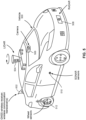
- FIG. 5 is a perspective view of such an vehicle 500 which includes an instance of INS 330 (not shown), which may be an instance of 350 as described herein.
- Vehicle 500 may include one or more cameras such as rear view mirror-mounted camera 506, front fender-mounted camera (not shown), side mirror-mounted camera (not shown) and a rear camera (not shown, but typically on the trunk, hatch or rear bumper).
- Vehicle 500 may also have lidar 504, for detecting objects and measuring distances to those objects; lidar 504 is often roof-mounted, however, if there are multiple lidar units 504, they may be oriented around the front, rear and sides of the vehicle.
- Vehicle 500 may have other various location-related systems such as a GNSS receiver (typically located in the shark fin unit on the rear of the roof, as indicated), various wireless communication interface (such as WAN, Wireless Local Area Network (WLAN), vehicle-to-everything (V2X); typically, but not necessarily, located in the shark fin on top of the vehicle), radar 508 (typically in the front bumper), and sonar 510 (typically located on both sides of the vehicle, if present).
- Various wheel sensors 512 e.g., wheel tick sensors
- drive train sensors may also be present, such as tire pressure sensors, accelerometers, gyros, and wheel rotation detection and/or counters.
- distance measurements and relative locations determined via various sensors may be combined with automotive size and shape information and information regarding the location of the sensor to determine distances and relative locations between the surfaces of different vehicles, such that a distance or vector from a sensor to another vehicle or between two different sensors (such as two GNSS receivers) is incrementally increased to account for the position of the sensor on each vehicle.
- a distance or vector from a sensor to another vehicle or between two different sensors such as two GNSS receivers
- FIG. 5 is intended to provide exemplary locations of various sensors in an embodiment of a vehicle comprising an instance of apparatus 310 (e.g., an instance of apparatus 340).
- FIG. 6 illustrates an example computer system 600 that may be utilized with and/or incorporate one or more electronic components of apparatus 310 and/or 340 (e.g., INS 330 (or 350), processor 320).
- computer system 600 is deployed in a vehicle (e.g., vehicle 500).
- vehicle 500 e.g., vehicle 500.
- FIG. 6 is meant only to provide a generalized illustration of various components, any or all of which may be utilized as appropriate. FIG. 6 , therefore, broadly illustrates how individual system elements may be implemented in a relatively separated or relatively more integrated manner.
- the computer system 600 may comprise hardware elements that can be communicatively coupled via a bus 605 (or other wired and/or wireless communication infrastructure, as appropriate).
- the hardware elements may include one or more processors 610, which can include without limitation one or more general-purpose processors, one or more special-purpose processors such as digital signal processor (DSP), graphics acceleration processors, application specific integrated circuits (ASICs), and/or the like.
- DSP digital signal processor
- ASICs application specific integrated circuits
- the processor(s) 610 may perform vehicular navigation processing including, for example, estimating position, velocity, and/or attitude.
- Processor 320 may be implemented in whole or in part within processor(s) 610.
- the computer system 600 may include one or more input devices 615, which can include without limitation a touch screen, a keyboard, a touch pad, a camera, a microphone, and/or other user input devices, map data (e.g., map data 619), and/or the like; and one or more output devices 627, which can include without limitation a display device, speakers, and/or the like.
- input devices 615 can include without limitation a touch screen, a keyboard, a touch pad, a camera, a microphone, and/or other user input devices, map data (e.g., map data 619), and/or the like
- output devices 627 which can include without limitation a display device, speakers, and/or the like.
- the computer system 600 may further include a wireless communication interface 630, which may include without limitation, a network card, an infrared communication device, a wireless communication interface 633, and/or a chipset (such as a Bluetooth ® device, an Institute of Electrical and Electronics Engineers (IEEE) 802.11 device, or cellular communication facilities), and/or the like, which may enable the computer system 600 to communicate with external computer systems or electronic devices.
- the communication can be carried out via one or more wireless communication antenna(s) (not shown) that send and/or receive wireless signals.
- the input devices 615 may further include one or more sensors.
- sensors may comprise, without limitation, one or more instances of: an INS 616 (e.g., INS 330 and/or INS 350 (including, e.g., an accelerometer, a gyroscope, and/or an IMU (e.g., IMU 360))), a radar 608 (e.g., radar 508), a camera 606 (e.g., camera 506), a magnetometer, a lidar 604 (e.g., lidar unit 504), an altimeter, a microphone, an ultrasonic sensor, a light sensor, a wheel sensor 612 (e.g., wheel sensor 512), and the like, some of which may be used to complement and/or facilitate the navigation-related processing described herein.
- an INS 616 e.g., INS 330 and/or INS 350 (including, e.g., an accelerometer, a gyroscope, and/or an I
- the computer system 600 may further include a GNSS receiver 602 (e.g., included as part of receiver 502 of FIG. 5 ) operable to receive signals from one or more GNSS satellites using an antenna.
- the signals can be utilized to complement and/or incorporate the techniques described herein (e.g., to correct INS states, such as position states, velocity states, and/or attitude states).
- the GNSS signals may be used to determine a geographical location of the computer system 600, e.g., for use in vehicle navigation.
- the computer system 600 may further include and/or be in communication with a memory 635 (e.g., short-term working memory) and one or more storage devices 625 (e.g., long-term data storage).
- the memory 635 and/or one or more storage devices 625 can include, without limitation, local and/or network accessible storage, a disk drive, a drive array, an optical storage device, a solid-state storage device, such as a random access memory (“RAM”), and/or a read-only memory (“ROM”), which can be programmable, flash-updateable, and/or the like.
- RAM random access memory
- ROM read-only memory
- Such storage devices may be configured to implement any appropriate data stores, including without limitation, various file systems, database structures, and/or the like.
- memory 635 may store a codebook comprising parameters for transmit waveforms.
- the memory 635 may comprise a non-transitory computer-readable medium storing instructions executable by one or more processors of computer system 600 (e.g., processors 610). Such instructions may be stored as program code, e.g., an operating system 640, device drivers, executable libraries, or other application programs 645. The instructions stored in memory 635 may be configured to cause the processor(s) to perform the radar-related processing described herein.
- program code e.g., an operating system 640, device drivers, executable libraries, or other application programs 645.
- the instructions stored in memory 635 may be configured to cause the processor(s) to perform the radar-related processing described herein.
- one or more procedures described with respect to the method 200 of FIG. 2A discussed above may be implemented as code and/or instructions executable by processor(s) 610.
- code and/or instructions can be used to configure and/or adapt a general purpose computer (or other computing device) to perform one or more operations in accordance with the techniques described herein.
- the term “signal” is used herein to indicate any of its ordinary meanings, including a state of a memory location (or set of memory locations) as expressed on a wire, bus, or other transmission medium.
- the term “generating” is used herein to indicate any of its ordinary meanings, such as computing or otherwise producing.
- the term “calculating” is used herein to indicate any of its ordinary meanings, such as computing, evaluating, estimating, and/or selecting from a plurality of values.
- the term "obtaining” is used to indicate any of its ordinary meanings, such as calculating, deriving, receiving (e.g., from an external device), and/or retrieving (e.g., from an array of storage elements).
- the term “selecting” is used to indicate any of its ordinary meanings, such as identifying, indicating, applying, and/or using at least one, and fewer than all, of a set of two or more.
- the term “determining” is used to indicate any of its ordinary meanings, such as deciding, establishing, concluding, calculating, selecting, and/or evaluating.
- the term "in response to” is used to indicate any of its ordinary meanings, including “in response to at least.” Unless otherwise indicated, the terms “at least one of A, B, and C,” “one or more of A, B, and C,” “at least one among A, B, and C,” and “one or more among A, B, and C” indicate “A and/or B and/or C.” Unless otherwise indicated, the terms “each of A, B, and C” and “each among A, B, and C” indicate “A and B and C.”
- any disclosure of an operation of an apparatus having a particular feature is also expressly intended to disclose a method having an analogous feature (and vice versa), and any disclosure of an operation of an apparatus according to a particular configuration is also expressly intended to disclose a method according to an analogous configuration (and vice versa).
- configuration may be used in reference to a method, apparatus, and/or system as indicated by its particular context.
- method means, “process,” “procedure,” and “technique” are used generically and interchangeably unless otherwise indicated by the particular context.
- a “task” having multiple subtasks is also a method.
- the terms “apparatus” and “device” are also used generically and interchangeably unless otherwise indicated by the particular context.
- an ordinal term e.g., “first,” “second,” “third,” etc.
- an ordinal term used to modify a claim element does not by itself indicate any priority or order of the claim element with respect to another, but rather merely distinguishes the claim element from another claim element having a same name (but for use of the ordinal term).
- each of the terms “plurality” and “set” is used herein to indicate an integer quantity that is greater than one.
- an implementation of an apparatus or system as disclosed herein may be embodied in any combination of hardware with software and/or with firmware that is deemed suitable for the intended application.
- such elements may be fabricated as electronic and/or optical devices residing, for example, on the same chip or among two or more chips in a chipset.
- One example of such a device is a fixed or programmable array of logic elements, such as transistors or logic gates, and any of these elements may be implemented as one or more such arrays. Any two or more, or even all, of these elements may be implemented within the same array or arrays.
- Such an array or arrays may be implemented within one or more chips (for example, within a chipset including two or more chips).
- a processor or other means for processing as disclosed herein may be fabricated as one or more electronic and/or optical devices residing, for example, on the same chip or among two or more chips in a chipset.
- One example of such a device is a fixed or programmable array of logic elements, such as transistors or logic gates, and any of these elements may be implemented as one or more such arrays.
- Such an array or arrays may be implemented within one or more chips (for example, within a chipset including two or more chips).
- arrays include fixed or programmable arrays of logic elements, such as microprocessors, embedded processors, intellectual property (IP) cores, DSPs (digital signal processors), FPGAs (field-programmable gate arrays), ASSPs (application-specific standard products), and ASICs (application-specific integrated circuits).
- IP intellectual property
- DSPs digital signal processors
- FPGAs field-programmable gate arrays
- ASSPs application-specific standard products
- ASICs application-specific integrated circuits
- a processor or other means for processing as disclosed herein may also be embodied as one or more computers (e.g., machines including one or more arrays programmed to execute one or more sets or sequences of instructions) or other processors.
- a processor as described herein can be used to perform operations or execute other sets of instructions that are not directly related to a procedure of an implementation of method 200 (or another method as disclosed with reference to operation of an apparatus or system described herein), such as a operation relating to another operation of a device or system in which the processor is embedded. It is also possible for part of a method as disclosed herein to be performed under the control of one or more other processors.
- an array of logic elements e.g., logic gates
- an array of logic elements is configured to perform one, more than one, or even all of the various operations of the method.
- One or more (possibly all) of the operations may also be implemented as code (e.g., one or more sets of instructions), embodied in a computer program product (e.g., one or more data storage media such as disks, flash or other nonvolatile memory cards, semiconductor memory chips, etc.), that is readable and/or executable by a machine (e.g., a computer) including an array of logic elements (e.g., a processor, microprocessor, microcontroller, or other finite state machine).
- code e.g., one or more sets of instructions
- a computer program product e.g., one or more data storage media such as disks, flash or other nonvolatile memory cards, semiconductor memory chips, etc.
- a machine e.g., a computer
- an array of logic elements e.g., a processor, microprocessor, microcontroller, or other finite state machine.
- the operations of an implementation of a method as disclosed herein may also be performed by more than one such array
- the operations described herein may be implemented in hardware, software, firmware, or any combination thereof. If implemented in software, such operations may be stored on or transmitted over a computer-readable medium as one or more instructions or code.
- computer-readable media includes both computer-readable storage media and communication (e.g., transmission) media.
- computer-readable storage media can comprise an array of storage elements, such as semiconductor memory (which may include without limitation dynamic or static RAM, ROM, electrically Erasable Programmable Read-Only Memory (EEPROM), and/or flash RAM), or ferroelectric, magnetoresistive, ovonic, polymeric, or phase-change memory; Compact Disc-Read Only Memory (CD-ROM) or other optical disk storage; and/or magnetic disk storage or other magnetic storage devices.
- semiconductor memory which may include without limitation dynamic or static RAM, ROM, electrically Erasable Programmable Read-Only Memory (EEPROM), and/or flash RAM
- ferroelectric, magnetoresistive, ovonic, polymeric, or phase-change memory such as Compact Disc-Read Only Memory (CD-ROM) or other optical disk storage
- CD-ROM Compact Disc-Read Only Memory
- Communication media can comprise any medium that can be used to carry desired program code in the form of instructions or data structures and that can be accessed by a computer, including any medium that facilitates transfer of a computer program from one place to another. Also, any connection is properly termed a computer-readable medium. For example, if the software is transmitted from a website, server, or other remote source using a coaxial cable, fiber optic cable, twisted pair, digital subscriber line (DSL), or wireless technology such as infrared, radio, and/or microwave, then the coaxial cable, fiber optic cable, twisted pair, DSL, or wireless technology such as infrared, radio, and/or microwave are included in the definition of medium.
- DSL digital subscriber line
- Disk and disc includes compact disc (CD), laser disc, optical disc, digital versatile disc (DVD), floppy disk and Blu-ray Disc TM (Blu-Ray Disc Association, Universal City, Calif.), where disks usually reproduce data magnetically, while discs reproduce data optically with lasers. Combinations of the above should also be included within the scope of computer-readable media.
- a non-transitory computer-readable storage medium comprises code which, when executed by at least one processor, causes the at least one processor to perform a method of vehicular navigation as described herein.
Landscapes
- Engineering & Computer Science (AREA)
- Radar, Positioning & Navigation (AREA)
- Remote Sensing (AREA)
- Physics & Mathematics (AREA)
- General Physics & Mathematics (AREA)
- Computer Networks & Wireless Communication (AREA)
- Automation & Control Theory (AREA)
- Signal Processing (AREA)
- Mathematical Physics (AREA)
- Transportation (AREA)
- Mechanical Engineering (AREA)
- Navigation (AREA)
Claims (10)
- Procédé (200) de navigation de véhicule, le procédé comprenant :la détermination (210) d'une première assiette d'un véhicule par rapport à un référentiel à une première époque ;sur la base de données de mesure provenant d'un système de navigation inertielle, INS, du véhicule, la détermination (220) d'une assiette de l'INS à une seconde époque postérieure à la première époque ;sur la base de l'assiette déterminée de l'INS à la seconde époque, la détermination (230) d'une seconde assiette du véhicule à la seconde époque ;lorsqu'il est déterminé qu'une variation absolue de l'angle de lacet du véhicule entre la première époque et la seconde époque est inférieure à un seuil prédéterminé :l'application (240) d'une contrainte à la seconde assiette déterminée du véhicule pour produire une seconde assiette actualisée du véhicule, l'application de la contrainte comprenant le réglage d'un angle de roulis de la seconde assiette déterminée du véhicule à une valeur égale à un angle de roulis de la première assiette déterminée du véhicule ; etsur la base de la seconde assiette actualisée du véhicule, la détermination (250) d'une assiette actualisée de l'INS,dans lequel les données de mesure indiquent une vitesse de rotation autour d'au moins un axe d'un gyroscope de l'INS.
- Procédé selon la revendication 1, dans lequel la détermination de la première assiette du véhicule est basée, au moins en partie, sur :une assiette de l'INS à la première époque par rapport au référentiel, ouune orientation d'un ossature de caisse de l'INS à la première époque par rapport à un ossature de caisse du véhicule, ouune combinaison de celles-ci.
- Procédé selon la revendication 1, dans lequel l'assiette de l'INS à la seconde époque est une assiette par rapport au référentiel.
- Procédé selon la revendication 1, dans lequel l'assiette de l'INS à la seconde époque est basée sur une assiette de l'INS à la première époque.
- Procédé selon la revendication 1, le procédé étant mis en œuvre durant une période de navigation à l'estime du véhicule.
- Procédé selon la revendication 1, comprenant en outre la fourniture de l'assiette actualisée de l'INS.
- Procédé selon la revendication 6, dans lequel la fourniture de l'assiette actualisée de l'INS comprend la fourniture de données indicatives de l'assiette actualisée de l'INS à une application logicielle, un système d'exploitation, une interface utilisateur, un système de véhicule ou un dispositif à distance, ou une combinaison de ceux-ci.
- Dispositif (600) de navigation de véhicule, le dispositif comprenant :un système de navigation inertielle (616), INS ;une mémoire (625) ; etun ou plusieurs processeurs (610) couplés pour communiquer avec l'INS et la mémoire, dans lesquels les un ou plusieurs processeurs sont configurés pour :déterminer une première assiette d'un véhicule par rapport à un référentiel à une première époque ;sur la base de données de mesure provenant de l'INS, déterminer une assiette de l'INS à une seconde époque postérieure à la première époque,sur la base de l'assiette déterminée de l'INS à la seconde époque, déterminer une seconde assiette du véhicule à la seconde époque ;lorsqu'il est déterminé qu'une variation absolue de l'angle de lacet du véhicule entre la première époque et la seconde époque est inférieure à un seuil prédéterminé :appliquer une contrainte à la seconde assiette déterminée du véhicule pour produire une seconde assiette actualisée du véhicule, l'application de la contrainte comprenant le réglage d'un angle de roulis de la seconde assiette déterminée du véhicule à une valeur égale à un angle de roulis de la première assiette déterminée du véhicule ; etsur la base de la seconde assiette actualisée du véhicule, déterminer une assiette actualisée de l'INS,dans lequel l'INS est configuré pour inclure, dans les données de mesure, une vitesse de rotation autour d'au moins un axe d'un gyroscope de l'INS.
- Dispositif selon la revendication 8, dans lequel les un ou plusieurs processeurs sont configurés en outre pour réaliser le procédé selon l'une quelconque des revendications 2 à 7.
- Support non transitoire lisible par ordinateur stockant des instructions pour une navigation de véhicule, les instructions comprenant un code pour réaliser le procédé selon l'une quelconque des revendications 1 à 7.
Applications Claiming Priority (3)
| Application Number | Priority Date | Filing Date | Title |
|---|---|---|---|
| US202063063834P | 2020-08-10 | 2020-08-10 | |
| US17/397,783 US12535323B2 (en) | 2020-08-10 | 2021-08-09 | Updating vehicle attitude for extended dead reckoning accuracy |
| PCT/US2021/045364 WO2022035837A1 (fr) | 2020-08-10 | 2021-08-10 | Précision de navigation à l'estime étendue |
Publications (3)
| Publication Number | Publication Date |
|---|---|
| EP4193122A1 EP4193122A1 (fr) | 2023-06-14 |
| EP4193122C0 EP4193122C0 (fr) | 2025-04-23 |
| EP4193122B1 true EP4193122B1 (fr) | 2025-04-23 |
Family
ID=80114887
Family Applications (1)
| Application Number | Title | Priority Date | Filing Date |
|---|---|---|---|
| EP21762578.9A Active EP4193122B1 (fr) | 2020-08-10 | 2021-08-10 | Précision de navigation à l'estime étendue |
Country Status (8)
| Country | Link |
|---|---|
| US (1) | US12535323B2 (fr) |
| EP (1) | EP4193122B1 (fr) |
| KR (1) | KR20230048324A (fr) |
| CN (1) | CN116056966A (fr) |
| BR (1) | BR112023001879A2 (fr) |
| PH (1) | PH12022553457A1 (fr) |
| TW (1) | TWI893187B (fr) |
| WO (1) | WO2022035837A1 (fr) |
Families Citing this family (5)
| Publication number | Priority date | Publication date | Assignee | Title |
|---|---|---|---|---|
| US10753752B2 (en) * | 2018-07-26 | 2020-08-25 | Trimble Inc. | Vehicle manual guidance systems with steering wheel angle sensors and road wheel angle sensors |
| CN114572231B (zh) * | 2022-03-14 | 2024-09-17 | 中国第一汽车股份有限公司 | 紧急避障工况下车辆漂移运动的质心侧偏角规划方法、装置、车辆和计算机可读存储介质 |
| US12429609B2 (en) * | 2022-09-09 | 2025-09-30 | Rivian Ip Holdings, Llc | Vehicle state estimation system and method |
| CN115932918A (zh) * | 2023-01-05 | 2023-04-07 | 广州小鹏自动驾驶科技有限公司 | 车辆定位方法、装置、车辆及存储介质 |
| CN119687960B (zh) * | 2024-12-20 | 2025-11-14 | 武汉大学 | 一种使用GNSS辅助的基于里程计的LiDAR-IMU标定方法及系统 |
Family Cites Families (13)
| Publication number | Priority date | Publication date | Assignee | Title |
|---|---|---|---|---|
| JP5091047B2 (ja) * | 2008-08-12 | 2012-12-05 | 株式会社豊田中央研究所 | 車両姿勢角推定装置及びセンサドリフト推定装置 |
| KR101160630B1 (ko) * | 2010-03-26 | 2012-06-28 | 위드로봇 주식회사 | 주행 모드 판별법, 상기 주행 모드 판별을 이용한 항법 시스템 및 그 제공방법 |
| TWI475190B (zh) | 2011-04-29 | 2015-03-01 | Kuo Ching Chiang | 利於慣性導航之裝置及其導航方法 |
| TWI522258B (zh) | 2013-07-08 | 2016-02-21 | Kang Li | Based on electronic map, global navigation satellite system and vehicle motion detection technology Lane identification method |
| US10222208B2 (en) * | 2013-12-27 | 2019-03-05 | Intel Corporation | Apparatus, system and method of estimating an orientation of a mobile device |
| US10288446B2 (en) * | 2016-02-05 | 2019-05-14 | Logitech Europe S.A. | System and method for movement triggering a head-mounted electronic device while inclined |
| CN106405592B (zh) * | 2016-12-09 | 2019-05-17 | 惠州市组合科技有限公司 | 车载北斗载波相位周跳检测与修复方法及系统 |
| US10533856B2 (en) * | 2017-04-05 | 2020-01-14 | Novatel Inc. | Navigation system utilizing yaw rate constraint during inertial dead reckoning |
| FR3095041B1 (fr) * | 2019-04-15 | 2021-03-19 | Commissariat Energie Atomique | Procede de determination de la position et de l'orientation d'un vehicule |
| US20210123754A1 (en) * | 2019-10-25 | 2021-04-29 | GM Global Technology Operations LLC | Method for unsupervised automatic alignment of vehicle sensors |
| CN110879066A (zh) * | 2019-12-26 | 2020-03-13 | 河北美泰电子科技有限公司 | 一种姿态解算算法、装置及车载惯性导航系统 |
| US10783784B1 (en) * | 2020-03-31 | 2020-09-22 | Lyft, Inc. | Free lock detection of a micromobility transit vehicle systems and methods |
| US11518464B2 (en) * | 2020-05-26 | 2022-12-06 | Here Global B.V. | Method, apparatus, and system for providing automatic alerts for transportation maneuver events |
-
2021
- 2021-08-09 US US17/397,783 patent/US12535323B2/en active Active
- 2021-08-10 CN CN202180057003.7A patent/CN116056966A/zh active Pending
- 2021-08-10 KR KR1020237004150A patent/KR20230048324A/ko active Pending
- 2021-08-10 EP EP21762578.9A patent/EP4193122B1/fr active Active
- 2021-08-10 TW TW110129522A patent/TWI893187B/zh active
- 2021-08-10 WO PCT/US2021/045364 patent/WO2022035837A1/fr not_active Ceased
- 2021-08-10 PH PH1/2022/553457A patent/PH12022553457A1/en unknown
- 2021-08-10 BR BR112023001879A patent/BR112023001879A2/pt unknown
Also Published As
| Publication number | Publication date |
|---|---|
| EP4193122A1 (fr) | 2023-06-14 |
| EP4193122C0 (fr) | 2025-04-23 |
| WO2022035837A1 (fr) | 2022-02-17 |
| US20220042802A1 (en) | 2022-02-10 |
| TW202212777A (zh) | 2022-04-01 |
| CN116056966A (zh) | 2023-05-02 |
| PH12022553457A1 (en) | 2024-03-04 |
| KR20230048324A (ko) | 2023-04-11 |
| US12535323B2 (en) | 2026-01-27 |
| TWI893187B (zh) | 2025-08-11 |
| BR112023001879A2 (pt) | 2023-03-07 |
Similar Documents
| Publication | Publication Date | Title |
|---|---|---|
| EP4193122B1 (fr) | Précision de navigation à l'estime étendue | |
| US12405112B2 (en) | Inertial navigation system capable of dead reckoning in vehicles | |
| US9921065B2 (en) | Unit and method for improving positioning accuracy | |
| US10788830B2 (en) | Systems and methods for determining a vehicle position | |
| JP4964047B2 (ja) | 位置検出装置及び位置検出方法 | |
| CN102648394B (zh) | 惯性测量单元(imu)的空间对准确定 | |
| CN111562603B (zh) | 基于航位推算的导航定位方法、设备及存储介质 | |
| US20150247728A1 (en) | Systems for navigating using corrected yaw bias values | |
| CN106291647B (zh) | 导航定位方法及装置 | |
| JP2025542376A (ja) | レーダー及びモーションセンサを使用したマップ構築のための方法及びシステム | |
| JP2016218015A (ja) | 車載センサ補正装置、自己位置推定装置、プログラム | |
| US20230051377A1 (en) | Mobility movemennt information acquiring method and mobility movement information acquiring apparatus | |
| KR101639152B1 (ko) | 도로 구배를 이용한 차량 위치 추정 방법 및 장치 | |
| JP6248559B2 (ja) | 車両用走行軌跡算出装置 | |
| JP2023548513A (ja) | 多義性の解明によって少なくとも1つのgnss衛星信号を評価する方法 | |
| JP7318995B1 (ja) | 移動体挙動情報取得方法、移動体挙動情報取得装置及びプログラム | |
| EP4354182A1 (fr) | Post-traitement de données de système mondial de navigation par satellite (gnss) | |
| JP5062141B2 (ja) | 移動体用測位装置 | |
| CN111002991B (zh) | 一种车载导航信息处理的方法、装置及计算机存储介质 | |
| Han et al. | Development of GNSS/WSS/YRS integration algorithm for land vehicle positioning | |
| JP2015135305A (ja) | ナビゲーション装置、測位装置 | |
| JP2023144961A (ja) | 評価方法、及び評価システム | |
| CN119666004A (zh) | 使用众包技术的基于高精度地图的导航方法和导航系统 | |
| CN120322765A (zh) | 用于确定道路曲率的方法和装置 | |
| CN120702486A (zh) | 一种载具组合导航方法、装置、设备及介质 |
Legal Events
| Date | Code | Title | Description |
|---|---|---|---|
| STAA | Information on the status of an ep patent application or granted ep patent |
Free format text: STATUS: UNKNOWN |
|
| STAA | Information on the status of an ep patent application or granted ep patent |
Free format text: STATUS: THE INTERNATIONAL PUBLICATION HAS BEEN MADE |
|
| PUAI | Public reference made under article 153(3) epc to a published international application that has entered the european phase |
Free format text: ORIGINAL CODE: 0009012 |
|
| STAA | Information on the status of an ep patent application or granted ep patent |
Free format text: STATUS: REQUEST FOR EXAMINATION WAS MADE |
|
| 17P | Request for examination filed |
Effective date: 20221222 |
|
| AK | Designated contracting states |
Kind code of ref document: A1 Designated state(s): AL AT BE BG CH CY CZ DE DK EE ES FI FR GB GR HR HU IE IS IT LI LT LU LV MC MK MT NL NO PL PT RO RS SE SI SK SM TR |
|
| DAV | Request for validation of the european patent (deleted) | ||
| DAX | Request for extension of the european patent (deleted) | ||
| STAA | Information on the status of an ep patent application or granted ep patent |
Free format text: STATUS: EXAMINATION IS IN PROGRESS |
|
| 17Q | First examination report despatched |
Effective date: 20240419 |
|
| RIC1 | Information provided on ipc code assigned before grant |
Ipc: B60W 40/114 20120101ALI20240911BHEP Ipc: B60W 40/112 20120101ALI20240911BHEP Ipc: G01S 19/49 20100101ALI20240911BHEP Ipc: G01C 21/16 20060101AFI20240911BHEP |
|
| GRAP | Despatch of communication of intention to grant a patent |
Free format text: ORIGINAL CODE: EPIDOSNIGR1 |
|
| STAA | Information on the status of an ep patent application or granted ep patent |
Free format text: STATUS: GRANT OF PATENT IS INTENDED |
|
| RIN1 | Information on inventor provided before grant (corrected) |
Inventor name: MORRISON, WILLIAM Inventor name: ZHENG, BO Inventor name: LAKHZOURI, ABDELMONAEM Inventor name: SAINI, VINOD KUMAR |
|
| INTG | Intention to grant announced |
Effective date: 20241127 |
|
| GRAS | Grant fee paid |
Free format text: ORIGINAL CODE: EPIDOSNIGR3 |
|
| GRAA | (expected) grant |
Free format text: ORIGINAL CODE: 0009210 |
|
| STAA | Information on the status of an ep patent application or granted ep patent |
Free format text: STATUS: THE PATENT HAS BEEN GRANTED |
|
| AK | Designated contracting states |
Kind code of ref document: B1 Designated state(s): AL AT BE BG CH CY CZ DE DK EE ES FI FR GB GR HR HU IE IS IT LI LT LU LV MC MK MT NL NO PL PT RO RS SE SI SK SM TR |
|
| REG | Reference to a national code |
Ref country code: GB Ref legal event code: FG4D |
|
| REG | Reference to a national code |
Ref country code: CH Ref legal event code: EP |
|
| REG | Reference to a national code |
Ref country code: DE Ref legal event code: R096 Ref document number: 602021029647 Country of ref document: DE |
|
| REG | Reference to a national code |
Ref country code: IE Ref legal event code: FG4D |
|
| U01 | Request for unitary effect filed |
Effective date: 20250514 |
|
| U07 | Unitary effect registered |
Designated state(s): AT BE BG DE DK EE FI FR IT LT LU LV MT NL PT RO SE SI Effective date: 20250519 |
|
| U20 | Renewal fee for the european patent with unitary effect paid |
Year of fee payment: 5 Effective date: 20250710 |
|
| PG25 | Lapsed in a contracting state [announced via postgrant information from national office to epo] |
Ref country code: ES Free format text: LAPSE BECAUSE OF FAILURE TO SUBMIT A TRANSLATION OF THE DESCRIPTION OR TO PAY THE FEE WITHIN THE PRESCRIBED TIME-LIMIT Effective date: 20250423 |
|
| PG25 | Lapsed in a contracting state [announced via postgrant information from national office to epo] |
Ref country code: NO Free format text: LAPSE BECAUSE OF FAILURE TO SUBMIT A TRANSLATION OF THE DESCRIPTION OR TO PAY THE FEE WITHIN THE PRESCRIBED TIME-LIMIT Effective date: 20250723 Ref country code: GR Free format text: LAPSE BECAUSE OF FAILURE TO SUBMIT A TRANSLATION OF THE DESCRIPTION OR TO PAY THE FEE WITHIN THE PRESCRIBED TIME-LIMIT Effective date: 20250724 |
|
| PG25 | Lapsed in a contracting state [announced via postgrant information from national office to epo] |
Ref country code: PL Free format text: LAPSE BECAUSE OF FAILURE TO SUBMIT A TRANSLATION OF THE DESCRIPTION OR TO PAY THE FEE WITHIN THE PRESCRIBED TIME-LIMIT Effective date: 20250423 |
|
| PGFP | Annual fee paid to national office [announced via postgrant information from national office to epo] |
Ref country code: GB Payment date: 20250710 Year of fee payment: 5 |
|
| PG25 | Lapsed in a contracting state [announced via postgrant information from national office to epo] |
Ref country code: HR Free format text: LAPSE BECAUSE OF FAILURE TO SUBMIT A TRANSLATION OF THE DESCRIPTION OR TO PAY THE FEE WITHIN THE PRESCRIBED TIME-LIMIT Effective date: 20250423 |
|
| PG25 | Lapsed in a contracting state [announced via postgrant information from national office to epo] |
Ref country code: RS Free format text: LAPSE BECAUSE OF FAILURE TO SUBMIT A TRANSLATION OF THE DESCRIPTION OR TO PAY THE FEE WITHIN THE PRESCRIBED TIME-LIMIT Effective date: 20250723 |
|
| PGFP | Annual fee paid to national office [announced via postgrant information from national office to epo] |
Ref country code: IE Payment date: 20250709 Year of fee payment: 5 |
|
| PG25 | Lapsed in a contracting state [announced via postgrant information from national office to epo] |
Ref country code: IS Free format text: LAPSE BECAUSE OF FAILURE TO SUBMIT A TRANSLATION OF THE DESCRIPTION OR TO PAY THE FEE WITHIN THE PRESCRIBED TIME-LIMIT Effective date: 20250823 |
|
| PG25 | Lapsed in a contracting state [announced via postgrant information from national office to epo] |
Ref country code: SM Free format text: LAPSE BECAUSE OF FAILURE TO SUBMIT A TRANSLATION OF THE DESCRIPTION OR TO PAY THE FEE WITHIN THE PRESCRIBED TIME-LIMIT Effective date: 20250423 |
|
| PG25 | Lapsed in a contracting state [announced via postgrant information from national office to epo] |
Ref country code: CZ Free format text: LAPSE BECAUSE OF FAILURE TO SUBMIT A TRANSLATION OF THE DESCRIPTION OR TO PAY THE FEE WITHIN THE PRESCRIBED TIME-LIMIT Effective date: 20250423 |
|
| PG25 | Lapsed in a contracting state [announced via postgrant information from national office to epo] |
Ref country code: SK Free format text: LAPSE BECAUSE OF FAILURE TO SUBMIT A TRANSLATION OF THE DESCRIPTION OR TO PAY THE FEE WITHIN THE PRESCRIBED TIME-LIMIT Effective date: 20250423 |
|
| PLBE | No opposition filed within time limit |
Free format text: ORIGINAL CODE: 0009261 |
|
| STAA | Information on the status of an ep patent application or granted ep patent |
Free format text: STATUS: NO OPPOSITION FILED WITHIN TIME LIMIT |
|
| REG | Reference to a national code |
Ref country code: CH Ref legal event code: L10 Free format text: ST27 STATUS EVENT CODE: U-0-0-L10-L00 (AS PROVIDED BY THE NATIONAL OFFICE) Effective date: 20260304 |
|
| REG | Reference to a national code |
Ref country code: CH Ref legal event code: H13 Free format text: ST27 STATUS EVENT CODE: U-0-0-H10-H13 (AS PROVIDED BY THE NATIONAL OFFICE) Effective date: 20260324 |
|
| PG25 | Lapsed in a contracting state [announced via postgrant information from national office to epo] |
Ref country code: MC Free format text: LAPSE BECAUSE OF FAILURE TO SUBMIT A TRANSLATION OF THE DESCRIPTION OR TO PAY THE FEE WITHIN THE PRESCRIBED TIME-LIMIT Effective date: 20250423 |
|
| 26N | No opposition filed |
Effective date: 20260126 |