EP4193905A1 - Scanner intra-oral, système de balayage intra-oral, procédé permettant d'effectuer des balayages intra-oraux et produit-programme informatique - Google Patents
Scanner intra-oral, système de balayage intra-oral, procédé permettant d'effectuer des balayages intra-oraux et produit-programme informatique Download PDFInfo
- Publication number
- EP4193905A1 EP4193905A1 EP21212940.7A EP21212940A EP4193905A1 EP 4193905 A1 EP4193905 A1 EP 4193905A1 EP 21212940 A EP21212940 A EP 21212940A EP 4193905 A1 EP4193905 A1 EP 4193905A1
- Authority
- EP
- European Patent Office
- Prior art keywords
- intraoral
- microlenses
- intraoral scanner
- dentition
- cameras
- Prior art date
- Legal status (The legal status is an assumption and is not a legal conclusion. Google has not performed a legal analysis and makes no representation as to the accuracy of the status listed.)
- Pending
Links
Images




Classifications
-
- A—HUMAN NECESSITIES
- A61—MEDICAL OR VETERINARY SCIENCE; HYGIENE
- A61C—DENTISTRY; APPARATUS OR METHODS FOR ORAL OR DENTAL HYGIENE
- A61C19/00—Dental auxiliary appliances
- A61C19/04—Measuring instruments specially adapted for dentistry
-
- A—HUMAN NECESSITIES
- A61—MEDICAL OR VETERINARY SCIENCE; HYGIENE
- A61B—DIAGNOSIS; SURGERY; IDENTIFICATION
- A61B1/00—Instruments for performing medical examinations of the interior of cavities or tubes of the body by visual or photographical inspection, e.g. endoscopes; Illuminating arrangements therefor
- A61B1/06—Instruments for performing medical examinations of the interior of cavities or tubes of the body by visual or photographical inspection, e.g. endoscopes; Illuminating arrangements therefor with illuminating arrangements
- A61B1/0605—Instruments for performing medical examinations of the interior of cavities or tubes of the body by visual or photographical inspection, e.g. endoscopes; Illuminating arrangements therefor with illuminating arrangements for spatially modulated illumination
-
- A—HUMAN NECESSITIES
- A61—MEDICAL OR VETERINARY SCIENCE; HYGIENE
- A61B—DIAGNOSIS; SURGERY; IDENTIFICATION
- A61B1/00—Instruments for performing medical examinations of the interior of cavities or tubes of the body by visual or photographical inspection, e.g. endoscopes; Illuminating arrangements therefor
- A61B1/00064—Constructional details of the endoscope body
- A61B1/00071—Insertion part of the endoscope body
- A61B1/0008—Insertion part of the endoscope body characterised by distal tip features
- A61B1/00096—Optical elements
-
- A—HUMAN NECESSITIES
- A61—MEDICAL OR VETERINARY SCIENCE; HYGIENE
- A61B—DIAGNOSIS; SURGERY; IDENTIFICATION
- A61B1/00—Instruments for performing medical examinations of the interior of cavities or tubes of the body by visual or photographical inspection, e.g. endoscopes; Illuminating arrangements therefor
- A61B1/00163—Optical arrangements
- A61B1/00172—Optical arrangements with means for scanning
-
- A—HUMAN NECESSITIES
- A61—MEDICAL OR VETERINARY SCIENCE; HYGIENE
- A61B—DIAGNOSIS; SURGERY; IDENTIFICATION
- A61B1/00—Instruments for performing medical examinations of the interior of cavities or tubes of the body by visual or photographical inspection, e.g. endoscopes; Illuminating arrangements therefor
- A61B1/24—Instruments for performing medical examinations of the interior of cavities or tubes of the body by visual or photographical inspection, e.g. endoscopes; Illuminating arrangements therefor for the mouth, i.e. stomatoscopes, e.g. with tongue depressors; Instruments for opening or keeping open the mouth
-
- A—HUMAN NECESSITIES
- A61—MEDICAL OR VETERINARY SCIENCE; HYGIENE
- A61B—DIAGNOSIS; SURGERY; IDENTIFICATION
- A61B5/00—Measuring for diagnostic purposes; Identification of persons
- A61B5/0059—Measuring for diagnostic purposes; Identification of persons using light, e.g. diagnosis by transillumination, diascopy, fluorescence
- A61B5/0082—Measuring for diagnostic purposes; Identification of persons using light, e.g. diagnosis by transillumination, diascopy, fluorescence adapted for particular medical purposes
- A61B5/0088—Measuring for diagnostic purposes; Identification of persons using light, e.g. diagnosis by transillumination, diascopy, fluorescence adapted for particular medical purposes for oral or dental tissue
-
- A—HUMAN NECESSITIES
- A61—MEDICAL OR VETERINARY SCIENCE; HYGIENE
- A61C—DENTISTRY; APPARATUS OR METHODS FOR ORAL OR DENTAL HYGIENE
- A61C13/00—Dental prostheses; Making same
- A61C13/34—Making or working of models, e.g. preliminary castings, trial dentures; Dowel pins [4]
-
- A—HUMAN NECESSITIES
- A61—MEDICAL OR VETERINARY SCIENCE; HYGIENE
- A61C—DENTISTRY; APPARATUS OR METHODS FOR ORAL OR DENTAL HYGIENE
- A61C9/00—Impression cups, i.e. impression trays; Impression methods
- A61C9/004—Means or methods for taking digitized impressions
- A61C9/0046—Data acquisition means or methods
- A61C9/0053—Optical means or methods, e.g. scanning the teeth by a laser or light beam
-
- A—HUMAN NECESSITIES
- A61—MEDICAL OR VETERINARY SCIENCE; HYGIENE
- A61C—DENTISTRY; APPARATUS OR METHODS FOR ORAL OR DENTAL HYGIENE
- A61C9/00—Impression cups, i.e. impression trays; Impression methods
- A61C9/004—Means or methods for taking digitized impressions
- A61C9/0046—Data acquisition means or methods
- A61C9/0053—Optical means or methods, e.g. scanning the teeth by a laser or light beam
- A61C9/006—Optical means or methods, e.g. scanning the teeth by a laser or light beam projecting one or more stripes or patterns on the teeth
-
- G—PHYSICS
- G06—COMPUTING OR CALCULATING; COUNTING
- G06F—ELECTRIC DIGITAL DATA PROCESSING
- G06F17/00—Digital computing or data processing equipment or methods, specially adapted for specific functions
-
- G—PHYSICS
- G06—COMPUTING OR CALCULATING; COUNTING
- G06T—IMAGE DATA PROCESSING OR GENERATION, IN GENERAL
- G06T17/00—Three-dimensional [3D] modelling for computer graphics
-
- G—PHYSICS
- G06—COMPUTING OR CALCULATING; COUNTING
- G06T—IMAGE DATA PROCESSING OR GENERATION, IN GENERAL
- G06T19/00—Manipulating three-dimensional [3D] models or images for computer graphics
- G06T19/20—Editing of three-dimensional [3D] images, e.g. changing shapes or colours, aligning objects or positioning parts
-
- G—PHYSICS
- G06—COMPUTING OR CALCULATING; COUNTING
- G06T—IMAGE DATA PROCESSING OR GENERATION, IN GENERAL
- G06T3/00—Geometric image transformations in the plane of the image
- G06T3/40—Scaling of whole images or parts thereof, e.g. expanding or contracting
-
- G—PHYSICS
- G06—COMPUTING OR CALCULATING; COUNTING
- G06T—IMAGE DATA PROCESSING OR GENERATION, IN GENERAL
- G06T7/00—Image analysis
-
- G—PHYSICS
- G06—COMPUTING OR CALCULATING; COUNTING
- G06T—IMAGE DATA PROCESSING OR GENERATION, IN GENERAL
- G06T2200/00—Indexing scheme for image data processing or generation, in general
- G06T2200/08—Indexing scheme for image data processing or generation, in general involving all processing steps from image acquisition to 3D model generation
-
- G—PHYSICS
- G06—COMPUTING OR CALCULATING; COUNTING
- G06T—IMAGE DATA PROCESSING OR GENERATION, IN GENERAL
- G06T2207/00—Indexing scheme for image analysis or image enhancement
- G06T2207/30—Subject of image; Context of image processing
- G06T2207/30004—Biomedical image processing
- G06T2207/30036—Dental; Teeth
-
- G—PHYSICS
- G06—COMPUTING OR CALCULATING; COUNTING
- G06T—IMAGE DATA PROCESSING OR GENERATION, IN GENERAL
- G06T2210/00—Indexing scheme for image generation or computer graphics
- G06T2210/41—Medical
Definitions
- the invention relates to an intraoral scanner comprising:
- the invention further relates to an intraoral scanning system, a method for performing intraoral scans and a computer program product.
- WO 2019/236934 A1 discloses an intraoral scanner, that uses an array of microlenses for generating a pattern, that is imaged on the dentition by some further optics.
- the intraoral scanning system is arranged for generating a three-dimensional model of the dentition by triangulation.
- a disadvantage of the known intraoral scanner is its complexity so that numerous components must be assembled for manufacturing the intraoral scanner.
- the present invention seeks to provide an intraoral scanner of reduced complexity and an associated intraoral scanning system, which is able to generate three-dimensional models of a dentition at least as precisely as conventional intraoral scanners.
- the invention further seeks to provide a corresponding method and a computer program product.
- the pattern is a non-periodic dot pattern generated by a two-dimensional array of microlenses arranged on a substrate in a non-periodic manner and this array of microlenses is the last beam shaping optical element before the object in the direction of the radiation.
- Such an irregular array of microlenses is particularly useful for determining the surfaces of tissue in the oral cavity since the radiation emitted by the radiation source is completely used for generating the dot pattern.
- the dots of the pattern are consequently highly visible in the images taken by the cameras. Due to the high density of microlenses the dot pattern can also be very dense so that the structure of the dentition can be resolved with high accuracy.
- the microlens array also provides a high depth sharpness due to the small lateral extension of the microlenses. Thus, no further beam shaping optics is needed between the microlens array and the object, so that the complexity of the intraoral scanner is considerably reduced compared to conventional intraoral scanners.
- mirrors or planar windows shall not be considered as beam-shaping optical elements.
- the rays of the beam arriving at the microlenses are generally not collimated.
- the working distance, at which the size of the dots is at a minimum, is consequently greater than the focal length of the microlenses, the working distance and the focal length each being measured in radiation direction from the base of the microlenses on the surface of the substrate.
- the microlenses are arranged in a honeycomb structure, the center of each microlens being shifted off-center from the center of the corresponding honeycomb cell by a randomly selected distance and direction. This allows to maximize the density of microlenses whose boundaries are nearly circularly shaped.
- the radiation source is generally a laser diode and the divergence of the beam emerging from the laser diode is homogenized by an optical element located between the laser diode and the array of microlenses.
- the cameras are generally oriented in the same direction, since the cameras can easily be mounted side by side on the same circuit board. If the cameras are oriented in the same direction, the depth resolution is also maximized.
- the cameras are disposed next to each other and the center of the array of microlenses is located at a distance from the baseline between the cameras, usually below the cameras.
- An intraoral scanning system for generating a three-dimensional model of a dentition using active stereo vision comprises an intraoral scanner as described above, wherein each camera generates a series of images patterns projected onto the dentition.
- the intraoral scanning system further comprises a data processing unit connected to the intraoral scanner for generating the three-dimensional model of the dentition based on disparity maps formed by means of a synchronized series of images generated by each camera.
- the data processing unit of the intraoral scanning system is particularly arranged for performing the following acts:
- a corresponding method for generating a three-dimensional model of a dentition based on active stereo vision may comprise the following acts:
- a computer program product contains program code for implementing the method when run on a data processing unit.
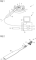
- FIG. 1 shows an intraoral scanning system 1 that can be used for generating a three-dimensional model of a dentition 2.
- the intra oral scanning system 1 comprises an intraoral scanner 3 extending along a longitudinal axis L.
- a projector 4 located within the scanner 3 emits radiation 5 and projects a dot pattern 6 onto the dentition 2.
- the dot pattern 6 is imaged by a first camera 7 and a second camera 8 in a synchronized manner.
- the operation of the projector 4, the first camera 7 and the second camera 8 may be controlled by a control unit 9 which may be located within a handle 10 of the scanner 3.
- the digital images generated by the first camera 7 and the second camera 8 are transferred to a data processing unit 11.
- the data processing unit 11 comprises a data bus 12, a processor 13 and storage means 14 for storing data such as the digital images and computer programs that might be used for processing the digital images as described herein.
- the data processing unit 11 may also be provided with the usual input means 15 such as a keyboard or a mouse and with the usual output means such as a display 16.
- Figure 2 is a perspective view of some inner components of the intraoral scanner 3.
- the projector 4 is disposed at the distal tip of the intraoral scanner 3.
- the projector 4 is provided with a radiation source formed by a laser diode 17 that emits the radiation 5 in a longitudinal direction towards the distal end of the intraoral scanner 3.
- the radiation 5 is deflected by a mirror 18 into a lateral direction.
- the deflected radiation impinges on a microlens array 19 that may also form the window, through which the radiation 5 for the dot pattern 6 leaves the intraoral scanner 3.
- the laser diode 17 is typically operated in the power range of 20 to 100 mW and may emit radiation in the wavelength range between 400 to 500 nm. It has been found that a shorter wavelength results in a better spatial accuracy.
- the laser diode 17 may emit the radiation 5 at a wavelength in the range of 450 nm +/- 5 nm or 405 nm +/- 5 nm or preferably at a wavelength of about 450 nm or 405 nm.
- the cameras 7 and 8 may be advantageous to use a wavelength of 450 nm +/- 5 nm and in particular 450 nm, since the cameras 7 and 8 tend to be more sensitive at these wavelengths so that the ratio of signal-to-noise per spatial accuracy is maximized at this wavelengths.
- the projector 4 may further be provided with a secondary radiation source for illuminating the dentition 2 with additional radiation.
- This secondary radiation source is not shown in Figures 1 and 2 .
- the secondary radiation source may be used for taking color pictures of the dentition 2 or for detecting tooth decay in particular for detecting caries as described in US 2006/0227216 A1 , wherein the xenon lamp may be replaced by a LED emitting radiation within the ultraviolet to the near visible.
- the intraoral scanner 3 further comprises a base plate 20, on which the first camera 7 and the second camera 8 are mounted.
- the base plate may also carry the control unit 9.
- the base plate 20 carries a connector 21 for connecting the intraoral scanner 3 to the data processing unit 11.
- Figure 3 is a perspective front view of the projector 4 and the two cameras 7 and 8.
- the projector 4 includes the laser diode 17.
- the projector 4 is further provided with a rod lens 22 that is used as a beam shaping optics as will be explained later on.
- the mirror 18 and the final microlens array 19 follow the rod lens 22 along the path of the radiation 5.
- Figure 4 illustrates the path of the radiation 5 from the laser diode 17 to a surface 23 of an object 24, on which the dot pattern 6 is to be projected.
- the radiation 5 emerges from the laser diode 17 as a radiation beam 25, which has an elliptical cross section.
- the rod lens 22 widens the beam divergence of the radiation beam 25 in one direction so that the beam divergence becomes more uniform in all directions.
- the radiation beam 25 transformed by the rod lens 22 impinges on the mirror 18, which deflects the radiation beam 25 in a lateral direction towards the microlens array 19.
- the microlens array 19 is oriented parallel to the longitudinal axis L of the intraoral scanner 3.
- the dot pattern 6 is thus projected in a lateral direction with regard to the longitudinal axis L of the scanner 3 such that the dot pattern 6 is located within a scan area 26, which is defined by an overlapping region of a field of view 27 of the first camera 7 and a field of view of the second camera 8, whose field of views 27 and 28 are also oriented in a lateral direction so that the scan 26 covers at least part of the dot pattern 6.
- Figure 4 the radiation beam 25 is shown to follow a beam axis 29.
- Figure 5 is a cross-section through the radiation beam 25 along the beam axis 29 in the plane of a radiation emitting region 30 of the laser diode 17.
- This light emitting region 30 may be the planar pn-junction of the laser diode 17.
- the radiation beam 25 comprises a number of subbeams 31 formed by microlenses 32 of the microlens array 19.
- the microlenses 32 are arranged on a substrate 33 that is transparent for the radiation 5 emitted by the laser diode 17.
- the microlenses 32 are formed on a front side 34 of the substrate 33, wherein the front side 34 is the side facing the object 24.
- the microlenses 32 of the microlens array 19 are semi-convex lenses, whose flat bases are disposed on the front side 34 of the substrate 33 and whose curved side are facing the object 24.
- the radius of curvature is typically in the range of 2 to 3 mm, which corresponds to focal lengths of 4 to 6 mm.
- the radius of curvature may be for instance 2,5 mm, which corresponds to a focal length of 5 mm.
- the microlens array 19 may extend over a total area of 20 to 70 mm 2 .
- the density of the microlenses 32 may be in the range of 1200 to 6000 per cm 2 .
- the microlenses 32 may be made from polymethylmethacrylate (PMMA) or from polycarbonate (PC), since both show suitable moldability.
- PMMA polymethylmethacrylate
- PC polycarbonate
- the radius of curvature depends on the required focal length and the type of material used for forming the microlenses 32.
- the radius of curvature in the range of 2 to 3 mm is also adapted to the material.
- Each microlens 32 images the exit pupil of the laser diode 17 to a separate area on the surface 23 of the object 24, thus generating the dot pattern 6 on the surface 23 of the object 24.
- the projection of the dot pattern 6 focuses in a projection surface 35 which is defined by the places where each subbeam 31 converges to a dot 36, which means that the lateral extension of the cross section of the respective subbeam 31 is at a minimum.
- the projection surface 35 is generally a plane if all microlenses 32 have the same focal length.
- Each dot 36 of the dot pattern 6 on the projection surface 35 is an image of the exit pupil of the laser diode 17. Since the rays impinging in each subbeam 31 on the microlenses 32 are not collimated but diverging, the focal length of the microlenses 32 is shorter than an object distance D, wherein the object distance D is the distance of the projection surface 37 from the front side 34 of the substrate 33 along the beam axis 29.
- the only beam shaping optical element besides the microlenses 32 is the rod lens 22 that is disposed between the microlens array 19 and the laser diode 17. In the plane of the radiation emitting region 30, the rod lens 22 leaves the subbeams 31 unchanged. In the plane of the radiation emitting region 30 the rod lens 22 thus has only the effect of a planar window.
- microlens array 19 may thus be protected by an exit window that is located between the microlens array 19 and is the object 24.
- the orientation of edge rays 37 defining the subbeams 35 on the object side of the microlens array 19 converge at small angles.
- the cross section of the subbeams 31 vary slowly along the beam axis 29.
- the dot pattern 6 consequently comprises a large depth sharpness, which is advantageous given the fact that the intraoral scanner 3 is not always held at a defined distance from the dentition 2 so that the projection surface 35 generally fails to coincide with the surface 23 of the object 24.
- the surface 23 of the object 24 generally does not form a plane.
- the microlens array 19 has further the advantage that the radiation 5 emitted by the laser diode 17 is completely used for generating the dot pattern 6, since no radiation absorbing stop mask is needed for generating the dot pattern 6.
- Figure 6 shows the beam path of the subbeams 31 associated with individual microlenses 32 in a plane at right angle to the plane of the radiation emitting region.
- the mirror 18 has been omitted for the sake of simplicity.
- the rod lens 30 increases the divergence of the radiation beam 25 emitted by the laser diode 17 such that the beam 25 illuminates the microlens array 19 completely.
- the beam 25 of the laser diode 17 has an elliptical cross-section, because the beam divergence in the plane of the radiation emitting region 30 of the laser diode 17 is greater than the beam divergence in a direction at right angle to the plane of the radiation emitting region 30.
- the rod lens 22 homogenizes the divergence of the beam 25 in that the rod lens 22 increases the beam divergence in the direction at right angle to the plane of the radiation emitting region 30.
- the longitudinal axis of the rod lens 22 is therefore located in the plane of the radiation emitting region 30 of the laser diode.
- the microlenses 32 need not necessarily to be located on the front side 34 of the substrate 33. Instead, the microlenses 32 may also be disposed on the opposite rear side 38 of the substrate 33 facing the laser diode 17. In this case the focal length of the microlenses 32 should be shorter than the distance between the surface of the substrate 33 and the exit pupil of the laser diode 17 that is imaged to the projection surface 35.
- Figure 7 is a view from above on the microlens array 19.
- the microlenses 32 are arranged on a hexagonal grid that forms a honeycomb structure 39, in which hexagonal honeycomb boundaries 40 define honeycomb cells 41.
- the microlenses 32 are arranged in a non-periodic manner.
- the center of each microlens 32 is linearly shifted by a randomly selected amount in a randomly selected direction, wherein the amount of the shift is smaller than the distance of the honeycomb boundary 40 from a honeycomb center 42 in the selected direction.
- the amount of the shift is typically in the range of 10 to 20 % of the distance from the honeycomb center 42 to the honeycomb boundary 40.
- the direction and the amount of the shift is indicated in an exemplary manner by displacement arrows 43.
- the position of a subpattern of the dot pattern 6 can be identified in a digital image by calculating a correlation function of the digital image data with the searched subpattern of the dot pattern 6. After the position of the searched subpattern has been identified, even the position of individual dots 36 can be determined.
- microlenses 32 in particular their thickness and their radius of curvature is chosen such that the microlenses 32 abut upon each other leaving no gap between the microlenses 32.
- the outlines of the microlenses 32 at the outer surface of the microlens array 19 are thus generally at a distance from the front side 34 of the substrate 33.
- honeycomb structure 39 The advantage of arranging of the microlenses 32 in the honeycomb structure 39 is that the honeycomb boundaries 40 of the microlenses 32 are nearly circular. In comparison to a microlens array having the microlenses arranged on a rectangular grid, lens errors that are most effective at large distance from the microlens center, in particular near the corners of the outline are diminished.
- the honeycomb structure 39 further allows to maximize the density of dots 36 in the dot pattern 6.
- Figure 8 is a view from above on the cameras 7 and 8 and their respective fields of view 27 and 28.
- the cameras 7 and 8 may both be mounted on the base plate 20 such that respective axes 44 and 45 of the fields of view 27 and 28 are oriented in the same direction.
- Both cameras 7 and 8 are provided with a camera optics 46 which images the object 24 including the dot pattern 6 on a sensor 47, which is generally a sensor chip generating a digital image of the object 24 and the dot pattern 6.
- the fields of view 27 and 28 of both cameras 7 and 8 have a rectangular shape with the longer side of both fields of view 27 and 28 extending along a baseline 48 of length b that extends between the centers of the sensors 47 in the two cameras 7 and 8.
- the length b of the baseline 48 is selected such, that the fields of view 27 and 28 of both cameras 7 and 8 overlap.
- the overlapping region of both fields of view 2 and 42 is the scan area 26, which typically shows a width comprised between 9 and 20 mm and a height comprised between 7.5 and 16 mm.
- the cameras 7 and 8 may further be provided with wavelength filters 49 disposed in the optical path of the radiation coming from the object 24 and impinging on the sensor 47.
- the wavelength filter 49 may for instance be disposed in front of the camera optics 46. Such a wavelength filter may be useful for detecting tooth decay or caries as described in detail in US 2006/0227216 A1 .
- the intraoral scanner 3 can be operated in two separate operation modes.
- a first operation mode in which secondary the above-mentioned radiation source is switched on and in which the laser diode 17 is switched off, color images of the dentition 2 may be taken.
- This operation mode may also be used for detecting tooth decay or caries in the dentition 2.
- the laser diode 17 is used for generating three-dimensional models of the dentition 2.
- the following explanations relate to the second operation mode for the generation of three-dimensional models.
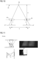
- the microlens array 19 is located between the two cameras 7 and 8 below the two cameras 7 and 8 as depicted in Figure 9 that shows a side view of the cameras 7 and 8 and the microlens array 19 of the projector 4.
- the microlens array 19 is arranged such that the projected dot pattern 6 falls at least partially within the scan area 26 of the cameras 7 and 8 for a large range of working distances WD.
- the working distance WD is the distance between the entry pupil of one of the cameras 7 and 8 and the scan area 26 measured along the axis 44 or 45 of the fields of view 27 or 28 of the camera 7 or 8.
- the microlens array 19 is tilted by an angle ⁇ in the range of 20° to 30° towards an axis at right angle to the beam axis 29 of the beam 25 in order to equalize the distance between the microlenses 32 and the surface 23 of the object 24.
- the angle ⁇ is generally more than half the angle ⁇ between the beam axis 29 and one of the axes of the field of view 44 and 45 if viewed along the longitudinal axis L of the scanner 3.
- Figure 10 illustrates the basic principle of computer stereovision.
- a point on the surface 23 of the object 24 is imaged on the sensor 47 of the first camera 7 at location x 1 and on the sensor 47 of the second camera 8 at location x 2 . These images points are sometimes referred to as homologous points in both digital images.
- the centers of both sensor 47 are separated by the baseline b.
- the sum x 1 + x 2 is the so-called disparity.
- the disparity is thus inversely proportional to the distance d of the dot 36.
- a so-called disparity map can be generated which show the disparity of each image point within the scan area 26.
- Graphic representations of disparity maps are usually encoded in a gray scale, wherein the gray level is inversely proportional to the disparity. That means that a point on the surface 23 of the object 24 at a smaller working distance WD appears to be brighter that a point on the surface 23 of the object 24 at a greater working distance WD.
- Figure 11 show the spatial relations between projector 4 and cameras 7 and 8 at a working distance of 8 mm.
- the upper diagrams contain the left digital image of the dot pattern 6 taken by the first camera 7 and the right digital image taken by the second camera 8.
- the lower diagram shows the resulting disparity map that is calculated based on the scan area 26 in which the digital left image and the digital right image overlap.
- Figures 12 to 16 correspond to Figure 11 but with the working distances of 10 mm, 12 mm, 14 mm, 16 mm and 18 mm.
- the disparity maps the disparity becomes increasingly darker indicating smaller disparity values corresponding to the increase of the working distance.
- the disparity is diminishing but still sufficiently great for determining the distance with sufficient accuracy.
- the digital images taken by the two cameras 7 and 8 are processed according to the principle of active stereo vision (ASV), which, as such, is a method well-known in the art.
- ASV active stereo vision
- structured light is projected onto the object 24 and the three-dimensional object 24 is reconstructed by determining the disparity in the overlapping scan area 26 based on pairs of digital images which are taken by at least one pair of cameras that are located at different locations.
- Figure 17 illustrates the principal steps of the method for reconstructing a three-dimensional image based on the digital images taken by the first camera 7 and second camera 8.
- the method may be performed by the processor 13 of the data processing unit 11 based on the digital images recorded by the cameras 7 and 8.
- these digital images are also referred to as frames.
- the method starts with an image capturing 50, a method step in which a series of digital images in true color with high density image quality generated by the cameras 7 and 8.
- the digital images or frames are taken by the first camera 7 and the second camera in a synchronized manner.
- the frame rate is typically in the range of 50 to 80 frames/sec.
- the frames are preprocessed.
- the imaged tissue may be automatically classified.
- Image regions relating to soft tissue are removed from the frames and margins between various objects are automatically detected.
- These tasks may be performed by a neural network or other forms of artificial intelligence.
- a method core 70 the information on the three-dimensional structure of the scanned dentition 2 is extracted from the image. For instance, depth maps are generated based on the disparity maps, the individual depth maps relating to different positions of the intraoral scanner 3 are combined and a mesh defining the surface of the dentition 2 is formed.
- the three-dimensional model of the dentition 2 is formed.
- a visualization step 90 the constructed three-dimensional model can finally be visualized on the display 16 of the data processing unit 11.
- the tree-dimensional model may be edited by the operator and finalized.
- FIG. 18 show further detail of the preprocessing 60.
- the preprocessing starts with a frame validation 61.
- the frames are analyzed to verify if they have the expected information content in order to make sure that the frames show an oral cavity.
- the frame validation 61 is followed by a frame conditioning 62.
- the frames are prepared for the next processing step.
- the frames are rescaled, cropped, flipped and deskewed or equalized.
- the type of tissues imaged in the frames are segmented in a segmentation step 63.
- Figure 19 further illustrates the core of the method.
- a rectification 71 is performed.
- the rectification 71 applies to corresponding frames generated by the first camera 7 and the second camera 8 at the same point of time. Both frames are remapped so that homologous points in the two frames lay on horizontal lines.
- a subsequent depth map generation 72 the homologous points in the two frames are matched and the disparity between them is stored in a disparity map. From the disparity map, a depth map of the scene is obtained according to the principles of stereovision as set forth above in connection of Figure 10 .
- the newly generated depth map is added to the previous ones by registration 73 using a registration algorithm, based on matching of homologous three-dimensional points of the depth maps to form a global point cloud.
- the resulting point cloud is subjected to a progressive meshing 74.
- the progressive meshing 74 allows to visualize the incrementally growing three-dimensional scene in real time on the display 16.
- Figure 20 shows further details of the subsequent model generation 80.
- segmentation and cluster removal 82 group of points which represent cluster not belonging to the surface 32 are recognized and removed from the point cloud to avoid protrusions of the final mesh.
- the number of points in the point cloud is subsequently reduced.
- vertexes in the point cloud which are at zero Euclidean distance are merged.
- a spatial filter 84 may be applied, which maintains the same topology as the original point cloud, but includes only a fraction of the original points.
- the filtered and decimated point cloud is then used in a 3D mesh reconstruction 85 to obtain a so-called watertight mesh surface based on the points positions and surface normals.
- a mesh cropping 86 is then performed on the watertight mesh surface to limit its extension of the original point cloud as well as to remove eventual isolated polygons.
- color mapping 87 the color information contained in color images of the scene may reassigned to the mesh surface all over the mesh.
- Mesh smoothing 88 may finally be used to regularize the surface and reduce polygon noise.
- Figure 21 illustrates the results of a test performed with the intraoral scanning system described herein.
- the intraoral scanning system was tested by scanning a tooth surface at a working distance of 10 mm using a microlens array 19 having a total of 1800 microlenses 32.
- the grey shading indicates the accuracy of the reconstructed three-dimensional model.
- the mean accuracy is in the range of 14 ⁇ m.
- the accuracy over the whole three-dimensional model varied according to a distribution having a variance ⁇ in the range of 13 ⁇ m.
- the system and the method described herein are based on the principle of active stereo vision (ASV). It should, however, be noted that the images can also be evaluated based on the principle of structured-light stereo (SLS). In this method, the differences in pairs of images are evaluated as described herein according to the principles of active stereo vision. Additionally, the images of each camera are evaluated for deviations from a reference images at a reference distance. From these differences a depth map can be calculated. In the art, this additional evaluation is also referred to as triangulation. One problem with triangulation, however, is the calibration of the reference images. Therefore, considerable effort is needed for retrieving the additional depth information by triangulation.
- ASV active stereo vision
- SLS structured-light stereo
- the laser diode 17 and the secondary radiation source may be activated alternatively and corresponding images may be taken by the cameras 7 and 8.
- the images taken under illumination by the secondary radiation source may then be used for the color mapping 87 for generating a three-dimensional model with colored surfaces of the dentition 2.
- the data processing unit 11 can be a computer having at least one physical or logical processor 13.
- the data processing unit 11 can also be implemented on several physical computers or can be an integrated device including the display 16.
- the method can be implemented by a computer program product, that contains code for implementing the method described herein, if the code is executed by a processor either in the data processing unit 11 or in some other entity.
- the computer program product may be code stored on a computer readable data carrier such as a disc, a compact disc or a digital versatile disc or the like.
- the computer program product may also be code stored on a data storage unit on a server or an array of servers. Such a data storage unit may be a hard disc or an array of hard disc or the like.
- the data carrier may also be an electrical carrier signal that can be used for transferring the code from a server, which can be used for downloading the program code to a client.
Landscapes
- Health & Medical Sciences (AREA)
- Life Sciences & Earth Sciences (AREA)
- Engineering & Computer Science (AREA)
- Physics & Mathematics (AREA)
- Surgery (AREA)
- Animal Behavior & Ethology (AREA)
- General Health & Medical Sciences (AREA)
- Public Health (AREA)
- Veterinary Medicine (AREA)
- Optics & Photonics (AREA)
- Dentistry (AREA)
- Oral & Maxillofacial Surgery (AREA)
- Biophysics (AREA)
- Biomedical Technology (AREA)
- Heart & Thoracic Surgery (AREA)
- Pathology (AREA)
- Medical Informatics (AREA)
- Molecular Biology (AREA)
- Radiology & Medical Imaging (AREA)
- Nuclear Medicine, Radiotherapy & Molecular Imaging (AREA)
- Epidemiology (AREA)
- Theoretical Computer Science (AREA)
- General Physics & Mathematics (AREA)
- Software Systems (AREA)
- Computer Graphics (AREA)
- General Engineering & Computer Science (AREA)
- Architecture (AREA)
- Computer Hardware Design (AREA)
- Geometry (AREA)
- Computer Vision & Pattern Recognition (AREA)
- Audiology, Speech & Language Pathology (AREA)
- Mathematical Physics (AREA)
- Databases & Information Systems (AREA)
- Data Mining & Analysis (AREA)
- Dental Tools And Instruments Or Auxiliary Dental Instruments (AREA)
- Stereoscopic And Panoramic Photography (AREA)
- Image Analysis (AREA)
- Length Measuring Devices By Optical Means (AREA)
Priority Applications (6)
| Application Number | Priority Date | Filing Date | Title |
|---|---|---|---|
| EP21212940.7A EP4193905A1 (fr) | 2021-12-07 | 2021-12-07 | Scanner intra-oral, système de balayage intra-oral, procédé permettant d'effectuer des balayages intra-oraux et produit-programme informatique |
| US18/717,421 US20250040798A1 (en) | 2021-12-07 | 2022-12-07 | Intraoral Scanner, Intraoral Scanning System, Method for Performing Intraoral Scans and Computer Program Product |
| PCT/EP2022/084873 WO2023104929A1 (fr) | 2021-12-07 | 2022-12-07 | Scanner intra-buccal, système de balayage intra-buccal, procédé de réalisation de balayages intra-buccaux et produit programme informatique |
| CN202280081233.1A CN118369036A (zh) | 2021-12-07 | 2022-12-07 | 口内扫描仪、口内扫描系统、用于执行口内扫描的方法和计算机程序产品 |
| KR1020247022272A KR20240118827A (ko) | 2021-12-07 | 2022-12-07 | 구강 내 스캐너, 구강 내 스캐닝 시스템, 구강 내 스캔을 수행하는 방법 및 컴퓨터 프로그램 제품 |
| JP2024534120A JP2025501873A (ja) | 2021-12-07 | 2022-12-07 | 口腔内スキャナ、口腔内スキャニングシステム、口腔内スキャン方法及びコンピュータプログラム製品 |
Applications Claiming Priority (1)
| Application Number | Priority Date | Filing Date | Title |
|---|---|---|---|
| EP21212940.7A EP4193905A1 (fr) | 2021-12-07 | 2021-12-07 | Scanner intra-oral, système de balayage intra-oral, procédé permettant d'effectuer des balayages intra-oraux et produit-programme informatique |
Publications (1)
| Publication Number | Publication Date |
|---|---|
| EP4193905A1 true EP4193905A1 (fr) | 2023-06-14 |
Family
ID=78824744
Family Applications (1)
| Application Number | Title | Priority Date | Filing Date |
|---|---|---|---|
| EP21212940.7A Pending EP4193905A1 (fr) | 2021-12-07 | 2021-12-07 | Scanner intra-oral, système de balayage intra-oral, procédé permettant d'effectuer des balayages intra-oraux et produit-programme informatique |
Country Status (6)
| Country | Link |
|---|---|
| US (1) | US20250040798A1 (fr) |
| EP (1) | EP4193905A1 (fr) |
| JP (1) | JP2025501873A (fr) |
| KR (1) | KR20240118827A (fr) |
| CN (1) | CN118369036A (fr) |
| WO (1) | WO2023104929A1 (fr) |
Cited By (2)
| Publication number | Priority date | Publication date | Assignee | Title |
|---|---|---|---|---|
| WO2023229834A1 (fr) * | 2022-05-26 | 2023-11-30 | Align Technology, Inc. | Scanner intra-buccal avec projecteur de motif à guides d'ondes |
| EP4640132A1 (fr) * | 2024-04-26 | 2025-10-29 | Shanghai Alliedstar Medical Technology Co., Ltd. | Procédé et dispositif de réglage du champ de vision pour scanners intra-buccaux |
Families Citing this family (1)
| Publication number | Priority date | Publication date | Assignee | Title |
|---|---|---|---|---|
| KR102917271B1 (ko) * | 2025-03-12 | 2026-01-26 | 주식회사 마이크로픽스 | 마이크로렌즈 어레이를 이용한 핸디형 구강 스캐너 |
Citations (4)
| Publication number | Priority date | Publication date | Assignee | Title |
|---|---|---|---|---|
| US20060227216A1 (en) | 2003-07-28 | 2006-10-12 | Sopro | Device for the detection and characterization of biological tissue |
| CN108175535A (zh) * | 2017-12-21 | 2018-06-19 | 北京理工大学 | 一种基于微透镜阵列的牙科三维扫描仪 |
| WO2019236934A1 (fr) | 2018-06-08 | 2019-12-12 | Dentsply Sirona Inc. | Dispositif, procédé et système pour générer des motifs de projection dynamique dans une caméra |
| US20190388194A1 (en) * | 2018-06-22 | 2019-12-26 | Align Technology, Inc. | Light field intraoral 3d scanner with structured light illumination |
Family Cites Families (6)
| Publication number | Priority date | Publication date | Assignee | Title |
|---|---|---|---|---|
| DE10238556A1 (de) * | 2002-08-22 | 2004-03-04 | Kaltenbach & Voigt Gmbh & Co. Kg | Ärztliches oder zahnärztliches stabförmiges Handstück mit einem Display |
| US9261356B2 (en) * | 2014-07-03 | 2016-02-16 | Align Technology, Inc. | Confocal surface topography measurement with fixed focal positions |
| US10531074B2 (en) * | 2015-10-16 | 2020-01-07 | CapsoVision, Inc. | Endoscope employing structured light providing physiological feature size measurement |
| US10835360B2 (en) * | 2016-04-01 | 2020-11-17 | Research and Development International Corporation | Advanced periodontal endoscope and methods |
| CA3284897A1 (en) * | 2017-04-20 | 2025-10-30 | Resnent, Llc | Flexible-rigid hybrid endoscope and instrument attachments |
| CN107295227A (zh) * | 2017-05-27 | 2017-10-24 | 欧阳聪星 | 一种口腔内窥器 |
-
2021
- 2021-12-07 EP EP21212940.7A patent/EP4193905A1/fr active Pending
-
2022
- 2022-12-07 CN CN202280081233.1A patent/CN118369036A/zh active Pending
- 2022-12-07 WO PCT/EP2022/084873 patent/WO2023104929A1/fr not_active Ceased
- 2022-12-07 JP JP2024534120A patent/JP2025501873A/ja active Pending
- 2022-12-07 KR KR1020247022272A patent/KR20240118827A/ko active Pending
- 2022-12-07 US US18/717,421 patent/US20250040798A1/en active Pending
Patent Citations (4)
| Publication number | Priority date | Publication date | Assignee | Title |
|---|---|---|---|---|
| US20060227216A1 (en) | 2003-07-28 | 2006-10-12 | Sopro | Device for the detection and characterization of biological tissue |
| CN108175535A (zh) * | 2017-12-21 | 2018-06-19 | 北京理工大学 | 一种基于微透镜阵列的牙科三维扫描仪 |
| WO2019236934A1 (fr) | 2018-06-08 | 2019-12-12 | Dentsply Sirona Inc. | Dispositif, procédé et système pour générer des motifs de projection dynamique dans une caméra |
| US20190388194A1 (en) * | 2018-06-22 | 2019-12-26 | Align Technology, Inc. | Light field intraoral 3d scanner with structured light illumination |
Cited By (2)
| Publication number | Priority date | Publication date | Assignee | Title |
|---|---|---|---|---|
| WO2023229834A1 (fr) * | 2022-05-26 | 2023-11-30 | Align Technology, Inc. | Scanner intra-buccal avec projecteur de motif à guides d'ondes |
| EP4640132A1 (fr) * | 2024-04-26 | 2025-10-29 | Shanghai Alliedstar Medical Technology Co., Ltd. | Procédé et dispositif de réglage du champ de vision pour scanners intra-buccaux |
Also Published As
| Publication number | Publication date |
|---|---|
| CN118369036A (zh) | 2024-07-19 |
| KR20240118827A (ko) | 2024-08-05 |
| WO2023104929A1 (fr) | 2023-06-15 |
| JP2025501873A (ja) | 2025-01-24 |
| US20250040798A1 (en) | 2025-02-06 |
Similar Documents
| Publication | Publication Date | Title |
|---|---|---|
| US20250040798A1 (en) | Intraoral Scanner, Intraoral Scanning System, Method for Performing Intraoral Scans and Computer Program Product | |
| US8432435B2 (en) | Ray image modeling for fast catadioptric light field rendering | |
| US8494252B2 (en) | Depth mapping using optical elements having non-uniform focal characteristics | |
| EP2568253B1 (fr) | Procédé et système de mesure de lumière structurée | |
| CN111462299B (zh) | 基于深度学习的非视域飞秒成像三维重建方法及装置 | |
| Silvester et al. | A critical assessment of the potential for structure‐from‐motion photogrammetry to produce high fidelity 3D dental models | |
| CN102713671A (zh) | 点群数据处理装置、点群数据处理方法和点群数据处理程序 | |
| JP2008145431A (ja) | 3次元表面形状再構築のための装置および方法 | |
| JP2001116526A (ja) | 3次元形状計測装置 | |
| JP3409873B2 (ja) | 物体入力装置 | |
| KR20240165459A (ko) | 고밀도 광 패턴을 투영하기 위한 구강 내 3d 스캐닝 디바이스 | |
| JP2007508557A (ja) | 三次元物体を走査するための装置 | |
| CN118265889A (zh) | 利用由至少一个平行辐射源生成的结构光来测量场景的深度信息的方法和装置 | |
| JP6614905B2 (ja) | 三次元計測装置およびその制御方法 | |
| JP2004110804A (ja) | 3次元画像撮影装置及び方法 | |
| CN115100350B (zh) | 一种基于单目视觉的口腔建模方法、系统和存储介质 | |
| CN114782632A (zh) | 一种图像重建方法、装置及设备 | |
| KR20250135600A (ko) | 구강 모델의 세그멘테이션 방법 및 이를 실행하기 위하여 기록매체에 기록된 컴퓨터 프로그램 | |
| Ali et al. | Teeth model reconstruction based on multiple view image capture | |
| JP2005043083A (ja) | 撮影誤差低減システム、撮影誤差低減方法、プログラム、及び記録媒体 | |
| JP2002206919A (ja) | 3次元形状計測装置および3次元形状計測方法 | |
| JP2002013918A (ja) | 3次元画像生成装置および3次元画像生成方法 | |
| JPH0789057B2 (ja) | 距離測定装置 | |
| JP2002031511A (ja) | 3次元デジタイザ | |
| JP2006308452A (ja) | 3次元形状計測方法および装置 |
Legal Events
| Date | Code | Title | Description |
|---|---|---|---|
| PUAI | Public reference made under article 153(3) epc to a published international application that has entered the european phase |
Free format text: ORIGINAL CODE: 0009012 |
|
| STAA | Information on the status of an ep patent application or granted ep patent |
Free format text: STATUS: THE APPLICATION HAS BEEN PUBLISHED |
|
| AK | Designated contracting states |
Kind code of ref document: A1 Designated state(s): AL AT BE BG CH CY CZ DE DK EE ES FI FR GB GR HR HU IE IS IT LI LT LU LV MC MK MT NL NO PL PT RO RS SE SI SK SM TR |
|
| STAA | Information on the status of an ep patent application or granted ep patent |
Free format text: STATUS: REQUEST FOR EXAMINATION WAS MADE |
|
| 17P | Request for examination filed |
Effective date: 20231213 |
|
| RBV | Designated contracting states (corrected) |
Designated state(s): AL AT BE BG CH CY CZ DE DK EE ES FI FR GB GR HR HU IE IS IT LI LT LU LV MC MK MT NL NO PL PT RO RS SE SI SK SM TR |
|
| STAA | Information on the status of an ep patent application or granted ep patent |
Free format text: STATUS: EXAMINATION IS IN PROGRESS |
|
| 17Q | First examination report despatched |
Effective date: 20251112 |