EP4193941A2 - Dispositifs de stabilisation - Google Patents
Dispositifs de stabilisation Download PDFInfo
- Publication number
- EP4193941A2 EP4193941A2 EP22203686.5A EP22203686A EP4193941A2 EP 4193941 A2 EP4193941 A2 EP 4193941A2 EP 22203686 A EP22203686 A EP 22203686A EP 4193941 A2 EP4193941 A2 EP 4193941A2
- Authority
- EP
- European Patent Office
- Prior art keywords
- legs
- leg
- stabilization
- cross
- stabilization device
- Prior art date
- Legal status (The legal status is an assumption and is not a legal conclusion. Google has not performed a legal analysis and makes no representation as to the accuracy of the status listed.)
- Pending
Links
Images




Classifications
-
- A—HUMAN NECESSITIES
- A61—MEDICAL OR VETERINARY SCIENCE; HYGIENE
- A61B—DIAGNOSIS; SURGERY; IDENTIFICATION
- A61B17/00—Surgical instruments, devices or methods
- A61B17/56—Surgical instruments or methods for treatment of bones or joints; Devices specially adapted therefor
- A61B17/58—Surgical instruments or methods for treatment of bones or joints; Devices specially adapted therefor for osteosynthesis, e.g. bone plates, screws or setting implements
- A61B17/68—Internal fixation devices, including fasteners and spinal fixators, even if a part thereof projects from the skin
-
- A—HUMAN NECESSITIES
- A61—MEDICAL OR VETERINARY SCIENCE; HYGIENE
- A61B—DIAGNOSIS; SURGERY; IDENTIFICATION
- A61B17/00—Surgical instruments, devices or methods
- A61B17/064—Surgical staples, i.e. penetrating the tissue
- A61B17/0642—Surgical staples, i.e. penetrating the tissue for bones, e.g. for osteosynthesis or connecting tendon to bone
-
- A—HUMAN NECESSITIES
- A61—MEDICAL OR VETERINARY SCIENCE; HYGIENE
- A61B—DIAGNOSIS; SURGERY; IDENTIFICATION
- A61B17/00—Surgical instruments, devices or methods
- A61B17/064—Surgical staples, i.e. penetrating the tissue
-
- A—HUMAN NECESSITIES
- A61—MEDICAL OR VETERINARY SCIENCE; HYGIENE
- A61B—DIAGNOSIS; SURGERY; IDENTIFICATION
- A61B17/00—Surgical instruments, devices or methods
- A61B17/064—Surgical staples, i.e. penetrating the tissue
- A61B17/0643—Surgical staples, i.e. penetrating the tissue with separate closing member, e.g. for interlocking with staple
-
- A—HUMAN NECESSITIES
- A61—MEDICAL OR VETERINARY SCIENCE; HYGIENE
- A61B—DIAGNOSIS; SURGERY; IDENTIFICATION
- A61B17/00—Surgical instruments, devices or methods
- A61B17/064—Surgical staples, i.e. penetrating the tissue
- A61B17/0644—Surgical staples, i.e. penetrating the tissue penetrating the tissue, deformable to closed position
-
- A—HUMAN NECESSITIES
- A61—MEDICAL OR VETERINARY SCIENCE; HYGIENE
- A61B—DIAGNOSIS; SURGERY; IDENTIFICATION
- A61B17/00—Surgical instruments, devices or methods
- A61B17/068—Surgical staplers, e.g. containing multiple staples or clamps
- A61B17/0682—Surgical staplers, e.g. containing multiple staples or clamps for applying U-shaped staples or clamps, e.g. without a forming anvil
-
- A—HUMAN NECESSITIES
- A61—MEDICAL OR VETERINARY SCIENCE; HYGIENE
- A61B—DIAGNOSIS; SURGERY; IDENTIFICATION
- A61B17/00—Surgical instruments, devices or methods
- A61B17/08—Wound clamps or clips, i.e. not or only partly penetrating the tissue ; Devices for bringing together the edges of a wound
- A61B17/083—Clips, e.g. resilient
-
- A—HUMAN NECESSITIES
- A61—MEDICAL OR VETERINARY SCIENCE; HYGIENE
- A61B—DIAGNOSIS; SURGERY; IDENTIFICATION
- A61B17/00—Surgical instruments, devices or methods
- A61B17/10—Surgical instruments, devices or methods for applying or removing wound clamps, e.g. containing only one clamp or staple; Wound clamp magazines
-
- A—HUMAN NECESSITIES
- A61—MEDICAL OR VETERINARY SCIENCE; HYGIENE
- A61B—DIAGNOSIS; SURGERY; IDENTIFICATION
- A61B17/00—Surgical instruments, devices or methods
- A61B17/56—Surgical instruments or methods for treatment of bones or joints; Devices specially adapted therefor
- A61B17/58—Surgical instruments or methods for treatment of bones or joints; Devices specially adapted therefor for osteosynthesis, e.g. bone plates, screws or setting implements
- A61B17/68—Internal fixation devices, including fasteners and spinal fixators, even if a part thereof projects from the skin
- A61B17/84—Fasteners therefor or fasteners being internal fixation devices
- A61B17/846—Nails or pins, i.e. anchors without movable parts, holding by friction only, with or without structured surface
- A61B17/848—Kirschner wires, i.e. thin, long nails
-
- A—HUMAN NECESSITIES
- A61—MEDICAL OR VETERINARY SCIENCE; HYGIENE
- A61B—DIAGNOSIS; SURGERY; IDENTIFICATION
- A61B17/00—Surgical instruments, devices or methods
- A61B2017/00831—Material properties
- A61B2017/00867—Material properties shape memory effect
-
- A—HUMAN NECESSITIES
- A61—MEDICAL OR VETERINARY SCIENCE; HYGIENE
- A61B—DIAGNOSIS; SURGERY; IDENTIFICATION
- A61B17/00—Surgical instruments, devices or methods
- A61B17/064—Surgical staples, i.e. penetrating the tissue
- A61B2017/0645—Surgical staples, i.e. penetrating the tissue being elastically deformed for insertion
-
- A—HUMAN NECESSITIES
- A61—MEDICAL OR VETERINARY SCIENCE; HYGIENE
- A61B—DIAGNOSIS; SURGERY; IDENTIFICATION
- A61B17/00—Surgical instruments, devices or methods
- A61B17/064—Surgical staples, i.e. penetrating the tissue
- A61B2017/0646—Surgical staples, i.e. penetrating the tissue for insertion into cartillege, e.g. meniscus
-
- A—HUMAN NECESSITIES
- A61—MEDICAL OR VETERINARY SCIENCE; HYGIENE
- A61B—DIAGNOSIS; SURGERY; IDENTIFICATION
- A61B17/00—Surgical instruments, devices or methods
- A61B17/56—Surgical instruments or methods for treatment of bones or joints; Devices specially adapted therefor
- A61B2017/564—Methods for bone or joint treatment
-
- A—HUMAN NECESSITIES
- A61—MEDICAL OR VETERINARY SCIENCE; HYGIENE
- A61B—DIAGNOSIS; SURGERY; IDENTIFICATION
- A61B17/00—Surgical instruments, devices or methods
- A61B17/56—Surgical instruments or methods for treatment of bones or joints; Devices specially adapted therefor
- A61B17/58—Surgical instruments or methods for treatment of bones or joints; Devices specially adapted therefor for osteosynthesis, e.g. bone plates, screws or setting implements
- A61B17/68—Internal fixation devices, including fasteners and spinal fixators, even if a part thereof projects from the skin
- A61B2017/681—Alignment, compression, or distraction mechanisms
Definitions
- the present disclosure relates to the field of implants for use in medical procedures.
- stabilization devices described herein can be used to join target areas of tissue.
- Devices and methods of stabilization of tissue for use in orthopedic procedures may include plates, staples, and devices having a solid body.
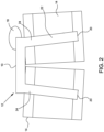
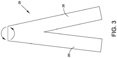
- FIGs. 1-3 depict prior art staples.
- staple 2 includes multiple legs 4.
- Bridging member 6 is formed such that distal ends 8 of legs 4 are closer together than ends 10 connected to bridging member 6.
- FIG. 2 depicts staple 12 positioned in tissue 14. Staples having bridges may cause soft tissue damage and/or irritation. As shown in FIG. 2 , bridge 16 protrudes beyond tissue 14. Thus, site 18 indicates a potential location of irritation in the surrounding soft tissue.
- distal ends 20 of legs 22 of staple 12 are positioned further apart than ends 24 connected to bridging member 16. As shown in FIG. 2 , positioning of the distal ends may affect the ability of the staples to couple target areas of tissue such that the distance between the target areas is equidistant. In some instances, this variable distance between the legs may cause uneven compression across the site of the tissue repair which may lead to delayed and/or malunion of the target areas of the tissue being repaired.
- the target areas of the tissue may include bone, bone segments and/or adjacent areas of bone.
- legs 26, 26' have reduced torsional stability due to the geometry of staple 28 shown in FIGs. 2-3 .
- staple 28 has a triangular shaped profile.
- Implants for use in surgery need to be constructed in a manner that reduces or inhibits potential for irritation during use. Designs that provide surgeons with superior control, accuracy and performance are of particular interest. This results in reduced damage, heat and trauma to the tissues and leads to faster operations, more first-time results and an overall improvement in post-surgery healing.
- a stabilization device can include a first leg, a second leg substantially parallel to the first leg, and one or more cross-members coupling the first leg to the second leg.
- the one or more cross-members couple to the first and second legs at a predetermined distance from at least one end of each of the first and second legs.
- Each of the first and second legs includes an opening along longitudinal axes of the first and second legs.
- the first leg of stabilization device can be positioned substantially within a target area of tissue during use.
- first and second legs of the stabilization device are positioned completely within at least two target areas of tissue such that the stabilization device couples the at least two target areas of tissue during use.
- the one of more cross-members can extend from a first target area of tissue to a second target area of tissue at an interface of the first and second target areas. Further, during use the first leg can be positioned within the first target area and the second leg can be positioned within the second target area.
- the stabilization device can be secured to target tissue using one or more alignment elements during use.
- the stabilization device can be secured to target tissue using one or more pins during use.
- first and second legs and the one or more cross-member of the stabilization device can be formed from a metal alloys.
- the first and second legs and the one or more cross-members can be formed from Nitinol.
- An embodiment of a stabilization device can include a first leg and a second leg substantially parallel to the first leg.
- the stabilization device can also include one or more cross-members coupling the first leg to the second leg.
- the ends of each of the first and second legs can extend beyond an outermost edge of the cross-member such that a plane that includes a first end of the first leg and a first end of the second leg does not contact any of the one or more cross-members.
- the legs may extend beyond cross-member along a longitudinal axis of the legs.
- the stabilization device can include first and second legs and the one or more cross-members are formed from a metal alloy such as Nitinol.
- Each of the first and second legs of the stabilization device can include an opening along longitudinal axes of the first and second legs.
- the stabilization device can be secured to target areas of tissue using alignment elements such as pins during use.
- the stabilization device can be positioned within at least two target areas of tissue such that the stabilization device couples the at least two target areas of tissue and the one or more cross-members extend from the first target areas of tissue to the second target area of tissue at an interface of the at least two target areas during use.
- a stabilization device system can include a first alignment element, a second alignment element, a cut guide, an inserter device, and a stabilization device having a first leg, a second leg, and a cross-member coupling the first leg to the second leg.
- the stabilization device can include at least one end of each of the first and second legs extending beyond an outermost edge of the cross-member along a longitudinal axis of the stabilization device.
- the stabilization device can be secured to target areas of tissue using the first and second alignment elements, such as pins during use.
- An embodiment of an orthopedic stabilization device can include a first leg having a first opening, a second leg having a second opening, and a cross-member coupling the first leg to the second leg.
- alignment elements can be used for positioning the orthopedic stabilization device in target tissue.
- Alignment elements can be capable of coupling to openings of legs of the orthopedic stabilization device during use.
- the orthopedic stabilization device secures a target area of tissue during use.
- An embodiment of an orthopedic implant system can include at least two stabilization devices that include a first leg having a first opening, a second leg having a second opening, and a cross-member coupling the first leg to the second leg and alignment elements for coupling to openings of legs during use. At least two stabilization devices secure a target area of tissue during use.
- an orthopedic implant system can include at least two stabilization devices that can be positioned such that ends of first legs of each of the at least two stabilization devices are proximate to each other during use.
- an embodiment of an orthopedic implant system can include at least two stabilization devices that can be positioned such that cross-members are positioned proximate to each other during use.
- an orthopedic implant system can include at least two stabilization devices positioned such that cross-members are positioned proximate to each other and ends of first and second legs are positioned such that the first openings of the first legs are proximate to each other and the second openings of the second legs are proximate to each other.
- a stabilization device can include multiple legs.
- a stabilization device can include two legs that are substantially parallel. The legs can be positioned at opposite ends of one or more cross-members that couple the legs to each other. Ends of the legs can extend beyond an outermost edge of the cross-member.
- the stabilization devices of the present disclosure and elements thereof can be formed from a metal or an alloy.
- the legs and the cross-members can be formed from a metal alloy.
- the legs and the cross-members of the stabilization devices can be formed from a nickel titanium alloy such as Nitinol.
- the legs of the stabilization devices can include openings.
- the openings in the legs can be formed along longitudinal axes of the legs.
- the openings can be used to position and/or secure the stabilization device to the target tissues using alignment elements such as pins, k-wires, and/or screws.
- pins can be positioned in the target tissues and then the stabilization device can be positioned based on the locations of the pins.
- the stabilization device can be secured to the target tissue using pins during use.
- a stabilization device system can include alignments elements, such as pins, a cut guide, drill guides, and a stabilization device that includes legs and at least one cross-member. Pins can be used to position and/or secure stabilization devices to a target tissue. For example, some embodiments of stabilization device systems can include at least two pins for each stabilization device.
- the one or more cross-members can couple the legs to each other. In some embodiments, ends of the legs extend beyond an outermost edge of the cross-members.
- An orthopedic implant can include legs that are constructed such that they engage with alignment elements. Alignment elements such as pins, screws, k-wires, or the like can be used to position a stabilization device. In some embodiments, the stabilization devices can be secured to the target tissue using one or more alignment elements during use.
- stabilization devices can include alignment elements capable of both positioning and securing a stabilization device.
- alignment elements can include but are not limited to pins, screws, k-wires, or like.
- the stabilization devices can include structures and/or elements that engage alignment elements such that the stabilization devices can be positioned and/or secured to a target tissue.
- each of the legs can include an opening that extends along the longitudinal axis of the leg.
- Such openings can have a predetermined geometry that conforms to a selected alignment element such as a pin, screw, k-wire, or the like.
- both legs have openings extending from a first end to second end of the leg such that alignment elements positioned in the openings extend a predetermined distance in the openings.
- pins can extend a full length of the openings.
- the cross-members couple the legs to each other.
- the cross-members can couple the legs at predetermined positions along the length of the legs.
- the cross-members can have varying geometries.
- a cross-member can have an arcuate structure such as an arc or S-shaped structure, a truss structure, a triangular structure, an inverted triangular structure, etc.
- Some embodiments can include multiple cross-members connecting legs.
- An orthopedic implant system can include two or more stabilization devices.
- Each of the stabilization devices can include legs having openings and a cross-member connecting the legs. The legs can be secured to a target area of a tissue using alignment elements coupled to the openings during use.
- the at least two stabilization devices secure a target area of the tissue during use.
- Stabilization devices can be positioned such that ends of first legs are positioned proximate to each other during use. In alternate embodiments, stabilization devices can be positioned such that cross-members are positioned proximate to each other during use.
- multiple stabilization devices can be positioned such that the cross-members are positioned proximate to each other and ends of the legs are positioned such that the openings of a first legs are proximate to each other and the second openings of the second legs are proximate to each other during use.
- a method of implanting a stabilization device can include drilling a first pilot hole, positioning a first alignment pin in the first pilot hole, drilling a second pilot hole using a drill guide, positioning a second alignment pin in the second pilot hole, positioning a cut guide over the first and second alignment pins, making a cut for a cross-member of the stabilization device and inserting stabilization device.
- Methods for implanting a stabilization device can include drilling pilot holes.
- pilot holes can be drilled using a drill guide. Pilot holes can be drilled at selected locations in target tissues. The locations for the pilot holes can be selected based on the type of procedure, type of injury, anatomy of the patient, etc.
- the method also includes positioning an alignment element in one of the pilot hole. For example, an alignment pin can be positioned in each of the pilot holes.
- a cut guide can be positioned over the alignment elements. The cut guide can be used to make a cut for a cross-member of the stabilization device.
- the stabilization device can then be implanted. In some instances, portions of the stabilization device can engage with the alignment elements.
- the stabilization devices described herein can be used to fix and/or fuse target areas of a tissue.
- the stabilization devices can be used to fix and/or fuse to separate areas of a bone.
- the stabilization devices and elements thereof can be formed from a material usable in the prosthetic arts, including, but not limited to metals such as titanium and/or tantalum, alloys such as titanium alloys, nickel titanium alloys (i.e., Nitinol), chrome cobalt, surgical steel, or any other total joint replacement metal and/or ceramic, sintered glass, artificial bone, or a combination thereof.
- portions of a stabilization device can be formed from a suitable durable biologic material or a combination of metal and biologic material, such as a biocompatible bone-filling material.
- Stabilization devices as described herein can be formed utilizing one or more methods including, but not limited to machining such as electrical discharge machining, for example, wire electrical discharge machining (WEDM), molding, additive manufacturing such as 3D printing or laser sintering, and/or extrusion.
- machining such as electrical discharge machining, for example, wire electrical discharge machining (WEDM), molding, additive manufacturing such as 3D printing or laser sintering, and/or extrusion.
- WEDM wire electrical discharge machining
- molding additive manufacturing such as 3D printing or laser sintering, and/or extrusion.
- the legs and the cross-members of an embodiment can be formed from a metal alloy.
- shape memory materials such as nickel titanium alloys can be used for orthopedic implants such as stabilization devices.
- the legs and the cross-members of the stabilization devices in some embodiments can be formed from a nickel titanium alloy such as Nitinol.
- Nitinol has historically had various uses in medicine, for example, in cardiac stents, orthodontic wires, and musculoskeletal implants due to Nitinol's shape memory properties
- an orthopedic implant is a stabilization device 30.
- Stabilization device 30 can be used to join and compress two tissue parts A and B across an interface C to promote healing and formation of a permanent joint at the interface C between the two tissue parts A and B.
- the two tissue parts A and B are two ends of a long bone facing across the interface C.
- the interface C can be the result of a fracture of the long bone or as a result of an osteotomy.
- stabilization devices 30 can be useful in joint fusions including osteotomy procedures.
- stabilization devices can be used in osteotomy procedures such as Evans's osteotomy, Cotton osteotomy, and tibial osteotomy to assist in healing of the two bone parts involved in the osteotomy.
- each of the bone pieces A and B comprises cancellous bone portions 32, 34 and their respective cortical bone portions 33, 35.
- stabilization devices can provide the selected spacing between target areas of tissue.
- stabilization device 30 is secured between two target areas of tissue.
- Stabilization devices 30 can be formed utilizing one or more methods including, but not limited to machining such as electrical discharge machining, for example, wire electrical discharge machining (WEDM), molding, additive manufacturing such as 3D printing or laser sintering, and/or extrusion.
- machining such as electrical discharge machining, for example, wire electrical discharge machining (WEDM), molding, additive manufacturing such as 3D printing or laser sintering, and/or extrusion.
- WEDM wire electrical discharge machining
- molding additive manufacturing such as 3D printing or laser sintering, and/or extrusion.
- FIG. 4 depicts stabilization device 30 positioned in target areas of tissue 32, 33, 34, 35.
- Stabilization device 30 includes two legs 36 and spacer structure 38 that includes cross-members 42, 42'. As shown, stabilization device 30 is implanted in target areas of tissue 32, 33, 34, 35.
- Positioning of stabilization device can be used to control the position of target areas relative to each other.
- a position for a stabilization device can be selected to provide a predetermined positioning of target areas 32, 33 relative to target area 34, 35.
- a stabilization device can be positioned within at least two target areas of tissue such that the stabilization device couples the at least two target areas of tissue at an interface.
- the stabilization device 30 is implanted in tissue parts A, B such that a portion of the stabilization device 30 crosses the interface C between the tissue parts A, B.
- a stabilization device 30 can promote healing and formation of a permanent joint at the interface C between the two tissue parts A and B.
- the stabilization device 30 is positioned within target areas, for example tissue parts A, B, and only extends beyond an outer surface of individual target areas at the interface C of the tissue parts A, B.
- the two legs 36 of the stabilization device 30 do not extend along the longitudinal axis of the legs of the stabilization device beyond target areas of tissue 32, 33, 34, 35.
- the legs 36 of the stabilization device 30 should not protrude beyond the surface of the tissue to reduce irritation of the surrounding tissues.
- the stabilization device embodiment shown in FIG. 4 can be positioned in a target area of bone such that the legs 36 of the stabilization device 30 do not protrude beyond the surface of the bone to reduce irritation of the surrounding tissues.
- elements of stabilization devices such as legs, spacer elements, and/or cross-members should not protrude beyond surfaces of target areas except at an interface between the target areas.
- legs 36 do not extend into surrounding tissues 40.
- Spacer structures may have varying geometries.
- Spacer structures may include cross-members of varying shapes. Some embodiments can include multiple cross-members connecting legs.
- a cross-member can be an arcuate structure such as an arc, an S-structure, a truss structure, a triangular structure, an inverted triangular structure, etc.
- Cross-members can couple the legs to each other.
- spacer structure 38 includes cross-members 42, 42'.
- Cross-members can couple to the legs at predetermined positions along the length of the legs. Locations of the coupling can be selected based on tissue type, location and/or type of injury, anatomy of patient, desired distance between the target tissue areas, desired compression, and/or needs of the surgical team. For example, in the embodiment shown in FIG. 4 the cross-members 42, 42' are positioned symmetrically relative to a horizontal centerline 44 of the stabilization device 30.
- a stabilization device utilizing legs and cross-members can be selected to provide a predetermined strength, compression, distance between target areas. In some embodiments, it may be desired to provide a stabilization device which provides one or more of the predetermined characteristics while reducing a footprint of the stabilization device in the body of the patient.
- a cross-member 46 is coupled to the legs 48, 48' near a proximate end 50 of the legs 48, 48'.
- the cross-member 46 is positioned such that the proximate ends 50 of the legs 48, 48' do extend beyond a plane of the outermost portions of cross-members.
- the embodiment of stabilization device shown in FIG. 5 when the embodiment of stabilization device shown in FIG. 5 is positioned in a target area of tissue the legs can be positioned such that the legs do not extend beyond the target area of tissue.
- the stabilization device can be positioned such that neither the legs or cross-members enter the surrounding tissue. In other words, the stabilization device can be positioned substantially within target areas of tissue.
- the stabilization device embodiment shown in FIG. 5 includes legs 48, 48' that are substantially parallel to each other.
- stabilization devices can be formed such that legs have a predetermined angle of entry into a target area such as a bone.
- a target area such as a bone.
- one end of legs of a stabilization device can diverge while the opposite ends of the legs converge.
- Cross-members 42, 42', 45 of FIGs. 4-5 have planar surfaces.
- the planar surfaces of the cross-members can aid in positioning of the stabilization devices during use.
- cross-members can have a width that differs from the height of the planar surface.
- FIG. 6 depicts a top view of a stabilization device 54 having a cross-member 56 and legs 58.
- the legs 58 of the stabilization device 54 include the openings 60. Openings in the legs can be formed along longitudinal axes of the legs. Openings can be used to position and/or secure the stabilization device to target areas of tissue using alignment elements such as pins, k-wires, and/or screws. Alignment elements can be constructed to engage an opening and/or a slot of a leg of the stabilization device. For example, a diameter of an alignment element can be substantially equal to or less than the diameter 64 of the opening 60 in the leg 64 shown in FIG. 6 .
- both legs 58 have openings 60 and slots 64 extending from a first end (not shown) to second end (not shown) of the legs.
- the alignment elements can be positioned in the openings such that they extend a predetermined distance in the openings. For example, in some instances pins can extend a full length of the openings. Alternatively, the alignment elements may extend only partially along a length of the openings. Alignment elements may be positioned such that an end of the alignment element extends from a position in the target tissue through a portion of the opening. Alignment elements, such as pins, may be fully encompassed in the openings. For example, when a stabilization device is positioned such that the openings are positioned over an entire length of the pins.
- alignment elements can be removed after positioning of the stabilization device. For example, a portion of an alignment element can be removed after the stabilization device is positioned.
- the alignment elements can ensure that implants, such as stabilization devices, maintain a predetermined position relative to one or more target areas of tissue.
- implants such as stabilization devices
- an orthopedic implant such as a stabilization device can be secured to one or more target areas of tissue during use.
- alignment elements such as pins
- the stabilization device can be positioned based on locations of the pins.
- Stabilization devices can be secured to target areas of tissues using alignment elements during use.
- FIG. 7 depicts legs 66 having both openings 68 and slot 70.
- the slot 70 extends the full length of the leg 66.
- Alignment elements such as pins, screws, k-wires, or the like may be used to position a stabilization device.
- stabilization devices can be secured to target tissue using alignment elements during use.
- some embodiments of cross-members 72 have a thickness 74 that is substantially smaller than a length 76. Proportions of the stabilization devices and elements thereof may be selected based on desired properties for the stabilization devices. For example, cross-member dimensions can be selected based on target areas of tissue to be fused, fixed, and/or stabilized, determinations of the surgical team, type of injury, desired compression or extension between the target areas of tissue, desired strength of the stabilization device, etc.
- openings can include threads. Threads can be constructed to accommodate the threaded heads of screws or other threaded elements.
- the threaded screw holes can be configured to accommodate uni-axial locking screws or poly-axial locking screws.
- the screws can be locking screws, non-locking screws, or compression screws.
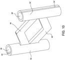
- FIGs. 8-10 depict an embodiment of the stabilization device 78 having two cross-members 80, 80'.
- Cross-members 80, 80' connect to each other and the legs 82, 82'.
- the cross-members can each separately connect to the legs.
- a number of cross-members in a stabilization device can vary. Numbers and/or configurations of the cross-members may be determined by requirements of use.
- the slots 84, 84' and the openings 86, 86' extend the full length of the legs 82, 82'.
- the legs can engage in a friction fit with the alignment elements or portions thereof.
- the legs and/or the alignment elements can include engagement elements to couple the legs and the alignment elements together.
- alignment elements can include a protrusion that engages with the slots in the legs.
- multiple pilot holes can be drilled into the target areas of tissue to receive the alignment elements and/or the legs of a stabilization device.
- the holes can be drilled into one or more predetermined locations of bone such that the alignment elements and/or legs of the stabilization device can be positioned in the bone.
- Locations for the pilot holes can be selected based on type of procedure, type of injury, anatomy of the patient, target area limitations, type of tissue, compression desired, distance between the target areas, etc.
- the alignment elements can be positioned in the holes.
- the alignment pins can be positioned in the pilot holes.
- a cut guide can be positioned over the alignment elements.
- the cut guide can be used to make a cut for a stabilization device.
- the cut guide can be used to make a cut for cross-members of the stabilization device.
- a stabilization device can then be implanted. In some instances, portions of the stabilization device can engage with the alignment elements.
- An implant system can include alignment elements such as pins, a cut guide, a stabilization device that includes legs and at least one cross-member.
- Pins can be used to position and/or secure stabilization devices to target tissue.
- some embodiments of implants systems can include at least two pins for each stabilization device.
- the cross-member can couple the legs to each other. In some embodiments, ends of the legs extend beyond an outermost edge of cross-members.
- Devices can include structures and/or elements that engage alignment elements such that the devices can be positioned and/or secured to a target tissue.
- the legs can include openings along the longitudinal axis of the leg. Such openings can have a predetermined geometry that conforms to a selected alignment element such as a pin, screw, k-wire, or the like.
- Multiple devices can be employed to provide stabilization to target areas. While the use of multiple devices will now be described illustrating the use of multiple devices of the same size and configuration, it is contemplated that devices can also be of different sizes and/or configurations.
- Multiple stabilization devices can be positioned to provide stabilization over a larger target area. For example, a series of devices can be coupled together using alignment elements passing through openings in legs of each individual stabilization device.
- FIG. 11 depicts two stabilization devices 88, 90 positioned in a configuration suitable for use in an orthopedic procedure. Distal ends 92 of legs of stabilization device 88 are positioned proximate to proximal ends 94 of legs of stabilization device 90. During use alignment elements can be positioned in openings in legs and extend through openings of both legs.
- At least two stabilization devices secure target areas of tissue during use.
- Stabilization devices can be positioned such that ends of first legs are positioned proximate to each other during use.
- Multiple stabilization devices can be positioned such that cross-members are positioned proximate to each other and ends of the legs are positioned such that the openings of a first legs are proximate to each other and the second openings of the second legs are proximate to each other during use. This can allow alignment elements to pass through openings proximate each other in the legs.
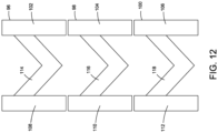
- three stabilization devices 96, 98, 100 are positioned such that legs 102, 104, 106 and legs 108, 110, 112 align.
- the openings in the legs align such that alignment elements can be positioned through the openings such that the alignment elements are positioned in all three stabilization devices.
- the cross-members 114, 116, 118 are aligned such that the cross-members are in the same position relative to each other along a length of the devices.
- stabilization devices can be rotated relative to each other such that the orientations of the stabilization devices from each other.
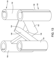
- stabilization device 120 and stabilization device 122 are offset from each other. Further, stabilization device 120 is positioned upside down relative to stabilization device 122. Center points 124, 126 of cross-members 128, 130 are positioned proximate to each other while legs 132, 134 of stabilization device 120 are offset from legs 136, 138 of stabilization device 122. Offsets can be selected based on requirements of use, anatomy of patient, geometries of the target areas, tissue type, location and/or type of injury, desired distance between the target tissue areas, desired compression, and/or needs of the surgical team.
- Methods for implanting a stabilization device can include drilling pilot holes.
- pilot holes can be drilled using a drill guide. Pilot holes can be drilled at selected locations in target tissues. Locations for the pilot holes can be selected based on type of procedure, type of injury, anatomy of the patient, needs of the surgical team, etc. Positioning an alignment element in the hole. For example, an alignment pin can be positioned in pilot holes. After positioning of the alignment elements, a cut guide can be positioned over the alignment elements. The cut guide can be used to make a cut for a cross-member of a stabilization device. A stabilization device can then be implanted. In some instances, portions of the stabilization device can engage with the alignment elements.
- the stabilization device can include additional cross-members and/or legs as necessary. Additional cross-members and/or legs can provide additional compression force or distraction force. For example, placement of alignment elements of can affect compression forces applied by the stabilization device during use. In some embodiments, multi-planar compression can be desired. Legs and/or cross-members of the stabilization devices can provide compressive load in multiple directions.
- stabilization devices can be formed such that the device can apply a selected compression load to target areas.
- a stabilization device can be positioned such that it provides a selected compression load to bones of an osteotomy or fracture.
- a stabilization device can provide fusion site compression via legs while providing bicortical locked or non-locked fixation on perimeter of the device.
- Stabilization devices can be used to apply distraction to target areas of tissue.
- Some of the surfaces of the stabilization device may include coatings and/or surfaces that are compatible with in vivo use and/or that promote bone growth.
- portions of a stabilization device can have porous or perforated structures to promote bone growth.
- Stabilization devices or portions thereof can be coated or wrapped or surfaced treated to provide bony in-growth or through-growth.
- stabilization devices or elements thereof can be formed from a material that possesses a structure conducive to bony in-growth or through-growth, such as a porous mesh, hydroxyapatite, or other porous surface.
- Stabilization devices can be covered with various other coatings such as antimicrobial, antithrombotic, and osteoinductive agents, and/or a combination thereof.
- Stabilization devices can include sections having varying wall thicknesses.
- a wall thickness 70 of leg 66 and a wall thickness 74 of cross-member 72 differs.
- Wall thicknesses of legs can be in range from about XX to XX mm and wall thicknesses of cross-members can be in range from about XX to about XX mm.
- a length 76 of cross-member 72 as shown in FIG. 7 is constant along a width of the cross-member 72. In alternate embodiments, a length of a cross-member may vary along a width of the cross-member.
- the instrumentation for implanting stabilization devices can include a drill, a cutting element such as a drill bit, burr, etc., a drill peck, a broach, a cutting guide, a tap, and/or an insert device can be useful for preparing the target area of tissue and implanting the stabilization devices.
- Stabilization devices described herein may be used in conjunction with other orthopedic devices such as screws, plates, etc. to fix and/or fuse target areas of bone.
- Positioning of stabilization devices into a target area of bone may include placing alignment elements such as guide wires into a bone piece. Alignment elements can be used to position a cutting guide. The cutting guide can be used to cut an opening in tissue for a stabilization device.
- stabilization devices can be combined with a plate suitable for attachment to bone or the like via screws.
- a stabilization device can compress target areas of bone or tissue.
- a plate structure and a stabilization device can be arranged in a side-by-side arrangement.
- a plate and fasteners used to secure the plate can be parallel to, perpendicular to, or positioned at another angle relative to a leg of the stabilization device.
- Stabilization devices can provide compression by positioning and/or structure of alignment elements, legs, and/or cross-members. Legs can have various alignments and configurations. Stabilization devices can be used to oppose bone surfaces, whether in fusion or fracture care.
- Stabilization devices can be implanted using a cutting guide.
- Cutting guides can be structured to allow for cutting of tissue positioned between alignment elements.
- cutting guides can have openings that couple to alignment elements positioned in target areas of bone.
Landscapes
- Health & Medical Sciences (AREA)
- Surgery (AREA)
- Life Sciences & Earth Sciences (AREA)
- Orthopedic Medicine & Surgery (AREA)
- Heart & Thoracic Surgery (AREA)
- Veterinary Medicine (AREA)
- Engineering & Computer Science (AREA)
- Biomedical Technology (AREA)
- Nuclear Medicine, Radiotherapy & Molecular Imaging (AREA)
- Medical Informatics (AREA)
- Molecular Biology (AREA)
- Animal Behavior & Ethology (AREA)
- General Health & Medical Sciences (AREA)
- Public Health (AREA)
- Rheumatology (AREA)
- Neurology (AREA)
- Surgical Instruments (AREA)
- Prostheses (AREA)
Applications Claiming Priority (2)
| Application Number | Priority Date | Filing Date | Title |
|---|---|---|---|
| US202163265198P | 2021-12-10 | 2021-12-10 | |
| US18/048,896 US12616464B2 (en) | 2021-12-10 | 2022-10-24 | Stabilization devices |
Publications (2)
| Publication Number | Publication Date |
|---|---|
| EP4193941A2 true EP4193941A2 (fr) | 2023-06-14 |
| EP4193941A3 EP4193941A3 (fr) | 2023-08-16 |
Family
ID=83996257
Family Applications (1)
| Application Number | Title | Priority Date | Filing Date |
|---|---|---|---|
| EP22203686.5A Pending EP4193941A3 (fr) | 2021-12-10 | 2022-10-25 | Dispositifs de stabilisation |
Country Status (2)
| Country | Link |
|---|---|
| US (1) | US12616464B2 (fr) |
| EP (1) | EP4193941A3 (fr) |
Family Cites Families (17)
| Publication number | Priority date | Publication date | Assignee | Title |
|---|---|---|---|---|
| US4741336A (en) * | 1984-07-16 | 1988-05-03 | Ethicon, Inc. | Shaped staples and slotted receivers (case VII) |
| US6554852B1 (en) | 1999-08-25 | 2003-04-29 | Michael A. Oberlander | Multi-anchor suture |
| US20070156241A1 (en) | 2004-08-09 | 2007-07-05 | Reiley Mark A | Systems and methods for the fixation or fusion of bone |
| EP1764042A3 (fr) | 2005-09-12 | 2009-08-26 | Arthrex, Inc. | Agrafe à compression |
| US8679123B2 (en) * | 2008-11-20 | 2014-03-25 | Mbrace, Llc | Surgical device, system and method of use thereof |
| US9254130B2 (en) | 2011-11-01 | 2016-02-09 | Hyun Bae | Blade anchor systems for bone fusion |
| US9615856B2 (en) | 2011-11-01 | 2017-04-11 | Imds Llc | Sacroiliac fusion cage |
| US10238382B2 (en) | 2012-03-26 | 2019-03-26 | Engage Medical Holdings, Llc | Blade anchor for foot and ankle |
| FR2999069B1 (fr) | 2012-12-06 | 2016-03-11 | In2Bones | Agrafe de compression a jambes convergentes |
| EP3145422B1 (fr) * | 2014-05-21 | 2021-01-06 | Zimmer, Inc. | Agrafes |
| US20170202552A1 (en) * | 2014-07-10 | 2017-07-20 | Crossroads Extremity Systems, Llc | Bone implant with anti-rotation |
| US10285689B2 (en) | 2015-01-07 | 2019-05-14 | Biomet C.V. | Orthopedic implant for bone fixation |
| US10376367B2 (en) | 2015-07-02 | 2019-08-13 | First Ray, LLC | Orthopedic fasteners, instruments and methods |
| US10779816B2 (en) * | 2016-07-07 | 2020-09-22 | Medline Industries, Inc. | Orthopedic implant, method, and kit |
| WO2018148284A1 (fr) | 2017-02-07 | 2018-08-16 | Crossroads Extremity Systems, Llc | Implant à contre-couple |
| USD870284S1 (en) | 2017-07-31 | 2019-12-17 | Crossroads Extremity Systems, Llc | Osteosynthesis clip |
| US20220008106A1 (en) | 2018-12-27 | 2022-01-13 | Wright Medical Technology, Inc. | Bone fixation implants |
-
2022
- 2022-10-24 US US18/048,896 patent/US12616464B2/en active Active
- 2022-10-25 EP EP22203686.5A patent/EP4193941A3/fr active Pending
Also Published As
| Publication number | Publication date |
|---|---|
| US20230181184A1 (en) | 2023-06-15 |
| EP4193941A3 (fr) | 2023-08-16 |
| US12616464B2 (en) | 2026-05-05 |
Similar Documents
| Publication | Publication Date | Title |
|---|---|---|
| AU2013260048B2 (en) | Porous spacers, instruments, and methods for foot and ankle fusion | |
| EP3166505B1 (fr) | Implant osseux anti-rotation | |
| US9861404B2 (en) | Devices, systems and methods for re-alignment of bone | |
| JP4851329B2 (ja) | 椎間関節置換 | |
| EP2623044B1 (fr) | Bloc coupant chirurgical | |
| EP3242610B1 (fr) | Implant orthopedique pour fixation d'os | |
| CA2967478C (fr) | Technique et systeme de cheville intra-medullaire | |
| AU2019395318A1 (en) | Resection guides, sweeping reamers, and methods for use in total ankle replacement | |
| EP1718223B1 (fr) | Clou centromedullaire | |
| EP3062718B1 (fr) | Implant d'ostéotomie | |
| EP4023179B1 (fr) | Système comprenant une structure en mousse et un dispositif de fixation chirurgical | |
| KR102566656B1 (ko) | 플랫폼 골절 고정 임플란트 | |
| EP4132395B1 (fr) | Système de placage osseux quadrilatéral suprapectinal | |
| WO2018023131A1 (fr) | Dispositif de fixation osseuse et procédé d'utilisation. | |
| US20210346075A1 (en) | A femoral nail and instrumentation system | |
| CA2960304C (fr) | Ensemble plaque-lame d'osteotomie femorale proximale modulaire et methode de fixation associee | |
| AU2023472576A1 (en) | Bony fusion implant, insertion instrument, and methods | |
| US12167873B2 (en) | Spinal fixation assembly | |
| US12616464B2 (en) | Stabilization devices | |
| US11918263B2 (en) | Mixed materials bone screw | |
| US12108970B2 (en) | System and method for facilitating osteotomy of the pelvic | |
| US12629184B2 (en) | Dynamic nail-plate combination | |
| US20240081881A1 (en) | Dynamic Nail-Plate Combination | |
| CA2529119A1 (fr) | Pinces orthopediques |
Legal Events
| Date | Code | Title | Description |
|---|---|---|---|
| PUAI | Public reference made under article 153(3) epc to a published international application that has entered the european phase |
Free format text: ORIGINAL CODE: 0009012 |
|
| STAA | Information on the status of an ep patent application or granted ep patent |
Free format text: STATUS: REQUEST FOR EXAMINATION WAS MADE |
|
| 17P | Request for examination filed |
Effective date: 20221025 |
|
| AK | Designated contracting states |
Kind code of ref document: A2 Designated state(s): AL AT BE BG CH CY CZ DE DK EE ES FI FR GB GR HR HU IE IS IT LI LT LU LV MC ME MK MT NL NO PL PT RO RS SE SI SK SM TR |
|
| PUAL | Search report despatched |
Free format text: ORIGINAL CODE: 0009013 |
|
| AK | Designated contracting states |
Kind code of ref document: A3 Designated state(s): AL AT BE BG CH CY CZ DE DK EE ES FI FR GB GR HR HU IE IS IT LI LT LU LV MC ME MK MT NL NO PL PT RO RS SE SI SK SM TR |
|
| RIC1 | Information provided on ipc code assigned before grant |
Ipc: A61B 17/064 20060101ALI20230710BHEP Ipc: A61B 17/68 20060101AFI20230710BHEP |
|
| P01 | Opt-out of the competence of the unified patent court (upc) registered |
Effective date: 20230822 |
|
| RBV | Designated contracting states (corrected) |
Designated state(s): AL AT BE BG CH CY CZ DE DK EE ES FI FR GB GR HR HU IE IS IT LI LT LU LV MC ME MK MT NL NO PL PT RO RS SE SI SK SM TR |