EP4194154A1 - Système de programmation de robot - Google Patents
Système de programmation de robot Download PDFInfo
- Publication number
- EP4194154A1 EP4194154A1 EP22211297.1A EP22211297A EP4194154A1 EP 4194154 A1 EP4194154 A1 EP 4194154A1 EP 22211297 A EP22211297 A EP 22211297A EP 4194154 A1 EP4194154 A1 EP 4194154A1
- Authority
- EP
- European Patent Office
- Prior art keywords
- dummy
- dummy device
- orientation
- cameras
- tool
- Prior art date
- Legal status (The legal status is an assumption and is not a legal conclusion. Google has not performed a legal analysis and makes no representation as to the accuracy of the status listed.)
- Pending
Links
Images




Classifications
-
- B—PERFORMING OPERATIONS; TRANSPORTING
- B25—HAND TOOLS; PORTABLE POWER-DRIVEN TOOLS; MANIPULATORS
- B25J—MANIPULATORS; CHAMBERS PROVIDED WITH MANIPULATION DEVICES
- B25J9/00—Program-controlled manipulators
- B25J9/16—Program controls
- B25J9/1656—Program controls characterised by programming, planning systems for manipulators
-
- G—PHYSICS
- G05—CONTROLLING; REGULATING
- G05B—CONTROL OR REGULATING SYSTEMS IN GENERAL; FUNCTIONAL ELEMENTS OF SUCH SYSTEMS; MONITORING OR TESTING ARRANGEMENTS FOR SUCH SYSTEMS OR ELEMENTS
- G05B19/00—Program-control systems
- G05B19/02—Program-control systems electric
- G05B19/42—Recording and playback systems, i.e. in which the program is recorded from a cycle of operations, e.g. the cycle of operations being manually controlled, after which this record is played back on the same machine
-
- G—PHYSICS
- G05—CONTROLLING; REGULATING
- G05B—CONTROL OR REGULATING SYSTEMS IN GENERAL; FUNCTIONAL ELEMENTS OF SUCH SYSTEMS; MONITORING OR TESTING ARRANGEMENTS FOR SUCH SYSTEMS OR ELEMENTS
- G05B2219/00—Program-control systems
- G05B2219/30—Nc systems
- G05B2219/36—Nc in input of data, input key till input tape
- G05B2219/36451—Handheld toollike probe, work instructor, lightweigted, connected to recorder
-
- G—PHYSICS
- G05—CONTROLLING; REGULATING
- G05B—CONTROL OR REGULATING SYSTEMS IN GENERAL; FUNCTIONAL ELEMENTS OF SUCH SYSTEMS; MONITORING OR TESTING ARRANGEMENTS FOR SUCH SYSTEMS OR ELEMENTS
- G05B2219/00—Program-control systems
- G05B2219/30—Nc systems
- G05B2219/36—Nc in input of data, input key till input tape
- G05B2219/36452—Touch points with handheld probe, camera detects position and orientation probe
-
- G—PHYSICS
- G05—CONTROLLING; REGULATING
- G05B—CONTROL OR REGULATING SYSTEMS IN GENERAL; FUNCTIONAL ELEMENTS OF SUCH SYSTEMS; MONITORING OR TESTING ARRANGEMENTS FOR SUCH SYSTEMS OR ELEMENTS
- G05B2219/00—Program-control systems
- G05B2219/30—Nc systems
- G05B2219/36—Nc in input of data, input key till input tape
- G05B2219/36453—Handheld tool like probe
Definitions
- the present invention belongs to the field of industrial robots, in particular of automatic programming of industrial robots by means of an industrial programming system.
- the present invention also relates to a method of industrial robot programming by means of the aforementioned industrial programming system.
- the present invention is also related to a computer program which carries out the method for the industrial programming.
- industrial robots are systems which provide advanced tools or devices, operated by means of software, which achieve flexibility and adaptability of production. This is essential for enterprises of all sizes to survive in global competition. Thus, industrial robots are seen as a key element in flexible manufacturing systems.
- the overall controlling software is particular for each industrial robot, and often cannot be accessed by the user, which is then biased to the programming functions provided by the user manufacturer. This is not ideal if tweaks are required to adapt it to changing requirements, particularly for including advanced, not yet encoded, manufacturing methods for additional products, especially when single part production is going to be done.
- OLP shifts the burden of robot programming from the robot operators jogging robot manipulator in the workshop to the software engineers, who 'jog' a simulated robot in a computer-modelled environment.
- OLP provides advantages such as reusable code, flexibility for modification, and less system downtime during programming stage. However, the time and cost required to generate code for a complex robotic system using OLP is expected to be similar to if not more than that using online programming.
- the patent application CN 110 039 523 A discloses an industrial robot vision's servosystem for path planning in a welding automated system, which comprises infrared laser positioning.
- the present systems and methods produce high resolution acquisition that is still not sufficient for welding or AM operations, requiring an accuracy ⁇ 0.2 mm.
- accuracy can be provided by these tracking systems, which lack the ability to define the geometries of the components and therefore require a preliminary programming of the robot along the nominal weld path. This operation can be very complex in the case of three-dimensional and non-linear paths.
- the present invention provides a solution for the aforementioned problems, by an industrial robot programming system according to claim 1, a method for the programming of an industrial robot programming system according to claim 11, a computer program according to claim 22 and a computer-readable data carrier according to claim 23.
- an industrial robot programming system according to claim 1 a method for the programming of an industrial robot programming system according to claim 11
- a computer program according to claim 22 a computer-readable data carrier according to claim 23.
- the invention provides an industrial robot programming system for the programming of an industrial robot, characterized in that it comprises:
- a “dummy tool” or equivalently a “dummy device” would refer to a non-functional tool but substantially identical to a “real tool” or “real device” (fully functional tool) in shape and which, from the operational and handling perspective, similar to a real tool for its use by a user.
- the dummy device is configured to be actuated by a user in the same way as a real tool, for instance, via a trigger, button or commands.
- the dummy device would be a torch mimicking the real welding torch from the operational perspective (i.e., the user uses both of them in the same way, pressing the same buttons or providing the same commands) but certain elements, either dangerous or expensive, are missing (e.g., the electric arc or the welding power supply if the dummy tool mimics a welding torch, or the paint depot if the dummy tool corresponds to a simulated paintbrush).
- the dummy tool is manufactured by means of 3D additive printing (e.g., by using polylactic acid, Nylon, thermoplastic elastomer, etc.), which lowers the costs and provides for a reduced weight of the dummy device.
- an "operative mode” will be understood as the mode in which the whole industrial programming system performs the simulation of several operations for achieving a particular result while the operations are captured in order to determine the operations that the real tool will carry out during the manufacturing process.
- the term "operations” will be interpreted as those actions carried out by the real tool or the dummy tool if they are simultated, at least comprising the movement defined at least by the trajectory of the tool and, optionally by the orientation of the tool. Further optional actions of the operations are triggering events, or actions executed by the assistance of buttons or triggers.
- the operative mode does not imply actually performing the real manufacturing process, but a simulation thereof.
- such simulated operations are related with the welding of several parts by means of any welding process, as well as with any coupling process or manufacturing process.
- the simulated operations of the operative mode involve cutting, mechanizing or other industrial manufacturing processes such as cutting, joining, coating, welding, deburring, milling, grinding, polishing, milling, drilling, mounting or painting.
- the operative mode comprises the simulation of any required procedure which is to be performed by a real industrial robot in the industrial environment which allows achieving any manufacturing process.
- the required procedures comprise movements of the dummy tool that must be captured and reproduced later when the industrial process is carried out by an industrial robot.
- the dummy tool movements are defined by a path of a reference point of the dummy device and the orientation adopted by the dummy device.
- the dummy tool movements learned during the operative mode serve as a training. Then, said movements are suitable for being reproduced by the industrial robot during a manufacturing mode, in which said industrial robot performs the real manufacturing process (like cutting, joining, coiting, etc.) with a real tool.
- the "scene” would refer to a scenario in which the operation with the dummy device takes place, like an industrial plant or a room.
- the scene comprises at least a fixed calibration reference (further referred to "second reference means", like a static object or point in the scene) which serves to establish a position reference for the trajectory and orientation of the dummy device.
- second reference means like a static object or point in the scene
- the scene could be recorded by an imaging acquisition means (as it will be explained later) and said second reference means must be present, at least, in an image recorded by said imaging acquisition means.
- One of the main objectives of the system of the invention is to provide the position and/or the orientation of the dummy device with regard to said second reference means during the entire manufacturing or industrial process.
- the system of the invention comprises a dummy device.
- a dummy device refers to a non-functional device which is handled by a user (either a human or robotic user) in the same way as a real tool would be handled in an industrial or manufacturing process during real manufacturing mode.
- a system provides guided programming of industrial or manufacturing processes such as welding, deburring, milling, grinding, polishing, milling, drilling, mounting or painting.
- an "industrial” or “manufacturing” process would be understood in the broad sense, comprising any process performed by industrial machinery in any type of industry (automotive, construction, metal production, mining, agriculture, chemical, etc.), especially when repetitive actions need to be executed.
- an "industrial robot" programmed by the system of the invention can be any electromechanic device or machinery of any of this industries (e.g., a robotic arm, etc.).
- the collected data are structured as "time frame records", such that each record comprises information about the position and/or orientation of at least one sensor of the dummy device.
- the time information can be labelled as a timestamp or the like.
- the collected data only refer to information about a starting position of the dummy device.
- said dummy devices travels a certain path and, for each point of said path, a record is collected.
- a sequence of time frame records obtained by means of the sampled location points and/or orientations of the device defines a relevant "path", thus the path being obtained from the sampling of the at least one sensor, capturing the data coming from the device.
- This path is representative of the operation of the user during the operative mode.
- the invention is intended to optimize the trajectories or as an automated trajectory planner in an industrial environment.
- the invention is able to collect data of the orientation/position of the dummy device while performing a certain industrial task, store said data and process them to optimize the trajectory (either simplifying it or adjusting it depending on the resolution to be achieved in the industrial process); and finally, using the optimized trajectory to program an industrial robot.
- the collected data define a trajectory suitable for the industrial robot.
- to program the industrial robot must be interpreted as uploading or transferring a set of instructions to said industrial robot, such that the industrial robot reproduces the trajectory defined by the collected data or, by the any optimized data.
- the industrial robot receives the instructions, it enters into the manufacturing mode, in which it reproduces the trajectory that it has been instructed to.
- the transfer of instructions to program the industrial robot is carried out wirelessly or, alternatively, by transferring the instructions using a data connector (USB cable or the like).
- the instructions can be stored in the storage means of the system according to a preferred embodiment of the present invention before being transferred to the industrial robot.
- Said device embodied as a dummy tool, is not necessarily directly coupled with any additional element but to the user which is performing the manufacturing process by means of such device.
- the dummy tool comprises at least a reference location which a characteristic point that serves as a positioning and/orientation reference.
- the at least reference location is a tip of said dummy tool; whereas in other embodiments the reference location is the centroid of physical targets of the dummy tool.
- tracking at least a reference location of the dummy tool allows monitoring the industrial manufacturing process (like welding, painting, etc.) with high accuracy, as the actuation/operation of the user is represented by the variation of the position of said reference location of the dummy tool within the scene during the manufacturing process. For instance, if the manufacturing process involves painting the body of a vehicle, the collection of the position data of the tip during the entire process would provide useful information to monitor the procedure. In some specific processes the residence time of the tool in a certain position or the velocity of tool movement are important aspects to be captured from the dummy tool movement.
- the user when dealing with a welding process, the user handles a dummy welding tool and performs a simulation of the welding of two or more parts during operative mode by means of the dummy welding tool.
- the dummy device corresponds with a reproduction of a real welding tool and the operative mode would comprise the movements of the dummy tool simulating those welding tool movements which must be carried out by the real welding tool during the real welding process.
- the use of the dummy tool and mimicking the operation of a real tool used in a real manufacturing process avoids the user to perform the real manufacturing process, and thus enhances safety of the user which reproduces the manufacturing process without the need of really performing it.
- Such a manufacturing process is performed by the system of the first inventive aspect, which avoids any injuries to the users as well as removing the need of use of complicated individual protection equipment for such user, due to the fact that the manufacturing process is performed by the system of the first inventive aspect itself.
- the present industrial programming system provides a collaborative robotics, for large robots and manufacturing processes that are not very ergonomic or that present potential health problems, and is able to be customized for every industrial process need.
- the dummy device or dummy tool can be a reproduction of the tool required by the user in the manufacturing process, with a reduced weight or complexity.
- providing a dummy tool which is an exact reproduction of a real one allows the user to perform exactly the same movements and/or events as performed in a real manufacturing process. This enhances the efficiency of the system and the collected data, which can be afterwards reproduced by an industrial robot.
- this dummy tool enables that the calibration of the industrial robot takes place without wasting resources (welding material, paint, etc.).
- the industrial robot programming system comprises at least one sensor.
- Such at least one sensor can be located on the dummy device, in order to be able to provide data of its position and/or orientation, or in a different point of the system which allows the recognition of such position and/or orientation of the dummy device.
- the system is able to locate, by means of the at least one sensor, the exact position and orientation of the dummy device within the scene, handled by the user, during the whole manufacturing process. That is, when the dummy device is in its operative mode, i.e. performing a simulation of a manufacturing or an industrial process, the at least one sensor provided at the dummy device is able to locate the position and/or orientation required for the dummy device to work.
- the sensor thus performs a collection of data of the position and/or orientation of the different movements performed by the user on the dummy device during the simulated manufacturing process which corresponds with the operative mode. For instance, if the dummy device operates as a cutting device with a sharpened tip, then by tracking the position of the tip and collecting said data, the industrial process can be optimized and automated later by refining the trajectory travelled by the dummy device.
- this feature of the system allows its use for training and programming an industrial robotic system.
- Such collected data taken by means of at least one sensor, according to an embodiment is derived to the storage means by the processor, thus being sequentially stored according to the simulated manufacturing process reproduced by the dummy device, when handled by the user.
- the senor is an optical sensor (not limited to work in the visible range, but also in infrared, ultraviolet, or other frequency band).
- the dummy device comprises a sensor at every relevant scene position which provides information of the simulated manufacturing process, such as reference locations of the dummy tool which perform relevant movements, or specific locations of buttons, activation handles, etc.
- a welding tool may comprise additional sensors in the handle, the tip and/or the activation buttons in order to collect data of the position of the dummy tool, the inclination of the tip, its orientation and the time frames in which said dummy tool is activated by means of a button.
- the dummy device comprises a support portion which helps the user to maintain the tool in its proper position, as well as carrying its weight when necessary.
- the processor is configured to collect data from the at least one sensor at a predetermined time frequency.
- this provides of collected data of several relevant instants (time frames).
- such data collection allows to acquire 3D spatial positions of the dummy device with constant increments of time, and in the same way said increment will be parameterizable. Therefore, with such a data collection based on relevant time instants and spatial points, the movement speed or acceleration of the dummy device can be determined.
- the processor is further adapted to receive at least one event while collecting data in step b) and wherein the collected data are enriched with the record of the event, in particular triggering events caused by the user operating on an activation trigger and/or one or more buttons.
- the dummy device comprises 3 to 6 degrees of freedom.
- the processor is further configured to read an event occurred during the simulated operation (like the actuation of the user on a certain activation trigger and/or one or more buttons of the dummy tool) and to store it in the storage means.
- Such an event corresponds to any relevant milestone of a simulated manufacturing process, i.e. the activation and/or deactivation of the dummy device, a stop during the operative mode or a particular movement of the dummy device.
- the identification and storage of several events which occur during the manufacturing process provides a more accurate programming of the manufacturing process.
- the processor is configured to collect the data in real time.
- the processor is configured to collect the data in real time.
- this provides a reproduction of the device and of the system during the operative mode which corresponds to a simulation of a real manufacturing process, that is, the complete geometric information (position, orientation, etc.) of the dummy device during the manufacturing process is achieved.
- the collection of data in real time thus allows the simulation of a manufacturing process under real circumstances which provides of an accurate and efficient learning process, "learning" in the sense of collecting data and determining the processes to be implemented in a robot in a manufacturing system, in particular the trajectories with the appropriate orientations to be adopted.
- the processor is further configured to process the collected data.
- this provides an enhanced collection and storage of the collected data, which further provides a more accurate simulation of the manufacturing process.
- system further comprises filters which reduce the perturbances and/or the collected data.
- these filters serve for removing artifacts from the collected data of the at least one sensor, like environmental vibrations or the possible tremor that the user may have at the time of data collection.
- the use of these filters enhances the accuracy of the sensors for the collection of data, as well as it provides a greater robustness against small unwanted movements.
- the filters serve for reducing the number of collected data. In this way, the industrial robot benefits from the optimized trajectory computed by the industrial programming system according to the invention; namely, with a reduced number of points and with a lower complexity, thus it requires less storage memory and can be processed more efficiently.
- the at least one sensor of the dummy device comprises first reference means disposed on a marked area of the dummy device.
- the "first reference means" would be understood as visual means placed in the dummy tool and which are designed to be recognized by a sensor.
- the first reference means comprise 3D physical targets for artificial vision tracking or fiducial markers.
- system further comprises at least one second reference means in a fixed position in the scene.
- the "second reference means" would be understood as visual means placed in the scene (and not in the dummy tool).
- the second reference means are also designed to be easily recognized by a part of a sensor, for instance a camera with a tracking system, and serves to establish a spatial reference for measuring distances and position of different objects in the scene. This second reference is relevant when calibrating the system.
- first and second reference means are elements embodied as reference marks and/or as solid reference elements or a combination thereof, which provide the sensor with the mentioned reference for identifying the required position/orientation.
- system further comprises a plurality of cameras, each of said cameras being configured to acquire a plurality of images of the scene from a different point of view; said images comprising one or more of the first reference means and/or the second reference means; and wherein the cameras are synchronized by the processor.
- the tracking of the dummy tool can be performed.
- the image acquisition means are "synchronized" insofar as all of them, collect images of different points of view of the scene at the same time frame.
- the cameras performs the reading of several reference means, either disposed on a reference/marked area of the dummy device (first reference means) and/or relevant points of the scene (second reference means) or in the path travelled by the dummy device.
- this provides points in which the at least one sensor performs the collection of data.
- Such reference means provide a particular point/instant in which the collection of data of the position/orientation of the device is required.
- the first reference means of the system comprise one or more fiducial markers.
- fiducial markers would be understood as any visible object or marker placed within the field of view of the scene acquired by the imaging acquisition means which serves for defining a reference and measurement point in a scene.
- the fiducial markers can be applied for measuring distances in the scene, as they comprise information for identifying the positioning and/or orientation of said fiducial markers with regard to the scene.
- Examples of fiducial markers are an object placed into the scene, or a set of marks in the reticle of an optical instrument used to collect images of said scene.
- the fiducial markers are binary square fiducial markers, and more preferably, ArUco Markers.
- fiducial markers suitable for the deployment of the present invention are QR codes, barcodes, etc.
- the fiducial markers are binary square fiducial markers, and more preferably, ArUco markers.
- ArUco markers are synthetic markers comprising a black border and an inner binary matrix encoding an identifier.
- the black border facilitates a fast detection in the image while the binary matrix provides with a quick identification of the marker.
- the identifier may encode different information, in this case identifying the specific fiducial marker being captured.
- the inner binary matrix allows, in addition to providing the identification, to determine the orientation of the square uniquely.
- the distorted view of the square in a captured image in the form of a four-sided polygon makes it possible to determine its position and orientation in space and, in this way, also the position and orientation of the dummy tool on which the fiducial marker is located.
- the black border also allows to determine the three-dimensional (3D) positioning and orientation of the fiducial marker and, therefore, also the three-dimensional positioning and orientation of the tool (e.g., 3D Cartesian coordinates X, Y and Z along with information about the rotation about said axes, further referred to as "rotX”, “rotY” and “rotZ”, respectively).
- 3D Cartesian coordinates X, Y and Z along with information about the rotation about said axes
- the 3D position would refer to positioning (X, Y, Z) information.
- 6 degree of freedom (DoF) information would comprise the 3D position information enriched with rotation information (rotX, rotY, rotZ).
- the coordinates refer to a Cartesian system, equivalent reference systems can be applied instead.
- the fiducial markers can be printed onto a surface of the dummy tool, like the handler.
- the first reference means comprises at least three physical targets for artificial vision tracking located on the dummy device
- the cameras comprise at least two synchronized cameras configured for acquiring images of the scene from at least two different points of view.
- the condition of being synchronized boards should be interpreted as that they capture images at the same instant of time and therefore the information they show from different points of view correspond to the same position and orientation of the dummy tool, which allows their information to be combined.
- a 3D "physical target” would be understood as a feature or any element suitable for artificial vision (AV) tracking.
- the physical target can be an element of any geometrical shape (cube, sphere, etc.) or exhibiting a characteristic colour to ease its identification by means of AV algorithms.
- RGB camera/value would be equivalent to a general “color camera/value”.
- the color information may be encoded in red-bluegreen (RGB) space or other different color spaces (like HSL, representing Hue, Saturation and Lightness).
- the first reference means comprises at least three physical targets for artificial vision tracking attached to the dummy device
- the imaging acquisition means comprise at least two synchronized cameras configured for acquiring images of the scene from at least two different points of view.
- each of the at least three physical targets have a different RGB value allowing to identify each physical target, and wherein the cameras comprise at least two synchronized RGB cameras.
- the identification of the three physical targets makes it possible to determine a reference point of each of them, for example their centroid.
- the color of each fiducial marker makes it possible to distinguish to which physical target each reference point is associated and, in this way, with the three identified points it is possible to orient the dummy tool to which they are engaged.
- a second inventive aspect of the present invention refers to an industrial robot programming method for the programming of an industrial robot programming system, the system comprising:
- the collected data are stored in a predetermined database, thus enabling the storage of different manufacturing processes or steps.
- the method further comprises the step of storing in the storage means the processed data of step b).
- said method further comprises receiving at least one event while collecting data in step b) and wherein the collected data are enriched with the record of the event, in particular triggering events caused by the user operating on an activation trigger and/or one or more buttons.
- step b) the collected data are acquired by a continuous tracking of the position and/or orientation of the dummy device.
- the continuous tracking is a real time continuous tracking sampling the position and/orientation at predetermined time instants, for instance according to a sample rate. This provides the required data according to a real-time performance by the user of the determined manufacturing process, which is reproduced by means of the dummy device.
- the system further comprises plurality of cameras, each of said cameras being configured to acquire a plurality of images of the scene from a different point of view; said images comprising one or more of the first reference means and/or the second reference means; and wherein the cameras are synchronized by the processor.
- the first reference means comprise one or more fiducial markers and, according to another embodiment the first reference means comprises at least three physical targets for artificial vision tracking located on the dummy device, and wherein the cameras comprise at least two synchronized cameras configured for acquiring images of the scene from at least two different points of view.
- collecting data comprises the realization of the following steps for each time frame:
- the "numerical model" of the dummy device would refer to a numerical representation of predetermined three-dimensional (3D) element used as a reference means and its properties, like shape, color, dimensions and/or contours (either fiducial markers or physical targets) comprised in said dummy device, position of one or more reference locations of the dummy device (e.g., a tip or an reference location of the dummy device).
- the numerical model of the dummy device also provides information about the distance among the different reference means (physical targets, fiducial markers, etc.) of said dummy device and also the distance between each of each reference means and, at least, a reference location of the dummy device.
- the numerical model is a representation appropriate for its storage and processing by the processor or other computerized means. In this way, the numerical model comprise information about all the reference means (first and second reference means) and the essential information about the dummy device.
- the "reference location” refers to a characteristic point of the reference means (either first or second reference means), which is used as a reference for describing at least its position.
- the reference location is a centroid of the reference frame or a centroid of a collected image of the physical target.
- the orientation of the dummy device is determined by means of a triangulation algorithm using at least three different reference locations of the at least three 3D physical targets determined by at least two images of the same time frame.
- the "reference frame" of the fiducial marker would be understood as a contour or a box surrounding said fiducial marker and determining its outer shape.
- the reference frame is just a contour box encompassing the fiducial marker.
- the orientation of the reference frame can also being determined from the fiducial marker since its content allows to identify the fiducial marker and also the orientation.
- the reference location of one first reference means being estimated by two or more images is determined as a weighted average process wherein the weighting factors associated to reference locations with larger size of the first reference means shown in the image have higher values. That is, from each of the cameras where the first reference means appears, its position is estimated. The position will have different errors for the estimation obtained from each of the cameras. The position is calculated as the weighted average of the estimated positions, establishing a higher weight to those positions that are closer to the corresponding camera and where the markers appear with a larger size.
- a different 6 DoF position of the dummy device is computed for each of them.
- a unique coordinate system that is to say, a unique 6 DoF position
- their contribution also needs to be averaged, in order to decrease the positioning and orientation error.
- the multiple reference location involve acquiring redundant information to overcome the problem of occlusion typical of object tracking.
- the weighting factor associated to reference locations with a reference frame less distorted in the image have higher values.
- the distortion (or transformation) in the image is measured by using any known shape-based matching algorithm, comparing the 3D numerical model of the reference means (ideal representation of the shape and color information) and how said reference means appear in the image.
- the matching algorithm assigns a weighting factor (also referred to as "score") depending on the similarity between the reference means image (e.g., a physical target image) and the ideal reference means (given by the 3D numerical model).
- Other suitable distortion measurements are cross-correlation, sum square difference or any known image descriptor known by the expert in the field (like scale-invariant feature transform, SIFT, etc.).
- the shape-based matching algorithm works as follows: the ideal 3D numerical model is iteratively transformed (translated, rotated, etc.) until it matches with the first reference means in a collected image. Once there is a match, said transformation (rotation, translation) is the one that has undergone the dummy tool. In this way, the method of the invention allows the assessment of the positioning and orientation of the dummy tool during a manufacturing process.
- the weighting factor is normalized to the range 0-1, wherein 1 corresponds to a perfect matching between the collected image of the reference means and the ideal reference means according to the numerical model (perfect agreement between the reference means as collected in an image and the ideal reference means).
- the score can be assigned by other criteria predetermined by a skilled person. Note that the shape-based matching algorithm sensitive to the known 3D numerical model of the reference means, such that it is adapted to find the features of said numerical model (shape, color, etc.) in the acquired images of the scene.
- the same first reference means is acquired in two different images of the scene, being one of them much larger than the other one in the images.
- an embodiment of the method of the present invention would not assign a normalized score of 0.5 to each of them, because the larger first reference means would serve as a more accurate 6 DoF position.
- a possible 6 DoF position of the dummy tool can be derived from each of these first reference means.
- both positions are averaged taking into account that the larger first reference means is more reliable than the smaller one.
- a possible weighting factor assignment would be 0.7 for the 6 DoF computed from the larger first reference means image and 0.3 for the other one.
- the measurement of the distortion in the image with the method according to the second inventive step is easier, as this shape is easily distorted to become a rectangle or another parallelogram, therefore it is easy to compute which transformation (translation, rotation, etc.) has undergone.
- the weighting factor depends on a non-decreasing monotonic function proportional to the distance between the camera and the observed element.
- the first reference means are physical targets and the weighted average determining the reference location reduces the weighting factor of reference locations determined in images where the first reference means are partially shown.
- the weighting factor assigned to them is lower than if they are fully recovered. In this way, a defective acquisition of some of the physical targets does not negatively affect the accuracy in the assessment of position and orientation for the dummy tool.
- the method further comprises the following steps for reducing the amount of collected data:
- the procedure of reducing the amount of collected data is carried out by the processor of the system according to the first inventive aspect.
- the new list comprising the selected points obtained with this last embodiment of the method define a simplified path (optimized trajectory) determined according to any of the previously disclosed embodiments for the dummy tool.
- the original path may suffer from missing points (which have not been obtained from the data collected by the at least one sensor) or an excessive sampling (e.g., too many points because the user has interrupted the movement, etc.).
- an excessive sampling e.g., too many points because the user has interrupted the movement, etc.
- the previous method embodiment allows to discard points which, although being collected by the at least one sensor, are useless (e.g., no significant motion of the dummy tool happened).
- This data selection by means of the defined points of the path, provide a more accurate stored movement and thus a more accurate manufacturing process performed by the device.
- An excessive number of points can cause the robot, once programmed, to stop processing points and not advance along its path.
- the purpose of this optimization algorithm carried out by the processor of the industrial robot system is to reduce the amount of collected data, with a minimum impact on the resolution of the system.
- this algorithm for reducing the amount of collected data it is worth underlining the following:
- the method according to the second inventive aspect provide, when performed by means of a system of the first inventive aspect, the programming of an industrial robot according to a particular manufacturing process, which may afterwards be reproduced in a repetitive manner.
- the user provides the relevant path and/or orientation of a dummy device, i.e. the tool required for the performance of such manufacturing method.
- a dummy device i.e. the tool required for the performance of such manufacturing method.
- Such data are collected and stored by the system, which thus enables a execution of the performed manufacturing process.
- Such process may afterwards be reproduced by an industrial robot, following the stored movements and milestones of the procedure.
- This provides a robot learning system and method which allows the execution of several manufacturing processes, advantageously those which may be hazardous or difficult for a user and/or operator.
- the invention provides a computer program comprising instructions which, when the program is executed by a computer, cause such computer to carry out the steps b) and/or c) of the method of the second inventive aspect.
- Such a computer program provides the required software, achieved after the learning process performed by the system of the first inventive aspect, which allows the execution of the real manufacturing process with a real tool in a manufacturing mode, based on the learning of the dummy tool during the operative mode.
- the invention provides a computer-readable data carrier having stored thereon the computer program of the third inventive aspect.
- this provides a functional system for the reproduction of the sequential steps (path of the device) and/or milestones (any relevant aspect during the manufacturing process), thus achieving the required results without the presence of a user or operator.
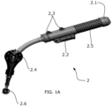
- Figures 1A-1C show different embodiments of a dummy device (2), embodied as a tool, of an industrial robot programming system (1).
- a dummy device (2) is not a real tool, although has the same constructive features whilst having a reduced weight.
- the dummy device (2) can be manufactured by additive manufacturing.
- the present dummy device (2) shown in figures 1A - 1C is a welding tool which can be handled by a user, as shown in figure 1D . Therefore, a user (U) as the one present in figure 1D is able to carry the dummy tool (2) in a real-manner simulation but is not able to actually use it.
- a dummy device (2) as the one present in figures 1A - 1C may also be embodied mimicking a real tool and thus enable the user (U) to simulate, in a very realistic way, manufacturing operations with it.
- the dummy device (2) shown in figures 1A - 1C is handled by means of a handle (2.1), which the user (U) can surround with a unique hand and carry backwards and forward, depending on the welding path which is to be followed during a simulated welding operation.
- a simulated welding operation provides the operative mode of the welding device (2) of figures 1A - 1C , as well as 1D.
- the user (U) may be human or a robotic device programmed to carry out an automated industrial procedure.
- FIG. 1A shows an activation trigger (2.2) located in the handle (2.1), actuated by the user (U) when the welding operation is to be performed.
- activation trigger (2.2) comprises two positions in the present embodiment, a first position for the activation of the welding tool and a second position for the deactivation of the welding tool (2).
- Figure 1B shows the activation trigger (2.2) embodied as a button which also comprises two different positions, the first position for the activation of the welding tool when the button is pressed and the second position for the deactivation of the welding dummy tool (2) when the button is not pressed.
- figures 1A and 1B show the handle (2.1) of the dummy device (2) further comprising a handling area (2.5) which enhances the grip to the hand of the user (U).
- a handling area (2.5) which enhances the grip to the hand of the user (U).
- such handling area (2.5) in figure 1A is embodied as a splined section
- in figure 1B it is embodied as indentations wherein several fingers of a user can be supported in order to provide a better grip of the handle (2.1).
- the dummy device (2) further comprises a tip (2.6).
- the dummy device (2) also comprises a marked area, wherein first reference means (2.4, 2.4') are provided for the at least one sensor (3) of the industrial robot programming system (1) to read.
- first reference means (2.4, 2.4') are located by means of the at least one sensor (3), and provide location and orientation data of the dummy device (2), measured by means of the predetermined distance measured at a certain direction at which the at least one sensor (3) is located.
- figure 1A shows a marked area wherein the first reference means (2.4) are embodied as reference marks, shown as several dots aligned according to several directions which help positioning the mentioned location and orientation of the tip (2.6).
- FIG. 1B Another embodiment of the dummy tool (2) with a marked area comprising first reference means (2.4, 2.4') is shown in figure 1B , wherein such marked area is embodied as a solid element (2.8) or holder, protruding from the body of the dummy tool (2).
- Such solid element (2.8) is coupled to a structure (6) with four arms, for fastening of the first reference means (2.4, 2.4').
- the structure (6) resembles a mill-like configuration, and the first reference means (2.4, 2.4') thereof help positioning the mentioned location and orientation of the tip (2.6) with an additional visual aid for the user, which can physically identify the direction/orientation of the tip (2.6) with regard to a fixed reference in the scene (second reference means).
- the marked area comprise rounded physical targets (2.4), in particular spheres, and cubic physical targets (2.4').
- other embodiments of the dummy tool (2) may comprise differently-shaped reference means (like physical targets).
- the "marked/reference area” would be understood as a region of the dummy tool (2) comprising characteristic features, like physical targets (2.4') or markers (2.4), to ease its recognition by acquiring images of the scene and applying vision-based tracking techniques.
- the solid element (2.8) or holder is attached to the rest of the dummy tool (2) by a bolted joints to allow detaching the solid element (2.8) and replacing the first reference means (2.4, 2.4') of the marked area of the dummy tool (2).
- the solid element (2.8) is integrated in the same dummy tool (2) as a single piece.
- FIG. 1C a different embodiment of the marked area comprising markers (2.4) is shown by means of two solid reference elements which are located one opposite to the other, and aligned with the tip (2.6) according to the direction in which such tip (2.6) is located. This allows the user to physically orientate the tip (2.6) according to specific requirements with a visual aid of the reference elements located in the marked area.
- the at least one sensor (3) of the industrial robot programming system (1) collects data of the milestones in which the activation trigger (2.2) or the additional buttons (2.3) are activated/deactivated in order to store information of the instants in which the tool (2) is active or performing any action.
- the at least one sensor (3) can also locate and position the tip (2.6) of the dummy device (2), and collect data during the time instants in which the dummy tool (2) is actually activated, performing a welding operation. This data, in combination with the activation of the activation trigger (2.2) or the buttons (2.3), allows storing a more accurate time frame records for the performance of the simulated welding operation.
- figure 1C shows a support portion (2.7), located adjacent to the handle (2.1) of the dummy tool (2), which helps the user to maintain the dummy tool (2) in its proper position, as well as carrying its weight when necessary.
- support portion (2.7) is supported on the chest of the user (U) and provides higher stability of the dummy tool (2) and thus a better position in its operative mode.
- the support portion (2.7) in combination with the reference elements and/or marks located at the marked area (2.4) allow the user (U) to handle the tool in a more stable and precise manner, as shown in figure 1D .
- FIG 2 shows a schematic view of an embodiment of an industrial robot programming system (1).
- the industrial robot programming system (1) comprises a sensor (3) is embodied as a laser tracker, particularly provided at the side of the structure of the system, and a camera (3.1) and provided at the top side of the mentioned structure.
- a sensor (3) is embodied as a laser tracker, particularly provided at the side of the structure of the system, and a camera (3.1) and provided at the top side of the mentioned structure.
- Such camera (3.1) and laser tracker (3) are schematically shown in figure 2 .
- the industrial robot programming system (1) comprises 6 degrees of freedom DoF (like the three Cartesian coordinates X, Y and Z; along with corresponding rotation information about each of Cartesian axes, which will be referred to as "rotX”, “rotY” and “rotZ” respectively), and is able to move and rotate in order to collect data with the aforementioned camera (3) and laser tracker (3).
- DoF degrees of freedom
- such an industrial robot programming system (1) collects data during a simulation of a manufacturing process performed as in figure 1B , wherein a user (U) handles the dummy device (2) of the shown industrial robot programming system (1).
- the user (U) of figure 1B performs, by means of the dummy device (2) of figure 1A , a simulation of the movements which would be performed by a real device in a real manufacturing process. These simulated movements are detected and stored by the industrial robot programming system (1) of figure 2 .
- the storage means (4) and the processor (5) of the industrial robot programming system (1) are schematically indicated in figure 2 , as part of the industrial robot programming system (1).
- the data collected by the sensors (3) is processed and stored by means of the processor (5) and the storage means (4).
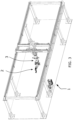
- Figure 3 shows a structure in which an alternative embodiment of an industrial robot programming system (1) is performed.
- the metallic structure of the image provides support for the installation and movement of an industrial robot (in this case, a robotic arm), which handles a dummy device (2) such as the one of figure 1A .
- sensors (3) are located along the metallic structure, which allow monitoring the robotic arm whilst a manufacturing process is performed thereof, such as a welding process by means of the robotic arm.
- the present robotic arm is able of reproducing the manufacturing process stored by the industrial robot programming system (1).
- Example 1 a particular example (Example 1) of a determined manufacturing process is hereby detailed, in order to further show the advantages of the industrial robot programming system (1) of the invention, as well as the method for programming such a system (1).
- the aluminium boat manufacturing system starts in a 3D design from which the necessary aluminum sheets to build the boat geometry are generated. Said aluminium sheets will be cut automatically, either by laser, by water jet, plasma or flame cutting. This whole process is automated.
- the dummy device (2) mimics the welding tool used by the welding operators and the system (1) provides with a simulated welding operation (trajectory, etc.) which can be performed by an industrial robot. Once the one or more industrial robots is/ are programmed, such welding operations can be run automatically without human intervention.
- the industrial robot programming system (1) When performing a simulated welding operations with such a dummy tool (2) by an operator, the industrial robot programming system (1) is able to store it in storage means (4). Then, the simulated welding operations are transferred to one or more industrial robots which reproduce them in a real welding operation in order to reduce the mentioned time-consuming process, whilst achieving a more accurate performance of the required welds.
- the geometrical information obtained by the industrial robot programming system (1) of the invention allows a digital compilation of information including the know-how of the expert operator, thus implementing a successful simulation of the welding process which can be later transferred to a real industrial robot to reproduce certain welding operations according to the instructions it has received.
- the industrial robot programming system (1) provides means able to simulate a welding process controlling and analyzing parameters as penetration, deposition rate, bead size, bead height and bead width. Once the welding process is simulated and the optimized trajectories of the dummy tool are learned by the system (1), said trajectories are sent to the industrial robot in order to reproduce them in a real welding process.
- Example 2 dummy tool (2) with fiducial markers (2.4)
- Figures 4A-4C display an embodiment of the dummy tool (2) according an industrial robot programming system (1) of the invention.
- the position and orientation of the tip (2.6) of said dummy tool (2) can be obtained thanks to a plurality of fiducial markers (2.4) which are placed in a marked area of the dummy tool (2).
- a solid element (2.8) or holder is embodied as a branch of the main body of the dummy tool (2), and serves for holding a cubic structure (6).
- a plurality of fiducial markers (2.4) are printed in the surface of said structure (6), at least in some of the faces of said structure (6).
- binary (black and white) square fiducial markers Aruco markers have been considered because they allow identification of the fiducial marker and also allows to determine position and orientation of said marker. Position by determining a reference point of the fiducial marker and the matrix also determine the orientation, in particular of each side of the frame surrounding the fiducial marker.
- Aruco markers are design to decrease the risk of misidentifying a marker for another by maximizing the distances between marker matrices.
- Each fiducial marker (2.4) matrix corresponds to a different identifier or interpretation code (in this case, a binary matrix; in other embodiments, characters or other distinguishable features) which comprises unique information for each of them. Fiducial binary identifiers that are either close to all black or close to all white are avoided, as they can be confused with other objects in the scene.
- square contours of the Aruco fiducial markers (2.4) are considered as reference frames (7), which allow easily identifying the transformation (rotation, translation, etc.) that the fiducial marker (2.4) have undergone, thus computing the position and orientation of the tool depending on the images collected of said fiducial markers (2.4) by the cameras (3.1) of the system (1). It may be highlighted that in this preferred embodiment, the square-shaped fiducial markers (2.4) simplifies the identification of the distortion. In the event of a distortion (rotation, translation of the dummy tool (2)) in the images, the collected fiducial markers (2.4) images are shown exhibiting rectangles or other parallelogram as contours. Therefore it is easy to compute which transformation in 6 DoF (translation, rotation, etc.) has undergone, by reverting it to the original shape.
- 6 DoF transformation, rotation, etc.
- a reference frame (7) is defined as the black contour of the fiducial markers (2.4) such that it allows to translate and rotate the particular 6 DoF position of the fiducial marker (2.4) to a final 6 DoF position (final coordinate system) with regard to a reference location of the dummy device (2), like the tip (2.6).
- the shape of the reference frame (7) is a square then the transformation from the 4 vertex polygon to a square is easy determining the position and orientation in space.
- the numerical model of the dummy tool (2) it is possible to compute the final 6 DoF position of the dummy tool (2) with regard to a fixed point of the scene (second reference means) since the numerical model comprises information about the shape of the dummy device (2), the position of the tip (2.6) and the position and orientation of the fiducial markers (2.4).
- the second reference means must be visible in at least some of the images of the scene, in order to establish a positioning and orientation reference between the tip (2.6) of the dummy device (2) and said second reference means.
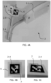
- Figure 4A comprises only a single picture of the scene as collected by a single camera (3.1) (like a monochrome camera) since a single fiducial marker (2.4) allows to determine its location and its orientation and therefore also the location and orientation of the dummy device (2).
- a plurality of images of the scene is acquired from different points of view and by using different cameras (3.1).
- the detection of fiducial markers (2.4) works with a single marker detected in at least two different cameras, it is worth underlining that by increasing the amount of fiducial markers (2.4) in the dummy tool (2) as well as by incorporating multiple cameras (3.1) in the system (1), the tracking of the dummy tool (2) is more accurate and robust against perturbances or occlusions.
- the dummy tool (2) of Figure 4A comprises a fiducial marker in each of the six faces of the structure (6) and it is preferably used in an industrial robot programming system (1) comprising multiple cameras (3.1). In that case, the different cameras are synchronized when taking images of the scene, in order to acquire different points of view of the scene at the same time frame.
- the resulting 6 DoF position (output of position and orientation of the dummy tool (2)) is more precise.
- the 6 DoF position provided by each of the fiducial markers (2.4) is averaged depending on the fiducial markers size in the image and their alignment. All this processing (including the registration of different images acquired with multiple cameras (3.1)) is performed by the processor (5) of the industrial robot programming system (1). Particularly, a shapematching algorithm is applied, as explained in connection with Figures 4B and 4C .
- a reference point is the centroid of the reference frame.
- the cameras are RGB, it is possible to use black and white cameras, although it would also work with RGB cameras.
- Figures 4B and 4C correspond to different images of fiducial markers (2.4) acquired by at least two cameras (3.1) during the operation of the user (U) with the dummy tool (2).
- the method of the invention would take into account both of them through a weighted average in order to determine the 6 DoF position of the dummy tool (2).
- Figure 4B shows a fiducial marker (2.4) which almost matches a perfect square (mainly squared-shaped reference frame (7) in the detected 2D image. Then, the centroid of the reference frame (7) detected in each image is considered as the reference location. Consequently, the method of the present invention would assign a high weighting factor due to its high degree of parallelism with the perfect shape expected for that fiducial marker (2.4) according to the ideal numerical model.
- Figure 4C shows a fiducial marker (2.4) which is mainly distorted (much rotated and which does not fit within the ideal reference frame (7) according to the numerical model), thus it is penalized in terms of weighting factor.
- the weighting factor measures the geometric similarity between the detected outline (reference frame (7)) of the fiducial marker (2.4) and the ideal shape of said reference frame (7) according to the numerical model of the fiducial marker (2.4), in this case, a perfect square. The more the marker outline resembles a perfect square, the larger weighting factor is assigned to it. Also, a larger weighting factor would be awarded to a fiducial marker (2.4) image the larger it looks in the acquired images of the scene.
- the weighting factors (score) can be a normalized value in the range 0-1.
- the sum of the weighting factors given to the images associated with the same first reference means is 1, that is, weighting factors are normalized.
- the markers from Figures 4B-4C would correspond to the same marker acquired in the same time frame available to compute the reference coordinate system, then the coordinate system determined by the marker from Figure 4B must receive a weighting factor much larger (i.e., 0.7) than the fiducial marker from Figure 4C , as the latter does not seem reliable enough.
- multiple fiducial markers (2.4) are tracked simultaneously in several images. In this way, the weighted average takes into account the size, orientation and whether the recovery of each of these fiducial markers (2.4) is complete or not in order to assign different weighting factors.
- weighting factors determine the relevance awarded to the 6 DoF position of the dummy tool (2) derived from each fiducial marker (2.4).
- the different 6 DoF positions obtained by the several fiducial markers (2.4) are computed.
- a unique 6 DoF position is assigned as the (weighted) average of the coordinate systems determined by several fiducial markers (2.4).
- the outcome of this processing is provided as a final 6 DoF position of the dummy tool (2) with regard to the fixed second reference means in the scene.
- an outcome can be the list of 6 DoF positions representing the trajectory of the dummy tool (2), or at least a reference location of it (like the tip (2.6).
- the information regarding the time frame is also embedded as a timestamp, therefore, speed of the dummy tool (2) can be computed.
- Example 3 dummy tool (2) with physical targets (color and shape physical targets)
- the dummy tool (2) is equipped with at least more than two different color physical targets. Particularly, four rounded physical targets (2.4') having different colors (red R, yellow Y, green G and blue B) are considered. Each color allows to identify each of the physical targets uniquely.
- This physical targets (2.4') are coupled to the body of the dummy tool (2) by means of a solid element (2.8) attached to a structure (6) with a plurality of arms for fastening said physical targets (2.4').
- the coupling between the dummy tool (2) and the physical targets (2.4') can be permanent or detachable (by using fastening means such as grapes, etc.), as previously explained with regard to the embodiment of Figure 1B .
- the coupling shown in Figure 5 is based on a bolted joint. A user (either human or robotic) may manipulate the dummy tool (2) handling it by means of the handler (2.1).
- the industrial robot programming system (1) comprises a plurality of RGB cameras (in this case, 4 RGB cameras such that they acquire four different perspectives of the scene in which the operation of the user (U) takes place.
- the RGB cameras are calibrated in advance (by any state of the art method) and synchronized each other and with the processor (5) of the industrial robot programing system (1). It has also been indicated that, as the physical targets (2.4') are color coded, the use of a RGB camera is essential, whereas the fiducial markers (2.4) approach is compatible with monochrome cameras.
- the operation e.g., a manufacturing process
- the user U
- the trajectory of the dummy tool (2) is obtained as a list of 6 DoF (degree of freedom) positions, which in turn refer to the 3D Cartesian coordinates as well as the rotation about each of the Cartesian axes.
- the numerical model of the dummy tool (2) is known a priori, it is sufficient to know the position of the reference locations (in this case, centroids of each physical target (2.4') to determine the 6 DoF position of the entire dummy tool (2) during the operative mode.
- the numerical model of dummy tool (2) is calibrated prior to the execution of the method of the invention, which means that the shape, dimensions and color information of the dummy tool (2) and the first reference means (2.4, 2.4') are fully characterized.
- the distance between the different physical targets (2.4') is calibrated and the distance between the cameras and the second reference means (at least, it must be known at the initial time frame), as well as the intensity RGB (color) values of the physical targets (2.4') are previously known.
- the orientation information cannot be derived from a single physical target (2.4'), due to its rounded shape.
- at least three physical targets (2.4') are required to triangulate the 6 DoF position of the dummy tool (2).
- the fourth physical target (2.4') provides redundancy to overcome eventual occlusions.
- the shape-based matching algorithm takes into account that the physical targets (2.4') illustrated in Figure 5 are spherical. In this way, the matching algorithm tries to find full circles (2D projections of the spherical physical targets (2.4') in the collected images).
- this shape-based matching algorithm (and the similarity measurement) is sensitive to the known 3D numerical model (known geometrical information) the physical target (2.4'), such that it is adapted to find them in the acquired images of the scene.
- Other suitable similarity measurements are cross-correlation, sum square difference or any known image descriptor known by the expert in the field (like scale-invariant feature transform, SIFT, sensitive to the shape).
- the physical targets (2.4') are detected in each of the images of the scene from different points of view (from different cameras), as shown in Figure 6 .
- the shape-based matching algorithm compares the detected contours of the physical targets (2.4') and matches them with the calibrated 3D numerical model, which is predetermined.
- the physical targets (2.4') are spherical, therefore they are captured in 2D images as circles.
- the rotation would not be relevant, due to symmetry of the physical targets (2.4').
- the computation of the reference locations of the dummy tool (2) comprises a weighted average of the reference locations based on multiple points of view (images).
- images the more the contours of detected physical targets (2.4') in the images resemble full circles, the largest weighting factor they are assigned. Partial circles or images where a certain physical target (2.4') does not appear receive a weighting factor penalty.
- the reference locations are computed as the centroids of each physical target (2.4').
- the weighting factors can be normalized to the range 0-1, and those incomplete physical targets (2.4') are neglected or assigned a low weighting factor (close to 0).
- the trajectory of the dummy tool (2) is obtained as a list of 6DoF positions of the reference locations, centroids of the physical targets (2.4')) labelled with their corresponding timestamp and, the orientation computed using triangulation of at least three centroids.
- the trajectory of the dummy tool (2) is recorded during the entire operation, the manufacturing or industrial process simulated by the user by means said dummy tool (2), namely during the operative mode.
- Said 6DoF positions represent the distance between reference locations of the dummy tool (2) (in this case, the centroids of each of the physical targets (2.4')) and a second reference means embedded in the scene, for instance, an object in the scene which is always present regardless the particular point of view collected by the cameras.
- occlusions may arise by using the physical targets (2.4').
- redundancy is implemented by means of multiple cameras (at least two cameras) and a larger amount of physical targets (2.4') in the dummy tool (2).
- Example 4 Processing of the collection data of position of the dummy tool (2) during the operative mode
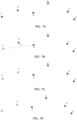
- Figures 7A-7H illustrate an example showing how the processing of the collected data of position and/or orientation of the dummy tool (2) takes place.
- the collected data correspond to the trajectory/path traveled by the dummy tool (2) when it is operated by the user (U) to carry out an industrial process.
- the point is linked to more data such as orientation (6 DoF), timestamping, or others that may enrich the amount of information related to that point.
- each point of the collected data corresponds to a 6 DoF position of the dummy device (2) at a certain time and labelled with a timestamp.
- the processing involves an optimization algorithm for reducing the amount of collected data, the optimization algorithm comprising the following steps:
- point P1 is initially marked as a selected point, light gray, and the straight line passing through P1 and P3 is computed. Then, the distance from P2 to said line is calculated (denoted as d2). In this example the straight-line or Euclidean distance is applied. Afterwards, it is checked whether d2 is larger than a threshold distance or not. If d2 ⁇ d th , then P2 is considered as a selected point and is preserved (for instance stored by the processor (5) in the storage means (4)), as shown in Figure 7C .
- FIG. 7H Another possible scenario is shown in Figure 7H , wherein simultaneously d2 ⁇ d th and d3 ⁇ d th .
- the procedure considers the following point of the collection (P5) and computes the straight line between P1 and P5.
- distances d2, d3 and d4 are calculated as the distances between intermediate points P2, P3 and P4 and the new straight line joining P1 and P5. Again, it is verified whether d4 is larger than the threshold distance or not and the procedure would continue.
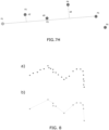
- an initially complex trajectory can be simplified to obtain a computationally more friendly version (see Figure 8B ), which eases the task of programming a robot device to reproduce it, which in turn produces other benefits such as a greater robustness against small unwanted movements (vibrations) as well as less stringent storage requirements in the robot device where the optimized trajectory instructions are loaded (such that the robot device is programmed to carried out the simplified path).
- the output is a linear piecewise approximation of the trajectory followed by the dummy tool (2).
- this new list of selected points represent with high accuracy the original path followed by the dummy tool (2) but requires less computational storage.
- Other connecting lines like splines may be used on the new reduced set of points.
Landscapes
- Engineering & Computer Science (AREA)
- Physics & Mathematics (AREA)
- General Physics & Mathematics (AREA)
- Automation & Control Theory (AREA)
- Robotics (AREA)
- Mechanical Engineering (AREA)
- Numerical Control (AREA)
Applications Claiming Priority (1)
| Application Number | Priority Date | Filing Date | Title |
|---|---|---|---|
| EP21383115 | 2021-12-07 |
Publications (1)
| Publication Number | Publication Date |
|---|---|
| EP4194154A1 true EP4194154A1 (fr) | 2023-06-14 |
Family
ID=78957326
Family Applications (1)
| Application Number | Title | Priority Date | Filing Date |
|---|---|---|---|
| EP22211297.1A Pending EP4194154A1 (fr) | 2021-12-07 | 2022-12-05 | Système de programmation de robot |
Country Status (1)
| Country | Link |
|---|---|
| EP (1) | EP4194154A1 (fr) |
Citations (4)
| Publication number | Priority date | Publication date | Assignee | Title |
|---|---|---|---|---|
| WO2011039542A1 (fr) | 2009-10-02 | 2011-04-07 | The Welding Insitute | Procédé et système de programmation d'un robot |
| CN110039523A (zh) | 2019-05-20 | 2019-07-23 | 北京无远弗届科技有限公司 | 一种工业机器人视觉伺服系统、伺服方法及装置 |
| US10913154B2 (en) * | 2018-01-02 | 2021-02-09 | General Electric Company | Systems and method for robotic learning of industrial tasks based on human demonstration |
| US20210316449A1 (en) * | 2020-04-08 | 2021-10-14 | Fanuc Corporation | Robot teaching by human demonstration |
-
2022
- 2022-12-05 EP EP22211297.1A patent/EP4194154A1/fr active Pending
Patent Citations (4)
| Publication number | Priority date | Publication date | Assignee | Title |
|---|---|---|---|---|
| WO2011039542A1 (fr) | 2009-10-02 | 2011-04-07 | The Welding Insitute | Procédé et système de programmation d'un robot |
| US10913154B2 (en) * | 2018-01-02 | 2021-02-09 | General Electric Company | Systems and method for robotic learning of industrial tasks based on human demonstration |
| CN110039523A (zh) | 2019-05-20 | 2019-07-23 | 北京无远弗届科技有限公司 | 一种工业机器人视觉伺服系统、伺服方法及装置 |
| US20210316449A1 (en) * | 2020-04-08 | 2021-10-14 | Fanuc Corporation | Robot teaching by human demonstration |
Non-Patent Citations (3)
| Title |
|---|
| "Springer Handbook of Robotics", 27 June 2016, SPRINGER INTERNATIONAL PUBLISHING, Cham, ISBN: 978-3-319-32552-1, article BILLARD AUDE G ET AL: "Chapter 74 - Learning from humans", XP055920884 * |
| ANONYMOUS: "Comparison of Fiducial Markers - Robotics Knowledgebase", 2 July 2022 (2022-07-02), XP093039257, Retrieved from the Internet <URL:https://web.archive.org/web/20220702084532/https://roboticsknowledgebase.com/wiki/sensing/fiducial-markers/> [retrieved on 20230414] * |
| ANONYMOUS: "psimpl - perpendicular distance simplification", 25 June 2018 (2018-06-25), XP093039216, Retrieved from the Internet <URL:https://web.archive.org/web/20180625185131/https://psimpl.sourceforge.net/perpendicular-distance.html> [retrieved on 20230414] * |
Similar Documents
| Publication | Publication Date | Title |
|---|---|---|
| JP7728099B2 (ja) | 人間の実演によるロボット教示 | |
| US12172303B2 (en) | Robot teaching by demonstration with visual servoing | |
| US12179350B2 (en) | Dual arm robot teaching from dual hand human demonstration | |
| US7298385B2 (en) | Method and device for visualizing computer-generated informations | |
| EP2916189B1 (fr) | Fabrication de qualité contrôlée | |
| US11247335B2 (en) | Semi-autonomous robot path planning | |
| US10664996B2 (en) | Method and apparatus for the start-up operation of a multi-axis system | |
| KR20250003819A (ko) | 자율 조립 로봇들 | |
| US20200246974A1 (en) | Handling assembly comprising a handling device for carrying out at least one work step, method, and computer program | |
| US20220168902A1 (en) | Method And Control Arrangement For Determining A Relation Between A Robot Coordinate System And A Movable Apparatus Coordinate System | |
| US10482589B2 (en) | Method and apparatus for the start-up operation of a multi-axis system | |
| Zhou et al. | Teaching robots to weld by leveraging human expertise | |
| EP4194154A1 (fr) | Système de programmation de robot | |
| JP7669231B2 (ja) | 実演による教示における両手検出 | |
| JPH1063324A (ja) | 画像入力型ロボットシステム | |
| CN115972191A (zh) | 根据双手人类演示的双臂机器人教导 | |
| Luo et al. | Robotic conveyor tracking with dynamic object fetching for industrial automation | |
| Ng et al. | Intuitive robot tool path teaching using laser and camera in augmented reality environment | |
| Moyo et al. | Enhancing manipulator flexibility: Real-time positional control for variable assembly environments using apriltag markers and edge detection | |
| Eissa et al. | An effective programming by demonstration method for smes’ industrial robots | |
| Alzarok et al. | Review for the current performances for Machine Visions in Industrial Robotic welding and drilling tasks | |
| Blessing et al. | Vision-based handling with a mobile robot | |
| Wang et al. | State Representation Learning for Visual Servo Control | |
| KR20260004866A (ko) | 디지털 트윈을 이용한 로봇 팔 원격교시 시스템 | |
| Nakamura et al. | Trajectory Planning and Control of a Robotic Manipulator Using Image Processing and ArUco Markers for Pick and Place Tasks |
Legal Events
| Date | Code | Title | Description |
|---|---|---|---|
| PUAI | Public reference made under article 153(3) epc to a published international application that has entered the european phase |
Free format text: ORIGINAL CODE: 0009012 |
|
| STAA | Information on the status of an ep patent application or granted ep patent |
Free format text: STATUS: THE APPLICATION HAS BEEN PUBLISHED |
|
| AK | Designated contracting states |
Kind code of ref document: A1 Designated state(s): AL AT BE BG CH CY CZ DE DK EE ES FI FR GB GR HR HU IE IS IT LI LT LU LV MC ME MK MT NL NO PL PT RO RS SE SI SK SM TR |
|
| STAA | Information on the status of an ep patent application or granted ep patent |
Free format text: STATUS: REQUEST FOR EXAMINATION WAS MADE |
|
| 17P | Request for examination filed |
Effective date: 20231205 |
|
| RBV | Designated contracting states (corrected) |
Designated state(s): AL AT BE BG CH CY CZ DE DK EE ES FI FR GB GR HR HU IE IS IT LI LT LU LV MC ME MK MT NL NO PL PT RO RS SE SI SK SM TR |
|
| STAA | Information on the status of an ep patent application or granted ep patent |
Free format text: STATUS: EXAMINATION IS IN PROGRESS |
|
| 17Q | First examination report despatched |
Effective date: 20251008 |