EP4194340B1 - Stützstruktur zur befestigung eines gasturbinenmotors an einem flugzeugpylon - Google Patents
Stützstruktur zur befestigung eines gasturbinenmotors an einem flugzeugpylon Download PDFInfo
- Publication number
- EP4194340B1 EP4194340B1 EP22206291.1A EP22206291A EP4194340B1 EP 4194340 B1 EP4194340 B1 EP 4194340B1 EP 22206291 A EP22206291 A EP 22206291A EP 4194340 B1 EP4194340 B1 EP 4194340B1
- Authority
- EP
- European Patent Office
- Prior art keywords
- engine
- torque
- pylon
- core
- gas turbine
- Prior art date
- Legal status (The legal status is an assumption and is not a legal conclusion. Google has not performed a legal analysis and makes no representation as to the accuracy of the status listed.)
- Active
Links
Images





Classifications
-
- B—PERFORMING OPERATIONS; TRANSPORTING
- B64—AIRCRAFT; AVIATION; COSMONAUTICS
- B64D—EQUIPMENT FOR FITTING IN OR TO AIRCRAFT; FLIGHT SUITS; PARACHUTES; ARRANGEMENT OR MOUNTING OF POWER PLANTS OR PROPULSION TRANSMISSIONS IN AIRCRAFT
- B64D27/00—Arrangement or mounting of power plants in aircraft; Aircraft characterised by the type or position of power plants
- B64D27/40—Arrangements for mounting power plants in aircraft
-
- B—PERFORMING OPERATIONS; TRANSPORTING
- B64—AIRCRAFT; AVIATION; COSMONAUTICS
- B64D—EQUIPMENT FOR FITTING IN OR TO AIRCRAFT; FLIGHT SUITS; PARACHUTES; ARRANGEMENT OR MOUNTING OF POWER PLANTS OR PROPULSION TRANSMISSIONS IN AIRCRAFT
- B64D27/00—Arrangement or mounting of power plants in aircraft; Aircraft characterised by the type or position of power plants
- B64D27/40—Arrangements for mounting power plants in aircraft
- B64D27/404—Suspension arrangements specially adapted for supporting vertical loads
-
- B—PERFORMING OPERATIONS; TRANSPORTING
- B64—AIRCRAFT; AVIATION; COSMONAUTICS
- B64D—EQUIPMENT FOR FITTING IN OR TO AIRCRAFT; FLIGHT SUITS; PARACHUTES; ARRANGEMENT OR MOUNTING OF POWER PLANTS OR PROPULSION TRANSMISSIONS IN AIRCRAFT
- B64D27/00—Arrangement or mounting of power plants in aircraft; Aircraft characterised by the type or position of power plants
- B64D27/02—Aircraft characterised by the type or position of power plants
- B64D27/10—Aircraft characterised by the type or position of power plants of gas-turbine type
-
- B—PERFORMING OPERATIONS; TRANSPORTING
- B64—AIRCRAFT; AVIATION; COSMONAUTICS
- B64D—EQUIPMENT FOR FITTING IN OR TO AIRCRAFT; FLIGHT SUITS; PARACHUTES; ARRANGEMENT OR MOUNTING OF POWER PLANTS OR PROPULSION TRANSMISSIONS IN AIRCRAFT
- B64D27/00—Arrangement or mounting of power plants in aircraft; Aircraft characterised by the type or position of power plants
- B64D27/40—Arrangements for mounting power plants in aircraft
- B64D27/402—Arrangements for mounting power plants in aircraft comprising box like supporting frames, e.g. pylons or arrangements for embracing the power plant
-
- B—PERFORMING OPERATIONS; TRANSPORTING
- B64—AIRCRAFT; AVIATION; COSMONAUTICS
- B64D—EQUIPMENT FOR FITTING IN OR TO AIRCRAFT; FLIGHT SUITS; PARACHUTES; ARRANGEMENT OR MOUNTING OF POWER PLANTS OR PROPULSION TRANSMISSIONS IN AIRCRAFT
- B64D27/00—Arrangement or mounting of power plants in aircraft; Aircraft characterised by the type or position of power plants
- B64D27/40—Arrangements for mounting power plants in aircraft
- B64D27/406—Suspension arrangements specially adapted for supporting thrust loads, e.g. thrust links
-
- F—MECHANICAL ENGINEERING; LIGHTING; HEATING; WEAPONS; BLASTING
- F02—COMBUSTION ENGINES; HOT-GAS OR COMBUSTION-PRODUCT ENGINE PLANTS
- F02C—GAS-TURBINE PLANTS; AIR INTAKES FOR JET-PROPULSION PLANTS; CONTROLLING FUEL SUPPLY IN AIR-BREATHING JET-PROPULSION PLANTS
- F02C7/00—Features, components parts, details or accessories, not provided for in, or of interest apart form groups F02C1/00 - F02C6/00; Air intakes for jet-propulsion plants
- F02C7/20—Mounting or supporting of plant; Accommodating heat expansion or creep
-
- F—MECHANICAL ENGINEERING; LIGHTING; HEATING; WEAPONS; BLASTING
- F05—INDEXING SCHEMES RELATING TO ENGINES OR PUMPS IN VARIOUS SUBCLASSES OF CLASSES F01-F04
- F05D—INDEXING SCHEME FOR ASPECTS RELATING TO NON-POSITIVE-DISPLACEMENT MACHINES OR ENGINES, GAS-TURBINES OR JET-PROPULSION PLANTS
- F05D2230/00—Manufacture
- F05D2230/60—Assembly methods
- F05D2230/64—Assembly methods using positioning or alignment devices for aligning or centring, e.g. pins
-
- F—MECHANICAL ENGINEERING; LIGHTING; HEATING; WEAPONS; BLASTING
- F05—INDEXING SCHEMES RELATING TO ENGINES OR PUMPS IN VARIOUS SUBCLASSES OF CLASSES F01-F04
- F05D—INDEXING SCHEME FOR ASPECTS RELATING TO NON-POSITIVE-DISPLACEMENT MACHINES OR ENGINES, GAS-TURBINES OR JET-PROPULSION PLANTS
- F05D2260/00—Function
- F05D2260/30—Retaining components in desired mutual position
- F05D2260/36—Retaining components in desired mutual position by a form fit connection, e.g. by interlocking
-
- F—MECHANICAL ENGINEERING; LIGHTING; HEATING; WEAPONS; BLASTING
- F05—INDEXING SCHEMES RELATING TO ENGINES OR PUMPS IN VARIOUS SUBCLASSES OF CLASSES F01-F04
- F05D—INDEXING SCHEME FOR ASPECTS RELATING TO NON-POSITIVE-DISPLACEMENT MACHINES OR ENGINES, GAS-TURBINES OR JET-PROPULSION PLANTS
- F05D2260/00—Function
- F05D2260/50—Kinematic linkage, i.e. transmission of position
- F05D2260/56—Kinematic linkage, i.e. transmission of position using cams or eccentrics
Definitions
- the present invention relates to a support structure for attaching a gas turbine engine to an aircraft pylon.
- Support structures for attaching an engine to an aircraft pylon conventionally include a front mount and a rear mount (as shown in for example US 2020/0207481 and FR 3 079 212-A1 ). Further examples of such support structures are shown in US 6474597 B1 , US 10246196 B2 , and US2021/0300577 .
- US 6474597 B1 relates to a gas turbine engine mounting arrangement for attaching a gas turbine engine to an aircraft via a pylon.
- the arrangement comprises a main mounting means which carries the engine loads under normal operating conditions, and an auxiliary mounting structure.
- the auxiliary mounting structure comprises a safety bracket, and auxiliary interconnection means are arranged to connect the bracket to the engine independently of the main mounting means and so that the auxiliary mounting structure is substantially unloaded under normal operating conditions.
- the auxiliary interconnection means and the safety bracket engaging with the engine and carrying substantial engine loads in the event of failure of the main mounting means.
- US 10246196 B2 relates to an engine assembly attachment including an assembly of rear engine attachments comprising a first connecting rod laid out in a longitudinal and median vertical plane, a second connecting rod substantially laid out tangentially to the inter-turbine case, and a rear engine attachment for transversely spreading the loads, axially shifted rearwards relatively to the first and second connecting rods, and comprising a shear pin oriented along a vertical direction of the engine assembly.
- US2021/0300577 A1 relates to a mechanical linkage for mounting a gas turbine engine to a pylon including: a bending restraint having a first end and a second end; a first joint at the first end of the bending restraint to connect the first end of the bending restraint to a fan section of the gas turbine engine; and a second joint at the second end of the bending restraint to connect the second end of the bending restraint to the pylon.
- the front mount and the rear mount are configured to transfer loads and torques from the engine core to the aircraft pylon. It is known that by moving the front mount as far forwards as possible to increase the separation to the rear mount, the ability to react pitch and yaw moments is improved, reducing mount loads and core casing distortions, and thereby improving core tip clearances and the engine performance.
- moving a conventional front core mount forward for example, at or close to the base of fan outlet guide vanes (hereinafter FOGVs)
- FOGVs fan outlet guide vanes
- FOGVs fan outlet guide vanes
- the present invention has been devised in light of the above considerations.
- the present invention provides a gas turbine engine including a support structure for attaching the engine to an aircraft pylon at front, mid and rear attachment positions thereof; wherein the engine further includes:
- the mechanical burden on the front and rear mounts can be decreased and their respective profiles (both vertical and lateral) can be reduced without compromising their structural stability.
- the reduced profile can also allow the front mount to be brought forward, e.g. to the ends of FOGVs. These form a relatively stiff structure, and therefore connecting the front mount at or close to their ends can enhance stability and reduce core casing distortions. Also, a more forward position of the front mount increases the separation distance between the front and rear mounts, improving the ability of these mounts to react yaw and pitch torques.
- a reduced profile for the front mount allows it to be installed without requiring an extended upper bifurcation in a fan bypass duct or a local blister fairing to cover it. In this way, aerolines and the overall aerodynamic performance of the engine can be improved.
- the rear mount also having a reduced profile, can be installed without a blister fairing and the size of a downstream pylon fairing can be reduced, thereby also improving the aerodynamic performance of the aircraft.
- a reduced vertical height for the rear mount can provide more space for pylon or engine structures.
- the present invention provides an aircraft having one or more gas turbine engines including respective support structures according to the first aspect, the one or more gas turbine engines being attached to respective pylons of the aircraft by the support structures.
- the or each pylon of the aircraft may have a boxed section to transfer roll torque extending between at least the mid attachment position and the rear attachment position, and a front section having an open-lattice structure extending from the front attachment position to the boxed section.
- the roll-torque transfer formation focuses the reaction of roll torques to a section of the pylon extending downstream from the mid attachment position. This allows the front section of the pylon to have the open-lattice structure without compromising its structural stability, the open structure in turn facilitating engine-to-pylon systems routing therethrough.
- the axial position of the roll-torque transfer formation can be selected to realise a number of benefits. For example, it can be chosen to fit within the aerolines with little or no aerodynamic penalty. As another example, it may be positioned to diffuse loads into the core engine casing and/or pylon structure to reduce local deflections and distortion, thereby reducing engine carcase deflections and improving tip clearance control and engine performance.
- the torque beam of the roll-torque transfer formation may have a first half which provides the pivotal joint to the first torque link and the pivotal connection to the support bracket at one of the support positions, and a second half which provides the pivotal joint to the second torque link and the pivotal connection to the support bracket at the other support position.
- the first half of the torque beam may then have a male portion that is received in a corresponding female portion of second half of the torque beam to form the hinge joint. This can improve the vertical compactness of the hinge joint, which is particularly advantageous if space under the pylon at the mid attachment position is constrained.
- first half of the torque beam and the second half of the torque beam may be pivotally connected to respective ends of a central link to form the hinge joint.
- this type of hinge joint can reduce wear and/or fretting at the j oint, and reduce any backlash or play in the system.
- the engine may further include a propulsive fan located upstream of the engine core, a bypass duct arranged radially outwardly of the engine core to contain a bypass airflow generated by the fan, and a circumferential row of outlet guide vanes extending across the bypass duct behind the fan.
- the front mount may then be joined to the core casing at or behind the outlet guide vanes. This is advantageous as the outlet guide vanes form a relatively stiff structure and therefore connecting the front mount at this position provides additional stability and reduces core casing distortions.
- the front mount of the support structure may be configured so as to substantially prevent roll torque being reacted into the pylon thereat.
- the front mount may connect the engine to the aircraft pylon via a monoball connection.
- This can be an axially extending trunnion to react lateral and vertical loads, with a spherical ball joint connection to the core engine casing to isolate any pitch or yaw misalignment.
- the axial trunnion can facilitate engine installation or removal by an axial translation.
- the monoball connection can thus provide a compact structure, both vertically and laterally, which can reduce the aerodynamic impact near the FOGV exit and can facilitate systems installation at the front of the engine core where the environment is advantageously cooler.
- the front mount of the support structure may have a twin link arrangement to connect the engine to the aircraft pylon.
- twin links can extend from opposite sides of a swing centre attached to the pylon, and thus substantially prevent roll torque being reacted into pylon.
- Each link of the twin links can attach tangentially to the engine to further reduce core casing distortions.
- the axial load transfer means may include the front mount, which is configured to transfer axial loads from the engine to the pylon.
- the axial load transfer means may include a pair of thrust links positioned on opposite lateral sides of the engine core, each thrust link having a first end which joins to a respective lateral side of the core casing and each thrust link extending rearwardly, upwardly and inwardly from its first end to a second end which is configured to join to the pylon at a further mid attachment position thereof to transfer axial loads from the engine to the pylon.
- the thrust links may be configured to join to the pylon via a balance means, such as a balance beam or whippletree arrangement, configured to balance thrust loads in each thrust link.
- the further mid attachment position of the pylon for the thrust links may coincide with, or be in front of, the mid attachment position of the pylon for the roll-torque transfer formation.
- the thrust links can be made lighter and more compact and at the same time, the roll torque transfer formation can be joined to the pylon at a point closer to a wing reaction point of the aircraft, producing less torque wind up in the pylon.
- the engine may further include a circumferential heat exchange unit surrounding the engine core.
- the front mount may be joined to the core casing with the front mount conveniently located underneath the heat exchange unit of the engine, further improving the aerodynamic performance of the engine. More generally, the front mount is compatible with increased systems installation at the front of the engine core, where the environment is advantageously cooler.
- the gas turbine engine may comprise a gearbox that receives an input from the core shaft and outputs drive to the fan so as to drive the fan at a lower rotational speed than the core shaft.
- the input to the gearbox may be directly from the core shaft, or indirectly from the core shaft, for example via a spur shaft and/or gear.
- the core shaft may rigidly connect the turbine and the compressor, such that the turbine and compressor rotate at the same speed (with the fan rotating at a lower speed).
- the gas turbine engine as described and/or claimed herein may have any suitable general architecture.
- the gas turbine engine may have any desired number of shafts that connect turbines and compressors, for example one, two or three shafts.
- the turbine connected to the core shaft may be a first turbine
- the compressor connected to the core shaft may be a first compressor
- the core shaft may be a first core shaft.
- the engine core may further comprise a second turbine, a second compressor, and a second core shaft connecting the second turbine to the second compressor.
- the second turbine, second compressor, and second core shaft may be arranged to rotate at a higher rotational speed than the first core shaft.
- the second compressor may be positioned axially downstream of the first compressor.
- the second compressor may be arranged to receive (for example directly receive, for example via a generally annular duct) flow from the first compressor.
- the gearbox may be arranged to be driven by the core shaft that is configured to rotate (for example in use) at the lowest rotational speed (for example the first core shaft in the example above).
- the gearbox may be arranged to be driven only by the core shaft that is configured to rotate (for example in use) at the lowest rotational speed (for example only be the first core shaft, and not the second core shaft, in the example above).
- the gearbox may be arranged to be driven by any one or more shafts, for example the first and/or second shafts in the example above.
- FIG. 1 illustrates a gas turbine engine 10 having a principal rotational axis 9.
- the engine 10 comprises an air intake 12 and a propulsive fan 23 that generates two airflows: a core airflow A and a bypass airflow B.
- the gas turbine engine 10 comprises a core 11 that receives the core airflow A.
- the engine core 11 comprises, in axial flow series, a low pressure compressor 14, a high-pressure compressor 15, combustion equipment 16, a high-pressure turbine 17, a low pressure turbine 19 and a core exhaust nozzle 20.
- a nacelle 21 surrounds the gas turbine engine 10 and defines a bypass duct 22 and a bypass exhaust nozzle 18.
- the bypass airflow B flows through the bypass duct 22.
- the fan 23 is attached to and driven by the low pressure turbine 19 via a shaft 26 and an epicyclic gearbox 30.
- the epicyclic gearbox 30 illustrated by way of example in Figures 2 and 3 is of the planetary type, in that the planet carrier 34 is coupled to an output shaft via linkages 36, with the ring gear 38 fixed.
- the epicyclic gearbox 30 may be a star arrangement, in which the planet carrier 34 is held fixed, with the ring (or annulus) gear 38 allowed to rotate. In such an arrangement the fan 23 is driven by the ring gear 38.
- the gearbox 30 may be a differential gearbox in which the ring gear 38 and the planet carrier 34 are both allowed to rotate.
- any suitable arrangement of the bearings between rotating and stationary parts of the engine may be used, and the disclosure is not limited to the exemplary arrangement of Figure 2 .
- the gearbox 30 has a star arrangement (described above)
- the skilled person would readily understand that the arrangement of output and support linkages and bearing locations would typically be different to that shown by way of example in Figure 2 .
- the present disclosure extends to a gas turbine engine having any arrangement of gearbox styles (for example star or planetary), support structures, input and output shaft arrangement, and bearing locations.
- gearbox styles for example star or planetary
- support structures for example star or planetary
- input and output shaft arrangement for example star or planetary
- bearing locations for example star or planetary
- the gearbox may drive additional and/or alternative components (e.g. the intermediate pressure compressor and/or a booster compressor).
- additional and/or alternative components e.g. the intermediate pressure compressor and/or a booster compressor.
- gas turbine engines to which the present disclosure may be applied may have alternative configurations.
- such engines may have an alternative number of compressors and/or turbines and/or an alternative number of interconnecting shafts.
- the gas turbine engine shown in Figure 1 has a split flow nozzle 18, 20 meaning that the flow through the bypass duct 22 has its own nozzle 18 that is separate to and radially outside the core engine nozzle 20.
- this is not limiting, and any aspect of the present disclosure may also apply to engines in which the flow through the bypass duct 22 and the flow through the core 11 are mixed, or combined, before (or upstream of) a single nozzle, which may be referred to as a mixed flow nozzle.
- One or both nozzles may have a fixed or variable area.
- the described example relates to a turbofan engine, the disclosure may apply, for example, to any type of gas turbine engine, such as an open rotor (in which the fan stage is not surrounded by a nacelle) or turboprop engine, for example.
- the gas turbine engine 10 may not comprise a gearbox 30.
- the geometry of the gas turbine engine 10, and components thereof, is defined by a conventional axis system, comprising an axial direction (which is aligned with the rotational axis 9), a radial direction (in the bottom-to-top direction in Figure 1 ), and a circumferential direction (perpendicular to the page in the Figure 1 view).
- the axial, radial and circumferential directions are mutually perpendicular.
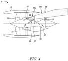
- the support structure 43 has a front mount 31 attaching the core casing 42 to a front attachment position of the pylon and a pair of thrust links 29 attaching the core casing 42 to a mid attachment position at a lower connection face of the pylon 13.
- the thrust links 29 are connected to the core casing 42 with the individual thrust links positioned on opposite lateral sides of the engine core 11.
- the thrust links 29 extend rearwardly, upwardly and inwardly from respective first ends at the core casing 42 to respective second ends at the mid attachment position of the pylon.
- the thrust links 29 may be joined to the lower connection face of pylon 13 via a balance beam or a whippletree arrangement. This can balance the thrust loads in the thrust links and substantially prevent yaw torques being reacted by the links.
- the support structure 43 also has a roll-torque transfer formation 33 attaching the core casing 42 to the mid attachment position of the pylon 13, and a rear mount 25 attaching the core casing 42 to a rear attachment position at the lower connection face of the pylon 13.
- This structure has to transmit axial, vertical and lateral loads, as well as roll, yaw and pitch torques from the engine to the pylon.
- the thrust links 29 transfer the axial loads from the engine 10 to the pylon 13, and each of the front 31 and rear 25 mounts transfers the lateral and vertical loads from the core casing 42 to the pylon 13. Furthermore, due to the substantial distance between the front and rear mounts, they also effectively transfer the yaw and pitch torques from the engine 10 to the pylon 13 via the front 31 and rear 25 mounts.
- the roll-torque transfer formation 33 then transfers the roll torques from the engine 10 to the pylon 13.
- the aircraft pylon 13 has a front section 13a having an open-lattice structure extending from the front attachment position to the mid attachment position and a boxed section 13b extending from the mid attachment position to the rear attachment position and then onwards to the connection of the pylon with the rest of the aircraft.
- the front section 13a is able to adopt the open-lattice structure, which facilitates engine-to-pylon systems routing, as it is not exposed to roll torques.
- the boxed section 13b which extends from the mid position rearwards, allows the pylon to transfer roll torques received via the roll-torque transfer formation 33 to the wider aircraft structure.
- the profiles of the front 31 and rear mounts 25 can be reduced without compromising their structural stability, as the majority of the axial loads and the roll torques are reacted respectively by the thrust links 29 and the roll-torque transfer formation 33, and thus the mechanical burden on the front 31 and rear 25 mounts is reduced.
- the front mount 31 can be brought forward to the base of FOGVs 44. These form a relatively stiff structure, and therefore connecting the front mount 31 at their base enhances stability and reduces core casing distortions. Additionally, the reaction of yaw and pitch torques by the front 31 and rear 25 mounts is improved due to the increased spacing between them.
- the pivotal joints can be spherical connections, allowing pivotal movement not only in the plane of the drawings (perpendicular to the engine axis), but also to some degree out of this plane. Such joints help the formation to absorb core casing movements which do not generate roll torque, including core casing thermal expansions.
- the length of the torque links 39a, 39b also allows them to absorb lateral and axial core casing movements due to thermal, mechanical or build/manufacturing tolerances by rotation of the pivotal joints.
- one or both torque links can be length adjustable for initial rigging onto the engine.
- a central portion of the beam forms a hinge joint 46.
- the torque beam 45 has a first half 45a having a male portion and a second half 45b having a female portion that receives the male portion of the first half 45a to form the hinge joint 46.
- This type of hinge joint 46 is relatively compact, which is advantageous when the available space under the lower connection face of the pylon 13 is limited.
- the torque beam 45 has a first half 45a and a second half 45b which are pivotally connected to respective ends of a central link 49 to form the hinge joint 46.
- this type of hinge joint 46 can reduce wear and/or fretting at the joint and reduce any backlash/ play in the system.
- Figures 6A and 6B respectively illustrate these different reactions of the roll-torque transfer formation 33 of Figure 5A to roll torques and vertical core casing movement.
- Figure 6A illustrates its reaction to a clockwise roll torque
- Figure 6B illustrates its reaction to a downward vertical movement.
- Directions of motion of the torque links 39a, 39b and the torque beam 45 are denoted by arrows.
- the first torque link 39a experiences an upwards vertical load and thereby moves upwardly
- the second torque link 39b experiences a downward vertical load and thereby moves downwardly
- Both torque links pivot at their upper and lower ends where they join to respectively the core casing 42 and the ends of the torque beam 45.
- Upward movement of the outer end of the first half 45a of the beam is reflected in downward movement of its male portion
- downward movement of the outer end of the second half 45b of the beam is reflected in upward movement of its female portion.
- the male and female portions of the hinge 46 thus engage with and react on each other such that the clockwise roll torque is transferred from the core casing 42 via the torque beam to the lower connection face of the pylon 13b at the support positions of the support bracket 37.
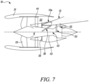
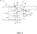
- FIGS 7 and 8 are schematic side views of the gas turbine engine 10 showing variants of the support structure 43 of Figure 4 .
- the front mount 31 is joined to a bulkhead 50 projecting from the core casing 42 behind the FOGVs 44, e.g. via a monoball connection.
- This is still a relatively stiff attachment position which does not generate substantial core casing distortions.
- the second ends of the thrust links 29 attach to a first mid attachment position and the roll-torque transfer formation 33 attaches to a second mid attachment position behind the first mid attachment position.
- the front mount 31 is joined to the engine 10 at the radially outer end of the topmost FOGVs 44.
- the forward pylon structure can be contained in a narrow upper bifurcation which extends over the full height of the fan bypass duct 22.
- FIG 9 is a schematic front view of a part of the gas turbine engine showing a variant of the support structure 43 of Figure 8 .
- the front mount 31 is joined to the engine via a twin link arrangement 52.
- Twin links 52 extend from opposite sides of a swing centre (not shown) coinciding with the centre of the front section 13a of the pylon 13 and thus substantially prevent roll torques being reacted into pylon 13.
- the twin links attach tangentially to the core casing 42 to further reduce core casing distortions.
- the front section 13a is a boxed section with cut-outs for systems routing rather than an open-lattice structure.
- the support structure 43 may be provided with failsafe features, such as dual elements or waiting failsafe catchers.
Landscapes
- Engineering & Computer Science (AREA)
- Aviation & Aerospace Engineering (AREA)
- Chemical & Material Sciences (AREA)
- Combustion & Propulsion (AREA)
- Mechanical Engineering (AREA)
- General Engineering & Computer Science (AREA)
- Structures Of Non-Positive Displacement Pumps (AREA)
Claims (14)
- Gasturbinenmotor (10) einschließlich einer Stützstruktur (43) zur Befestigung des Motors (10) an einem Flugzeugpylon (13) an vorderen, mittleren und hinteren Befestigungspositionen davon;
wobei der Motor ferner beinhaltet:einen Motorkern (11) umfassend eine Turbine (17, 19), einen Verdichter (14, 15) und eine Kernwelle (26, 27), welche die Turbine (17, 19) mit dem Verdichter (14, 15) verbindet; undein Kerngehäuse (42), das den Motorkern (11) umgibt; undwobei die Stützstruktur (43) beinhaltet:eine vordere Aufhängung (31), die mit dem Motor (10) verknüpft und zur Befestigung an dem Pylon (13) an der vorderen Befestigungsposition konfiguriert ist, und eine hintere Aufhängung (25), die mit dem Kerngehäuse (42) verknüpft und zur Befestigung an dem Pylon (13) an der hinteren Befestigungsposition (25) konfiguriert ist, wobei jede der vorderen (31) und hinteren (25) Aufhängung dazu konfiguriert ist, laterale und vertikale Lasten von dem Motor (10) auf den Pylon (13) zu übertragen, und die hintere Aufhängung (25) von der vorderen Aufhängung (31) beabstandet ist, sodass Gier- und Nickdrehmomente ebenfalls von dem Motor (10) durch die vordere (31) und hintere (25) Aufhängung auf den Pylon (13) übertragen werden;ein Axiallastübertragungsmittel (29), das dazu konfiguriert ist, Axiallasten von dem Motor (10) auf den Pylon (13) zu übertragen; undeine Rolldrehmoment-Übertragungsformation (33), die mit gegenüberliegenden lateralen Seiten des Kerngehäuses (42) verknüpft und zur Befestigung an dem Pylon (13) an der mittleren Befestigungsposition konfiguriert ist, um ein Rolldrehmoment von dem Kerngehäuse (42) auf den Pylon (13) zu übertragen, wobeidie Rolldrehmoment-Übertragungsformation (33) ein erstes Drehmomentglied (39a), das an einem unteren Ende davon schwenkbar mit einer Seite des Kerngehäuses (42) verknüpft ist, ein zweites Drehmomentglied (39b), das an einem unteren Ende davon schwenkbar mit der anderen Seite des Kerngehäuses (42) verknüpft ist, und einen Drehmomentbalken (45), der sich über die Oberseite des Kerngehäuses (45) erstreckt und der an gegenüberliegenden Enden des Balkens (45) schwenkbar mit jeweiligen oberen Enden des ersten (39a) und zweiten (39b) Drehmomentglieds verknüpft ist, aufweist;die Rolldrehmoment-Übertragungsformation (33) ferner eine Stützhalterung (37) aufweist, die zur Befestigung an dem Pylon (13) an der mittleren Befestigungsposition konfiguriert ist, wobei sich die Stützhalterung (37) schwenkbar an zwei lateral beabstandeten Stützpositionen zwischen den gegenüberliegenden Enden des Balkens (45) mit dem Drehmomentbalken (45) verbindet; undein zentraler Abschnitt des Drehmomentbalkens (45) zwischen den Stützpositionen eine Gelenkverbindung (46) bildet, sodass eine nach oben gerichtete vertikale Last, die durch eines der Drehmomentglieder (39a, 39b) übertragen wird, und eine gleichzeitige nach unten gerichtete vertikale Last, die durch das andere Drehmomentglied (39a, 39b) übertragen wird, an den Stützpositionen umgesetzt werden, um ein Rolldrehmoment von dem Kerngehäuse (42) auf den Pylon (13) zu übertragen, wohingegen eine gleichzeitige Bewegung beider Drehmomentglieder (39a, 39b) in der gleichen vertikalen Richtung die Gelenkverbindung (46) gelenkig lagert, um im Wesentlichen zu verhindern, dass vertikale Lasten an den Stützpositionen umgesetzt werden. - Gasturbinenmotor (10) nach Anspruch 1, wobei:
der Drehmomentbalken (45) eine erste Hälfte (45a), die für die Schwenkverknüpfung mit dem ersten Drehmomentglied (39a) und die Schwenkverbindung mit der Stützhalterung (37) an einer der Stützpositionen sorgt, und eine zweite Hälfte (45b), die für die Schwenkverknüpfung mit dem zweiten Drehmomentglied (39b) und die Schwenkverbindung mit der Stützhalterung (37) an der anderen Stützposition sorgt, aufweist; und die erste Hälfte (45a) des Drehmomentbalkens (45) einen Steckabschnitt aufweist, der in einem entsprechenden Buchsenabschnitt der zweiten Hälfte (45b) des Drehmomentbalkens (45) aufgenommen wird, um die Gelenkverbindung (46) zu bilden. - Gasturbinenmotor (10) nach Anspruch 1, wobei:der Drehmomentbalken (45) eine erste Hälfte (45a), die für die Schwenkverknüpfung mit dem ersten Drehmomentglied (39a) und die Schwenkverbindung mit der Stützhalterung (37) an einer der Stützpositionen sorgt, und eine zweite Hälfte (45b), die für die Schwenkverknüpfung mit dem zweiten Drehmomentglied (39b) und die Schwenkverbindung mit der Stützhalterung (37) an der anderen Stützposition sorgt, aufweist; unddie erste Hälfte (45a) des Drehmomentbalkens (45) und die zweite Hälfte (45b) des Drehmomentbalkens (45) schwenkbar mit jeweiligen Enden eines zentralen Glieds (49) verbunden sind, um die Gelenkverbindung (46) zu bilden.
- Gasturbinenmotor (10) nach einem der vorhergehenden Ansprüche, wobei der Motor (10) ferner ein Vortriebsgebläse (23), das sich stromaufwärts des Motorkerns (11) befindet, einen Umgehungskanal (22), der radial außerhalb des Motorkerns (11) angeordnet ist, um eine von dem Gebläse (23) erzeugte Umgehungsluftströmung einzugrenzen, und eine umfängliche Reihe von Auslassleitschaufeln (44), die sich über den Umgehungskanal (22) hinter dem Gebläse (23) erstrecken, beinhaltet.
- Gasturbinenmotor (10) nach Anspruch 4, wobei die vordere Aufhängung (31) an oder hinter den Auslassleitschaufeln (44) mit dem Kerngehäuse (42) verknüpft ist.
- Gasturbinenmotor (10) nach Anspruch 4, wobei die vordere Aufhängung (31) an einem radial äußeren Ende einer oder mehrerer der Auslassleitschaufeln (44) mit dem Motor verknüpft ist.
- Gasturbinenmotor (10) nach einem der vorhergehenden Ansprüche, wobei der Motor (10) ferner eine umfängliche Wärmeaustauscheinheit beinhaltet, die den Motorkern (11) umgibt, und die vordere Aufhängung (31) mit dem Kerngehäuse verknüpft ist, wobei sich die vordere Aufhängung unterhalb der Wärmeaustauscheinheit befindet.
- Gasturbinenmotor (10) nach einem der vorhergehenden Ansprüche, wobei die vordere Aufhängung (31) dazu konfiguriert ist, im Wesentlichen zu verhindern, dass ein Rolldrehmoment in den Pylon (13) dort umgesetzt wird.
- Gasturbinenmotor (10) nach einem der vorhergehenden Ansprüche, wobei das Axiallastübertragungsmittel die vordere Aufhängung (31) beinhaltet, die dazu konfiguriert ist, Axiallasten von dem Motor auf den Pylon zu übertragen.
- Gasturbinenmotor (10) nach einem der vorhergehenden Ansprüche, wobei das Axiallastübertragungsmittel (29) ein Paar Schubglieder ist, die auf gegenüberliegenden lateralen Seiten des Motorkerns (42) positioniert sind, wobei jedes Schubglied (29) ein erstes Ende aufweist, das sich mit einer jeweiligen lateralen Seite des Kerngehäuses (42) verknüpft, und wobei sich jedes Schubglied von seinem ersten Ende nach hinten, nach oben und nach innen zu einem zweiten Ende erstreckt, das zur Verkknüpfung mit dem Pylon (13) an einer weiteren mittleren Befestigungsposition davon konfiguriert ist, um Axiallasten von dem Motor (10) auf den Pylon (13) zu übertragen.
- Gasturbinenmotor (10) nach Anspruch 10, wobei die weitere mittlere Befestigungsposition des Pylons für die Schubglieder mit der mittleren Befestigungsposition des Pylons für die Rolldrehmoment-Übertragungsformation zusammenfällt oder sich vor dieser befindet.
- Gasturbinenmotor (10) nach einem der vorhergehenden Ansprüche, wobei: die Turbine (17, 19) eine erste Turbine (19) ist, der Verdichter (14, 15) ein erster Verdichter (14) ist und die Kernwelle (26, 27) eine erste Kernwelle (26) ist und der Motorkern (11) ferner eine zweite Turbine (17), einen zweiten Verdichter (15) und eine zweite Kernwelle (27), welche die zweite Turbine (17) mit dem zweiten Verdichter (15) verbindet, umfasst; und
die zweite Turbine (17), der zweite Verdichter (15) und die zweite Kernwelle (27) angeordnet sind, um sich mit einer höheren Drehzahl als die erste Kernwelle (26) zu drehen. - Flugzeug mit einem oder mehreren Gasturbinenmotoren (10) einschließlich jeweiliger Stützstrukturen (43) nach einem der vorhergehenden Ansprüche, wobei der eine oder die mehreren Gasturbinenmotoren (10) durch die Stützstrukturen (43) an jeweiligen Pylonen (13) des Flugzeugs befestigt sind.
- Flugzeug nach Anspruch 13, wobei der oder jeder Pylon (13) Folgendes aufweist:einen Kastenabschnitt (13b) zum Übertragen des Rolldrehmoments, der sich zwischen mindestens der mittleren Befestigungsposition der Rolldrehmoment-Übertragungsformation (33) und der hinteren Befestigungsposition erstreckt; undeinen vorderen Abschnitt (13a) mit einer offenen Gitterstruktur, die sich von der vorderen Befestigungsposition zu dem Kastenabschnitt erstreckt.
Applications Claiming Priority (1)
| Application Number | Priority Date | Filing Date | Title |
|---|---|---|---|
| GBGB2117778.7A GB202117778D0 (en) | 2021-12-09 | 2021-12-09 | Support structure for attaching a gas turbine engine to an aircraft pylon |
Publications (2)
| Publication Number | Publication Date |
|---|---|
| EP4194340A1 EP4194340A1 (de) | 2023-06-14 |
| EP4194340B1 true EP4194340B1 (de) | 2025-01-22 |
Family
ID=80079947
Family Applications (1)
| Application Number | Title | Priority Date | Filing Date |
|---|---|---|---|
| EP22206291.1A Active EP4194340B1 (de) | 2021-12-09 | 2022-11-09 | Stützstruktur zur befestigung eines gasturbinenmotors an einem flugzeugpylon |
Country Status (4)
| Country | Link |
|---|---|
| US (1) | US11945595B2 (de) |
| EP (1) | EP4194340B1 (de) |
| CN (1) | CN116280221A (de) |
| GB (1) | GB202117778D0 (de) |
Families Citing this family (2)
| Publication number | Priority date | Publication date | Assignee | Title |
|---|---|---|---|---|
| EP4488179A1 (de) * | 2023-07-04 | 2025-01-08 | Airbus Operations (S.A.S.) | Antriebsanordnung mit einem aufhängungssystem des hinteren teils des motorisierungsverfahrens, luftfahrzeug mit mindestens einer solchen antriebsanordnung |
| FR3167626A1 (fr) * | 2024-10-22 | 2026-04-24 | Safran Aircraft Engines | Ensemble pour aéronef comportant une turbomachine, un pylône et un système de fixation |
Family Cites Families (16)
| Publication number | Priority date | Publication date | Assignee | Title |
|---|---|---|---|---|
| IT1058337B (it) * | 1974-12-24 | 1982-04-10 | Rolls Royce 1971 Ltd | Perfezionamenti in o relativi al montaggio di motori a turbina a gas a by pass su aeromobili |
| US4603821A (en) * | 1983-12-30 | 1986-08-05 | The Boeing Company | System for mounting a jet engine |
| US4725019A (en) * | 1986-08-11 | 1988-02-16 | The Boeing Company | Aircraft engine mount with vertical vibration isolation |
| GB9927425D0 (en) * | 1999-11-20 | 2000-01-19 | Rolls Royce Plc | A gas turbine engine mounting arrangement |
| US7104306B2 (en) * | 2004-06-14 | 2006-09-12 | The Boeing Company | Cast unitized primary truss structure and method |
| GB0608983D0 (en) * | 2006-05-06 | 2006-06-14 | Rolls Royce Plc | Aeroengine mount |
| US9637241B2 (en) * | 2012-03-16 | 2017-05-02 | The Boeing Company | Engine mounting system for an aircraft |
| GB201310810D0 (en) * | 2013-06-18 | 2013-07-31 | Rolls Royce Deutschland & Co Kg | An accessory mounting for a gas turbine engine |
| FR3032180B1 (fr) * | 2015-01-30 | 2018-05-18 | Airbus Operations | Ensemble propulsif comportant un turboreacteur et un mat d'accrochage permettant une nouvelle distribution des efforts entre le turboreacteur et la voilure |
| FR3040369B1 (fr) * | 2015-09-02 | 2018-07-13 | Airbus Operations Sas | Ensemble moteur d'aeronef comprenant une attache moteur avant amelioree |
| FR3041935B1 (fr) * | 2015-10-05 | 2017-12-15 | Airbus Operations Sas | Ensemble moteur pour aeronef comprenant au moins deux attaches moteur arriere decalees axialement l'une de l'autre |
| FR3068008B1 (fr) | 2017-06-21 | 2019-11-08 | Airbus Operations | Ensemble de motorisation pour un aeronef |
| FR3078950B1 (fr) * | 2018-03-15 | 2020-12-18 | Airbus Operations Sas | Structure primaire d'un mat de support d'un groupe propulseur d'aeronef dont la partie arriere est formee par un ensemble de bielles |
| FR3079212B1 (fr) | 2018-03-26 | 2020-09-11 | Airbus Operations Sas | Ensemble de motorisation pour un aeronef |
| US20210300577A1 (en) * | 2020-03-31 | 2021-09-30 | General Electric Company | Engine backbone bending reduction |
| US11970278B2 (en) * | 2020-07-14 | 2024-04-30 | General Electric Company | Thrust mounts with load-balancing thrust link-lever |
-
2021
- 2021-12-09 GB GBGB2117778.7A patent/GB202117778D0/en not_active Ceased
-
2022
- 2022-11-09 EP EP22206291.1A patent/EP4194340B1/de active Active
- 2022-12-02 US US18/074,270 patent/US11945595B2/en active Active
- 2022-12-05 CN CN202211577684.2A patent/CN116280221A/zh active Pending
Also Published As
| Publication number | Publication date |
|---|---|
| US20230182912A1 (en) | 2023-06-15 |
| EP4194340A1 (de) | 2023-06-14 |
| GB202117778D0 (en) | 2022-01-26 |
| US11945595B2 (en) | 2024-04-02 |
| CN116280221A (zh) | 2023-06-23 |
Similar Documents
| Publication | Publication Date | Title |
|---|---|---|
| US20260002493A1 (en) | Engine mount system for a gas turbine engine | |
| EP1847457B1 (de) | Aufhängung eines Flugzeugtriebwerks | |
| EP3587773B1 (de) | Gasturbine | |
| US20170218789A1 (en) | Geared Architecture for High Speed and Small Volume Fan Drive Turbine | |
| CA2800001C (en) | Gas turbine engine compressor arrangement | |
| EP3922822B1 (de) | Motorlagerträger | |
| CN112923029B (zh) | 高功率周转齿轮箱及其操作 | |
| US20140301829A1 (en) | Engine Bearing Support | |
| US11174781B2 (en) | Aircraft propulsion assembly equipped with a main fan and with a least one offset fan | |
| US20120198817A1 (en) | Gas turbine engine with low stage count low pressure turbine | |
| EP4194340B1 (de) | Stützstruktur zur befestigung eines gasturbinenmotors an einem flugzeugpylon | |
| US20160047268A1 (en) | Gas turbine engine with low stage count low pressure turbine | |
| CN103958348A (zh) | 具有低级数低压涡轮的燃气涡轮发动机 | |
| EP4194339B1 (de) | Stützstruktur zur befestigung eines gasturbinenmotors an einem flugzeugpylon | |
| US11131209B2 (en) | Gas turbine | |
| EP3587764A1 (de) | Gasturbine | |
| EP3719262B1 (de) | Dichtungsanordnung für einen gasturbinenmotor | |
| EP4495409A1 (de) | Antriebsvorrichtung mit anordnung zur lokalisierung eines schubumkehrers |
Legal Events
| Date | Code | Title | Description |
|---|---|---|---|
| PUAI | Public reference made under article 153(3) epc to a published international application that has entered the european phase |
Free format text: ORIGINAL CODE: 0009012 |
|
| STAA | Information on the status of an ep patent application or granted ep patent |
Free format text: STATUS: THE APPLICATION HAS BEEN PUBLISHED |
|
| AK | Designated contracting states |
Kind code of ref document: A1 Designated state(s): AL AT BE BG CH CY CZ DE DK EE ES FI FR GB GR HR HU IE IS IT LI LT LU LV MC ME MK MT NL NO PL PT RO RS SE SI SK SM TR |
|
| STAA | Information on the status of an ep patent application or granted ep patent |
Free format text: STATUS: REQUEST FOR EXAMINATION WAS MADE |
|
| 17P | Request for examination filed |
Effective date: 20231127 |
|
| RBV | Designated contracting states (corrected) |
Designated state(s): AL AT BE BG CH CY CZ DE DK EE ES FI FR GB GR HR HU IE IS IT LI LT LU LV MC ME MK MT NL NO PL PT RO RS SE SI SK SM TR |
|
| REG | Reference to a national code |
Ref country code: DE Ref legal event code: R079 Free format text: PREVIOUS MAIN CLASS: B64D0027260000 Ipc: B64D0027400000 Ref document number: 602022009780 Country of ref document: DE |
|
| GRAP | Despatch of communication of intention to grant a patent |
Free format text: ORIGINAL CODE: EPIDOSNIGR1 |
|
| STAA | Information on the status of an ep patent application or granted ep patent |
Free format text: STATUS: GRANT OF PATENT IS INTENDED |
|
| GRAS | Grant fee paid |
Free format text: ORIGINAL CODE: EPIDOSNIGR3 |
|
| RIC1 | Information provided on ipc code assigned before grant |
Ipc: F02C 7/20 20060101ALI20241106BHEP Ipc: B64D 27/40 20240101AFI20241106BHEP |
|
| GRAA | (expected) grant |
Free format text: ORIGINAL CODE: 0009210 |
|
| STAA | Information on the status of an ep patent application or granted ep patent |
Free format text: STATUS: THE PATENT HAS BEEN GRANTED |
|
| INTG | Intention to grant announced |
Effective date: 20241121 |
|
| P01 | Opt-out of the competence of the unified patent court (upc) registered |
Free format text: CASE NUMBER: APP_63646/2024 Effective date: 20241129 |
|
| AK | Designated contracting states |
Kind code of ref document: B1 Designated state(s): AL AT BE BG CH CY CZ DE DK EE ES FI FR GB GR HR HU IE IS IT LI LT LU LV MC ME MK MT NL NO PL PT RO RS SE SI SK SM TR |
|
| REG | Reference to a national code |
Ref country code: GB Ref legal event code: FG4D |
|
| REG | Reference to a national code |
Ref country code: CH Ref legal event code: EP |
|
| REG | Reference to a national code |
Ref country code: IE Ref legal event code: FG4D |
|
| REG | Reference to a national code |
Ref country code: DE Ref legal event code: R096 Ref document number: 602022009780 Country of ref document: DE |
|
| REG | Reference to a national code |
Ref country code: NL Ref legal event code: MP Effective date: 20250122 |
|
| PG25 | Lapsed in a contracting state [announced via postgrant information from national office to epo] |
Ref country code: NL Free format text: LAPSE BECAUSE OF FAILURE TO SUBMIT A TRANSLATION OF THE DESCRIPTION OR TO PAY THE FEE WITHIN THE PRESCRIBED TIME-LIMIT Effective date: 20250122 |
|
| PG25 | Lapsed in a contracting state [announced via postgrant information from national office to epo] |
Ref country code: RS Free format text: LAPSE BECAUSE OF FAILURE TO SUBMIT A TRANSLATION OF THE DESCRIPTION OR TO PAY THE FEE WITHIN THE PRESCRIBED TIME-LIMIT Effective date: 20250422 |
|
| PG25 | Lapsed in a contracting state [announced via postgrant information from national office to epo] |
Ref country code: FI Free format text: LAPSE BECAUSE OF FAILURE TO SUBMIT A TRANSLATION OF THE DESCRIPTION OR TO PAY THE FEE WITHIN THE PRESCRIBED TIME-LIMIT Effective date: 20250122 |
|
| PG25 | Lapsed in a contracting state [announced via postgrant information from national office to epo] |
Ref country code: PL Free format text: LAPSE BECAUSE OF FAILURE TO SUBMIT A TRANSLATION OF THE DESCRIPTION OR TO PAY THE FEE WITHIN THE PRESCRIBED TIME-LIMIT Effective date: 20250122 |
|
| PG25 | Lapsed in a contracting state [announced via postgrant information from national office to epo] |
Ref country code: ES Free format text: LAPSE BECAUSE OF FAILURE TO SUBMIT A TRANSLATION OF THE DESCRIPTION OR TO PAY THE FEE WITHIN THE PRESCRIBED TIME-LIMIT Effective date: 20250122 |
|
| REG | Reference to a national code |
Ref country code: LT Ref legal event code: MG9D |
|
| PG25 | Lapsed in a contracting state [announced via postgrant information from national office to epo] |
Ref country code: NO Free format text: LAPSE BECAUSE OF FAILURE TO SUBMIT A TRANSLATION OF THE DESCRIPTION OR TO PAY THE FEE WITHIN THE PRESCRIBED TIME-LIMIT Effective date: 20250422 Ref country code: IS Free format text: LAPSE BECAUSE OF FAILURE TO SUBMIT A TRANSLATION OF THE DESCRIPTION OR TO PAY THE FEE WITHIN THE PRESCRIBED TIME-LIMIT Effective date: 20250522 |
|
| REG | Reference to a national code |
Ref country code: AT Ref legal event code: MK05 Ref document number: 1761309 Country of ref document: AT Kind code of ref document: T Effective date: 20250122 |
|
| PG25 | Lapsed in a contracting state [announced via postgrant information from national office to epo] |
Ref country code: HR Free format text: LAPSE BECAUSE OF FAILURE TO SUBMIT A TRANSLATION OF THE DESCRIPTION OR TO PAY THE FEE WITHIN THE PRESCRIBED TIME-LIMIT Effective date: 20250122 |
|
| PG25 | Lapsed in a contracting state [announced via postgrant information from national office to epo] |
Ref country code: PT Free format text: LAPSE BECAUSE OF FAILURE TO SUBMIT A TRANSLATION OF THE DESCRIPTION OR TO PAY THE FEE WITHIN THE PRESCRIBED TIME-LIMIT Effective date: 20250522 Ref country code: LV Free format text: LAPSE BECAUSE OF FAILURE TO SUBMIT A TRANSLATION OF THE DESCRIPTION OR TO PAY THE FEE WITHIN THE PRESCRIBED TIME-LIMIT Effective date: 20250122 |
|
| PG25 | Lapsed in a contracting state [announced via postgrant information from national office to epo] |
Ref country code: BG Free format text: LAPSE BECAUSE OF FAILURE TO SUBMIT A TRANSLATION OF THE DESCRIPTION OR TO PAY THE FEE WITHIN THE PRESCRIBED TIME-LIMIT Effective date: 20250122 Ref country code: GR Free format text: LAPSE BECAUSE OF FAILURE TO SUBMIT A TRANSLATION OF THE DESCRIPTION OR TO PAY THE FEE WITHIN THE PRESCRIBED TIME-LIMIT Effective date: 20250423 |
|
| PG25 | Lapsed in a contracting state [announced via postgrant information from national office to epo] |
Ref country code: AT Free format text: LAPSE BECAUSE OF FAILURE TO SUBMIT A TRANSLATION OF THE DESCRIPTION OR TO PAY THE FEE WITHIN THE PRESCRIBED TIME-LIMIT Effective date: 20250122 |
|
| PG25 | Lapsed in a contracting state [announced via postgrant information from national office to epo] |
Ref country code: SE Free format text: LAPSE BECAUSE OF FAILURE TO SUBMIT A TRANSLATION OF THE DESCRIPTION OR TO PAY THE FEE WITHIN THE PRESCRIBED TIME-LIMIT Effective date: 20250122 |
|
| PG25 | Lapsed in a contracting state [announced via postgrant information from national office to epo] |
Ref country code: SM Free format text: LAPSE BECAUSE OF FAILURE TO SUBMIT A TRANSLATION OF THE DESCRIPTION OR TO PAY THE FEE WITHIN THE PRESCRIBED TIME-LIMIT Effective date: 20250122 |
|
| PG25 | Lapsed in a contracting state [announced via postgrant information from national office to epo] |
Ref country code: DK Free format text: LAPSE BECAUSE OF FAILURE TO SUBMIT A TRANSLATION OF THE DESCRIPTION OR TO PAY THE FEE WITHIN THE PRESCRIBED TIME-LIMIT Effective date: 20250122 |
|
| PG25 | Lapsed in a contracting state [announced via postgrant information from national office to epo] |
Ref country code: IT Free format text: LAPSE BECAUSE OF FAILURE TO SUBMIT A TRANSLATION OF THE DESCRIPTION OR TO PAY THE FEE WITHIN THE PRESCRIBED TIME-LIMIT Effective date: 20250122 |
|
| PG25 | Lapsed in a contracting state [announced via postgrant information from national office to epo] |
Ref country code: EE Free format text: LAPSE BECAUSE OF FAILURE TO SUBMIT A TRANSLATION OF THE DESCRIPTION OR TO PAY THE FEE WITHIN THE PRESCRIBED TIME-LIMIT Effective date: 20250122 Ref country code: CZ Free format text: LAPSE BECAUSE OF FAILURE TO SUBMIT A TRANSLATION OF THE DESCRIPTION OR TO PAY THE FEE WITHIN THE PRESCRIBED TIME-LIMIT Effective date: 20250122 |
|
| REG | Reference to a national code |
Ref country code: DE Ref legal event code: R097 Ref document number: 602022009780 Country of ref document: DE |
|
| PG25 | Lapsed in a contracting state [announced via postgrant information from national office to epo] |
Ref country code: RO Free format text: LAPSE BECAUSE OF FAILURE TO SUBMIT A TRANSLATION OF THE DESCRIPTION OR TO PAY THE FEE WITHIN THE PRESCRIBED TIME-LIMIT Effective date: 20250122 |
|
| PG25 | Lapsed in a contracting state [announced via postgrant information from national office to epo] |
Ref country code: SK Free format text: LAPSE BECAUSE OF FAILURE TO SUBMIT A TRANSLATION OF THE DESCRIPTION OR TO PAY THE FEE WITHIN THE PRESCRIBED TIME-LIMIT Effective date: 20250122 |
|
| PLBE | No opposition filed within time limit |
Free format text: ORIGINAL CODE: 0009261 |
|
| STAA | Information on the status of an ep patent application or granted ep patent |
Free format text: STATUS: NO OPPOSITION FILED WITHIN TIME LIMIT |
|
| 26N | No opposition filed |
Effective date: 20251023 |
|
| PGFP | Annual fee paid to national office [announced via postgrant information from national office to epo] |
Ref country code: DE Payment date: 20251126 Year of fee payment: 4 |
|
| PGFP | Annual fee paid to national office [announced via postgrant information from national office to epo] |
Ref country code: FR Payment date: 20251124 Year of fee payment: 4 |