EP4194588B1 - Procédé d'étanchéification d'une cellule d'électrolyse et cellule d'électrolyse étanche - Google Patents
Procédé d'étanchéification d'une cellule d'électrolyse et cellule d'électrolyse étanche Download PDFInfo
- Publication number
- EP4194588B1 EP4194588B1 EP21213033.0A EP21213033A EP4194588B1 EP 4194588 B1 EP4194588 B1 EP 4194588B1 EP 21213033 A EP21213033 A EP 21213033A EP 4194588 B1 EP4194588 B1 EP 4194588B1
- Authority
- EP
- European Patent Office
- Prior art keywords
- cell
- sealing material
- sealing
- cell elements
- separator
- Prior art date
- Legal status (The legal status is an assumption and is not a legal conclusion. Google has not performed a legal analysis and makes no representation as to the accuracy of the status listed.)
- Active
Links
Images

Classifications
-
- C—CHEMISTRY; METALLURGY
- C25—ELECTROLYTIC OR ELECTROPHORETIC PROCESSES; APPARATUS THEREFOR
- C25B—ELECTROLYTIC OR ELECTROPHORETIC PROCESSES FOR THE PRODUCTION OF COMPOUNDS OR NON-METALS; APPARATUS THEREFOR
- C25B9/00—Cells or assemblies of cells; Constructional parts of cells; Assemblies of constructional parts, e.g. electrode-diaphragm assemblies; Process-related cell features
- C25B9/17—Cells comprising dimensionally-stable non-movable electrodes; Assemblies of constructional parts thereof
- C25B9/19—Cells comprising dimensionally-stable non-movable electrodes; Assemblies of constructional parts thereof with diaphragms
-
- C—CHEMISTRY; METALLURGY
- C09—DYES; PAINTS; POLISHES; NATURAL RESINS; ADHESIVES; COMPOSITIONS NOT OTHERWISE PROVIDED FOR; APPLICATIONS OF MATERIALS NOT OTHERWISE PROVIDED FOR
- C09J—ADHESIVES; NON-MECHANICAL ASPECTS OF ADHESIVE PROCESSES IN GENERAL; ADHESIVE PROCESSES NOT PROVIDED FOR ELSEWHERE; USE OF MATERIALS AS ADHESIVES
- C09J123/00—Adhesives based on homopolymers or copolymers of unsaturated aliphatic hydrocarbons having only one carbon-to-carbon double bond; Adhesives based on derivatives of such polymers
- C09J123/02—Adhesives based on homopolymers or copolymers of unsaturated aliphatic hydrocarbons having only one carbon-to-carbon double bond; Adhesives based on derivatives of such polymers not modified by chemical after-treatment
- C09J123/10—Homopolymers or copolymers of propene
- C09J123/12—Polypropene
-
- C—CHEMISTRY; METALLURGY
- C09—DYES; PAINTS; POLISHES; NATURAL RESINS; ADHESIVES; COMPOSITIONS NOT OTHERWISE PROVIDED FOR; APPLICATIONS OF MATERIALS NOT OTHERWISE PROVIDED FOR
- C09J—ADHESIVES; NON-MECHANICAL ASPECTS OF ADHESIVE PROCESSES IN GENERAL; ADHESIVE PROCESSES NOT PROVIDED FOR ELSEWHERE; USE OF MATERIALS AS ADHESIVES
- C09J127/00—Adhesives based on homopolymers or copolymers of compounds having one or more unsaturated aliphatic radicals, each having only one carbon-to-carbon double bond, and at least one being terminated by a halogen; Adhesives based on derivatives of such polymers
- C09J127/02—Adhesives based on homopolymers or copolymers of compounds having one or more unsaturated aliphatic radicals, each having only one carbon-to-carbon double bond, and at least one being terminated by a halogen; Adhesives based on derivatives of such polymers not modified by chemical after-treatment
- C09J127/04—Adhesives based on homopolymers or copolymers of compounds having one or more unsaturated aliphatic radicals, each having only one carbon-to-carbon double bond, and at least one being terminated by a halogen; Adhesives based on derivatives of such polymers not modified by chemical after-treatment containing chlorine atoms
- C09J127/06—Homopolymers or copolymers of vinyl chloride
-
- C—CHEMISTRY; METALLURGY
- C25—ELECTROLYTIC OR ELECTROPHORETIC PROCESSES; APPARATUS THEREFOR
- C25B—ELECTROLYTIC OR ELECTROPHORETIC PROCESSES FOR THE PRODUCTION OF COMPOUNDS OR NON-METALS; APPARATUS THEREFOR
- C25B1/00—Electrolytic production of inorganic compounds or non-metals
- C25B1/01—Products
- C25B1/02—Hydrogen or oxygen
- C25B1/04—Hydrogen or oxygen by electrolysis of water
-
- C—CHEMISTRY; METALLURGY
- C25—ELECTROLYTIC OR ELECTROPHORETIC PROCESSES; APPARATUS THEREFOR
- C25B—ELECTROLYTIC OR ELECTROPHORETIC PROCESSES FOR THE PRODUCTION OF COMPOUNDS OR NON-METALS; APPARATUS THEREFOR
- C25B1/00—Electrolytic production of inorganic compounds or non-metals
- C25B1/01—Products
- C25B1/24—Halogens or compounds thereof
- C25B1/26—Chlorine; Compounds thereof
-
- C—CHEMISTRY; METALLURGY
- C25—ELECTROLYTIC OR ELECTROPHORETIC PROCESSES; APPARATUS THEREFOR
- C25B—ELECTROLYTIC OR ELECTROPHORETIC PROCESSES FOR THE PRODUCTION OF COMPOUNDS OR NON-METALS; APPARATUS THEREFOR
- C25B9/00—Cells or assemblies of cells; Constructional parts of cells; Assemblies of constructional parts, e.g. electrode-diaphragm assemblies; Process-related cell features
- C25B9/01—Electrolytic cells characterised by shape or form
-
- C—CHEMISTRY; METALLURGY
- C25—ELECTROLYTIC OR ELECTROPHORETIC PROCESSES; APPARATUS THEREFOR
- C25B—ELECTROLYTIC OR ELECTROPHORETIC PROCESSES FOR THE PRODUCTION OF COMPOUNDS OR NON-METALS; APPARATUS THEREFOR
- C25B9/00—Cells or assemblies of cells; Constructional parts of cells; Assemblies of constructional parts, e.g. electrode-diaphragm assemblies; Process-related cell features
- C25B9/60—Constructional parts of cells
-
- C—CHEMISTRY; METALLURGY
- C25—ELECTROLYTIC OR ELECTROPHORETIC PROCESSES; APPARATUS THEREFOR
- C25B—ELECTROLYTIC OR ELECTROPHORETIC PROCESSES FOR THE PRODUCTION OF COMPOUNDS OR NON-METALS; APPARATUS THEREFOR
- C25B9/00—Cells or assemblies of cells; Constructional parts of cells; Assemblies of constructional parts, e.g. electrode-diaphragm assemblies; Process-related cell features
- C25B9/70—Assemblies comprising two or more cells
- C25B9/73—Assemblies comprising two or more cells of the filter-press type
- C25B9/77—Assemblies comprising two or more cells of the filter-press type having diaphragms
-
- C—CHEMISTRY; METALLURGY
- C25—ELECTROLYTIC OR ELECTROPHORETIC PROCESSES; APPARATUS THEREFOR
- C25B—ELECTROLYTIC OR ELECTROPHORETIC PROCESSES FOR THE PRODUCTION OF COMPOUNDS OR NON-METALS; APPARATUS THEREFOR
- C25B9/00—Cells or assemblies of cells; Constructional parts of cells; Assemblies of constructional parts, e.g. electrode-diaphragm assemblies; Process-related cell features
- C25B9/05—Pressure cells
-
- Y—GENERAL TAGGING OF NEW TECHNOLOGICAL DEVELOPMENTS; GENERAL TAGGING OF CROSS-SECTIONAL TECHNOLOGIES SPANNING OVER SEVERAL SECTIONS OF THE IPC; TECHNICAL SUBJECTS COVERED BY FORMER USPC CROSS-REFERENCE ART COLLECTIONS [XRACs] AND DIGESTS
- Y02—TECHNOLOGIES OR APPLICATIONS FOR MITIGATION OR ADAPTATION AGAINST CLIMATE CHANGE
- Y02E—REDUCTION OF GREENHOUSE GAS [GHG] EMISSIONS, RELATED TO ENERGY GENERATION, TRANSMISSION OR DISTRIBUTION
- Y02E60/00—Enabling technologies; Technologies with a potential or indirect contribution to GHG emissions mitigation
- Y02E60/30—Hydrogen technology
- Y02E60/36—Hydrogen production from non-carbon containing sources, e.g. by water electrolysis
Definitions
- the invention relates to a method for sealing an electrolysis cell according to the preamble of claim 1 and a sealed electrolysis cell according to the preamble of claim 7.
- Bipolar electrolyzers for large-scale production of hydrogen and/or chlorine can be classified in two major design categories, namely filter press design and single element design.
- a stack of electrolysis cells is formed in a cell rack by stacking a plurality of cell elements under interposition of sheet-like separators and gaskets between adjacent cell elements and compressing the complete stack in order to seal all electrolysis cells at once.
- each cell element forms the anode half-cell of one electrolysis cell and the cathode half-cell of a neighboring electrolysis cell in the stack.
- the sealing force for all cells is provided by tie-rods extending along the stack.
- each electrolysis cell is a separately sealed unit.
- Each electrolysis cell comprises two cell elements in the form of half-shells, which are bolted together in their rim regions, with a separator and gaskets interposed in-between.
- each cell element forms one half-cell of the electrolysis cell, the half-cells being separated by the separator.
- the sealing force for sealing the electrolysis cell is provided by the plurality bolts distributed circumferentially along the rim regions of the cell elements.
- the separator may be an ion exchange membrane, or a porous diaphragm, depending of the intended purpose of the electrolyzer. Further, in both design options a short-circuit between the two cell elements forming each electrolysis cell is to be reliably prevented, for which reason in addition to the gaskets usually at least one layer of electrically isolating material is interposed in the rim regions before sealing.
- US 2011/0259735 A1 shows examples of the filter press design and the single element design of bipolar electrolyzers.
- bipolar electrolyzers have the disadvantage that sealing of the cells causes a high assembly effort. Although in filter press electrolyzers the sealing force for all cells is provided by the same set of tie-rods, sealing of the cell stack is complicated and time-consuming since all separators, gaskets and isolation layers have to be correctly positioned at once.
- Single element electrolyzers require a high number of bolted connections for each element in order to prevent safely leakage during operation. Further, the space requirements for the structural elements needed to provide the sealing forces reduces the space available for cell volume, and in particular in the single element design the conventional sealing arrangement sets a lower limit for the thickness of each element.
- US 2005/0100776 A1 discloses a unitized membrane electrode assembly ("MEA") with an improved edge sealing for a solid polymer electrolyte cell.
- the membrane electrode assembly includes the polymer electrolyte membrane, anode and cathode, and gas diffusion backing layers for each electrode.
- Flow field plates made of conductive material that provide flow fields for the reactants are placed between adjacent MEAs. A number of MEAs and flow field plates are assembled to provide a fuel cell stack.
- EP 0 183 096 A1 describes a membrane unit comprising an ion exchange membrane and at least one layer of a second material adapted to reinforce the membrane, said reinforcing layer being secured to at least one side of the membrane around a gasket-bearing peripheral surface of the membrane.
- the reinforcing material can be bonded to the membrane e.g. by adhesive, heat sealing or ultrasonic sealing.
- a gasket is interposed between the membrane unit and an electrode frame on both side to form an electrolytic cell of the filter press type.
- JP 2006 004754 A relates to a fuel cell with a plate-shaped solid polyelectrolyte having an anode side metal plate and a cathode side metal plate in which gas flow passage grooves are formed.
- the peripheral edges of the metal plates are sealed by caulking in an electrically insulated state.
- US 2006/0073385 A1 relates to a method for sealing an electrolysis cell according to the preamble of claim 1 and a sealed electrolysis cell according to the preamble of claim 7.
- a heat-activated adhesive sealant material is used in a sealing process for uniting different components of an electrochemical cell.
- the adhesive sealant material encapsulates the edge portion of the membrane and interconnects the anode and cathode electrodes and plates of a single PEM cell.
- the object of the invention is to provide a method for sealing an electrolysis cell and a sealed electrolysis cell with a lower assembly effort and reduced space requirements of the sealing arrangement.
- a method for sealing an electrolysis cell comprising an anode half-cell and a cathode half-cell formed by at least two cell elements and a sheet-like separator separating the half-cells from one another is provided, the method comprising the following steps:
- the method according to the invention is particularly well suited for an automatized manufacturing of electrolysis cells.
- it enables electrolyzers of the filter press type to be assembled on a cell-by-cell basis, since the sealing forces according to the invention are provided by the adhesive bond between the sealing material and the cell elements.
- the sealing forces according to the invention are provided by the adhesive bond between the sealing material and the cell elements.
- the sealing material is a chemically curing adhesive or a solvent-based adhesive.
- Chemically curing and solvent-based adhesives have the advantage of a particularly strong adhesive bonding, which is able to withstand high temperatures and/or harsh chemicals.
- the layers of sealing material are preferably interposed by applying the adhesive in a viscous liquid state to the rim regions of both cell elements.
- the sealing material is a thermoplastic material, wherein the step of sealing the electrolysis cell comprises:
- Thermoplastic materials have the advantage that they allow for the possibility to open and reseal the electrolysis cell in an easy and non-destructive way.
- the rim regions can be heated up until the thermoplastic material is in the thermoplastic state again and the cell elements can be separated.
- the adhesive bond may be created in a two-step process, wherein the layers of sealing material are first bonded to the cell elements and wherein the two layers of sealing material are then bonded to each other and to the separator in the step of sealing.
- the first bond may for example already be present, when the two cell elements are provided, i.e. the cell elements are provided with a coating of thermoplastic material in their rim regions.
- the first bond may be created during the step of interposing the sealing material, or during the step of sealing.
- thermoplastic material can be brought into the thermoplastic state by different types of energy supply.
- the energy is input by heating of the rim regions.
- Another possible way to input the energy is thermowelding of the layers of sealing material by means of ultrasound.
- thermoplastic materials that contain polypropylene (PP), in particular atactic polypropylene (PP-R), and/or polyvinylchloride (PVC).
- PP polypropylene
- P-R atactic polypropylene
- PVC polyvinylchloride
- the step of sealing further comprises folding the rim regions of the cell elements backwards to one side.
- the backward fold of both rim regions to the same side e.g. by 120° to 180°, achieves a mechanical entanglement of the cell elements that further supports the sealing of the cell.
- the fold is advantageous in electrolysis cells to be operated at an elevated internal pressure, since the fold relieves the adhesive bond from the pressure force by a form lock.
- the cell elements are made of a metal sheet having a thickness of less than or equal to 0.8 mm.
- Preferred metals are nickel and/or titanium. Due to the sealing concept according to the invention, it is even imaginable to produce electrolysis cells from metal foils having a thickness of less than or equal to 0.2 mm.
- a sealed electrolysis cell comprising an anode half-cell and a cathode half-cell formed by at least two cell elements and a sheet-like separator separating the half-cells from one another.
- the cell elements each have a rim region and are attached to each other in the rim regions under interposition of a layer of sealing material between each side of the separator and the two cell elements in an electrically isolated and sealed manner.
- the sealing material is a solidified liquid material forming an adhesive bond between the cell elements and providing electric isolation and sealing of the cell elements.
- a major advantage of the sealed electrolysis cell of the invention is that the sealing forces are provided by an adhesive bond and external structural elements to maintain the sealing forces can be dispensed with.
- electrolyzers using this type of electrolysis cell better make use of the available space and the cells can be operated under less mechanical stress.
- the sealing arrangement is no longer limiting the possibility to design electrolysis cell of reduced thickness.
- the sealing material is a chemically cured adhesive or a dried solvent-based adhesive.
- the sealing material is a thermoplastic material.
- the sealing material contains polypropylene (PP) and/or polyvinylchloride (PVC).
- the edges of the sheet-like separator are immersed within the solidified sealing material.
- risks of leakage due to capillary effects of the separator can be avoided.
- porous diaphragms are used as separator, since porous diaphragms are known to cause leakages issues by capillary forces, if they extend between the rim regions of the cell elements to the outside of the cell.
- the rim regions of the cell elements are fold backwards to one side, so as to provide a mechanical form lock between the cell elements.
- the cell elements are made of a metal sheet having a thickness of less than or equal to 0.8 mm, in particular preferably less than or equal to 0.2mm.
- Preferred metals are nickel and/or titanium.
- the invention relates to electrolysis cells of industrial scale.
- the separator of the electrolysis cell according to the invention therefore preferably has an area of 0.5 m 2 to 4 m 2 .
- the electrolysis cell is preferably configured for current densities of at least 3 kA/m 2 .
- Fig. 1 a flow diagram of the method 100 for sealing an electrolysis cell is shown, illustrating the sequence of the steps in an abstract manner.
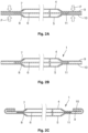
- Fig. 2A shows an electrolysis cell in a state before the sealing step of the method and
- Fig. 2B shows an embodiment of the sealed electrolysis cell 1.
- Fig. 2C shows a different embodiment of the sealed electrolysis cell 1 with backwards folded rim regions. The method steps will be described in the following with reference to Figs. 1 and 2A to 2C .
- step 110 two cell elements 4, 5 and a sheet-like separator 6 are provided.
- step 120 the separator 6 is interposed between the two cell elements 4, 5 and a layer of sealing material 7, 8 is interposed between each side of the separator 6 and the two cell elements 4, 5 in a respective rim region 9, 10 of the cell elements 4, 5.
- Fig. 2A shows the electrolysis cell in an assembly stage after step 120.
- step 130 the electrolysis cell 1 is sealed, wherein a force F is applied to the cell elements 4, 5 to compress the rim regions 9, 10.
- the sealing material 7, 8 is an electrically isolating material and during the sealing step 130 the state of the sealing material 7, 8 is changed from a liquid state to a solid state to create an adhesive bond of the cell elements 4, 5 and the interposed separator 6 by means of the sealing material 7, 8.
- the force F is relieved after the sealing material 7, 8 has solidified.
- Fig. 2B shows the sealed electrolysis cell 1 after step 130.
- the sealing material 7, 8 may be a chemically curing adhesive or a solvent-based adhesive.
- the sealing material 7, 8 is a thermoplastic material.
- the step of sealing 130 of the electrolysis cell 1 therefore further comprises a step of inputting energy 140 to the rim regions 9, 10 to bring the sealing material 7, 8 into a thermoplastic state, a step of bonding 150 the cell elements 4, 5 and the interposed separator 6 while the sealing material 7, 8 is in the thermoplastic state, and a step of lowering the temperature 160 of the sealing material 7, 8 to let the sealing material 7, 8 solidify.
- the sealing material 7, 8 contains polypropylene (PP) and/or polyvinylchloride (PVC).
- the energy may be input by heating of the rim regions 9, 10 to a temperature at which the sealing material is in its thermoplastic state.
- Lowering the temperature of the sealing material 7, 8 may e.g. be achieved by letting the temperature settle to the ambient temperature, or by an active cooling of the rim regions 9, 10.
- the step of sealing 130 further comprises folding 170 of the rim regions 9, 10 of the cell elements 4, 5 backwards to one side of the separator.
- the folding 170 may be carried out either after the sealing material has solidified, or before. In particular, if a chemically curing adhesive or a solvent-based adhesive is used, folding 170 is preferred to be carried out before the adhesive has solidified.
- Fig. 2C shows an embodiment of the sealed cell 1 after the step of folding 170.
- a sealed electrolysis cell 1 manufactured according to the inventive method is shown in Fig. 2B .
- the sealed electrolysis cell 1 comprises an anode half-cell 2 and a cathode half-cell 3 formed by at least two cell elements 4, 5 and a sheet-like separator 6 separating the half-cells 2, 3 from one another.
- the anode half-cell 2 and the cathode half-cell 3 contain an anode and a cathode, respectively (not shown).
- the anode and the cathode may be joined to the respective cell element 4, 5 in one piece, or may be configured as separate components.
- the cell elements 4, 5 each have a rim region 9, 10 and are attached to each other in the rim regions 9, 10 under interposition of a layer of sealing material 7, 8 between each side of the separator 6 and the two cell elements 4, 5 in an electrically isolated and sealed manner.
- the sealing material 7, 8 of the sealed cell 1 is a solidified liquid material forming an adhesive bond between the cell elements 4, 5 and providing electric isolation and sealing of the cell elements 4, 5.
- the solidified sealing material is a chemically cured adhesive or a dried solvent-based adhesive.
- the sealing material can be a thermoplastic material.
- the sealing material may contain polypropylene (PP) and/or polyvinylchloride (PVC).
- the edges 11 of the sheet-like separator 6 are preferably immersed within in the solidified sealing material.
- the sheet-like separator 6 does not extend through the rim regions 9, 10 to the outside of the cell, but is confined in a form-fitting manner within the adhesive bond between the cell elements 4, 5.
- the cell elements 4, 5 are made of a metal sheet having a thickness of less than or equal to 0.8 mm.
- the cell elements are made of a metal foil having a thickness of less than or equal to 0.1 mm.
- Preferred metals are nickel and titanium.
- the electrolysis cell 1 is preferably configured for alkaline water electrolysis or chlor-alkali electrolysis.
- Fig. 2C shows an embodiment of the sealed electrolysis cell 11, in which the rim regions 9, 10 of the cell elements 4, 5 are fold backwards to one side.
- the description of the embodiment shown in Fig. 2A is applicable to the embodiment shown in Fig. 2B , accordingly.
- the embodiments of Fig. 2B and 2C relate to electrolysis cells 1 of the single element design.
- the electrolysis cells 1 are configured as separate units, which can be connected electrically in series by abutting the backsides of the cell elements 4, 5 to an adjacent cell. Thereby, a stack of electrolysis cell 1 can be built and provided with power supply on the outer sides of the outmost cells of the stack.
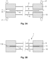
- Figs. 3A and 3B show an embodiment of the method and the sealed cell 1 of the filter press type.
- Each cell element 4, 5 provides an anode half-cell 2 and a cathode half-cell 3 of an adjacent cell.
- a plurality of cell elements 4, 5 can be sealed one-by-one to each other under interposition of one separator 6 each to for a stack of electrolysis cells 1 of the filter press type.
Landscapes
- Chemical & Material Sciences (AREA)
- Organic Chemistry (AREA)
- Engineering & Computer Science (AREA)
- Chemical Kinetics & Catalysis (AREA)
- Electrochemistry (AREA)
- Materials Engineering (AREA)
- Metallurgy (AREA)
- Inorganic Chemistry (AREA)
- Electrolytic Production Of Non-Metals, Compounds, Apparatuses Therefor (AREA)
- Sealing Battery Cases Or Jackets (AREA)
Claims (11)
- Procédé d'étanchéité d'une cellule d'électrolyse (1) comprenant une demi-cellule anodique (2) et une demi-cellule cathodique (3) formée par au moins deux éléments cellulaires (4, 5) et un séparateur en forme de feuille (6) séparant les demi-cellules (2, 3) l'une de l'autre, le procédé (100) comprenant les étapes suivantes :- fournir (110) les deux éléments cellulaires (4, 5) et le séparateur en forme de feuille (6),- interposer (120) le séparateur (6) entre les deux éléments cellulaires (4, 5) et interposer une couche de matériau d'étanchéité (7, 8) entre chaque côté du séparateur (6) et les deux éléments cellulaires (4, 5) dans une région de bord respectif (9, 10) des éléments cellulaires (4, 5),- étancher (130) la cellule d'électrolyse (1), une force (F) étant appliquée aux éléments cellulaires (4, 5) pour comprimer les zones de bord (9, 10),dans lequel le matériau d'étanchéité (7, 8) est un matériau d'isolation électrique, dans lequel, au cours de l'étape de étanchement (130), l'état du matériau d'étanchéité (7, 8) passe d'un état liquide à un état solide pour créer une liaison adhésive entre les éléments de la cellule (4, 5) et le séparateur interposé (6) au moyen du matériau d'étanchéité (7, 8), la force (F) étant supprimée lorsque le matériau d'étanchéité (7, 8) s'est solidifié, caractérisé en ce que les éléments cellulaires (4, 5) sont constitués d'une feuille de métal dont l'épaisseur est inférieure ou égale à 0,8 mm, en particulier inférieure ou égale à 0,2 mm.
- Procédé selon la revendication 1, caractérisé en ce que le matériau d'étanchéité (7, 8) est un adhésif à durcissement chimique ou un adhésif à base de solvant.
- Procédé selon la revendication 1, caractérisé en ce que le matériau d'étanchéité (7, 8) est un matériau thermoplastique, dans lequel l'étape de étanchement (130) de la cellule d'électrolyse (1) comprend :- l'apport d'énergie (140) au matériau d'étanchéité (7, 8) pour amener le matériau d'étanchéité (7, 8) dans un état thermoplastique,- coller (150) les éléments cellulaires (4, 5) et le séparateur intercalé (6) pendant que le matériau d'étanchéité (7, 8) est à l'état thermoplastique, et- abaisser la température (160) du matériau d'étanchéité (7, 8) pour permettre au matériau d'étanchéité (7, 8) de se solidifier.
- Méthode selon la revendication 3, caractérisée en ce que l'énergie est apportée par chauffage ou par ultrasons.
- Procédé selon la revendication 3 ou 4, caractérisé en ce que le matériau d'étanchéité (7, 8) contient du polypropylène (PP) et/ou du polychlorure de vinyle (PVC).
- Procédé selon l'une des revendications 1 à 5, caractérisé en ce que l'étape de étanchement (130) comprend en outre- plier (170) les zones de bord (9, 10) des éléments cellulaires (4, 5) vers l'arrière d'un côté.
- Cellule d'électrolyse étanche (1) comprenant une demi-cellule anodique (2) et une demi-cellule cathodique (3) formées par au moins deux éléments cellulaires (4, 5) et un séparateur en forme de feuille (6) séparant les demi-cellules (2, 3) l'une de l'autre, dans laquelle les éléments cellulaires (4, 5) ont chacun une région de bord (9, 10) et sont fixés l'un à l'autre dans les régions de bord (9, 10) sous l'interposition d'une couche de matériau d'étanchéité (7, 8) entre chaque côté du séparateur (6) et les deux éléments cellulaires (4, 5) d'une manière électriquement isolée et étanchée, dans laquelle le matériau d'étanchéité (7, 8) est un matériau liquide solidifié formant une liaison adhésive entre les éléments cellulaires (4, 5) et assurant l'isolation électrique et l'étanchement des éléments cellulaires (4, 5) caractérisé en ce que les éléments cellulaires (4, 5) sont constitués d'une feuille de métal d'une épaisseur inférieure ou égale à 0,8 mm, en particulier inférieure ou égale à 0,2 mm.
- Cellule d'électrolyse étanche selon la revendication 7, caractérisée en ce que le matériau d'étanchéité (7, 8) est un adhésif durci chimiquement ou un adhésif sec à base de solvant.
- Cellule d'électrolyse étanche selon la revendication 7, caractérisée en ce que le matériau d'étanchéité (7, 8) est un matériau thermoplastique.
- Cellule d'électrolyse étanche selon la revendication 9, caractérisée en ce que le matériau d'étanchéité (7, 8) contient du polypropylène (PP) et/ou du polychlorure de vinyle (PVC).
- Cellule d'électrolyse étanche selon l'une des revendications 7 à 10, caractérisée en ce que les zones de bord (9, 10) des éléments cellulaires (4, 5) sont repliées vers l'arrière sur un côté.
Priority Applications (10)
| Application Number | Priority Date | Filing Date | Title |
|---|---|---|---|
| ES21213033T ES2986402T3 (es) | 2021-12-08 | 2021-12-08 | Procedimiento de sellado de una celda de electrólisis y celda de electrólisis sellada |
| EP21213033.0A EP4194588B1 (fr) | 2021-12-08 | 2021-12-08 | Procédé d'étanchéification d'une cellule d'électrolyse et cellule d'électrolyse étanche |
| EP22830771.6A EP4444935A1 (fr) | 2021-12-08 | 2022-12-06 | Procédé pour l'étanchéification d'une cellule d'électrolyse et cellule d'électrolyse étanche |
| CN202280081012.4A CN118401704A (zh) | 2021-12-08 | 2022-12-06 | 用于密封电解槽的方法和密封式电解槽 |
| KR1020247020220A KR102991768B1 (ko) | 2021-12-08 | 2022-12-06 | 전해 셀의 밀봉 방법 및 밀봉된 전해 셀 |
| CA3240045A CA3240045A1 (fr) | 2021-12-08 | 2022-12-06 | Procede pour l'etancheification d'une cellule d'electrolyse et cellule d'electrolyse etanche |
| US18/717,708 US20250059656A1 (en) | 2021-12-08 | 2022-12-06 | Method for sealing an electrolysis cell and sealed electrolysis cell |
| JP2024534085A JP7835859B2 (ja) | 2021-12-08 | 2022-12-06 | 電解セルを封止するための方法および封止された電解セル |
| AU2022404755A AU2022404755B2 (en) | 2021-12-08 | 2022-12-06 | Method for sealing an electrolysis cell and sealed electrolysis cell |
| PCT/EP2022/084645 WO2023104817A1 (fr) | 2021-12-08 | 2022-12-06 | Procédé pour l'étanchéification d'une cellule d'électrolyse et cellule d'électrolyse étanche |
Applications Claiming Priority (1)
| Application Number | Priority Date | Filing Date | Title |
|---|---|---|---|
| EP21213033.0A EP4194588B1 (fr) | 2021-12-08 | 2021-12-08 | Procédé d'étanchéification d'une cellule d'électrolyse et cellule d'électrolyse étanche |
Publications (3)
| Publication Number | Publication Date |
|---|---|
| EP4194588A1 EP4194588A1 (fr) | 2023-06-14 |
| EP4194588B1 true EP4194588B1 (fr) | 2024-06-26 |
| EP4194588C0 EP4194588C0 (fr) | 2024-06-26 |
Family
ID=78824746
Family Applications (2)
| Application Number | Title | Priority Date | Filing Date |
|---|---|---|---|
| EP21213033.0A Active EP4194588B1 (fr) | 2021-12-08 | 2021-12-08 | Procédé d'étanchéification d'une cellule d'électrolyse et cellule d'électrolyse étanche |
| EP22830771.6A Pending EP4444935A1 (fr) | 2021-12-08 | 2022-12-06 | Procédé pour l'étanchéification d'une cellule d'électrolyse et cellule d'électrolyse étanche |
Family Applications After (1)
| Application Number | Title | Priority Date | Filing Date |
|---|---|---|---|
| EP22830771.6A Pending EP4444935A1 (fr) | 2021-12-08 | 2022-12-06 | Procédé pour l'étanchéification d'une cellule d'électrolyse et cellule d'électrolyse étanche |
Country Status (9)
| Country | Link |
|---|---|
| US (1) | US20250059656A1 (fr) |
| EP (2) | EP4194588B1 (fr) |
| JP (1) | JP7835859B2 (fr) |
| KR (1) | KR102991768B1 (fr) |
| CN (1) | CN118401704A (fr) |
| AU (1) | AU2022404755B2 (fr) |
| CA (1) | CA3240045A1 (fr) |
| ES (1) | ES2986402T3 (fr) |
| WO (1) | WO2023104817A1 (fr) |
Families Citing this family (3)
| Publication number | Priority date | Publication date | Assignee | Title |
|---|---|---|---|---|
| EP4194587B1 (fr) * | 2021-12-08 | 2024-06-26 | thyssenkrupp nucera AG & Co. KGaA | Électrolyseur dotée d'un boîtier de cellule constitué d'une feuille métallique |
| DK182204B1 (en) * | 2023-12-22 | 2025-11-25 | Nel Hydrogen Electrolyser As | An electrolysis cell element, an electrolysis cell stack, and use of an electrolysis cell stack |
| US20250283236A1 (en) * | 2024-03-06 | 2025-09-11 | Plug Power Inc. | Active tensioning for electrolyzer stacks |
Family Cites Families (10)
| Publication number | Priority date | Publication date | Assignee | Title |
|---|---|---|---|---|
| DK501585A (da) * | 1984-11-05 | 1986-05-06 | Dow Chemical Co | Membranenhed til en elektrolytcelle |
| DE19713250C2 (de) * | 1997-03-29 | 2002-04-18 | Ballard Power Systems | Elektrochemischer Energiewandler mit Polymerelektrolytmembran |
| KR101122473B1 (ko) | 2003-08-29 | 2012-02-29 | 이 아이 듀폰 디 네모아 앤드 캄파니 | 단위화된 막 전극 조립체 및 그의 제조 방법 |
| JP2005347256A (ja) | 2004-05-28 | 2005-12-15 | Ei Du Pont Canada Co | 電気化学的電池構成要素用の新規な密封剤 |
| JP2006004754A (ja) * | 2004-06-17 | 2006-01-05 | Nitto Denko Corp | 燃料電池 |
| JP2007157438A (ja) | 2005-12-02 | 2007-06-21 | Nitto Denko Corp | 燃料電池セルの製造方法及び燃料電池セルの製造設備 |
| IT1391774B1 (it) | 2008-11-17 | 2012-01-27 | Uhdenora Spa | Cella elementare e relativo elettrolizzatore modulare per processi elettrolitici |
| JP6031189B2 (ja) | 2013-04-30 | 2016-11-24 | 旭化成株式会社 | ガスケット及び電解槽 |
| DE102021103185A1 (de) * | 2021-02-11 | 2022-08-11 | WEW GmbH | Verfahren zur Abdichtung einer Elektrolysezelle |
| DE102021103699A1 (de) | 2021-02-17 | 2022-08-18 | WEW GmbH | Elektrolysezelle |
-
2021
- 2021-12-08 EP EP21213033.0A patent/EP4194588B1/fr active Active
- 2021-12-08 ES ES21213033T patent/ES2986402T3/es active Active
-
2022
- 2022-12-06 AU AU2022404755A patent/AU2022404755B2/en active Active
- 2022-12-06 KR KR1020247020220A patent/KR102991768B1/ko active Active
- 2022-12-06 EP EP22830771.6A patent/EP4444935A1/fr active Pending
- 2022-12-06 CA CA3240045A patent/CA3240045A1/fr active Pending
- 2022-12-06 US US18/717,708 patent/US20250059656A1/en active Pending
- 2022-12-06 WO PCT/EP2022/084645 patent/WO2023104817A1/fr not_active Ceased
- 2022-12-06 CN CN202280081012.4A patent/CN118401704A/zh active Pending
- 2022-12-06 JP JP2024534085A patent/JP7835859B2/ja active Active
Also Published As
| Publication number | Publication date |
|---|---|
| EP4444935A1 (fr) | 2024-10-16 |
| CN118401704A (zh) | 2024-07-26 |
| EP4194588A1 (fr) | 2023-06-14 |
| AU2022404755B2 (en) | 2026-02-05 |
| CA3240045A1 (fr) | 2023-06-15 |
| KR102991768B1 (ko) | 2026-07-15 |
| JP2024544224A (ja) | 2024-11-28 |
| JP7835859B2 (ja) | 2026-03-25 |
| KR20240110965A (ko) | 2024-07-16 |
| WO2023104817A1 (fr) | 2023-06-15 |
| EP4194588C0 (fr) | 2024-06-26 |
| ES2986402T3 (es) | 2024-11-11 |
| US20250059656A1 (en) | 2025-02-20 |
| AU2022404755A1 (en) | 2024-06-06 |
Similar Documents
| Publication | Publication Date | Title |
|---|---|---|
| US20250059656A1 (en) | Method for sealing an electrolysis cell and sealed electrolysis cell | |
| EP2946431B1 (fr) | Assemblage de pile à combustible, empilement de piles à combustible et procédés de préparation | |
| US10305135B2 (en) | Method of producing fuel cell stack and method of producing metal separator for fuel cell | |
| US8114555B2 (en) | Hardware system for high pressure electrochemical cell | |
| CN110224154B (zh) | 装备框架的膜电极组件及其生产方法,以及燃料电池 | |
| EP2523244B1 (fr) | Ensemble électrode-membrane-armature, procédé de fabrication de celui-ci et pile à combustible | |
| CA3233829A1 (fr) | Cadre pour cellules electrolytiques a pem et empilement de cellules electrolytiques a pem pour la production d'hydrogene haute pression par electrolyse a pression differentielle | |
| US9240609B2 (en) | Fuel cell and apparatus for producing fuel cell | |
| JP2017139218A (ja) | 燃料電池スタックの製造方法及び燃料電池用金属セパレータの製造方法 | |
| US20150228988A1 (en) | Membrane electrode assembly, fuel cell comprising assembly of this type and motor vehicle comprising said fuel cell | |
| EP2681796B1 (fr) | Pile à combustible du type à électrolyte polymère solide, et ensemble membrane électrolytique-électrode-cadre | |
| US20100143808A1 (en) | Fuel cell | |
| US8273495B2 (en) | Electrochemical cell structure and method of making the same | |
| EP2924787A1 (fr) | Cellule unique de pile à combustible | |
| US20230378506A1 (en) | Membrane-electrode unit for an electrochemical cell, and method for manufacturing a membrane-electrode unit | |
| US11024866B2 (en) | Elastomeric cell frame for fuel cell, method of manufacturing same, and unit cell having same | |
| CN119585895A (zh) | 将膜固定至框架的方法、单元堆和使用 | |
| US7294428B2 (en) | Method for reusing current collectors/distributors of solid polymer electrolyte fuel cell stacks | |
| JP5703186B2 (ja) | 燃料電池用樹脂枠付き電解質膜・電極構造体及びその製造方法 | |
| JP4880995B2 (ja) | 燃料電池モジュール及び燃料電池スタック | |
| US20250347015A1 (en) | Electrically isolated electrochemical cell and method of manufacturing the same | |
| US20250038239A1 (en) | Membrane-electrode assembly with sealed frame | |
| CN119605000A (zh) | 将膜固定至框架的方法、单元堆和使用 |
Legal Events
| Date | Code | Title | Description |
|---|---|---|---|
| PUAI | Public reference made under article 153(3) epc to a published international application that has entered the european phase |
Free format text: ORIGINAL CODE: 0009012 |
|
| STAA | Information on the status of an ep patent application or granted ep patent |
Free format text: STATUS: THE APPLICATION HAS BEEN PUBLISHED |
|
| AK | Designated contracting states |
Kind code of ref document: A1 Designated state(s): AL AT BE BG CH CY CZ DE DK EE ES FI FR GB GR HR HU IE IS IT LI LT LU LV MC MK MT NL NO PL PT RO RS SE SI SK SM TR |
|
| STAA | Information on the status of an ep patent application or granted ep patent |
Free format text: STATUS: REQUEST FOR EXAMINATION WAS MADE |
|
| 17P | Request for examination filed |
Effective date: 20231214 |
|
| RBV | Designated contracting states (corrected) |
Designated state(s): AL AT BE BG CH CY CZ DE DK EE ES FI FR GB GR HR HU IE IS IT LI LT LU LV MC MK MT NL NO PL PT RO RS SE SI SK SM TR |
|
| GRAP | Despatch of communication of intention to grant a patent |
Free format text: ORIGINAL CODE: EPIDOSNIGR1 |
|
| STAA | Information on the status of an ep patent application or granted ep patent |
Free format text: STATUS: GRANT OF PATENT IS INTENDED |
|
| INTG | Intention to grant announced |
Effective date: 20240219 |
|
| GRAS | Grant fee paid |
Free format text: ORIGINAL CODE: EPIDOSNIGR3 |
|
| GRAA | (expected) grant |
Free format text: ORIGINAL CODE: 0009210 |
|
| STAA | Information on the status of an ep patent application or granted ep patent |
Free format text: STATUS: THE PATENT HAS BEEN GRANTED |
|
| AK | Designated contracting states |
Kind code of ref document: B1 Designated state(s): AL AT BE BG CH CY CZ DE DK EE ES FI FR GB GR HR HU IE IS IT LI LT LU LV MC MK MT NL NO PL PT RO RS SE SI SK SM TR |
|
| REG | Reference to a national code |
Ref country code: GB Ref legal event code: FG4D |
|
| REG | Reference to a national code |
Ref country code: CH Ref legal event code: EP |
|
| REG | Reference to a national code |
Ref country code: DE Ref legal event code: R096 Ref document number: 602021014794 Country of ref document: DE |
|
| U01 | Request for unitary effect filed |
Effective date: 20240626 |
|
| U07 | Unitary effect registered |
Designated state(s): AT BE BG DE DK EE FI FR IT LT LU LV MT NL PT SE SI Effective date: 20240702 |
|
| PG25 | Lapsed in a contracting state [announced via postgrant information from national office to epo] |
Ref country code: HR Free format text: LAPSE BECAUSE OF FAILURE TO SUBMIT A TRANSLATION OF THE DESCRIPTION OR TO PAY THE FEE WITHIN THE PRESCRIBED TIME-LIMIT Effective date: 20240626 |
|
| PG25 | Lapsed in a contracting state [announced via postgrant information from national office to epo] |
Ref country code: GR Free format text: LAPSE BECAUSE OF FAILURE TO SUBMIT A TRANSLATION OF THE DESCRIPTION OR TO PAY THE FEE WITHIN THE PRESCRIBED TIME-LIMIT Effective date: 20240927 |
|
| PG25 | Lapsed in a contracting state [announced via postgrant information from national office to epo] |
Ref country code: NO Free format text: LAPSE BECAUSE OF FAILURE TO SUBMIT A TRANSLATION OF THE DESCRIPTION OR TO PAY THE FEE WITHIN THE PRESCRIBED TIME-LIMIT Effective date: 20240926 Ref country code: HR Free format text: LAPSE BECAUSE OF FAILURE TO SUBMIT A TRANSLATION OF THE DESCRIPTION OR TO PAY THE FEE WITHIN THE PRESCRIBED TIME-LIMIT Effective date: 20240626 Ref country code: GR Free format text: LAPSE BECAUSE OF FAILURE TO SUBMIT A TRANSLATION OF THE DESCRIPTION OR TO PAY THE FEE WITHIN THE PRESCRIBED TIME-LIMIT Effective date: 20240927 Ref country code: RS Free format text: LAPSE BECAUSE OF FAILURE TO SUBMIT A TRANSLATION OF THE DESCRIPTION OR TO PAY THE FEE WITHIN THE PRESCRIBED TIME-LIMIT Effective date: 20240926 |
|
| REG | Reference to a national code |
Ref country code: ES Ref legal event code: FG2A Ref document number: 2986402 Country of ref document: ES Kind code of ref document: T3 Effective date: 20241111 |
|
| PG25 | Lapsed in a contracting state [announced via postgrant information from national office to epo] |
Ref country code: PL Free format text: LAPSE BECAUSE OF FAILURE TO SUBMIT A TRANSLATION OF THE DESCRIPTION OR TO PAY THE FEE WITHIN THE PRESCRIBED TIME-LIMIT Effective date: 20240626 |
|
| PG25 | Lapsed in a contracting state [announced via postgrant information from national office to epo] |
Ref country code: IS Free format text: LAPSE BECAUSE OF FAILURE TO SUBMIT A TRANSLATION OF THE DESCRIPTION OR TO PAY THE FEE WITHIN THE PRESCRIBED TIME-LIMIT Effective date: 20241026 |
|
| PG25 | Lapsed in a contracting state [announced via postgrant information from national office to epo] |
Ref country code: CZ Free format text: LAPSE BECAUSE OF FAILURE TO SUBMIT A TRANSLATION OF THE DESCRIPTION OR TO PAY THE FEE WITHIN THE PRESCRIBED TIME-LIMIT Effective date: 20240626 |
|
| PG25 | Lapsed in a contracting state [announced via postgrant information from national office to epo] |
Ref country code: RO Free format text: LAPSE BECAUSE OF FAILURE TO SUBMIT A TRANSLATION OF THE DESCRIPTION OR TO PAY THE FEE WITHIN THE PRESCRIBED TIME-LIMIT Effective date: 20240626 Ref country code: SK Free format text: LAPSE BECAUSE OF FAILURE TO SUBMIT A TRANSLATION OF THE DESCRIPTION OR TO PAY THE FEE WITHIN THE PRESCRIBED TIME-LIMIT Effective date: 20240626 |
|
| PG25 | Lapsed in a contracting state [announced via postgrant information from national office to epo] |
Ref country code: SM Free format text: LAPSE BECAUSE OF FAILURE TO SUBMIT A TRANSLATION OF THE DESCRIPTION OR TO PAY THE FEE WITHIN THE PRESCRIBED TIME-LIMIT Effective date: 20240626 |
|
| PG25 | Lapsed in a contracting state [announced via postgrant information from national office to epo] |
Ref country code: SM Free format text: LAPSE BECAUSE OF FAILURE TO SUBMIT A TRANSLATION OF THE DESCRIPTION OR TO PAY THE FEE WITHIN THE PRESCRIBED TIME-LIMIT Effective date: 20240626 Ref country code: SK Free format text: LAPSE BECAUSE OF FAILURE TO SUBMIT A TRANSLATION OF THE DESCRIPTION OR TO PAY THE FEE WITHIN THE PRESCRIBED TIME-LIMIT Effective date: 20240626 Ref country code: RO Free format text: LAPSE BECAUSE OF FAILURE TO SUBMIT A TRANSLATION OF THE DESCRIPTION OR TO PAY THE FEE WITHIN THE PRESCRIBED TIME-LIMIT Effective date: 20240626 Ref country code: PL Free format text: LAPSE BECAUSE OF FAILURE TO SUBMIT A TRANSLATION OF THE DESCRIPTION OR TO PAY THE FEE WITHIN THE PRESCRIBED TIME-LIMIT Effective date: 20240626 Ref country code: IS Free format text: LAPSE BECAUSE OF FAILURE TO SUBMIT A TRANSLATION OF THE DESCRIPTION OR TO PAY THE FEE WITHIN THE PRESCRIBED TIME-LIMIT Effective date: 20241026 Ref country code: CZ Free format text: LAPSE BECAUSE OF FAILURE TO SUBMIT A TRANSLATION OF THE DESCRIPTION OR TO PAY THE FEE WITHIN THE PRESCRIBED TIME-LIMIT Effective date: 20240626 |
|
| U20 | Renewal fee for the european patent with unitary effect paid |
Year of fee payment: 4 Effective date: 20241227 |
|
| PLBE | No opposition filed within time limit |
Free format text: ORIGINAL CODE: 0009261 |
|
| STAA | Information on the status of an ep patent application or granted ep patent |
Free format text: STATUS: NO OPPOSITION FILED WITHIN TIME LIMIT |
|
| 26N | No opposition filed |
Effective date: 20250327 |
|
| PG25 | Lapsed in a contracting state [announced via postgrant information from national office to epo] |
Ref country code: MC Free format text: LAPSE BECAUSE OF FAILURE TO SUBMIT A TRANSLATION OF THE DESCRIPTION OR TO PAY THE FEE WITHIN THE PRESCRIBED TIME-LIMIT Effective date: 20240626 |
|
| REG | Reference to a national code |
Ref country code: CH Ref legal event code: PL |
|
| PG25 | Lapsed in a contracting state [announced via postgrant information from national office to epo] |
Ref country code: CH Free format text: LAPSE BECAUSE OF NON-PAYMENT OF DUE FEES Effective date: 20241231 |
|
| PG25 | Lapsed in a contracting state [announced via postgrant information from national office to epo] |
Ref country code: IE Free format text: LAPSE BECAUSE OF NON-PAYMENT OF DUE FEES Effective date: 20241208 |
|
| PGFP | Annual fee paid to national office [announced via postgrant information from national office to epo] |
Ref country code: GB Payment date: 20251219 Year of fee payment: 5 |
|
| U20 | Renewal fee for the european patent with unitary effect paid |
Year of fee payment: 5 Effective date: 20251230 |
|
| PGFP | Annual fee paid to national office [announced via postgrant information from national office to epo] |
Ref country code: ES Payment date: 20260130 Year of fee payment: 5 |
|
| PG25 | Lapsed in a contracting state [announced via postgrant information from national office to epo] |
Ref country code: CY Free format text: LAPSE BECAUSE OF FAILURE TO SUBMIT A TRANSLATION OF THE DESCRIPTION OR TO PAY THE FEE WITHIN THE PRESCRIBED TIME-LIMIT Effective date: 20240626 |
|
| PG25 | Lapsed in a contracting state [announced via postgrant information from national office to epo] |
Ref country code: TR Free format text: LAPSE BECAUSE OF FAILURE TO SUBMIT A TRANSLATION OF THE DESCRIPTION OR TO PAY THE FEE WITHIN THE PRESCRIBED TIME-LIMIT Effective date: 20240626 |
|
| PG25 | Lapsed in a contracting state [announced via postgrant information from national office to epo] |
Ref country code: HU Free format text: LAPSE BECAUSE OF FAILURE TO SUBMIT A TRANSLATION OF THE DESCRIPTION OR TO PAY THE FEE WITHIN THE PRESCRIBED TIME-LIMIT; INVALID AB INITIO Effective date: 20211208 |