EP4196382B1 - Chariot de transport et procédé de transformation d'un chariot de transport - Google Patents
Chariot de transport et procédé de transformation d'un chariot de transport Download PDFInfo
- Publication number
- EP4196382B1 EP4196382B1 EP21709445.7A EP21709445A EP4196382B1 EP 4196382 B1 EP4196382 B1 EP 4196382B1 EP 21709445 A EP21709445 A EP 21709445A EP 4196382 B1 EP4196382 B1 EP 4196382B1
- Authority
- EP
- European Patent Office
- Prior art keywords
- operating mode
- wheel
- transport
- movement
- cable
- Prior art date
- Legal status (The legal status is an assumption and is not a legal conclusion. Google has not performed a legal analysis and makes no representation as to the accuracy of the status listed.)
- Active
Links
Images
































Classifications
-
- B—PERFORMING OPERATIONS; TRANSPORTING
- B62—LAND VEHICLES FOR TRAVELLING OTHERWISE THAN ON RAILS
- B62B—HAND-PROPELLED VEHICLES, e.g. HAND CARTS OR PERAMBULATORS; SLEDGES
- B62B3/00—Hand carts having more than one axis carrying transport wheels; Steering devices therefor; Equipment therefor
- B62B3/02—Hand carts having more than one axis carrying transport wheels; Steering devices therefor; Equipment therefor involving parts being adjustable, collapsible, attachable, detachable or convertible
-
- B—PERFORMING OPERATIONS; TRANSPORTING
- B62—LAND VEHICLES FOR TRAVELLING OTHERWISE THAN ON RAILS
- B62B—HAND-PROPELLED VEHICLES, e.g. HAND CARTS OR PERAMBULATORS; SLEDGES
- B62B3/00—Hand carts having more than one axis carrying transport wheels; Steering devices therefor; Equipment therefor
- B62B3/02—Hand carts having more than one axis carrying transport wheels; Steering devices therefor; Equipment therefor involving parts being adjustable, collapsible, attachable, detachable or convertible
- B62B3/022—Hand carts having more than one axis carrying transport wheels; Steering devices therefor; Equipment therefor involving parts being adjustable, collapsible, attachable, detachable or convertible folding down the body to the wheel carriage or by retracting projecting parts
-
- B—PERFORMING OPERATIONS; TRANSPORTING
- B62—LAND VEHICLES FOR TRAVELLING OTHERWISE THAN ON RAILS
- B62B—HAND-PROPELLED VEHICLES, e.g. HAND CARTS OR PERAMBULATORS; SLEDGES
- B62B5/00—Accessories or details specially adapted for hand carts
- B62B5/06—Hand moving equipment, e.g. handle bars
-
- B—PERFORMING OPERATIONS; TRANSPORTING
- B62—LAND VEHICLES FOR TRAVELLING OTHERWISE THAN ON RAILS
- B62B—HAND-PROPELLED VEHICLES, e.g. HAND CARTS OR PERAMBULATORS; SLEDGES
- B62B5/00—Accessories or details specially adapted for hand carts
- B62B5/06—Hand moving equipment, e.g. handle bars
- B62B5/064—Hand moving equipment, e.g. handle bars adaptable for different users, e.g. by means of pivoting elements
- B62B5/065—Hand moving equipment, e.g. handle bars adaptable for different users, e.g. by means of pivoting elements by means of telescopic elements
-
- B—PERFORMING OPERATIONS; TRANSPORTING
- B62—LAND VEHICLES FOR TRAVELLING OTHERWISE THAN ON RAILS
- B62B—HAND-PROPELLED VEHICLES, e.g. HAND CARTS OR PERAMBULATORS; SLEDGES
- B62B5/00—Accessories or details specially adapted for hand carts
- B62B5/06—Hand moving equipment, e.g. handle bars
- B62B5/067—Stowable or retractable handle bars
-
- B—PERFORMING OPERATIONS; TRANSPORTING
- B62—LAND VEHICLES FOR TRAVELLING OTHERWISE THAN ON RAILS
- B62B—HAND-PROPELLED VEHICLES, e.g. HAND CARTS OR PERAMBULATORS; SLEDGES
- B62B2202/00—Indexing codes relating to type or characteristics of transported articles
- B62B2202/12—Boxes, Crates
-
- B—PERFORMING OPERATIONS; TRANSPORTING
- B62—LAND VEHICLES FOR TRAVELLING OTHERWISE THAN ON RAILS
- B62B—HAND-PROPELLED VEHICLES, e.g. HAND CARTS OR PERAMBULATORS; SLEDGES
- B62B2205/00—Hand-propelled vehicles or sledges being foldable or dismountable when not in use
- B62B2205/003—Hand-propelled vehicles or sledges being foldable or dismountable when not in use with actuation mechanisms which drive the folding or unfolding operation
-
- B—PERFORMING OPERATIONS; TRANSPORTING
- B62—LAND VEHICLES FOR TRAVELLING OTHERWISE THAN ON RAILS
- B62B—HAND-PROPELLED VEHICLES, e.g. HAND CARTS OR PERAMBULATORS; SLEDGES
- B62B2205/00—Hand-propelled vehicles or sledges being foldable or dismountable when not in use
- B62B2205/04—Hand-propelled vehicles or sledges being foldable or dismountable when not in use box-shaped in folded position
-
- B—PERFORMING OPERATIONS; TRANSPORTING
- B62—LAND VEHICLES FOR TRAVELLING OTHERWISE THAN ON RAILS
- B62B—HAND-PROPELLED VEHICLES, e.g. HAND CARTS OR PERAMBULATORS; SLEDGES
- B62B2205/00—Hand-propelled vehicles or sledges being foldable or dismountable when not in use
- B62B2205/06—Foldable with a scissor-like mechanism
-
- B—PERFORMING OPERATIONS; TRANSPORTING
- B62—LAND VEHICLES FOR TRAVELLING OTHERWISE THAN ON RAILS
- B62B—HAND-PROPELLED VEHICLES, e.g. HAND CARTS OR PERAMBULATORS; SLEDGES
- B62B2206/00—Adjustable or convertible hand-propelled vehicles or sledges
- B62B2206/06—Adjustable or convertible hand-propelled vehicles or sledges adjustable in height
Definitions
- the present invention relates to transport trolleys comprising a base assembly, two opposing side assemblies arranged on the base assembly, one wheel arranged on each of the side assemblies, and at least one receptacle arranged between the side assemblies for a transport box. Furthermore, the present invention relates to a method for transferring such a transport trolley between a packing mode and a first operating mode. Furthermore, the present invention relates to a method for transferring such a transport trolley between a first operating mode and a second operating mode.
- the printed matter DE 197 07 744 C1 a collapsible transport trolley with a substantially cubic container, the opposing first and mutually opposite second side walls extend, in the unfolded state, between the base and a frame having handle elements and closing off the container at the top, wherein the first side walls are mounted on the frame and are articulated to the base, and the second side walls are supportable on the base and each accommodate at least one wheel which is movable between a driving position projecting beyond the wall surface and a rest position lying within the wall surface, wherein the first side walls, which are each mounted on the frame and on the base, are designed to be foldable in such a way that the frame and the base can essentially be placed on top of one another when the second side walls are pivoted in horizontally, and wherein a rod for handling is arranged on the frame and is movable between a handling position projecting beyond the container and a storage position nestling against the container or lying within the container.
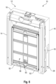
- the trolley In packing mode, the trolley is folded up compactly, in particular to save space, and therefore takes up little space.
- This packing mode is therefore particularly suitable for transporting or storing the trolley, for example in the trunk of a car.
- the two side assemblies are folded up in packing mode.
- the two side assemblies which are arranged on opposite sides of the base assembly, are folded towards each other in packing mode so that the side assemblies are aligned with each other and rest against the base assembly.
- the side assemblies extend towards each other along the base assembly.
- each wheel is preferably folded into the corresponding side assembly.
- each side assembly can have a corresponding opening through which the corresponding wheel can be folded in or unfolded.
- each wheel In the folded position, each wheel is preferably arranged completely in the corresponding side assembly. In the unfolded position, each wheel is preferably completely or at least partially unfolded from the corresponding side assembly.
- the side assemblies are in particular unfolded.
- the two side assemblies are arranged parallel to each other in the first and second operating modes.
- the side assemblies extend away from the base assembly, preferably perpendicular to the base assembly.
- each wheel is preferably The side assembly is folded out so that the trolley can be pulled or pushed along the floor using the wheels.
- the wheels are thus in the first and In the second operating mode, the wheels can be arranged on the ground or are oriented towards the ground.
- the wheels are thus arranged on an underside of the trolley in the first and second operating modes.
- the side of the trolley opposite the underside is thus referred to as the top side of the trolley.
- the transport trolley can be easily pulled.
- the first operating mode is therefore particularly suitable for pulling the transport trolley.
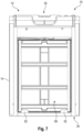
- the holder for the transport box is arranged in a transport position.
- the transport position can also be referred to as the low position, in which the holder is arranged close to the unfolded wheels.
- a transport box arranged in the holder is therefore arranged low, so that the total weight of the transport box and its contents are closer to a rotation axis of the wheels. This makes the transport box easier to transport.
- the transport trolley can be easily pushed or loaded.
- the second operating mode is therefore particularly suitable for pushing or loading the transport trolley.
- the holder for the transport box is arranged in a loading position.
- the loading position can also be referred to as the high position, in which the holder is arranged further away from the wheels than in the low position.
- a transport box arranged in the holder is therefore also arranged higher.
- the loading position is therefore particularly suitable for loading the transport box, as a user does not have to bend down as much or at all to load the transport box.
- the two side assemblies are unfolded.
- the side assemblies are transferred from a closed position to an unfolded position. Since the movement of the side assembly between the folded and unfolded positions is coupled with the movement of the wheels between the folded and unfolded positions, the wheels are automatically unfolded when the side assembly is unfolded. In other words, the wheels are also moved from the folded position to the unfolded position.
- the actuating element is moved in the first direction of movement.
- the actuating element is preferably designed mechanically, for example as a rotatable coupling body, as a lever, as a turntable, or similar.
- an electrical, hydraulic, or pneumatic drive device can also be provided as the actuating element.
- the actuating element is also moved in the first direction of movement.
- the actuating element can, for example, perform a pumping movement, in particular an alternating movement in the first direction of movement and against the first direction of movement, whereby only the movement in the first direction of movement contributes to the transfer of the transport carriage. This is particularly advantageous for manual actuation.
- the drive device only needs to be suitable for performing a movement in one direction of movement, in particular the first direction of movement, which considerably simplifies the requirements for a drive device.
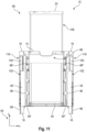
- the transport trolley further comprises a support on each side assembly.
- each support is arranged in a folded position in the packing mode and in an unfolded position in the first operating mode, in particular wherein each support is pivotally mounted on the corresponding side assembly about an axis between the folded position and the unfolded position.
- the supports can be folded in to save space in the packing mode and unfolded in the first operating mode for operating the transport trolley.
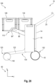
- Each support wheel 100 is arranged via a second arm 122 on the corresponding side assembly 16.
- Each second arm 122 is pivotally mounted about an axis in the corresponding side assembly 16. In the first operating mode 86, these pivot axes run parallel to the x-direction.
- the pivot axes of the second arms 122 are arranged in particular in alignment with one another.
- Each support wheel 100 is arranged at one end of the respective second arm 122, wherein the bearing point the pivot axis is arranged at the other, opposite end of the respective second arm 122.
- the third lever 174 is rotationally fixedly coupled to a deflection pulley around which the further cable 168 runs.
- This deflection pulley is also freely rotatably mounted on the pivot axis 166.
- a pulling movement of the cable 168 is transmitted to a rotating movement of the deflection pulley and thus also to a pivoting movement of the third lever 174.
- a first end of the cable 168 is coupled to the second lever 156.
- the first end of the cable 168 is attached or fastened to a fastening point 178 on the second lever 156.
- the second end of the cable 168 is coupled to a spring element 180, wherein the spring element 180 is tensioned when the cable 168 is pulled towards the first end.
- the cable 168 is deflected around a deflection pulley 170.
- the deflection pulley 170 is arranged with respect to the course of the cable 168 between the deflection pulley mounted on the pivot axis 166 and the second lever 156.
- the toggle lever 146 is coupled directly via the lever 154 to the arm 124 of the wheel 18 and via the cable 168 and the lever 174 to the arm 172 of the support 88. This allows a pivoting movement of the wheel 18 between the folded position 74 and the unfolded position 78 and a pivoting movement the support 88 between the folded position 90 and the unfolded position 92.
- the pivoting movement of the support 54 between the vertical position 82 and the horizontal position 84 is also coupled to the pivoting movement of the side assemblies 16 between the closed position 76 and the unfolded position 80, so that the support 54 is pivoted from the vertical position 82 to the horizontal position 84 when the side assemblies 16 are pivoted from the closed position 76 to the unfolded position 80, and is pivoted from the horizontal position 84 to the vertical position 82 when the side assemblies 16 are pivoted from the unfolded position 80 to the closed position 76.
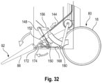
- the cable 144 When the side assembly 16 is unfolded, the cable 144 is pulled at the first end in the direction of the Fig. 30 The cable 144 is pulled in the direction of the arrow shown. Since the cable 144 is connected to the first lever element 148 of the toggle lever 146, the first lever element 148 is pulled in the same direction. In the process, the toggle lever 146 is gradually stretched. In other words, the angle formed by the first lever element 148 and the second lever element 150 increases the more the cable 144 is pulled.
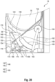
- Fig. 30 shows the initial state of the unfolding movement, in which the side assembly 16 is in the folded position 76 and the wheel and the support are each arranged in the folded position and the first toggle lever 146 is completely angled.
- Fig. 31 shows an intermediate state of the unfolding movement in which the side assembly 16 is partially unfolded and the wheel and the support are each partially unfolded and the first toggle lever 146 is partially extended.
- Fig. 32 shows the final state of the unfolding movement, in which the side assembly 16 is in the unfolded position 80 and the wheel and the support are each in the unfolded position and the first toggle lever 146 is fully extended.
- the closing movement of the side assembly 16 also proceeds accordingly.
- the cable 144 is relaxed, so that the spring element, which is arranged at the second end of the cable 144, due to the restoring force, moves the cable 144 against the direction of the Fig. 30 shown arrow.
- the second cable is thereby released, so that the spring element 180 pulls the cable 168 toward the second end. Since a pulling movement of the cable 168 is coupled with a pivoting movement of the third arm 124 and the third lever 174, the wheel 18 and the support 88 are thereby folded in.
- a mechanism is shown by which the handle 20 can be extended and retracted.
- the handle 20 can be moved between the retracted position 104 and the extended position 106 by means of this mechanism.
- the handle 20 has a handle bar 182 and a handle extension 184 at each end of the handle bar 182.
- the handle bar 182 is provided so that a user of the trolley can grasp the handle 20 at the handle bar 182 to move the trolley.
- the handle bar 182 extends in the x-direction, and each handle extension 184 extends in the y-direction.
- the handle extensions are thus arranged parallel to one another.
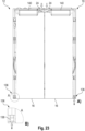
- the base assembly 14 has a drawer 186 in which the two handle extensions 184 can be arranged.
- the drawer 186 also extends in the y-direction.
- the handle extension 184 can be inserted into or pulled out of the drawer 186.
- actuating element 22 is actuated to extend the handle 20. This releases the locking of the handle 20 in the drawer 186, so that the handle can be moved from the retracted position 104 to the extended position 106 along the y-direction.
- actuating element 22 is also actuated to insert the handle 20. This releases the locking of the handle 20 in the drawer 186, so that the handle can be moved from the extended position 106 to the retracted position 104 along the y-direction.
- Fig. 35 shown how the transport carriage 10 is transformed or transferred from the first operating mode 86 to the second operating mode 126.
- the transformation is effected by a pivoting movement of the handle 20.
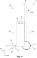
- the handle in the extended position 106, the handle is pivotable relative to the base assembly 14 about a pivot axis 194 that runs parallel to the x-direction.
- the handle 20 is moved, for example, from a first pivot position 188 to a second pivot position 190.
- a movement in one direction of rotation about the pivot axis 194 is used for the transformation.
- a pivoting movement from the first pivot position 188 to the second pivot position 190 is used for the transformation, while a movement of the handle in the opposite direction is not used.
- a movement in one direction of rotation about the pivot axis 194 from the first pivot position 188 to the second pivot position 190 is coupled with a movement of each support wheel 100 and the first receptacle 93 in order to transfer the support wheel 100 from the folded position 118 to the unfolded position 128 and to transfer the first receptacle 93 from the transport position 108 to the loading position 110.
- this pivoting movement is also partially coupled with the pivoting movement of the wheels 18 and the support 88 in order to transfer the wheels 18 from the first unfolded position 78 to the second unfolded position 132 and to transfer the supports 88 from the unfolded position to the folded-back position 134.
- a movement in an opposite direction of rotation about the pivot axis 194 from the second pivot position 190 to the first pivot position 188 is not coupled with the movements of the support wheel 100, each wheel 18, each support 88 and the first support 93.
- the handle 20 is moved one or more times from the first pivot position 188 to the second pivot position 190 or between the first and second pivot positions 188, 190.
- the support wheels 100 are pivoted from the folded-in position 118 to the unfolded position 120
- the receptacle 94 is pivoted from the transport position 108 to the loading position 110
- the wheels 18 are pivoted from the first unfolded position 78 to the second unfolded position 132
- the supports 88 are pivoted from the unfolded position 92 to the folded-back position.
- the second toggle lever 165 is extended.
- the first actuating element 22 can be arranged in a locking position 217, a free-rotation position 215, and a coupling position 219. In the locking position 217, the first actuating element 22 is not actuated. In the free-rotation position 215, the first actuating element 22 is transferred by pressing the actuating element 22 in. The first actuating element 22 is transferred to the coupling position 219 by laterally displacing the actuating element 22.
- the handle 20 is pivotally mounted on the base assembly 14 via a coupling mechanism 192 about the pivot axis 194, which runs parallel to the x-direction.
- the coupling mechanism 192 is coupled to the actuating element 22.
- the coupling mechanism 192 is, as described below with reference to Fig. 39 to 41 explained, into a locked state 216, in which the handle 20 cannot be pivoted relative to the base assembly 14, a coupled state 218, in which the handle 20 can be pivoted relative to the base assembly 14 and a pivoting movement of the handle 20 can be transmitted, and a free-rotation state 214, in which the handle 20 can be pivoted relative to the base assembly 14 and a pivoting movement of the handle 20 cannot be transmitted.
- the coupling mechanism 192 assumes the locked state 216 when the first actuating element 22 is brought into the locking position 217.
- the coupling mechanism 192 assumes the coupling state 218 when the first actuating element 22 is brought into the coupling position 219.
- the coupling mechanism 192 assumes the free-rotation state 214 when the first actuating element 22 is brought into the free-rotation position 215.
- the coupling mechanism 192 is preloaded in the locking position 216.
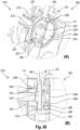
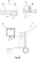
- the first actuating element 22 When transferring the transport carriage 10 from the first operating mode 86 to the second operating mode 126, first, as shown in views (B) and (C) of the Fig. 36 is shown, the first actuating element 22 is moved from the locking position 217 into the free-rotation position 215 so that the handle 20 can be pivoted about the pivot axis 194, for example into the first pivot position 188. Then, as shown in view (D) of the Fig. 36 As shown, the first actuating element 22 is moved into the coupling position 219 so that the pivoting movement can be transmitted and used to transform the transport carriage 10.
- the handle 20 is then moved one or more times from the first pivot position 188 to the second pivot position 190 or between the first and second pivot positions 188, 190 in order to transfer the transport carriage 10 from the first operating mode 86 to the second operating mode 126. Finally, the actuating element 22 is moved into the locking position 217 so that the handle 20 can no longer be pivoted.
- Fig. 37 It is shown how the transport carriage is transferred from the second operating mode 126 to the first operating mode 86.
- the actuating element 22 is transferred or brought from the locking position 217 into the coupling position 219, whereby a pivoting movement of the handle 20 can be transmitted via the coupling mechanism 192.
- the handle 20 is then moved one or more times from the first pivot position 188 to the second pivot position 190 or between the first and second pivot positions 188, 190.
- the support wheels 100 are pivoted from the unfolded position 120 to the folded position 118, the receptacle 94 is pivoted from the loading position 110 to the transport position 108, the wheels 18 are pivoted from the second unfolded position 132 to the first unfolded position 78, and the supports 88 are pivoted from the folded-back position 134 to the unfolded position 92.
- the second toggle lever 165 is bent. Then, as shown in views (B) and (C), the actuating element 22 is moved into the free-rotation position 215 so that the handle 20 can be pivoted into the extended position 106. Finally, the actuating element 22 is moved into the locking position 217 so that the handle 20 can no longer be pivoted.
- the handle 20 may further comprise a locking device which holds the first actuating element 22 in the coupling position 219 or the coupling mechanism in the coupling state until the first operating mode 86 or the second operating mode 126 is reached when the transport carriage 10 is transferred.
- Fig. 38 It is shown again how the handle height of the handle 20 can be adjusted when the trolley 10 is arranged in the second operating mode.
- the first actuating element 22 is moved from the locking position 217 to the free-rotation position 219 so that the handle 20 can be pivoted relative to the base assembly 14 about the pivot axis 194 in order to adjust the desired handle height. Since the pivot axis 194 runs parallel to the x-direction, the pivot axis 194 is a horizontal axis. The handle height can thus be adjusted by pivoting the handle 20 about the pivot axis 194. Finally, the actuating element 22 is moved into the locking position 217 so that the handle 20 can no longer be pivoted.
- the coupling mechanism 192 of the transport carriage 10 is shown in detail.
- the base assembly 14 has such a coupling mechanism on each side at the top end of each drawer 186.
- the coupling mechanism 192 has a base body 195.
- the base body 195 is firmly or rigidly connected to a lower end of the handle extension 184 of the handle 20.
- the base body 195 is rotatably mounted in the base assembly 14 about the pivot axis 194.
- the base body 195 has first projections 200 on a first side and second projections 204 on a second side. The first side and the second side are arranged opposite one another in the x-direction.
- the first projections 200 and the second projections 204 are each distributed symmetrically about the pivot axis 194.
- the base assembly 15 has a locking element 209.
- the locking element 209 is arranged on one side of the base body 195 in an axial direction of the pivot axis 194.
- the locking element 209 is rigidly connected to the base assembly.
- the locking element 209 has first recesses 202, which are complementary to the first projections 200.
- the projections 200 are thus arranged on the side of the base body 195 facing the locking element 209.
- the first recesses 202 are also distributed symmetrically around the pivot axis 194.
- all first projections 200 are identically shaped, with each first recess 202 having a profile complementary to the first projections 200.
- the coupling mechanism 192 can be coupled to an actuating element 197 of an actuating device 199, which is also rotatably mounted in the base assembly 14 about the pivot axis 194.
- the actuating element 197 is arranged in the axial direction of the pivot axis 194 on a side of the base body 195 opposite the locking element 209.
- the base body 195 is arranged between the actuating element 197 and the locking element 209 in the axial direction of the pivot axis 194.
- the actuating element 197 has second recesses 206 that are complementary to the second projections 204.
- the second recesses 206 are also distributed symmetrically around the pivot axis 194.
- all second projections 204 are identically shaped, with each second recess 206 having a profile complementary to the second projections 204.
- the coupling mechanism 192 further includes a first profiled disc 196.
- the first profiled disc 196 is arranged coaxially with the pivot axis 194.
- the first cable 198 is coupled to the first profiled disc 196, so that a pulling movement of the cable 198 is transmitted to a rotational movement of the profiled disc 196 about the pivot axis 194.
- the coupling mechanism 192 further includes a second profiled disc 210.
- the second profiled disc 210 is arranged coaxially with the pivot axis 194.
- the second cable 212 is coupled to the second profiled disc 210, so that a pulling movement of the cable 212 is transmitted to a rotational movement of the profiled disc 210 about the pivot axis 194.
- the first and second profile discs 196, 210 can each be pretensioned by a respective spring device against the pulling direction of the cables 198, 212.
- the first profile disc 196 and the second profile disc 210 are arranged in the base body.
- the base body 195 surrounds the profile discs 196, 210.
- the profile discs 196, 210 are rotatable relative to the base body 195 about the pivot axis 194.
- the first profile disc 196, the second profile disc 210, and the base body 195 are coupled to one another parallel to the pivot axis, preferably in a form-fitting manner, so that the first profile disc 196, the second profile disc 210, and the base body 195 are jointly movable parallel to the pivot axis 194.
- the first and second profiled discs 196, 210 are spaced apart from one another in the direction of the pivot axis 194, in particular arranged side by side.
- the first profiled disc 196 is arranged closer to the first recesses 202 than the second profiled disc 210, and the second profiled disc 210 is accordingly arranged closer to the second recesses 206 than the first profiled disc 196.
- the sleeve is arranged in the axial direction of the pivot axis 194 between the actuating element 197 and the locking element 209 and rests in the axial direction of the pivot axis 194 against both the actuating element 197 and the locking element 209, so that the sleeve 203 is supported or held in the axial direction of the pivot axis 194 by the actuating element 197 and the locking element 209.
- the pitch of the threaded portion 207 is greater than the pitch of the threaded portion 205.
- the first actuating element 22 is transferred from the locked position 217 to the free-rotation position 215.
- the first cable 198 is pulled, causing the profiled disc 196 to rotate.
- the profiled disc 196 and the base body 195 are pushed by the locking element 209 toward the actuating element 197, so that both the first projections 200 are disengaged from the first recesses 202 and the second projections are disengaged from the second recesses 206.
- the first actuating element 22 is transferred from the locked position 217 or from the free-rotation position 215 to the coupling position 219. In doing so, the second cable 212 is pulled, thereby rotating the profiled disc 210.
- the profiled disc 210 and the base body 195 are pushed by the locking element 209 in the direction of the actuating element 197, so that both the first projections 200 are disengaged from the first recesses 202 and the second projections are engaged with the second recesses 206.
- the locking device arranged in the handle 20 can be designed to clamp the cable 212 such that the coupling mechanism 192 is held in the coupling state 219 until the first operating mode 86 or the second operating mode 126 is reached when the transport trolley 10 is transferred.
- the locking device is activated when the first actuating element 22 is transferred into the coupling position 219.
- Such a locking device 290 and a corresponding unlocking device 280 for unlocking the locking device 290 are described with reference to Fig. 49 and 50 be described in more detail.
- the actuating element 197 is coupled to one end of a cable 208 of the actuating device 199, so that the cable 208 is pulled or tensioned by a rotational movement of the actuating element 197 in one direction of rotation about the rotation axis 194.
- the cable 208 is pulled in a first direction of movement.
- the other end of the cable 208 is coupled to a spring device that is tensioned when the cable 208 is pulled in the first direction of movement. If the actuating element 197 is rotated in the opposite direction of rotation, the cable 208 is released and pulled against the first direction of movement by the restoring force of the spring device. The cable 208 is thus moved either in or against the first direction of movement, depending on the direction of rotation of the actuating element 197.
- the cable pulls 208 are jointly coupled to a movement conversion device 264, which is described below with reference to the Figures 42 to 51 is described in detail.
- the actuating device 199 further includes the motion conversion device 264.
- the motion conversion device 264 is configured to convert a movement of each cable pull 208 in the first direction of movement into a second movement, by means of which the transformation between the first operating mode 86 and the second operating mode 126 takes place. The second movement thus drives the pivoting movements of the support wheels 100 and the first receptacle 93.
- the actuating device 199 may comprise a translation device 220.
- a translation device 220 Embodiments of a translation device 220 are described, for example, in the Figures 42 and 43 shown.
- the transmission device 220 is coupled to the cable pulls 208 and, depending on the transmission ratio, converts a movement of the cable pulls into rotary movements of varying strengths.
- the transmission ratio is determined by the force with which the cable pull 208 is pulled.
- the transmission device is designed to provide a corresponding transmission ratio depending on the force with which the cable pulls 208 are pulled.
- the force to be applied depends, for example, on the weight of a transport box arranged in the first receptacle 93.
- the tensile force with which the cable pull 208 must be pulled also increases accordingly.
- the actuating device 199 can have a freewheel device.
- the freewheel device can be arranged, for example, between the transmission device 220 and the movement conversion device 264.
- the freewheel device can be designed to transmit a rotational movement of the translation device 220 corresponding to the first direction of movement to the movement conversion device 264 and not to transmit a rotational movement of the translation device 220 opposite to the first direction of movement to the movement conversion device 264.
- the movement conversion device 264 can also be coupled directly to the cable pull 208 via a freewheel device, wherein the freewheel device only transmits the movement of the cable pull 208 in the first direction of movement to the movement conversion device 264 and does not transmit the movement of the cable pull 208 opposite to the first direction of movement to the movement conversion device 264.
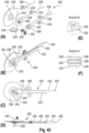
- Fig. 42 shows various views of a first embodiment of a transmission device 220.
- View (A) shows an exploded view of the transmission device 220
- view (B) an isometric view of the transmission device 220
- view (C) a side view of the transmission device 220
- view (D) a top view of the transmission device 220
- view (E) a detailed view of a disc 242 of the transmission device 220
- view (F) a detailed view of view (D) in which the discs 238, 240, 242 of the transmission device 220 are shown enlarged.
- the transmission device 220 further includes a first traction cable 226, a second traction cable 228, and a third traction cable 230.
- a first end of each traction cable 226, 228, 230 is attached to a second side of the coupling element 224.
- the transmission device 220 further comprises a first deflection pulley 232, a second deflection pulley 234, and a third deflection pulley 236.
- the deflection pulleys 232, 234, 236 are identically constructed, have a common axis of rotation, and are arranged next to each other in the direction of the axis of rotation.
- the first traction cable 226 is deflected around the first deflection pulley 232
- the second traction cable 228 is deflected around the second deflection pulley 234, and the third traction cable 230 is deflected around the third deflection pulley 236.
- the three traction cables 226, 228, and 230 run parallel to each other up to the deflection pulleys 232, 234, and 236.
- the transmission device 220 further includes a first disk 238, a second disk 240, and a third disk 242.
- the first disk 238 has a larger diameter than the second disk 240.
- the second disk 240 has a larger diameter than the third disk 242.
- the three disks 238, 240, and 242 share a common axis of rotation and are arranged side by side in the direction of the axis of rotation.
- the three disks are rotatably mounted on an axle 244.
- the pulleys 238, 240, 242 are rotated by different angles of rotation during a joint pulling movement of the traction cables 226, 228, 230.
- the angle of rotation of the first pulley 238 is smaller than the angle of rotation of the second pulley 240, and the angle of rotation of the second pulley 240 is smaller than the angle of rotation of the third pulley 242.
- the first pulley 238 can be coupled to the motion conversion device 264 via a freewheel device.
- the first disc 238 has recesses 246 on the side facing the second disc 240, which are distributed in the circumferential direction.
- the second On the side facing the first disc 238, disc 240 has projections 248 that are arranged and shaped complementarily to the recesses 246. The recesses 246 and the projections 248 can be brought into engagement with one another.
- the second disc 240 has recesses 250 on the side facing the third disc 242, which are arranged distributed in the circumferential direction.
- the third disc 242 has projections 252 on the side facing the second disc 240, which are arranged and shaped complementarily to the recesses 250. The recesses 250 and the projections 252 can be brought into engagement with one another.
- the transmission device 220 further comprises a spring element 256, for example a spiral spring, by means of which the three discs are pressed against one another in the direction of the axis 244, so that the projections 248 and 252 are brought into engagement with the corresponding recesses 246 and 250.
- a spring element 256 for example a spiral spring
- the transmission device 220 further includes another deflection pulley 254.
- the third traction cable 230 extends from the coupling element 224, first to the third deflection pulley 236, then to the third disc 242, from the third disc 242 to the deflection pulley 254, and from the deflection pulley 254 to a spring device (not shown).
- a second end of the third traction cable is connected to the spring device. A pulling movement of the third traction cable 230 directed from the second end to the first end tensions the spring device.
- the projections 248 and 252 each have a straight flank and a slanted flank.
- the straight flank and the slanted flank are arranged on opposite sides of the respective projection 248, 252 in the circumferential direction, wherein the slanted flanks are arranged upstream of the straight flank in a pulling direction of the pull cables 228, 230 from the respective second end toward the first end, in particular in the resulting direction of rotation of the respective disk.
- the third pulley 242 is rotated by a larger angle than the second pulley 240 and the second pulley 240 by a larger angle than the first pulley 238.
- the first and second pulleys 238, 240 are rotated by the same angle as the third pulley 242 via the third pulley, so that the first and second pulleys 226, 228 are relaxed during a rotating movement, in particular so that the first and second pulleys 226, 228 sag.
- a pulling movement by the cable 222 is transmitted via the third pulling cable 230 and the third disc 242 to a rotational movement of the first disc 238.
- a rotational angle of the rotational movement of the first disc 238 and a pulling distance of the pulling movement of the cable 222 or the third cable 230 have a third transmission ratio.
- the transmission ratio indicates the ratio of the rotational angle to the pulling distance.
- the third pulley 242 can be disengaged from the second pulley 240 against the pretensioning force of the spring element 256.
- the third pulley 242 is freely rotatable and the second pull cable 228 is tensioned, so that a pulling movement by the cable pull 222 is transmitted via the second pull cable 228 and the second pulley 240 to a rotary movement of the first pulley 238.
- a rotation angle of the rotary movement of the first pulley 238 and a pulling distance of the pulling movement of the cable pull 222 or the second cable pull 228 have a second transmission ratio that is smaller than the third transmission ratio.
- the second disk 240 can be disengaged from the first disk 238 against the pretensioning force of the spring element 256.
- the second disk 240 is also freely rotatable and the first pull cable 226 is relaxed, so that a pulling movement by the pull cable 222 is transmitted via the first pull cable 226 to a rotational movement of the first disk 238.
- a rotational angle of the rotational movement of the first disk 238 and a pulling distance of the pulling movement of the pull cable 222 or the first pull cable 226 have a first transmission ratio that is smaller than the second transmission ratio.
- the transmission ratio of the transmission device 220 can be automatically controlled depending on the pulling force applied to the cables.
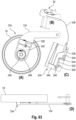
- Fig. 43 shows a second embodiment of a translation device 220' in a schematic representation.
- the translation device 220' is arranged in the base assembly 14, in particular in an upper part of the base assembly 14.
- the translation device 220' has essentially the same components as the translation device 220.
- Fig. 42 The difference to the translation device 220 from Fig. 42 is that the transmission device 220' has only two discs 238, 240 instead of three. In principle, any number of more than one disc can be provided, with the discs each being engageable with one another via complementarily shaped recesses and projections.
- the cable pull 222 is connected to two cables 258 and 260.
- the cable pull 258 can, for example, correspond to the cable pull 208 of a first coupling mechanism 192 on one side of the base assembly 14 and the cable pull 260 can, for example, correspond to the cable pull 208 of a second coupling mechanism 192 on an opposite side of the base assembly 14.
- one of the two cable pulls in this case the cable pull 260, can be guided to the opposite side of the base assembly 14 by means of deflection pulleys 262.
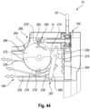
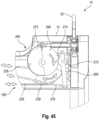
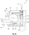
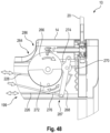
- the Figures 44 to 48 show a first embodiment of a motion conversion device 264.
- the motion conversion device 264 has a disc 266 and a lever 268.
- the disc is rotatably mounted in the base assembly 14 with respect to a rotation axis.
- the disk 266 is not rotationally symmetrical with respect to the axis of rotation. Instead, the disk 266 has a radial profile that changes along a circumferential direction of the disk 266. In other words, the radius of the disk 266 changes along the circumferential direction.
- the radial profile is preferably oval and has an axis of symmetry. As a result, the radial profile is mirror-symmetrical.
- the oval radial profile intersects the axis of symmetry at a first point and a second point, wherein the first point has the smallest radius, in particular distance from the axis of rotation, and the second point has the largest radius.
- the two points are spaced 180° from each other around the axis of rotation.
- the radius increases continuously along the circumference of the disk 266 from the first point to the second point.
- a first end of the lever 268 is pivotally mounted in the base assembly.
- the lever includes a wheel 270 rotatably mounted on the lever 268 between the first end and a second end of the lever 268.
- the mounting point of the wheel 270 is located closer to the first end of the lever 268 than to the second end of the lever 268.
- the wheel 270 rests against the circumferential surface of the disc 266.
- the wheel 270 is designed to roll along the circumferential surface when the disc 266 rotates. Because the disc is oval and thus the radial profile changes along the circumferential direction, the wheel is offset in a radial direction relative to the axis of rotation of the disc 266 when the disc 266 is rotated. This causes the lever to deflect or pivot about its bearing point in the base assembly 14. In other words, an incline or decline in the radial profile of the disc 266 causes the lever to deflect when the disc rotates. As a result, the lever 268 performs a pendulum or oscillating movement when the disc 266 is rotated.
- the second end of the lever 268 is connected to a first end of a cable 276.
- a second end of the cable 276 is coupled to a spring element.
- the cable 276 is pulled or tensioned in a second direction of movement or relaxed counter to the second direction of movement.
- the spring element is also tensioned.
- the cable 276 is pulled counter to the second direction of movement due to the restoring force of the spring element.
- the pendulum movement of the lever 268 causes the cable 276 to be moved alternately in and counter to the second direction of movement.
- the disc 266 further includes a crescent-shaped protrusion 272 on one side of the axis of symmetry, which also has the same radial profile on this side of the axis of symmetry.
- the lever 268 further includes a braking protrusion 274.
- the braking protrusion 274 extends from the bearing point of the wheel 270 toward the disc 266.
- the braking protrusion 274 is preferably semicircular and extends the same distance toward the disc 266 as the wheel 270.
- the disc 266 is connected to the transmission device 220' via a freewheel device, so that the disc is driven in only one direction of rotation.
- a rotational movement of the actuating element 197 in the first direction of movement is transmitted to the disc 266 via the cable 208, the transmission device 220', and the freewheel device, whereas a rotational movement of the actuating element 197 opposite to the first direction of movement is not transmitted to the disc 266 due to the freewheeling of the freewheel device.
- the disc 266 is arranged in a first rotational position 286.
- the wheel 270 is arranged at the first point of the radial profile of the disc 266.
- the lever 268 is arranged in a first end position 287.
- the transport carriage is arranged in the first operating mode 86 when the disc 266 is arranged in the first rotational position 286.
- the disc 266 is arranged in the second rotational position 288.
- the wheel 270 is arranged at the second point of the radial profile of the disc 266.
- the lever 268 is arranged in the second end position 289.
- the transport carriage is arranged in the second operating mode 126 when the disc 266 is arranged in the second rotational position 288.
- the flap 282 In a rest position of the spring element, the flap 282 is not deflected by one of the pins 278 and the rod 292 is accordingly not displaced in the direction of the coupling mechanism 192.
- the spring element thus causes the flap 282 to be preloaded into a non-deflected position.
- Figures 49 and 50 the flap 282 is arranged in the undeflected position.
- the rod 292 is coupled to the unlocking element 302 via a first deflection element 294 and a second deflection element 300.
- the rod 292 rests on the first deflection element 294.
- the first deflection element 294 is movable parallel to the pivot axis 194.
- the rod can thus displace the first deflection element 294 parallel to the pivot axis 194.
- the second deflection element 300 rests on the unlocking element 302.
- the second deflection element 300 is arranged perpendicular to the pivot axis 194 and parallel to the direction of extension of the handle extension 184.
- the second deflection element 300 can thus displace the unlocking element parallel to the extension direction of the handle extension 184.
- the unlocking element 302 can also be preloaded against the second deflection element 300 by means of a spring
- the first deflection element 294 has a first oblique flank 296 and the second deflection element 300 has a second oblique flank 298.
- the first oblique flank 296 and the second oblique flank 298 are shaped complementarily to each other.
- the two deflection elements 294, 300 are coupled to each other via the oblique flanks 296, 298. In particular, this is also referred to as an oblique flank coupling.
- the second deflection element 300 is displaced perpendicular to the pivot axis 194, in particular parallel to the direction of extension of the handle extension 184.
- the unlocking element 302 is coupled to the locking device 290 in such a way that the clamping of the locking device 290 is released by the displacement of the unlocking element 302.
- the corresponding pin 278 pushes the flap to the side and thus displaces the rod 292 parallel to the pivot axis 194 in the direction of the first deflection element 294.
- the first deflection element 294 is also displaced, so that the second deflection element 300 is pushed via the inclined flank coupling in the direction of the unlocking element 302.
- the unlocking element 302 is also displaced, so that the clamping of the locking device 290 is released.
- the cable pull 212 is released again, and the first actuating element 22 is moved back into the free-rotation position 215 or the locking position 217, so that the coupling mechanism 192 is no longer arranged in the coupled state 218.
- Fig. 51 shows a second embodiment of a motion conversion device 264'.
- the motion conversion device 264' basically has the same structure as the motion conversion device 264. The difference lies in the different design of the lever 268 and the disc 266.
- the braking projection 274' of the lever 268' is not semicircular but angular.
- the braking projection 274' extends further in the direction of the disc 266' than the wheel 270'.
- the elevation 272' has a radial profile that is similar to the disc 266', wherein the elevation is offset inwardly with respect to the axis of rotation by the same length that the braking projection 274' extends further in the direction of the disc 266' than the wheel 270'.
- the arm 96 is rotatably mounted on the corresponding side assembly 16 via a roller 306 so that the corresponding receiving element 94 can be moved between the transport position 108 and the loading position 110.
- a cable 308 is coupled to the pulley 306.
- a first end of the cable 308 is attached to the pulley 306, so that a pulling movement toward a second end of the cable 308 rotates the pulley 306 about its axis of rotation.
- the second end of the cable 308 is coupled to the cable 276 of the motion conversion device 264 such that a movement of the cable 276 in the second direction of movement is transmitted to the cable 308.
- the cable 308 preferably extends from the side assembly 16 into the base assembly 14.
- the roller 306 can also be coupled to a spring device that is tensioned when the cable 308 is pulled towards the second end, in particular in the second direction of movement. If the cable 276 is moved in the second direction of movement by means of the lever 268, the cable 308 is also pulled in the second direction of movement. As a result, the arm 96 is pivoted from the transport position 108 towards the loading position 110 and the spring device is tensioned. If the cable 276 is moved counter to the second direction of movement by means of the lever 268, the cable 308 is released again, whereby the restoring force of the spring device causes the cable 308, and thus also the cable 276, to be pulled counter to the second direction of movement.
- the receiving element 94 is rotatably mounted on the arm 96 by means of a roller 310.
- the arm 96 further comprises a circumferential cable or belt 312 that encircles the roller 306 and the roller 310.
- the rollers 306 and 310 have the same circumference. This ensures that, when the arm 96 is pivoted, the receiving element 94 always has the same orientation in space, particularly with respect to the vertical direction.
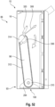
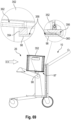
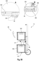
- Fig. 52 The transport carriage 10 is arranged in the first operating mode 86.
- the first receiving element 94 is thus arranged in the transport position 108.
- the disc 266 is arranged in the first rotational position 286.
- the cable pull 308 is pulled in the second direction of movement. This rotates the roller 306 in one direction about the axis of rotation, causing the arm 96 to pivot upwards above the roller 306. This changes the vertical position of the receiving element 94, while the orientation of the receiving element 94 remains unchanged.
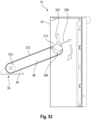
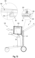
- Fig. 53 For example, the transport carriage 10 is in a state between the first operating mode 86 and the second operating mode 126.
- the first receptacle 93 is arranged between the transport position 108 and the loading position 110.
- the receiving element 94 is pivoted upwards until it reaches the loading position 110.
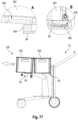
- the loading position 110 is reached when the disk 266 is arranged in the second rotational position 288. This state is shown in Fig. 54 shown.
- the transport carriage 10 is thus arranged in the second operating mode 126.
- the cable pull 308 is moved counter to the second direction of movement. This rotates the roller 306 about the axis of rotation in an opposite direction of rotation, causing the arm 96 to pivot downward above the roller 306. This changes the vertical position of the receiving element 94, while the orientation of the receiving element 94 remains the same.
- the receiving element 94 is pivoted downward until it reaches the transport position 108.
- the transport position 108 is reached when the disk 266 is arranged in the first rotation position 286.
- the transport carriage is then arranged again in the first operating mode 86.
- a movement of the first receptacle 93 is coupled with a movement of the support wheels 100. This coupling is shown in the Figures 55 to 57 described in detail.
- the roller 306 has a slotted guide 314.
- the slotted guide 314 has a first, straight section 316, which runs eccentrically from the radial inside to the radial outside with respect to the axis of rotation.
- the slotted guide has a second, curved section 318, which adjoins the first section 316.
- the second section 318 extends along the circumference of the roller 306, with a radial distance of the slotted guide 314 along the second section 318 steadily increasing, starting from the first section 316.
- the radial pitch of the slotted guide 314 is greater in the first section 316 than in the second section 318.
- a lever 320 is arranged on the side assembly 16.
- a first end of the lever 320 is pivotally mounted on the side assembly about a pivot axis.
- the pivot axis runs parallel to the rotational axis of the roller 306.
- the pivot axis is arranged above the rotational axis of the roller 306 in the y-direction.
- a wheel 322 is rotatably mounted on a second end of the lever 320. The wheel rests against the slotted guide 314 and can roll along the slotted guide 314 when the roller 306 is rotated.
- the lever 320 is bent. To this end, the lever 320 has a first straight section 324 and a second straight section 326, which are arranged at an angle to one another. The first end of the lever 320 is arranged on the first section 324, and the second end of the lever 320 is arranged on the second section 326.
- the lever 320 is coupled to another cable 328.
- the cable 328 is attached to the second section 326 of the lever 320. A movement of the cable 328 causes the support wheels to be folded out or folded in.
- FIG. 56 This condition is in Fig. 56
- the wheel is arranged at the beginning of the second section 318.
- the transport carriage 10 is in a state between the first operating mode 86 and the second operating mode 126, and the first receptacle 93 is arranged between the transport position 108 and the loading position 110.
- the roller 306 continues to rotate as described above until the second operating mode 126 is reached. In doing so, the wheel rolls along the second section 318.
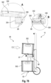
- the wheel 322 is arranged at one end of the second section 318. This state is shown in Fig. 57 shown.
- a radial distance of the slotted guide 314 with respect to the axis of rotation of the roller 306 along the slotted guide 314 increases continuously from the beginning of the first section 316 to an end of the second section 318, a radial distance of the wheel 322 from the axis of rotation of the roller 306 also changes. This deflects the lever 320, causing the lever 320 to pull on the cable 328. Due to the different radial gradients in the first section 316 and the second section 318, the lever is deflected further when the wheel 322 moves along the first section 316 than when the wheel 322 moves along the second section 318.
- the ratio of the deflections corresponding to the two sections is preferably 1:2 to 1:10, in particular 1:5.
- the roller 164 is coupled to the cable 328.
- the cable 328 is attached to the roller 164 so that the roller 164 is rotated when the cable 328 is pulled.
- the rotational movement of the roller 306, in particular the pivoting movement of the first receptacle is coupled to the rotational movement of the roller 164 via the lever 320 and the cable 328.
- the roller 164 can further be coupled to a spring device that is tensioned when the cable 328 is pulled. If the cable 328 is released, the roller 164 is rotated back due to the restoring force of the spring device, whereby the cable 328 is pulled in the opposite direction.
Landscapes
- Engineering & Computer Science (AREA)
- Chemical & Material Sciences (AREA)
- Combustion & Propulsion (AREA)
- Transportation (AREA)
- Mechanical Engineering (AREA)
- Handcart (AREA)
Claims (9)
- Chariot de transport (10) comportant un module de base (14), comportant deux modules latéraux (16) disposés sur le module de base (14) et opposés l'un à l'autre et comportant respectivement une roue (18) disposée sur respectivement l'un des modules latéraux (16), dans lequel le chariot de transport (10) peut être transféré entre un mode d'emballage (12) dans lequel chaque roue (18) est disposée dans une position rentrée (74) et chaque module latéral (16) est disposé dans une position repliée (76), et un premier mode de fonctionnement (86) dans lequel chaque roue (18) est disposée dans une position déployée (78) et chaque module latéral (16) est disposé dans une position dépliée (80), dans lequel un déplacement de chaque module latéral (16) entre la position repliée (76) et la position dépliée (80) est accouplé à un déplacement de la roue (18) correspondante entre la position rentrée (74) et la position déployée (78), de sorte que, lors du déplacement de chaque module latéral (16) entre la position repliée (76) et la position dépliée (80), la roue (18) correspondante est déplacée entre la position rentrée (74) et la position déployée (78), dans lequel le chariot de transport (10) présente en outre un support (88) sur chaque module latéral (16).
- Chariot de transport (10) selon la revendication 1, dans lequel chaque support (88) est disposé dans une position rentrée (90) dans le mode d'emballage (12) et dans une position déployée (92) dans le premier mode de fonctionnement (86).
- Chariot de transport (10) selon la revendication 2, dans lequel le déplacement de chaque module latéral (16) entre la position repliée (76) et la position dépliée (80) est accouplé à un déplacement du support (88) correspondant entre la position rentrée (90) et la position déployée (92).
- Chariot de transport (10) selon l'une des revendications 1 à 3, dans lequel le chariot de transport (10) présente en outre un appareil de blocage (136) réalisé pour bloquer chaque module latéral (16) dans la position repliée (76) et dans la position dépliée (80), dans lequel le chariot de transport (10) présente en outre au moins un second élément d'actionnement (24) au moyen duquel le blocage des modules latéraux (16) provoqué par l'appareil de blocage (136) peut être libéré.
- Chariot de transport selon l'une des revendications 1 à 4, dans lequel le déplacement de chaque support (88) et/ou de chaque roue (16) est accouplé au déplacement du module latéral (16) correspondant par l'intermédiaire d'un levier coudé (146), dans lequel chaque levier coudé (146) est disposé, en particulier disposé de manière étirée, dans la position déployée (78, 92) de la roue (18) correspondante ou du support (88) correspondant de telle sorte que la roue (18) respective ou le support (88) respectif est maintenu dans la position déployée (78, 92).
- Chariot de transport selon l'une des revendications 1 à 4, dans lequel chaque levier coudé (146) est disposé de telle sorte qu'il est étiré lors du transfert de la roue (16) ou du support (88) de la position rentrée à la position déployée et est coudé de manière correspondante lors du transfert de la roue (16) ou du support (88) de la position déployée à la position rentrée.
- Chariot de transport selon l'une des revendications 1 à 5, comportant en outre au moins un logement (93, 94) pour respectivement une boîte de transport, lequel est disposé entre les modules latéraux (16).
- Procédé (410) permettant de transférer un chariot de transport (10) entre un mode d'emballage (12) et un premier mode de fonctionnement (86), dans lequel le chariot de transport (10) présente un module de base (14), deux modules latéraux (16) disposés sur le module de base (14) et opposés l'un à l'autre, respectivement une roue (18) disposée sur respectivement l'un des modules latéraux (16) et au moins un logement (93, 94) disposé entre les modules latéraux (16) pour respectivement une boîte de transport, dans lequel le chariot de transport (10) présente en outre un support (88) sur chaque module latéral (16), dans lequel le procédé présente les étapes suivantes :- transfert (412) du chariot de transport (10) du mode d'emballage (12), dans lequel chaque roue (18) est disposée dans une position rentrée (74) et chaque module latéral (16) est disposé dans une position repliée (76), au premier mode de fonctionnement (86), dans lequel chaque roue (18) est disposée dans une position déployée (78) et chaque module latéral (16) est disposé dans une position dépliée (80), au moyen d'un déplacement des modules latéraux (16) de la position repliée (76) à la position dépliée (80), dans lequel le déplacement de chaque module latéral (16) entre la position repliée (76) et la position dépliée (80) est accouplé à un déplacement de la roue (18) correspondante entre la position rentrée (74) et la position déployée (78) ;- transfert (414) du chariot de transport (10) du premier mode de fonctionnement (86) au mode d'emballage (12) au moyen d'un déplacement des modules latéraux (16) de la position dépliée (80) à la position repliée (76).
- Procédé (420) permettant de transformer un chariot de transport (10), dans lequel le chariot de transport (10) présente un module de base (14), deux modules latéraux (16) disposés sur le module de base (14) et opposés l'un à l'autre, et respectivement une roue (18) disposée sur respectivement l'un des modules latéraux (16), dans lequel le procédé présente les étapes suivantes :- transfert (422) d'un chariot de transport (10) entre un mode d'emballage (12) et un premier mode de fonctionnement (86) conformément au procédé selon la revendication 8 ; et- transfert (424) d'un chariot de transport (10) entre le premier mode de fonctionnement (86) et un second mode de fonctionnement (126),dans lequel l'étape de transfert (424) du chariot de transport (10) entre le premier mode de fonctionnement (86) et le second mode de fonctionnement (126) présente les étapes suivantes :- transfert (402) du chariot de transport (10) du premier mode de fonctionnement (86) au second mode de fonctionnement (126) au moyen d'un premier actionnement, dans lequel un élément d'actionnement (197) d'un dispositif d'actionnement (199) du chariot de transport (10) est déplacé dans une première direction de déplacement ; et- transfert (404) du chariot de transport (10) du second mode de fonctionnement (126) au premier mode de fonctionnement (86) au moyen d'un second actionnement, dans lequel l'élément d'actionnement (197) est déplacé dans la première direction de déplacement.
Applications Claiming Priority (3)
| Application Number | Priority Date | Filing Date | Title |
|---|---|---|---|
| DE102019125165 | 2019-09-18 | ||
| PCT/EP2020/072684 WO2021052685A1 (fr) | 2019-09-18 | 2020-08-12 | Chariot de transport et procédé pour transformer un chariot de transport |
| PCT/EP2021/055904 WO2022033726A1 (fr) | 2019-09-18 | 2021-03-09 | Chariot et procédé de transformation d'un chariot |
Publications (3)
| Publication Number | Publication Date |
|---|---|
| EP4196382A1 EP4196382A1 (fr) | 2023-06-21 |
| EP4196382B1 true EP4196382B1 (fr) | 2025-07-09 |
| EP4196382C0 EP4196382C0 (fr) | 2025-07-09 |
Family
ID=72145373
Family Applications (2)
| Application Number | Title | Priority Date | Filing Date |
|---|---|---|---|
| EP20757858.4A Active EP4031435B1 (fr) | 2019-09-18 | 2020-08-12 | Chariot de transport et procédé de transformation d'un chariot de transport |
| EP21709445.7A Active EP4196382B1 (fr) | 2019-09-18 | 2021-03-09 | Chariot de transport et procédé de transformation d'un chariot de transport |
Family Applications Before (1)
| Application Number | Title | Priority Date | Filing Date |
|---|---|---|---|
| EP20757858.4A Active EP4031435B1 (fr) | 2019-09-18 | 2020-08-12 | Chariot de transport et procédé de transformation d'un chariot de transport |
Country Status (4)
| Country | Link |
|---|---|
| US (1) | US12606225B2 (fr) |
| EP (2) | EP4031435B1 (fr) |
| AU (1) | AU2021324263B2 (fr) |
| WO (2) | WO2021052685A1 (fr) |
Families Citing this family (1)
| Publication number | Priority date | Publication date | Assignee | Title |
|---|---|---|---|---|
| GB2611065B (en) * | 2021-09-24 | 2025-06-18 | Armorgard Holdings Ltd | Trolley Apparatus |
Citations (2)
| Publication number | Priority date | Publication date | Assignee | Title |
|---|---|---|---|---|
| US6733026B1 (en) * | 2003-06-05 | 2004-05-11 | Beverly J Robberson | Folding cart |
| EP2230149B1 (fr) * | 2009-03-12 | 2015-07-29 | Peugeot Citroën Automobiles SA | Chariot de transport transformable à structure de liaison à deux quadrilatères à géométrie variable |
Family Cites Families (25)
| Publication number | Priority date | Publication date | Assignee | Title |
|---|---|---|---|---|
| DE69503484T2 (de) * | 1995-06-21 | 1998-11-19 | Moll Jaime Garcia | Zusammenfaltbarer Einkaufswagen |
| DE19707744C1 (de) | 1997-02-27 | 1998-10-22 | Rauschenberger Metallwaren Gmb | Zusammenlegbarer Transportwagen |
| US5863055A (en) * | 1997-09-03 | 1999-01-26 | Kasravi; Kasra | Personal cart |
| JP2007030856A (ja) * | 2005-07-25 | 2007-02-08 | Eiichi Kudo | 折りたたみ式ショッピングカート |
| JP4540725B2 (ja) * | 2008-06-11 | 2010-09-08 | 株式会社スワニー | 折り畳み椅子を有する鞄 |
| US20100253025A1 (en) * | 2009-03-17 | 2010-10-07 | Don Smith | Utility Hand-Truck |
| US20120242063A1 (en) * | 2011-03-22 | 2012-09-27 | Carl Bruckner | Device and System for Transporting and Dispensing Cables and Wires |
| TWM483905U (zh) * | 2013-11-18 | 2014-08-11 | Zhong-Xiu Su | 手推車 |
| US8979115B1 (en) * | 2014-08-20 | 2015-03-17 | Brett Baron | Shopping cart |
| CN104340254B (zh) * | 2014-11-07 | 2017-08-08 | 好孩子儿童用品有限公司 | 一种可二次折叠的儿童推车 |
| CN107249962B (zh) * | 2015-01-15 | 2019-08-23 | 道尔家居公司 | 具有模式转换器的装载物搬运车 |
| CN105365866A (zh) * | 2015-12-04 | 2016-03-02 | 中国人民解放军国防科学技术大学 | 一种折叠式手推车 |
| US20180065655A1 (en) * | 2016-09-02 | 2018-03-08 | The Ergo Baby Carrier, Inc. | Collapsible stroller having central hub system |
| WO2018051267A1 (fr) * | 2016-09-15 | 2018-03-22 | Albert Gaide | Chariot pliable pour faciliter les courses |
| DE102016217867B4 (de) * | 2016-09-19 | 2019-04-18 | Bundesdruckerei Gmbh | Transportvorrichtung für Gepäck und Verfahren zum Transport eines Gepäckstücks |
| US9688298B1 (en) * | 2016-10-17 | 2017-06-27 | Chung-Hsiu Su | Convertible hand truck |
| US10005481B1 (en) * | 2016-11-23 | 2018-06-26 | Albert Manuel Lopez | Dolly for field technicians |
| WO2018127409A1 (fr) | 2017-01-03 | 2018-07-12 | Buschbacher Gudrun | Voiture à bras réglable |
| EP3378727A1 (fr) * | 2017-03-24 | 2018-09-26 | HILTI Aktiengesellschaft | Chariot de transport de charges pliable |
| US9834243B1 (en) * | 2017-04-14 | 2017-12-05 | Dong Guan Jia Lian Kids Products Co., Ltd. | Collapsible baby carriage |
| US10407088B1 (en) * | 2017-10-02 | 2019-09-10 | Tu Van Anh Le | Transformable wheeled cart and method of use |
| IL260225A (en) * | 2018-06-24 | 2018-07-31 | Keter Plastic Ltd | pushcart |
| CN209079949U (zh) * | 2018-10-16 | 2019-07-09 | 广东顺和工业有限公司 | 两用折叠手推车 |
| US20200369306A1 (en) * | 2019-05-20 | 2020-11-26 | Myw Llc | Hand truck |
| US20210053600A1 (en) * | 2019-08-19 | 2021-02-25 | Illinois Enterprises Co. | Foldable multiple-function cart |
-
2020
- 2020-08-12 EP EP20757858.4A patent/EP4031435B1/fr active Active
- 2020-08-12 WO PCT/EP2020/072684 patent/WO2021052685A1/fr not_active Ceased
-
2021
- 2021-03-09 AU AU2021324263A patent/AU2021324263B2/en active Active
- 2021-03-09 WO PCT/EP2021/055904 patent/WO2022033726A1/fr not_active Ceased
- 2021-03-09 US US18/020,777 patent/US12606225B2/en active Active
- 2021-03-09 EP EP21709445.7A patent/EP4196382B1/fr active Active
Patent Citations (2)
| Publication number | Priority date | Publication date | Assignee | Title |
|---|---|---|---|---|
| US6733026B1 (en) * | 2003-06-05 | 2004-05-11 | Beverly J Robberson | Folding cart |
| EP2230149B1 (fr) * | 2009-03-12 | 2015-07-29 | Peugeot Citroën Automobiles SA | Chariot de transport transformable à structure de liaison à deux quadrilatères à géométrie variable |
Also Published As
| Publication number | Publication date |
|---|---|
| US12606225B2 (en) | 2026-04-21 |
| EP4031435B1 (fr) | 2024-10-02 |
| AU2021324263B2 (en) | 2024-11-14 |
| WO2022033726A1 (fr) | 2022-02-17 |
| EP4196382C0 (fr) | 2025-07-09 |
| EP4031435C0 (fr) | 2024-10-02 |
| US20230303141A1 (en) | 2023-09-28 |
| EP4031435A1 (fr) | 2022-07-27 |
| EP4196382A1 (fr) | 2023-06-21 |
| AU2021324263A1 (en) | 2023-03-09 |
| WO2021052685A1 (fr) | 2021-03-25 |
Similar Documents
| Publication | Publication Date | Title |
|---|---|---|
| DE19809331C1 (de) | Verfahr- und arretierbare Sammelvorrichtung | |
| EP0311936B1 (fr) | Chariot pour un brancard | |
| DE3018160C2 (de) | Fahrgestell für Klappkinderwagen | |
| DE19513520C1 (de) | Kraftfahrzeug mit einer Heckklappe, insbesondere für Mehrzweck- oder Kombiwagen | |
| DE3622521A1 (de) | Sitzaufhaengungseinrichtung | |
| DE10317960A1 (de) | Fahrzeuggepäckträger zur Lagerung von Gegenständen benachbart zur Hecktür eines Kraftfahrzeuges | |
| EP2271537B1 (fr) | Poussette repliable pour enfants et/ou poupées | |
| DE102016116682A1 (de) | Planenaufbau | |
| DE69902531T2 (de) | Vorrichtung zur handhabung von müllsammelbehältern | |
| DE102012006385A1 (de) | Verdeckgestell für einen Planenaufbau | |
| EP1522455A2 (fr) | Dispositif de protection de chargement dans les unités de transport | |
| DE19921006A1 (de) | Vorrichtung und Verfahren zum Aufrichten und/oder Zusammenfalten einer Faltbox | |
| DE19946501A1 (de) | Schwenkschiebetür | |
| DE19522381C1 (de) | Vorrichtung zur Positionierung einer Funktionsfläche | |
| WO1998043856A2 (fr) | Appareil de levage pour vehicules a moteur et attelages de vehicules, en particulier cric | |
| EP4196382A1 (fr) | Chariot et procédé de transformation d'un chariot | |
| EP2741975A1 (fr) | Conteneur de transport | |
| DE19916709C1 (de) | Kraftfahrzeugsitz | |
| EP3473580A1 (fr) | Dispositif d'embarquement | |
| DE102004008451A1 (de) | Fahrzeuggegenstandsträger | |
| DE202017100729U1 (de) | Zusammenklappbarer Transportwagen mit Transportkiste sowie zusammenlegbare Transportkiste für einen Transportwagen | |
| DE4427518C1 (de) | Fahrzeugaufbau, insbesondere für Lastkraftwagen und Anhänger, mit einer öffenbaren Seitenwand | |
| DE102014008949B4 (de) | Planenaufbau | |
| DE102021110421B3 (de) | Handwagen zum direkten Verladen in ein Kraftfahrzeug | |
| DE202024105436U1 (de) | Rampe für Transportstühle sowie Transportfahrzeug mit einer solchen Rampe |
Legal Events
| Date | Code | Title | Description |
|---|---|---|---|
| STAA | Information on the status of an ep patent application or granted ep patent |
Free format text: STATUS: UNKNOWN |
|
| STAA | Information on the status of an ep patent application or granted ep patent |
Free format text: STATUS: THE INTERNATIONAL PUBLICATION HAS BEEN MADE |
|
| PUAI | Public reference made under article 153(3) epc to a published international application that has entered the european phase |
Free format text: ORIGINAL CODE: 0009012 |
|
| STAA | Information on the status of an ep patent application or granted ep patent |
Free format text: STATUS: REQUEST FOR EXAMINATION WAS MADE |
|
| 17P | Request for examination filed |
Effective date: 20230309 |
|
| AK | Designated contracting states |
Kind code of ref document: A1 Designated state(s): AL AT BE BG CH CY CZ DE DK EE ES FI FR GB GR HR HU IE IS IT LI LT LU LV MC MK MT NL NO PL PT RO RS SE SI SK SM TR |
|
| DAV | Request for validation of the european patent (deleted) | ||
| DAX | Request for extension of the european patent (deleted) | ||
| GRAP | Despatch of communication of intention to grant a patent |
Free format text: ORIGINAL CODE: EPIDOSNIGR1 |
|
| STAA | Information on the status of an ep patent application or granted ep patent |
Free format text: STATUS: GRANT OF PATENT IS INTENDED |
|
| INTG | Intention to grant announced |
Effective date: 20240314 |
|
| GRAJ | Information related to disapproval of communication of intention to grant by the applicant or resumption of examination proceedings by the epo deleted |
Free format text: ORIGINAL CODE: EPIDOSDIGR1 |
|
| STAA | Information on the status of an ep patent application or granted ep patent |
Free format text: STATUS: REQUEST FOR EXAMINATION WAS MADE |
|
| INTC | Intention to grant announced (deleted) | ||
| GRAP | Despatch of communication of intention to grant a patent |
Free format text: ORIGINAL CODE: EPIDOSNIGR1 |
|
| STAA | Information on the status of an ep patent application or granted ep patent |
Free format text: STATUS: GRANT OF PATENT IS INTENDED |
|
| INTG | Intention to grant announced |
Effective date: 20250206 |
|
| GRAS | Grant fee paid |
Free format text: ORIGINAL CODE: EPIDOSNIGR3 |
|
| GRAA | (expected) grant |
Free format text: ORIGINAL CODE: 0009210 |
|
| STAA | Information on the status of an ep patent application or granted ep patent |
Free format text: STATUS: THE PATENT HAS BEEN GRANTED |
|
| AK | Designated contracting states |
Kind code of ref document: B1 Designated state(s): AL AT BE BG CH CY CZ DE DK EE ES FI FR GB GR HR HU IE IS IT LI LT LU LV MC MK MT NL NO PL PT RO RS SE SI SK SM TR |
|
| REG | Reference to a national code |
Ref country code: GB Ref legal event code: FG4D Free format text: NOT ENGLISH |
|
| REG | Reference to a national code |
Ref country code: CH Ref legal event code: EP |
|
| REG | Reference to a national code |
Ref country code: IE Ref legal event code: FG4D Free format text: LANGUAGE OF EP DOCUMENT: GERMAN |
|
| REG | Reference to a national code |
Ref country code: DE Ref legal event code: R096 Ref document number: 502021007965 Country of ref document: DE |
|
| U01 | Request for unitary effect filed |
Effective date: 20250725 |
|
| U07 | Unitary effect registered |
Designated state(s): AT BE BG DE DK EE FI FR IT LT LU LV MT NL PT RO SE SI Effective date: 20250731 |
|
| PG25 | Lapsed in a contracting state [announced via postgrant information from national office to epo] |
Ref country code: IS Free format text: LAPSE BECAUSE OF FAILURE TO SUBMIT A TRANSLATION OF THE DESCRIPTION OR TO PAY THE FEE WITHIN THE PRESCRIBED TIME-LIMIT Effective date: 20251109 |
|
| PG25 | Lapsed in a contracting state [announced via postgrant information from national office to epo] |
Ref country code: NO Free format text: LAPSE BECAUSE OF FAILURE TO SUBMIT A TRANSLATION OF THE DESCRIPTION OR TO PAY THE FEE WITHIN THE PRESCRIBED TIME-LIMIT Effective date: 20251009 |
|
| PG25 | Lapsed in a contracting state [announced via postgrant information from national office to epo] |
Ref country code: HR Free format text: LAPSE BECAUSE OF FAILURE TO SUBMIT A TRANSLATION OF THE DESCRIPTION OR TO PAY THE FEE WITHIN THE PRESCRIBED TIME-LIMIT Effective date: 20250709 |
|
| PG25 | Lapsed in a contracting state [announced via postgrant information from national office to epo] |
Ref country code: GR Free format text: LAPSE BECAUSE OF FAILURE TO SUBMIT A TRANSLATION OF THE DESCRIPTION OR TO PAY THE FEE WITHIN THE PRESCRIBED TIME-LIMIT Effective date: 20251010 |
|
| PG25 | Lapsed in a contracting state [announced via postgrant information from national office to epo] |
Ref country code: PL Free format text: LAPSE BECAUSE OF FAILURE TO SUBMIT A TRANSLATION OF THE DESCRIPTION OR TO PAY THE FEE WITHIN THE PRESCRIBED TIME-LIMIT Effective date: 20250709 |
|
| PG25 | Lapsed in a contracting state [announced via postgrant information from national office to epo] |
Ref country code: RS Free format text: LAPSE BECAUSE OF FAILURE TO SUBMIT A TRANSLATION OF THE DESCRIPTION OR TO PAY THE FEE WITHIN THE PRESCRIBED TIME-LIMIT Effective date: 20251009 |
|
| PG25 | Lapsed in a contracting state [announced via postgrant information from national office to epo] |
Ref country code: ES Free format text: LAPSE BECAUSE OF FAILURE TO SUBMIT A TRANSLATION OF THE DESCRIPTION OR TO PAY THE FEE WITHIN THE PRESCRIBED TIME-LIMIT Effective date: 20250709 |
|
| PG25 | Lapsed in a contracting state [announced via postgrant information from national office to epo] |
Ref country code: SM Free format text: LAPSE BECAUSE OF FAILURE TO SUBMIT A TRANSLATION OF THE DESCRIPTION OR TO PAY THE FEE WITHIN THE PRESCRIBED TIME-LIMIT Effective date: 20250709 |
|
| PG25 | Lapsed in a contracting state [announced via postgrant information from national office to epo] |
Ref country code: CZ Free format text: LAPSE BECAUSE OF FAILURE TO SUBMIT A TRANSLATION OF THE DESCRIPTION OR TO PAY THE FEE WITHIN THE PRESCRIBED TIME-LIMIT Effective date: 20250709 |
|
| PG25 | Lapsed in a contracting state [announced via postgrant information from national office to epo] |
Ref country code: SK Free format text: LAPSE BECAUSE OF FAILURE TO SUBMIT A TRANSLATION OF THE DESCRIPTION OR TO PAY THE FEE WITHIN THE PRESCRIBED TIME-LIMIT Effective date: 20250709 |
|
| U20 | Renewal fee for the european patent with unitary effect paid |
Year of fee payment: 6 Effective date: 20260324 |
|
| PLBE | No opposition filed within time limit |
Free format text: ORIGINAL CODE: 0009261 |
|
| STAA | Information on the status of an ep patent application or granted ep patent |
Free format text: STATUS: NO OPPOSITION FILED WITHIN TIME LIMIT |