EP4196638B1 - Machine de bourrage pour le bourrage de traverses d'une voie ferrée - Google Patents
Machine de bourrage pour le bourrage de traverses d'une voie ferrée Download PDFInfo
- Publication number
- EP4196638B1 EP4196638B1 EP21755353.6A EP21755353A EP4196638B1 EP 4196638 B1 EP4196638 B1 EP 4196638B1 EP 21755353 A EP21755353 A EP 21755353A EP 4196638 B1 EP4196638 B1 EP 4196638B1
- Authority
- EP
- European Patent Office
- Prior art keywords
- satellite
- tamping
- linear drive
- tamping machine
- track
- Prior art date
- Legal status (The legal status is an assumption and is not a legal conclusion. Google has not performed a legal analysis and makes no representation as to the accuracy of the status listed.)
- Active
Links
Images
Classifications
-
- E—FIXED CONSTRUCTIONS
- E01—CONSTRUCTION OF ROADS, RAILWAYS, OR BRIDGES
- E01B—PERMANENT WAY; PERMANENT-WAY TOOLS; MACHINES FOR MAKING RAILWAYS OF ALL KINDS
- E01B27/00—Placing, renewing, working, cleaning, or taking-up the ballast, with or without concurrent work on the track; Devices therefor; Packing sleepers
- E01B27/12—Packing sleepers, with or without concurrent work on the track; Compacting track-carrying ballast
- E01B27/13—Packing sleepers, with or without concurrent work on the track
- E01B27/16—Sleeper-tamping machines
-
- E—FIXED CONSTRUCTIONS
- E01—CONSTRUCTION OF ROADS, RAILWAYS, OR BRIDGES
- E01B—PERMANENT WAY; PERMANENT-WAY TOOLS; MACHINES FOR MAKING RAILWAYS OF ALL KINDS
- E01B27/00—Placing, renewing, working, cleaning, or taking-up the ballast, with or without concurrent work on the track; Devices therefor; Packing sleepers
- E01B27/12—Packing sleepers, with or without concurrent work on the track; Compacting track-carrying ballast
- E01B27/13—Packing sleepers, with or without concurrent work on the track
- E01B27/16—Sleeper-tamping machines
- E01B27/17—Sleeper-tamping machines combined with means for lifting, levelling or slewing the track
-
- E—FIXED CONSTRUCTIONS
- E01—CONSTRUCTION OF ROADS, RAILWAYS, OR BRIDGES
- E01B—PERMANENT WAY; PERMANENT-WAY TOOLS; MACHINES FOR MAKING RAILWAYS OF ALL KINDS
- E01B2203/00—Devices for working the railway-superstructure
- E01B2203/12—Tamping devices
Definitions
- the invention relates to a tamping machine for tamping sleepers of a track, with a machine frame that can be moved on two rail bogies and extends in the longitudinal direction of the tamping machine, and a satellite that is arranged between the rail bogies and can be moved on the track via a bogie, which is connected to the machine frame via a satellite longitudinal guide and which has a tamping unit that is height-adjustable with respect to the satellite and a track lifting and straightening unit between the bogie and the satellite longitudinal guide, the satellite being directly connected to the machine frame via a linear drive, the linear drive comprising two hydraulic cylinders accelerating and decelerating the satellite within a provided displacement range between the rail bogies in such a way that a predetermined travel dimension (sleeper pitch or a multiple thereof) is maintained.
- Known tamping machines work continuously with working satellites, or satellites for short.
- the tamping machine moves at a constant speed during work, while the integrated tamping satellite with tamping units, lifting and straightening device and measuring car moves discontinuously from tamping area to tamping area and lifts and straightens the track and tamps the sleepers.
- Such a tamping machine which is continuously running during operation, is, for example, US 6 705 232
- the great advantage of this type of tamping machine is that the main machine is equipped with a significantly larger mass does not have to be stopped at every sleeper that needs to be tamped and then accelerated again. This increases the working speed of the machine compared to cyclically working machines and also reduces the accelerations acting on the machine operator.
- the cyclical advance from sleeper area to sleeper area is limited to the satellite carrying the working units, which is designed to be longitudinally displaceable relative to the main frame of the machine.
- Such a machine is also based on the AT401943B out.
- Tamping units fix the position of a track during maintenance work. This is done using tamping tools, so-called tamping picks, which penetrate into the ballast next to the sleepers and compact the ballast under the sleeper using a linear closing movement that is superimposed by a compaction vibration.
- tamping machines that are specialized in tamping switches (with divisible tamping units - so-called splithead units, additional lifting devices for the branch line, pivoting compacting picks, etc.) and tamping machines that are primarily built for tamping sections. Tamping machines are known to work cyclically but also continuously. There are also single-sleeper and multi-sleeper tamping machines. Multi-sleeper tamping machines tampe several sleepers at once in one work cycle. However, they can also be used so that only one sleeper is tamped.
- the satellite frame rests on a chassis that is connected to brakes and a drive that acts on the wheels.
- the disadvantage of such drives is that they do not work without delay, but have a dead time.
- the drive is also dependent on the coefficient of friction between the wheel and the rail and the mass resting on the chassis. If the drive or braking force is too high, the drive wheels either skid or lock. Skidding puts strain on the rail and a lot of time is lost. If it locks, the satellite slips beyond the planned advance. The satellite then has to reset so that the tamping tool can dip into the gap between the sleepers. This also means a loss of time, and the continuity of the work is interrupted. Continuously working machines work with a fixed tamping time.
- AT515801 is a method in which an optimal compaction time is automatically determined and specified by the machine itself.
- the method according to AT515801 Practical results show that this leads to a much longer lasting track position and thus to considerable economic advantages.
- the application of this method with unpredictable, varying tamping times makes the application of continuous tamping difficult or even impossible.
- Tamping work represents a costly disruption to operations, which is why it is important that the tamping machines deliver the highest possible performance and that the corrected track position lasts as long as possible.
- Chassis drives consist of a power supply, control circuit, gearbox and drive motor and are complex and expensive.
- the invention is therefore based on the object of avoiding the disadvantages mentioned and of enabling precise and rapid position control of the satellite.
- the invention solves the problem in that the linear drive is equipped with position detection and of the two hydraulic cylinders, one pushes the satellite during a displacement between the rail carriages and the other pulls or brakes it.
- different tamping times are automatically compensated by adjusting the starting and braking acceleration via the linear drive. If the tamping time is longer, the satellite is moved forward faster, if it is shorter, it is moved forward more slowly. More than two hydraulic cylinders can also be provided, one of which pushes the satellite when it is moved between the rail carriages and the other part pulls or brakes when the approached position is reached. This can achieve the same effect as when using a synchronous cylinder. This makes continuous work possible even with different tamping times by adjusting the accelerations and decelerations. Preferably, there is at least one cylinder in front of the satellite in the working direction and one behind it.
- the rear cylinder is a push cylinder that pushes the satellite forward in the working direction and if the front cylinder is a brake cylinder that brakes the satellite exactly at the position to be approached. Both cylinders are assigned displacement sensors to control the positioning.
- the invention enables increased acceleration of the satellite when starting and braking, as the pushing hydraulic cylinder can handle large forward thrust forces and the pulling brake cylinder can not only pull but also handle large braking forces, which are required when the satellite has to be pushed forward strongly in the direction of work and then braked strongly at the work site.
- the pushing hydraulic cylinder can handle large forward thrust forces and the pulling brake cylinder can not only pull but also handle large braking forces, which are required when the satellite has to be pushed forward strongly in the direction of work and then braked strongly at the work site.
- there is no need for larger oil reservoirs as the oil required for the drive only needs to be pumped between the two cylinders.
- a significant advantage of the invention is also the possible elimination of the drive and the brake for the satellite drive, the extremely precise positioning of the satellite between the two rail bogies and the possibility of immediately correcting the position on the track in the event of deviations, since compared to drive and brakes on bogies there are only extremely short dead times and response delays, for example due to slippage between the wheels and the rail.
- the satellite is firmly connected to the machine frame of the tamping machine via at least two linear drives.
- the linear drive is therefore connected to the machine frame at one end and to the satellite at the other.
- the linear drive can be designed as a hydraulic cylinder with a position sensor. This linear drive is used both to accelerate the satellite and to decelerate it when positioning it between the rail carriages of the tamping machine.
- the course of the start-up ramp and the braking ramp can be precisely specified using proportional control valves or servo valves and corresponding control electronics.
- the satellite mass is only 10-15% of the main machine mass, so the impact on the operator on the continuously moving main machine when starting and braking is correspondingly low.
- the reaction can be selected by choosing appropriate acceleration and braking ramps.
- the linear drive accelerates and decelerates the satellite within a specified displacement range between the rail carriages in such a way that a specified travel dimension is maintained.
- the specified travel dimension must be maintained, which must be within the permitted displacement range and represents a measure of the displacement of the satellite relative to the machine frame along the track.
- a travel drive and a braking device can of course also be installed to support this. This has the advantage of possible redundancy and support of the hydraulic cylinders, which could be made smaller.
- Two linear drives of one in One direction of operation is pulling when driving forward and one is pushing, and the other direction is reversed when braking. This has the advantage of the same force effect when accelerating and braking.
- a hydraulic cylinder as a linear drive has different force effects depending on the direction of actuation due to the piston and ring surface.
- a significant advantage of the invention is the elimination of the drive and brake of the satellite drive, the extremely precise positioning of the satellite between the two rail bogies and the possibility of correcting the position immediately in the event of deviations, since compared to drive and brakes on bogies there are only extremely short dead times and response delays, for example due to slippage between the wheels and the rail.
- the specified advance path is the sleeper pitch (typically 60 cm) or, for multi-sleeper tamping machines, the corresponding multiple of this.
- the invention there is the advantage that varying tamping times can be compensated for by automatically adjusted acceleration and braking delays of the linear drives, thus ensuring the continuous advance of the main machine.
- the working speed of the tamping machine can be increased because the idle times of the satellite's drive are eliminated.
- a further advantage of the invention is that when the continuous forward speed of the tamping machine is increased or reduced, the starting and braking accelerations are automatically adjusted. This means that even higher working speeds can be achieved.
- the linear drive preferably comprises at least two hydraulic cylinders, in particular a synchronous cylinder, with position detection.
- a control circuit can be provided which determines the starting and braking accelerations of the satellite as a function of a, in particular constant, The tamping machine travel speed is set by means of the linear drive in order to achieve the specified permitted travel distance.
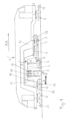
- the tamping machine 1 for tamping sleepers of a track 2 comprises a machine frame 14 which can be moved on two rail carriages 9 and extends in the longitudinal direction of the tamping machine, and a satellite 3 which is arranged between the rail carriages 9 and can be moved on the track 2 via a carriage 10, which is connected to the machine frame 14 via a satellite longitudinal guide 18 and which has a tamping unit 5 which is height-adjustable with respect to the satellite 3 and a track lifting and straightening unit 7 between the carriage 10 and the satellite longitudinal guide 18.
- the satellite 3 is connected directly to the machine frame 14 via a linear drive 4 with position detection, wherein the linear drive 4 accelerates and decelerates the satellite 3 within a provided displacement range A between the rail carriages 9 in such a way that a predetermined travel dimension is maintained.
- the longitudinally displaceable satellite 3 rests on the chassis 10.
- the satellite 3 is guided by satellite longitudinal guides 18 in the main frame 14 in the manner of a wheelbarrow, with one end having a running gear, at the other end it is guided longitudinally by guide arms.
- the machine 1 with the tamping cabin 15 can be moved on the track 2 via bogies 9, 10.
- the machine has a track measuring system 6, 11, 12 which is used to control the lifting and straightening unit 7, which is integrated in the satellite 3.
- On the satellite 3 there is a tamping unit 5 which can be lowered and raised and which can be rotated about the vertical axis by the angle ⁇ via a turntable 19 and can also be moved transversely via a displacement device 20 which is transverse to the working direction.
- the lifting and straightening unit can be moved in the longitudinal direction of the track via a linear drive 8 which is connected to the satellite frame 13.
- At least one lifting cylinder H and at least one straightening cylinder R are assigned to the track lifting and straightening unit
- the machine works in the working direction AR.
- the satellite 3 can be moved relative to the main frame 14 by the displacement range A within which the work-dependent (straightening and/or tamping, track bed quality) travel dimension lies.
- the satellite 3 is guided in or under the machine frame 14 via the linear drive 4, which has a particularly integrated distance measuring system, accelerated forwards in the direction of travel and braked again in time to precisely reach the required advance distance.
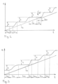
- the diagram Fig.2 shows the path s plotted vertically and the time axis t horizontally.
- the continuous constant advance speed v M of the main engine 1 is given by the straight line.
- the path-time curve of the satellite 3 is shown.
- T st corresponds to the tamping time
- t T is the dead time of the drive
- t F the advance time.
- an abnormal extension of the tamping time t st ' occurs. Since the advance path of the satellite t is exhausted, the main engine must stop for the time t Mst and can only resume its journey after the advance of the satellite 3.
- the diagram Fig.3 shows the path s plotted vertically and the time axis t horizontally.
- the continuous constant forward speed v M of the main engine 1 is given by the straight line.
- T st1 is the tamping time of the 1st tamping and t F1 the corresponding advance time. Since the linear drive according to the invention has no dead times t T , the time t F available for advance is longer at a comparable working speed v M.
- the starting and braking accelerations of the satellite 3 can be carried out more gently.
- the 2nd tamping for example, requires a longer time t st2 .
- the advance time t F2 is reduced accordingly, the starting and braking accelerations are automatically adjusted and become longer.
- the 3rd tamping requires t st3 with the starting and braking acceleration set accordingly, the advance time is t F3 etc. In this way, the tamping machine 1 can work at a constant speed even though the tamping times vary.
Landscapes
- Engineering & Computer Science (AREA)
- Architecture (AREA)
- Civil Engineering (AREA)
- Structural Engineering (AREA)
- Machines For Laying And Maintaining Railways (AREA)
Claims (7)
- Machine de bourrage (1) pour le bourrage de traverses d'une voie ferrée (2), comprenant un bâti de machine (14) qui s'étend dans le sens longitudinal de la machine de bourrage et qui peut être déplacé sur deux bogies pour rail (9), et un satellite (3) qui est disposé entre les bogies pour rail (9), qui peut être déplacé sur la voie ferrée (2) par un bogie (10), qui est relié de manière guidée au bâti de machine (14) par l'intermédiaire d'un guide longitudinal de satellite (18) et qui présente, entre le bogie (10) et le guide longitudinal de satellite (18), un ensemble de bourrage (5) réglable en hauteur par rapport au satellite (3) ainsi qu'un ensemble de levage et d'alignement de voie ferrée (7), dans laquelle le satellite (3) est relié directement au bâti de machine (14) par l'intermédiaire d'un entraînement linéaire (4), dans laquelle l'entraînement linéaire (4), comprenant deux vérins hydrauliques (4), accélère et freine le satellite (3) à l'intérieur d'une région de mouvement (A) prévue entre les bogies pour rail (9), de telle sorte qu'un degré de déplacement prédéfini soit respecté, caractérisé en ce que l'entraînement linéaire (4) présente une capacité de détection de position et en ce que, parmi les deux vérins hydrauliques (4), l'un pousse le satellite (3) en cas de repositionnement entre les bogies pour rail (9) et l'autre le tire, c'est-à-dire le freine.
- Machine de bourrage selon la revendication 1, caractérisée en ce que l'entraînement linéaire (4) est un vérin homocinétique présentant une capacité de détection de position.
- Machine de bourrage selon la revendication 1 ou 2, caractérisée par un circuit de régulation qui impose des accélérations de démarrage et de freinage du satellite (3) en fonction d'une vitesse de déplacement de la machine de bourrage, en particulier constante, par l'intermédiaire de l'entraînement linéaire (4), afin d'atteindre le degré de déplacement autorisé prédéfini.
- Machine de bourrage selon l'une quelconque des revendications 1 à 3, caractérisée par un circuit de régulation qui prédéfinit des accélérations de démarrage et de freinage du satellite (3) en fonction d'une vitesse de déplacement, en particulier constante, de la machine de bourrage pour différents temps de bourrage (tFi) par l'intermédiaire de l'entraînement linéaire (4), afin d'atteindre le degré de déplacement autorisé prédéfini.
- Machine de bourrage selon l'une quelconque des revendications 1 à 4, caractérisée en ce qu'un mécanisme de déplacement (16) est prévu sur le bogie (10) du satellite (3) en plus de l'entraînement linéaire (4).
- Machine de bourrage selon l'une quelconque des revendications 1 à 5, caractérisée en ce qu'un frein (17) est prévu sur le bogie (10) du satellite (3) en plus de l'entraînement linéaire (4).
- Machine de bourrage selon l'une quelconque des revendications 1 à 6, caractérisée en ce que le vérin hydraulique arrière (4) est un vérin de poussée qui fait avancer le satellite (3) dans la direction de travail, et en ce que le vérin hydraulique avant (4) est un vérin de freinage qui freine le satellite au niveau de la position à atteindre.
Applications Claiming Priority (2)
| Application Number | Priority Date | Filing Date | Title |
|---|---|---|---|
| ATA50686/2020A AT524100B1 (de) | 2020-08-14 | 2020-08-14 | Stopfmaschine zum Unterstopfen von Schwellen eines Gleises |
| PCT/AT2021/060279 WO2022032319A1 (fr) | 2020-08-14 | 2021-08-10 | Machine de bourrage pour le bourrage de traverses d'une voie ferrée |
Publications (3)
| Publication Number | Publication Date |
|---|---|
| EP4196638A1 EP4196638A1 (fr) | 2023-06-21 |
| EP4196638C0 EP4196638C0 (fr) | 2024-07-24 |
| EP4196638B1 true EP4196638B1 (fr) | 2024-07-24 |
Family
ID=77358027
Family Applications (1)
| Application Number | Title | Priority Date | Filing Date |
|---|---|---|---|
| EP21755353.6A Active EP4196638B1 (fr) | 2020-08-14 | 2021-08-10 | Machine de bourrage pour le bourrage de traverses d'une voie ferrée |
Country Status (5)
| Country | Link |
|---|---|
| EP (1) | EP4196638B1 (fr) |
| JP (1) | JP7604624B2 (fr) |
| CN (1) | CN116018440A (fr) |
| AT (1) | AT524100B1 (fr) |
| WO (1) | WO2022032319A1 (fr) |
Family Cites Families (10)
| Publication number | Priority date | Publication date | Assignee | Title |
|---|---|---|---|---|
| AT380279B (de) * | 1983-08-19 | 1986-05-12 | Plasser Bahnbaumasch Franz | Kontinuierlich (non-stop) verfahrbare gleisstopf-nivellier- und richtmaschine |
| AT379835B (de) * | 1983-08-19 | 1986-03-10 | Plasser Bahnbaumasch Franz | Kontinuierlich (non stop) verfahrbare gleisstopf -nivellier- und richtmaschine |
| AT383838B (de) * | 1984-06-01 | 1987-08-25 | Plasser Bahnbaumasch Franz | Kontinuierlich verfahrbare gleisstopf-nivellier- und richtmaschine |
| AT401943B (de) | 1992-08-21 | 1996-12-27 | Plasser Bahnbaumasch Franz | Kontinuierlich verfahrbare gleisstopfmaschine |
| EP0731217B1 (fr) * | 1995-03-07 | 2000-01-12 | Franz Plasser Bahnbaumaschinen-Industriegesellschaft m.b.H. | Machine à bourrage, assemblage et procédé de bourrage d'une voie ferrée |
| AT5705U3 (de) | 2002-07-04 | 2003-06-25 | Plasser Bahnbaumasch Franz | Stopfmaschine mit einem maschinen- und einem aggregatrahmen |
| AT5768U3 (de) | 2002-07-29 | 2003-09-25 | Plasser Bahnbaumasch Franz | Stopfmaschine |
| CN103588087B (zh) * | 2013-11-25 | 2015-04-08 | 华电重工股份有限公司 | 弧形轨道多缸协同步履推进方法 |
| AT515801B1 (de) * | 2014-09-16 | 2015-12-15 | System 7 Railsupport Gmbh | Verfahren zum Verdichten des Schotterbettes eines Gleises |
| AT16251U1 (de) * | 2018-01-22 | 2019-05-15 | Hp3 Real Gmbh | Stopfaggregat für eine Gleisstopfmaschine |
-
2020
- 2020-08-14 AT ATA50686/2020A patent/AT524100B1/de not_active IP Right Cessation
-
2021
- 2021-08-10 JP JP2023510327A patent/JP7604624B2/ja active Active
- 2021-08-10 WO PCT/AT2021/060279 patent/WO2022032319A1/fr not_active Ceased
- 2021-08-10 CN CN202180056075.XA patent/CN116018440A/zh active Pending
- 2021-08-10 EP EP21755353.6A patent/EP4196638B1/fr active Active
Also Published As
| Publication number | Publication date |
|---|---|
| EP4196638C0 (fr) | 2024-07-24 |
| WO2022032319A1 (fr) | 2022-02-17 |
| AT524100A1 (de) | 2022-02-15 |
| CN116018440A (zh) | 2023-04-25 |
| JP2023537140A (ja) | 2023-08-30 |
| AT524100B1 (de) | 2025-02-15 |
| EP4196638A1 (fr) | 2023-06-21 |
| JP7604624B2 (ja) | 2024-12-23 |
Similar Documents
| Publication | Publication Date | Title |
|---|---|---|
| DE2114281C3 (de) | Fahrbare Gleisstopfmaschine, insbesondere Gleisnivellier-Richt-Stopfmaschine | |
| CH626415A5 (fr) | ||
| EP0360950B1 (fr) | Machine de bourrage, de nivellement ou de dressage de voie ferrée, déplaçable de façon continue (sans arrêt) | |
| DD211376A5 (de) | Fahrbare gleisstopfmaschine mit zwei miteinander gelenkig verbundenen fahrgestell-rahmen | |
| DE3886418T2 (de) | Schienenschleifvorrichtung. | |
| EP0342306B1 (fr) | Machine pour ripage latéral d'une voie constituée de rails et de traverses transversales | |
| DE3015227C2 (de) | Gleisverfahrbare Maschine zum Abtragen von Unregelmäßigkeiten an der Schienenkopfoberseite eines verlegten Gleises | |
| DE3122898A1 (de) | Fahrbare gleisbaumaschine mit schienenfahrwerken und schrittweiser arbeitsvorfahrt | |
| DE3409854C2 (fr) | ||
| EP1387003B1 (fr) | Bourreuse | |
| EP4196638B1 (fr) | Machine de bourrage pour le bourrage de traverses d'une voie ferrée | |
| EP4214363A1 (fr) | Procédé et machine de bourrage de voie pour le bourrage d'une voie | |
| AT390459B (de) | Verfahren und gleisfahrbare weichen-nivellier-, stopf- und richt-maschinenanordnung zur durcharbeitung in weichenbereichen | |
| DE3425637A1 (de) | Kontinuierlich verfahrbare gleisstopf-nivellier- und richtmaschine | |
| DE3448190C2 (fr) | ||
| DE3409849C2 (fr) | ||
| EP4008838B1 (fr) | Machine de bourrage permettant de bourrer les traverses d'une voie ferrée | |
| EP4453314B1 (fr) | Machine de bourrage pour le bourrage de traverses d'une voie ferrée | |
| DE1534080B2 (de) | Verfahren zum unterstopfen der querschwellen eines gleises | |
| DE1709525A1 (de) | Gleisnivellier- und stopfmaschine | |
| EP4709934A1 (fr) | Machine de bourrage, système et procédé de bourrage d'une voie | |
| DE1534078C3 (de) | Fahrbare Gleisstopf-, Nivellier- und Richtmaschine | |
| DE1125464B (de) | Vorrichtung zum seitlichen Verschieben eines Gleises |
Legal Events
| Date | Code | Title | Description |
|---|---|---|---|
| STAA | Information on the status of an ep patent application or granted ep patent |
Free format text: STATUS: UNKNOWN |
|
| STAA | Information on the status of an ep patent application or granted ep patent |
Free format text: STATUS: THE INTERNATIONAL PUBLICATION HAS BEEN MADE |
|
| PUAI | Public reference made under article 153(3) epc to a published international application that has entered the european phase |
Free format text: ORIGINAL CODE: 0009012 |
|
| STAA | Information on the status of an ep patent application or granted ep patent |
Free format text: STATUS: REQUEST FOR EXAMINATION WAS MADE |
|
| 17P | Request for examination filed |
Effective date: 20230105 |
|
| AK | Designated contracting states |
Kind code of ref document: A1 Designated state(s): AL AT BE BG CH CY CZ DE DK EE ES FI FR GB GR HR HU IE IS IT LI LT LU LV MC MK MT NL NO PL PT RO RS SE SI SK SM TR |
|
| DAV | Request for validation of the european patent (deleted) | ||
| DAX | Request for extension of the european patent (deleted) | ||
| GRAP | Despatch of communication of intention to grant a patent |
Free format text: ORIGINAL CODE: EPIDOSNIGR1 |
|
| STAA | Information on the status of an ep patent application or granted ep patent |
Free format text: STATUS: GRANT OF PATENT IS INTENDED |
|
| INTG | Intention to grant announced |
Effective date: 20240227 |
|
| GRAS | Grant fee paid |
Free format text: ORIGINAL CODE: EPIDOSNIGR3 |
|
| GRAA | (expected) grant |
Free format text: ORIGINAL CODE: 0009210 |
|
| STAA | Information on the status of an ep patent application or granted ep patent |
Free format text: STATUS: THE PATENT HAS BEEN GRANTED |
|
| AK | Designated contracting states |
Kind code of ref document: B1 Designated state(s): AL AT BE BG CH CY CZ DE DK EE ES FI FR GB GR HR HU IE IS IT LI LT LU LV MC MK MT NL NO PL PT RO RS SE SI SK SM TR |
|
| REG | Reference to a national code |
Ref country code: GB Ref legal event code: FG4D Free format text: NOT ENGLISH |
|
| REG | Reference to a national code |
Ref country code: CH Ref legal event code: EP |
|
| REG | Reference to a national code |
Ref country code: IE Ref legal event code: FG4D Free format text: LANGUAGE OF EP DOCUMENT: GERMAN Ref country code: DE Ref legal event code: R096 Ref document number: 502021004503 Country of ref document: DE |
|
| U01 | Request for unitary effect filed |
Effective date: 20240822 |
|
| U07 | Unitary effect registered |
Designated state(s): AT BE BG DE DK EE FI FR IT LT LU LV MT NL PT RO SE SI Effective date: 20240902 |
|
| U20 | Renewal fee for the european patent with unitary effect paid |
Year of fee payment: 4 Effective date: 20240830 |
|
| PG25 | Lapsed in a contracting state [announced via postgrant information from national office to epo] |
Ref country code: NO Free format text: LAPSE BECAUSE OF FAILURE TO SUBMIT A TRANSLATION OF THE DESCRIPTION OR TO PAY THE FEE WITHIN THE PRESCRIBED TIME-LIMIT Effective date: 20241024 |
|
| PG25 | Lapsed in a contracting state [announced via postgrant information from national office to epo] |
Ref country code: PL Free format text: LAPSE BECAUSE OF FAILURE TO SUBMIT A TRANSLATION OF THE DESCRIPTION OR TO PAY THE FEE WITHIN THE PRESCRIBED TIME-LIMIT Effective date: 20240724 Ref country code: GR Free format text: LAPSE BECAUSE OF FAILURE TO SUBMIT A TRANSLATION OF THE DESCRIPTION OR TO PAY THE FEE WITHIN THE PRESCRIBED TIME-LIMIT Effective date: 20241025 |
|
| PG25 | Lapsed in a contracting state [announced via postgrant information from national office to epo] |
Ref country code: IS Free format text: LAPSE BECAUSE OF FAILURE TO SUBMIT A TRANSLATION OF THE DESCRIPTION OR TO PAY THE FEE WITHIN THE PRESCRIBED TIME-LIMIT Effective date: 20241124 |
|
| PG25 | Lapsed in a contracting state [announced via postgrant information from national office to epo] |
Ref country code: HR Free format text: LAPSE BECAUSE OF FAILURE TO SUBMIT A TRANSLATION OF THE DESCRIPTION OR TO PAY THE FEE WITHIN THE PRESCRIBED TIME-LIMIT Effective date: 20240724 |
|
| PG25 | Lapsed in a contracting state [announced via postgrant information from national office to epo] |
Ref country code: RS Free format text: LAPSE BECAUSE OF FAILURE TO SUBMIT A TRANSLATION OF THE DESCRIPTION OR TO PAY THE FEE WITHIN THE PRESCRIBED TIME-LIMIT Effective date: 20241024 Ref country code: ES Free format text: LAPSE BECAUSE OF FAILURE TO SUBMIT A TRANSLATION OF THE DESCRIPTION OR TO PAY THE FEE WITHIN THE PRESCRIBED TIME-LIMIT Effective date: 20240724 |
|
| PG25 | Lapsed in a contracting state [announced via postgrant information from national office to epo] |
Ref country code: RS Free format text: LAPSE BECAUSE OF FAILURE TO SUBMIT A TRANSLATION OF THE DESCRIPTION OR TO PAY THE FEE WITHIN THE PRESCRIBED TIME-LIMIT Effective date: 20241024 Ref country code: PL Free format text: LAPSE BECAUSE OF FAILURE TO SUBMIT A TRANSLATION OF THE DESCRIPTION OR TO PAY THE FEE WITHIN THE PRESCRIBED TIME-LIMIT Effective date: 20240724 Ref country code: NO Free format text: LAPSE BECAUSE OF FAILURE TO SUBMIT A TRANSLATION OF THE DESCRIPTION OR TO PAY THE FEE WITHIN THE PRESCRIBED TIME-LIMIT Effective date: 20241024 Ref country code: IS Free format text: LAPSE BECAUSE OF FAILURE TO SUBMIT A TRANSLATION OF THE DESCRIPTION OR TO PAY THE FEE WITHIN THE PRESCRIBED TIME-LIMIT Effective date: 20241124 Ref country code: HR Free format text: LAPSE BECAUSE OF FAILURE TO SUBMIT A TRANSLATION OF THE DESCRIPTION OR TO PAY THE FEE WITHIN THE PRESCRIBED TIME-LIMIT Effective date: 20240724 Ref country code: GR Free format text: LAPSE BECAUSE OF FAILURE TO SUBMIT A TRANSLATION OF THE DESCRIPTION OR TO PAY THE FEE WITHIN THE PRESCRIBED TIME-LIMIT Effective date: 20241025 Ref country code: ES Free format text: LAPSE BECAUSE OF FAILURE TO SUBMIT A TRANSLATION OF THE DESCRIPTION OR TO PAY THE FEE WITHIN THE PRESCRIBED TIME-LIMIT Effective date: 20240724 |
|
| REG | Reference to a national code |
Ref country code: CH Ref legal event code: PL |
|
| PG25 | Lapsed in a contracting state [announced via postgrant information from national office to epo] |
Ref country code: SM Free format text: LAPSE BECAUSE OF FAILURE TO SUBMIT A TRANSLATION OF THE DESCRIPTION OR TO PAY THE FEE WITHIN THE PRESCRIBED TIME-LIMIT Effective date: 20240724 |
|
| PG25 | Lapsed in a contracting state [announced via postgrant information from national office to epo] |
Ref country code: MC Free format text: LAPSE BECAUSE OF FAILURE TO SUBMIT A TRANSLATION OF THE DESCRIPTION OR TO PAY THE FEE WITHIN THE PRESCRIBED TIME-LIMIT Effective date: 20240724 Ref country code: CH Free format text: LAPSE BECAUSE OF NON-PAYMENT OF DUE FEES Effective date: 20240831 |
|
| PG25 | Lapsed in a contracting state [announced via postgrant information from national office to epo] |
Ref country code: CZ Free format text: LAPSE BECAUSE OF FAILURE TO SUBMIT A TRANSLATION OF THE DESCRIPTION OR TO PAY THE FEE WITHIN THE PRESCRIBED TIME-LIMIT Effective date: 20240724 |
|
| PG25 | Lapsed in a contracting state [announced via postgrant information from national office to epo] |
Ref country code: SK Free format text: LAPSE BECAUSE OF FAILURE TO SUBMIT A TRANSLATION OF THE DESCRIPTION OR TO PAY THE FEE WITHIN THE PRESCRIBED TIME-LIMIT Effective date: 20240724 |
|
| PLBE | No opposition filed within time limit |
Free format text: ORIGINAL CODE: 0009261 |
|
| STAA | Information on the status of an ep patent application or granted ep patent |
Free format text: STATUS: NO OPPOSITION FILED WITHIN TIME LIMIT |
|
| 26N | No opposition filed |
Effective date: 20250425 |
|
| PG25 | Lapsed in a contracting state [announced via postgrant information from national office to epo] |
Ref country code: IE Free format text: LAPSE BECAUSE OF NON-PAYMENT OF DUE FEES Effective date: 20240810 |
|
| U20 | Renewal fee for the european patent with unitary effect paid |
Year of fee payment: 5 Effective date: 20250825 |
|
| PG25 | Lapsed in a contracting state [announced via postgrant information from national office to epo] |
Ref country code: CY Free format text: LAPSE BECAUSE OF FAILURE TO SUBMIT A TRANSLATION OF THE DESCRIPTION OR TO PAY THE FEE WITHIN THE PRESCRIBED TIME-LIMIT; INVALID AB INITIO Effective date: 20210810 |
|
| PG25 | Lapsed in a contracting state [announced via postgrant information from national office to epo] |
Ref country code: HU Free format text: LAPSE BECAUSE OF FAILURE TO SUBMIT A TRANSLATION OF THE DESCRIPTION OR TO PAY THE FEE WITHIN THE PRESCRIBED TIME-LIMIT; INVALID AB INITIO Effective date: 20210810 |