EP4196665B1 - Aube de turbine à gaz et méthode - Google Patents
Aube de turbine à gaz et méthode Download PDFInfo
- Publication number
- EP4196665B1 EP4196665B1 EP21835447.0A EP21835447A EP4196665B1 EP 4196665 B1 EP4196665 B1 EP 4196665B1 EP 21835447 A EP21835447 A EP 21835447A EP 4196665 B1 EP4196665 B1 EP 4196665B1
- Authority
- EP
- European Patent Office
- Prior art keywords
- platform
- gas turbine
- plate
- turbine blade
- blade
- Prior art date
- Legal status (The legal status is an assumption and is not a legal conclusion. Google has not performed a legal analysis and makes no representation as to the accuracy of the status listed.)
- Active
Links
Images



Classifications
-
- F—MECHANICAL ENGINEERING; LIGHTING; HEATING; WEAPONS; BLASTING
- F01—MACHINES OR ENGINES IN GENERAL; ENGINE PLANTS IN GENERAL; STEAM ENGINES
- F01D—NON-POSITIVE DISPLACEMENT MACHINES OR ENGINES, e.g. STEAM TURBINES
- F01D5/00—Blades; Blade-carrying members; Heating, heat-insulating, cooling or antivibration means on the blades or the members
- F01D5/12—Blades
- F01D5/14—Form or construction
- F01D5/18—Hollow blades, i.e. blades with cooling or heating channels or cavities; Heating, heat-insulating or cooling means on blades
- F01D5/187—Convection cooling
-
- F—MECHANICAL ENGINEERING; LIGHTING; HEATING; WEAPONS; BLASTING
- F01—MACHINES OR ENGINES IN GENERAL; ENGINE PLANTS IN GENERAL; STEAM ENGINES
- F01D—NON-POSITIVE DISPLACEMENT MACHINES OR ENGINES, e.g. STEAM TURBINES
- F01D5/00—Blades; Blade-carrying members; Heating, heat-insulating, cooling or antivibration means on the blades or the members
- F01D5/12—Blades
- F01D5/14—Form or construction
- F01D5/18—Hollow blades, i.e. blades with cooling or heating channels or cavities; Heating, heat-insulating or cooling means on blades
- F01D5/186—Film cooling
-
- F—MECHANICAL ENGINEERING; LIGHTING; HEATING; WEAPONS; BLASTING
- F05—INDEXING SCHEMES RELATING TO ENGINES OR PUMPS IN VARIOUS SUBCLASSES OF CLASSES F01-F04
- F05D—INDEXING SCHEME FOR ASPECTS RELATING TO NON-POSITIVE-DISPLACEMENT MACHINES OR ENGINES, GAS-TURBINES OR JET-PROPULSION PLANTS
- F05D2220/00—Application
- F05D2220/30—Application in turbines
- F05D2220/32—Application in turbines in gas turbines
-
- F—MECHANICAL ENGINEERING; LIGHTING; HEATING; WEAPONS; BLASTING
- F05—INDEXING SCHEMES RELATING TO ENGINES OR PUMPS IN VARIOUS SUBCLASSES OF CLASSES F01-F04
- F05D—INDEXING SCHEME FOR ASPECTS RELATING TO NON-POSITIVE-DISPLACEMENT MACHINES OR ENGINES, GAS-TURBINES OR JET-PROPULSION PLANTS
- F05D2230/00—Manufacture
- F05D2230/80—Repairing, retrofitting or upgrading methods
-
- F—MECHANICAL ENGINEERING; LIGHTING; HEATING; WEAPONS; BLASTING
- F05—INDEXING SCHEMES RELATING TO ENGINES OR PUMPS IN VARIOUS SUBCLASSES OF CLASSES F01-F04
- F05D—INDEXING SCHEME FOR ASPECTS RELATING TO NON-POSITIVE-DISPLACEMENT MACHINES OR ENGINES, GAS-TURBINES OR JET-PROPULSION PLANTS
- F05D2240/00—Components
- F05D2240/20—Rotors
- F05D2240/30—Characteristics of rotor blades, i.e. of any element transforming dynamic fluid energy to or from rotational energy and being attached to a rotor
-
- F—MECHANICAL ENGINEERING; LIGHTING; HEATING; WEAPONS; BLASTING
- F05—INDEXING SCHEMES RELATING TO ENGINES OR PUMPS IN VARIOUS SUBCLASSES OF CLASSES F01-F04
- F05D—INDEXING SCHEME FOR ASPECTS RELATING TO NON-POSITIVE-DISPLACEMENT MACHINES OR ENGINES, GAS-TURBINES OR JET-PROPULSION PLANTS
- F05D2240/00—Components
- F05D2240/80—Platforms for stationary or moving blades
- F05D2240/81—Cooled platforms
-
- F—MECHANICAL ENGINEERING; LIGHTING; HEATING; WEAPONS; BLASTING
- F05—INDEXING SCHEMES RELATING TO ENGINES OR PUMPS IN VARIOUS SUBCLASSES OF CLASSES F01-F04
- F05D—INDEXING SCHEME FOR ASPECTS RELATING TO NON-POSITIVE-DISPLACEMENT MACHINES OR ENGINES, GAS-TURBINES OR JET-PROPULSION PLANTS
- F05D2260/00—Function
- F05D2260/20—Heat transfer, e.g. cooling
- F05D2260/201—Heat transfer, e.g. cooling by impingement of a fluid
-
- F—MECHANICAL ENGINEERING; LIGHTING; HEATING; WEAPONS; BLASTING
- F05—INDEXING SCHEMES RELATING TO ENGINES OR PUMPS IN VARIOUS SUBCLASSES OF CLASSES F01-F04
- F05D—INDEXING SCHEME FOR ASPECTS RELATING TO NON-POSITIVE-DISPLACEMENT MACHINES OR ENGINES, GAS-TURBINES OR JET-PROPULSION PLANTS
- F05D2260/00—Function
- F05D2260/20—Heat transfer, e.g. cooling
- F05D2260/202—Heat transfer, e.g. cooling by film cooling
Definitions
- Blades and vanes in the turbine section of the gas turbine engine are among these internal components.
- the high temperatures often cause damage to the components, so the components are designed to utilize various cooling schemes to cool the surfaces of the blades and vanes that are exposed to the hot combustion gases.
- blades and vanes are often constructed of high temperature superalloys coated with barrier coatings that can withstand the high temperatures.
- the superalloy components often include cooling passages terminating on the component outer surface for passage of coolant fluid to cool the surfaces exposed to the hot combustion gases.
- US2012082550 discloses a gas turbine blade according to the state of the art.
- the invention concerns a gas turbine blade in accordance with appended claim 1 and a method according to appended claim 12. Further embodiments are defined in the dependent claims.
- phrases "associated with” and “associated therewith,” as well as derivatives thereof, may mean to include, be included within, interconnect with, contain, be contained within, connect to or with, couple to or with, be communicable with, cooperate with, interleave, juxtapose, be proximate to, be bound to or with, have, have a property of, or the like.
- any features, methods, steps, components, etc. described with regard to one embodiment are equally applicable to other embodiments absent a specific statement to the contrary.
- first, second, third and so forth may be used herein to refer to various elements, information, functions, or acts, these elements, information, functions, or acts should not be limited by these terms. Rather these numeral adjectives are used to distinguish different elements, information, functions or acts from each other. For example, a first element, information, function, or act could be termed a second element, information, function, or act, and, similarly, a second element, information, function, or act could be termed a first element, information, function, or act, without departing from the scope of the present disclosure.
- adjacent to may mean: that an element is relatively near to but not in contact with a further element; or that the element is in contact with the further portion, unless the context clearly indicates otherwise.
- phrase “based on” is intended to mean “based, at least in part, on” unless explicitly stated otherwise. Terms “about” or “substantially” or like terms are intended to cover variations in a value that are within normal industry manufacturing tolerances for that dimension. If no industry standard is available, a variation of twenty percent would fall within the meaning of these terms unless otherwise stated.
- FIG. 1 illustrates an example of a gas turbine engine 100 including a compressor section 104, a combustion section 102, and a turbine section 106 arranged along a central axis 122.
- the compressor section 104 includes a plurality of compressor stages 108 with each compressor stage 108 including a set of turbine blades 126 and a set of stationary vanes 124 or adjustable guide vanes.
- a rotor 128 supports the turbine blades 126 for rotation about the central axis 122 during operation.
- a single one-piece rotor 128 extends the length of the gas turbine engine 100 and is supported for rotation by a bearing at either end.
- the rotor 128 is assembled from several separate spools that are attached to one another or may include multiple disk sections that are attached via a bolt or plurality of bolts.
- the compressor section 104 is in fluid communication with an inlet section 116 to allow the gas turbine engine 100 to draw atmospheric air into the compressor section 104. During operation of the gas turbine engine 100, the compressor section 104 draws in atmospheric air and compresses that air for delivery to the combustion section 102.
- the illustrated compressor section 104 is an example of one compressor section 104 with other arrangements and designs being possible.
- the combustion section 102 includes a plurality of separate combustors 112 that each operate to mix a flow of fuel with the compressed air from the compressor section 104 and to combust that air-fuel mixture to produce a flow of high temperature, high pressure combustion gases or exhaust gas 118.
- combustors 112 that each operate to mix a flow of fuel with the compressed air from the compressor section 104 and to combust that air-fuel mixture to produce a flow of high temperature, high pressure combustion gases or exhaust gas 118.
- many other arrangements of the combustion section 102 are possible.
- the turbine section 106 includes a plurality of turbine stages 110 with each turbine stage 110 including a number of rotating turbine blades 126 and a number of stationary blades or vanes.
- the turbine stages 110 are arranged to receive the exhaust gas 118 from the combustion section 102 at a turbine inlet 114 and expand that gas to convert thermal and pressure energy into rotating or mechanical work.
- the turbine section 106 is connected to the compressor section 104 to drive the compressor section 104.
- the turbine section 106 is also connected to a generator, pump, or other device to be driven.
- the compressor section 104 other designs and arrangements of the turbine section 106 are possible.
- a control system 120 is coupled to the gas turbine engine 100 and operates to monitor various operating parameters and to control various operations of the gas turbine engine 100.
- the control system 120 is typically micro-processor based and includes memory devices and data storage devices for collecting, analyzing, and storing data.
- the control system 120 provides output data to various devices including monitors, printers, indicators, and the like that allow users to interface with the control system 120 to provide inputs or adjustments.
- a user may input a power output set point and the control system 120 may adjust the various control inputs to achieve that power output in an efficient manner.
- the control system 120 can control various operating parameters including, but not limited to variable inlet guide vane positions, fuel flow rates and pressures, engine speed, valve positions, generator load, and generator excitation. Of course, other applications may have fewer or more controllable devices.
- the control system 120 also monitors various parameters to assure that the gas turbine engine 100 is operating properly. Some parameters that are monitored may include inlet air temperature, compressor outlet temperature and pressure, combustor outlet temperature, fuel flow rate, generator power output, bearing temperature, and the like. Many of these measurements are displayed for the user and are logged for later review should such a review be necessary.
- FIG. 2 illustrates a perspective view of a turbine blade 126 as may be found in a gas turbine engine 100.
- the turbine blade 126 includes an airfoil 202, a platform 204, and a root 206.
- the root 206 may be connected to a rotor 128 of the gas turbine engine 100.
- a platform 204 is formed at a radially outward portion of the root 206 and is in between the root 206 and the airfoil 202.
- the airfoil 202 is attached to the platform 204 and extends in a radial direction outwards from the platform 204 to a tip 218.
- the airfoil 202 includes an outer surface having a pressure side 214 and a suction side 216.
- the pressure side 214 and suction side meet at an upstream leading edge 210 and a downstream trailing edge 208.
- the terms 'leading' and 'trailing' are used in relation to a fluid flow of the working flow of the gas turbine engine 100.
- a platform impingement plate 212 is shown in FIG. 2 residing on the side of the platform 204 facing the root 206 and opposite the airfoil 202.
- FIG. 3 shows a further view of the platform impingement plate 212.
- the platform impingement plate 212 attaches to a first surface of the platform facing the root 206 and on the surface opposite the surface of the platform from which the airfoil 202 extends. Additionally, the platform impingement plate 212 resides on the pressure side 214 of the turbine blade 126.
- FIG. 4 shows a perspective top view of the platform impingement plate 212.
- the platform impingement plate 212 includes a circumferential edge 404 that contacts and is attached to the first surface of the platform 204.
- the circumferential edge 404 is in continuous contact with the first surface of the platform 204.
- the edge 404 surrounds a cavity 406, the cavity 406 defined by a plate surface 410 and the surrounding edge 404.
- the plate surface 410 may include at least one impingement hole 402. In an embodiment, the plate surface 410 includes more than one impingement hole 402.
- the impingement holes 402 enable a fluid flow to cool the first surface of the platform.
- the platform impingement plate 212 includes a flat member 408 having a face attached to the plate surface 410.
- the flat member 408 includes at least one end portion, the end portion extends beyond the plate surface 410 and includes a curved end.
- the curved end fits into a groove in the platform 204.
- An embodiment shown in FIG. 4 includes a flat member 408 having two end portions, each end portion including a curved end.
- Each of the curved ends fit into a corresponding groove in the platform 204 so that the platform impingement plate 212 may be attached to the platform 204.
- the curved ends are slightly larger than the grooves so that they deform slightly when installed to hold the platform impingement plate 212 in place.
- the platform impingement plate 212 is additively manufactured.
- Additive Manufacturing enables the manufacturing of components that are difficult to manufacture using conventional manufacturing techniques such as the curved ends of the flat member 408.
- FIG. 5 shows a perspective view of turbine blade 126 viewed so that a bottom of the root 206 may be seen.
- a bottom face of the root 206 includes at least one root cavity 504.
- the root 206 includes three root cavities 504.
- an orifice plate 502 is shown having a plate that covers the opening into the root cavity 504.
- FIG. 6 shows a perspective view of the orifice plate 502 as shown in the root cavity 504 of root 206 in FIG. 5 .
- the orifice plate 502 includes a plate 602 having at least one orifice 606.
- the plate 602 includes an octagonal shape. Extending from a first surface of the plate 602 is at least one insertion plate 604.
- two insertion plates 604 extend from the first surface of the plate 602.
- the insertion plates 604 may be inserted into the root cavity 504 where they are fitted into the root cavity 504.
- the plate 602 may include at least one fin 608 extending from a second surface of the plate 602 opposite the first surface.
- FIG. 7 illustrates the platform 204 at the trailing edge 208.
- the platform 204 on the trailing edge side extends to the end of the trailing edge 208 such that it may be shorter than a traditional turbine blade.
- the shorter platform 204 is easier to cool and to prevent oxidation and TBC damage.
- Turbine engine internal components such as the turbine blade 126 shown in FIG. 8 , often incorporate a thermal barrier coating (TBC) of metal-ceramic material that is applied directly to the external surface of the component substrate surface or over an intermediate metallic bond coat that was previously applied to the substrate surface.
- TBC thermal barrier coating
- the TBC provides an insulating layer over the component substrate, which reduces the substrate temperature.
- FIG. 8 includes a perspective view of turbine blade 126 having a thermal protection system 802 that may include a bond coat applied to the substrate.
- the thermal protection system 802 may also include a thermal barrier coating applied over the bond coat as a topcoat. In an alternate embodiment, the thermal barrier coating is applied directly to the metallic substrate.
- the thermal protection system 802 is applied to portions of the airfoil 202 and/or applied to the platform 204.
- the bond coat may be applied to the entire airfoil substrate including the tip 218, leading edge 210, trailing edge 208, suction side 216, and pressure side 214.
- the bond coat may be applied to the platform 204.
- Surfaces included for the bond coat application may include those denoted by A, B, C, and D.
- the bond coat comprises platinum aluminum alloy (PtAl).
- the topcoat may be applied by an Electron Beam Physical Vapor Deposited (EBPVD) process over the bond coat on the platform 204 and portions of the airfoil 202.
- EBPVD Electron Beam Physical Vapor Deposited
- the topcoat is applied to the tip 218, pressure side 214, suction side 216 and leading edge 210, but not on the trailing edge 208.
- the thermal protection system 802, PtAl bond coat and EBPVD topcoat has a better surface finish than air plasma sprayed (APS) coatings resulting in an efficiency advantage.
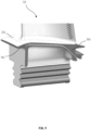
- FIG. 9 shows a partial perspective view of a turbine blade 126 having a sealing wire 902.
- the turbine blade 126 in FIG. 9 includes a platform 204 including a side surface 904 with a groove formed in the side surface 904.
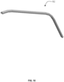
- the sealing wire 902, as shown in FIG. 10 includes a first curved portion and a second flat portion such that the sealing wire 902 includes a D-shaped cross section.
- the sealing wire 902 is oriented such that the second flat portion faces toward the inner diameter of the gas turbine engine.
- Utilizing a sealing wire instead of sealing strip incurs less machining to install within the platform 204 and includes a dynamic damping advantage.
- the sealing wire 902 is compressed between two adjacent turbine blades 126 and is resilient such that vibrations between the turbine blade 126 are reduced.
- FIG. 11 illustrates a turbine blade 126 having a platform 204 with a damping cavity 1102 on the trailing edge side of the platform 204.
- the damping cavity 1102 receives a leading edge portion 1106 of an adjacent guide vane 1104 of the next stage.
- the adjacent guide vane 1104 includes a T-shaped platform 1108 that reduces hot gas ingestion into the platform cavity.
Landscapes
- Engineering & Computer Science (AREA)
- Mechanical Engineering (AREA)
- General Engineering & Computer Science (AREA)
- Turbine Rotor Nozzle Sealing (AREA)
Claims (14)
- Aube de turbine à gaz (126), comprenant :une emplanture (206) destinée à être reliée à un rotor (128) d'un moteur à turbine à gaz ;une plate-forme (204) fixée à l'emplanture et définissant au moins une rainure ;une plaque d'incidence de plate-forme (212), comprenant :un bord circonférentiel (404) entourant une cavité (406), le bord étant positionné pour entrer en contact avec une première surface de la plaque-forme, une première surface de plaque et une seconde surface de plaque opposée à ladite première surface de plaque, ladite première surface de plaque étant positionnée pour former la cavité (406) entre la première surface et la première surface de plaque, etun profil aérodynamique (202) comprenant un substrat métallique s'étendant depuis une seconde surface de la plaque-forme opposée à la première surface jusqu'à un bout, le profil aérodynamique incluant un côté pression (214) et un côté aspiration (216), le côté pression et le côté aspiration se rejoignant au niveau d'un bord de fuite et d'un bord d'attaque,dans laquelle les première et seconde surfaces de plaque incluent au moins un trou d'incidence (402) à travers lequel un écoulement de fluide s'écoule pour refroidir la première surface de la plaque-forme, caractérisée en ce que l'aube comprend en outre un élément plat (408) ayant une face fixée à la seconde surface de plaque et au moins une partie d'extrémité, dans laquelle chaque partie d'extrémité s'étend au-delà des première et seconde surfaces de plaque et inclut une courbure de telle sorte que chaque partie d'extrémité courbée est insérée dans une rainure correspondante dans la plaque-forme.
- Aube de turbine à gaz de la revendication 1, dans laquelle la plaque d'incidence de plate-forme entre en contact avec la première surface sur le côté pression de l'aube de turbine.
- Aube de turbine à gaz de la revendication 1, dans laquelle la plaque d'incidence de plate-forme est fabriquée de façon additive.
- Aube de turbine à gaz de la revendication 1, dans laquelle l'emplanture définit une cavité (504),
et dans laquelle une plaque à orifice (502) inclut une plaque (602) incluant un orifice (606) et au moins une plaque d'insertion (604), la plaque d'insertion étant ajustée dans la cavité dans l'emplanture de manière telle que la plaque couvre la cavité. - Aube de turbine à gaz de la revendication 1, dans laquelle la plaque à orifice (502) est de forme octogonale.
- Aube de turbine à gaz de la revendication 1, dans laquelle le profil aérodynamique comprend en outre un système de protection thermique (802) déposé sur le substrat, le système de protection thermique inclut une couche liante appliquée sur le substrat métallique et un revêtement barrière thermique incluant une couche supérieure EBPVD appliquée par-dessus la couche liante sur une partie du profil aérodynamique.
- Aube de turbine à gaz de la revendication 6 dans laquelle la couche liante comprend PtAl.
- Aube de turbine à gaz de la revendication 6, dans laquelle la partie du profil aérodynamique inclut le côté aspiration, le côté pression, le bout, et le bord d'attaque.
- Aube de turbine à gaz de la revendication 6, dans laquelle la plaque-forme comprend en outre un système de protection thermique (802) déposé sur la seconde surface, le système de protection thermique incluant une couche liante appliquée sur la seconde surface et un revêtement barrière thermique incluant une couche supérieure EBPVD appliquée par-dessus la couche liante.
- Aube de turbine à gaz de la revendication 9, dans laquelle la couche liante comprend PtAl.
- Aube de turbine à gaz de la revendication 1, dans laquelle la plaque-forme s'étend jusqu'au bord de fuite sur le côté bord de fuite de la plaque-forme.
- Procédé d'entretien d'un moteur à turbine à gaz ayant l'aube selon une ou plusieurs des revendications 1 à 11, comprenant :
le montage de l'aube sur le rotor. - Procédé selon la revendication 12, dans lequel l'aube est montée de manière telle qu'une cavité d'amortissement (1102) sur un côté bord de fuite d'une plate-forme (204) de l'aube reçoit une partie de bord d'attaque (1106) d'une aube directrice adjacente (1104),
et dans lequel l'aube de turbine a une plate-forme en forme de T, moyennant quoi, durant le fonctionnement du moteur à turbine à gaz, l'interaction de la partie de bord d'attaque avec la cavité d'amortissement amortit la vibration. - Procédé selon la revendication 13, comprenant en outre :
le montage de l'aube de turbine (1104) sur un stator du moteur à turbine à gaz.
Applications Claiming Priority (3)
| Application Number | Priority Date | Filing Date | Title |
|---|---|---|---|
| US202062706535P | 2020-08-24 | 2020-08-24 | |
| US202063074786P | 2020-09-04 | 2020-09-04 | |
| PCT/US2021/046709 WO2022051101A2 (fr) | 2020-08-24 | 2021-08-19 | Aube de turbine à gaz |
Publications (3)
| Publication Number | Publication Date |
|---|---|
| EP4196665A2 EP4196665A2 (fr) | 2023-06-21 |
| EP4196665B1 true EP4196665B1 (fr) | 2025-06-11 |
| EP4196665C0 EP4196665C0 (fr) | 2025-06-11 |
Family
ID=79171351
Family Applications (1)
| Application Number | Title | Priority Date | Filing Date |
|---|---|---|---|
| EP21835447.0A Active EP4196665B1 (fr) | 2020-08-24 | 2021-08-19 | Aube de turbine à gaz et méthode |
Country Status (3)
| Country | Link |
|---|---|
| US (1) | US12044142B2 (fr) |
| EP (1) | EP4196665B1 (fr) |
| WO (1) | WO2022051101A2 (fr) |
Family Cites Families (5)
| Publication number | Priority date | Publication date | Assignee | Title |
|---|---|---|---|---|
| US7322797B2 (en) * | 2005-12-08 | 2008-01-29 | General Electric Company | Damper cooled turbine blade |
| US8684664B2 (en) * | 2010-09-30 | 2014-04-01 | General Electric Company | Apparatus and methods for cooling platform regions of turbine rotor blades |
| EP2662529A1 (fr) * | 2012-05-09 | 2013-11-13 | Siemens Aktiengesellschaft | Profil d'aube avec revêtement d'adhérence en MCrAlY et bouclier thermique, agencement d'aubes et procédé de fabrication associés |
| EP3004557B1 (fr) * | 2013-06-03 | 2020-07-29 | United Technologies Corporation | Amortisseurs de vibrations pour pales de turbine |
| EP3287596A1 (fr) | 2016-08-25 | 2018-02-28 | Siemens Aktiengesellschaft | Dispositif de refroidissement de plate-forme pour une aube de turbomachine et aube pour turbomachine |
-
2021
- 2021-08-19 EP EP21835447.0A patent/EP4196665B1/fr active Active
- 2021-08-19 US US18/019,163 patent/US12044142B2/en active Active
- 2021-08-19 WO PCT/US2021/046709 patent/WO2022051101A2/fr not_active Ceased
Also Published As
| Publication number | Publication date |
|---|---|
| EP4196665A2 (fr) | 2023-06-21 |
| EP4196665C0 (fr) | 2025-06-11 |
| WO2022051101A3 (fr) | 2022-04-14 |
| US12044142B2 (en) | 2024-07-23 |
| US20230313690A1 (en) | 2023-10-05 |
| WO2022051101A2 (fr) | 2022-03-10 |
Similar Documents
| Publication | Publication Date | Title |
|---|---|---|
| US10287895B2 (en) | Midspan shrouded turbine rotor blades | |
| US7238008B2 (en) | Turbine blade retainer seal | |
| US7452186B2 (en) | Turbine blade including revised trailing edge cooling | |
| EP3150803B1 (fr) | Profil d'aube et procédé de refroidissement | |
| EP3653843B1 (fr) | Interface de joint d'air dotée de caractéristiques d'engagement avant et de commande de jeu actif pour moteur à turbine à gaz | |
| US10590772B1 (en) | Second stage turbine blade | |
| US9523284B2 (en) | Adjusted stationary airfoil | |
| US9121298B2 (en) | Finned seal assembly for gas turbine engines | |
| US9816389B2 (en) | Turbine rotor blades with tip portion parapet wall cavities | |
| US10612391B2 (en) | Two portion cooling passage for airfoil | |
| EP4196665B1 (fr) | Aube de turbine à gaz et méthode | |
| EP4311914B1 (fr) | Aube rotorique de turbine | |
| US12546228B2 (en) | Rim-rotor turbine sealing and cooling arrangement | |
| US11965429B1 (en) | Turbomachine component with film-cooling hole with hood extending from wall outer surface | |
| US11572803B1 (en) | Turbine airfoil with leading edge cooling passage(s) coupled via plenum to film cooling holes, and related method | |
| US20250109691A1 (en) | Turbine | |
| US11761339B2 (en) | Turbine blade | |
| EP3841280A1 (fr) | Aube de turbine de premier étage améliorée | |
| CN117980586A (zh) | 轮辋式转子涡轮密封和冷却布置 | |
| CN116710632A (zh) | 燃气涡轮叶片 | |
| US20070237627A1 (en) | Offset blade tip chord sealing system and method for rotary machines | |
| EP3192972B1 (fr) | Insert déflecteur d'inversion de flux pour un composant de moteur à turbine à gaz | |
| EP4343119A1 (fr) | Segment annulaire pour moteur à turbine à gaz | |
| WO2022051760A1 (fr) | Aube directrice dans un moteur à turbine à gaz |
Legal Events
| Date | Code | Title | Description |
|---|---|---|---|
| STAA | Information on the status of an ep patent application or granted ep patent |
Free format text: STATUS: UNKNOWN |
|
| STAA | Information on the status of an ep patent application or granted ep patent |
Free format text: STATUS: THE INTERNATIONAL PUBLICATION HAS BEEN MADE |
|
| PUAI | Public reference made under article 153(3) epc to a published international application that has entered the european phase |
Free format text: ORIGINAL CODE: 0009012 |
|
| STAA | Information on the status of an ep patent application or granted ep patent |
Free format text: STATUS: REQUEST FOR EXAMINATION WAS MADE |
|
| 17P | Request for examination filed |
Effective date: 20230316 |
|
| AK | Designated contracting states |
Kind code of ref document: A2 Designated state(s): AL AT BE BG CH CY CZ DE DK EE ES FI FR GB GR HR HU IE IS IT LI LT LU LV MC MK MT NL NO PL PT RO RS SE SI SK SM TR |
|
| DAV | Request for validation of the european patent (deleted) | ||
| DAX | Request for extension of the european patent (deleted) | ||
| GRAP | Despatch of communication of intention to grant a patent |
Free format text: ORIGINAL CODE: EPIDOSNIGR1 |
|
| STAA | Information on the status of an ep patent application or granted ep patent |
Free format text: STATUS: GRANT OF PATENT IS INTENDED |
|
| INTG | Intention to grant announced |
Effective date: 20250228 |
|
| GRAS | Grant fee paid |
Free format text: ORIGINAL CODE: EPIDOSNIGR3 |
|
| GRAA | (expected) grant |
Free format text: ORIGINAL CODE: 0009210 |
|
| STAA | Information on the status of an ep patent application or granted ep patent |
Free format text: STATUS: THE PATENT HAS BEEN GRANTED |
|
| AK | Designated contracting states |
Kind code of ref document: B1 Designated state(s): AL AT BE BG CH CY CZ DE DK EE ES FI FR GB GR HR HU IE IS IT LI LT LU LV MC MK MT NL NO PL PT RO RS SE SI SK SM TR |
|
| REG | Reference to a national code |
Ref country code: GB Ref legal event code: FG4D |
|
| REG | Reference to a national code |
Ref country code: CH Ref legal event code: EP |
|
| REG | Reference to a national code |
Ref country code: IE Ref legal event code: FG4D |
|
| REG | Reference to a national code |
Ref country code: DE Ref legal event code: R096 Ref document number: 602021032236 Country of ref document: DE |
|
| U01 | Request for unitary effect filed |
Effective date: 20250627 |
|
| U07 | Unitary effect registered |
Designated state(s): AT BE BG DE DK EE FI FR IT LT LU LV MT NL PT RO SE SI Effective date: 20250703 |
|
| U20 | Renewal fee for the european patent with unitary effect paid |
Year of fee payment: 5 Effective date: 20250825 |
|
| PG25 | Lapsed in a contracting state [announced via postgrant information from national office to epo] |
Ref country code: ES Free format text: LAPSE BECAUSE OF FAILURE TO SUBMIT A TRANSLATION OF THE DESCRIPTION OR TO PAY THE FEE WITHIN THE PRESCRIBED TIME-LIMIT Effective date: 20250611 |
|
| PG25 | Lapsed in a contracting state [announced via postgrant information from national office to epo] |
Ref country code: GR Free format text: LAPSE BECAUSE OF FAILURE TO SUBMIT A TRANSLATION OF THE DESCRIPTION OR TO PAY THE FEE WITHIN THE PRESCRIBED TIME-LIMIT Effective date: 20250912 Ref country code: NO Free format text: LAPSE BECAUSE OF FAILURE TO SUBMIT A TRANSLATION OF THE DESCRIPTION OR TO PAY THE FEE WITHIN THE PRESCRIBED TIME-LIMIT Effective date: 20250911 |
|
| PGFP | Annual fee paid to national office [announced via postgrant information from national office to epo] |
Ref country code: GB Payment date: 20250826 Year of fee payment: 5 |
|
| PG25 | Lapsed in a contracting state [announced via postgrant information from national office to epo] |
Ref country code: HR Free format text: LAPSE BECAUSE OF FAILURE TO SUBMIT A TRANSLATION OF THE DESCRIPTION OR TO PAY THE FEE WITHIN THE PRESCRIBED TIME-LIMIT Effective date: 20250611 |
|
| PG25 | Lapsed in a contracting state [announced via postgrant information from national office to epo] |
Ref country code: RS Free format text: LAPSE BECAUSE OF FAILURE TO SUBMIT A TRANSLATION OF THE DESCRIPTION OR TO PAY THE FEE WITHIN THE PRESCRIBED TIME-LIMIT Effective date: 20250911 |
|
| PG25 | Lapsed in a contracting state [announced via postgrant information from national office to epo] |
Ref country code: IS Free format text: LAPSE BECAUSE OF FAILURE TO SUBMIT A TRANSLATION OF THE DESCRIPTION OR TO PAY THE FEE WITHIN THE PRESCRIBED TIME-LIMIT Effective date: 20251011 |
|
| PG25 | Lapsed in a contracting state [announced via postgrant information from national office to epo] |
Ref country code: SM Free format text: LAPSE BECAUSE OF FAILURE TO SUBMIT A TRANSLATION OF THE DESCRIPTION OR TO PAY THE FEE WITHIN THE PRESCRIBED TIME-LIMIT Effective date: 20250611 |
|
| PG25 | Lapsed in a contracting state [announced via postgrant information from national office to epo] |
Ref country code: CZ Free format text: LAPSE BECAUSE OF FAILURE TO SUBMIT A TRANSLATION OF THE DESCRIPTION OR TO PAY THE FEE WITHIN THE PRESCRIBED TIME-LIMIT Effective date: 20250611 |
|
| PG25 | Lapsed in a contracting state [announced via postgrant information from national office to epo] |
Ref country code: PL Free format text: LAPSE BECAUSE OF FAILURE TO SUBMIT A TRANSLATION OF THE DESCRIPTION OR TO PAY THE FEE WITHIN THE PRESCRIBED TIME-LIMIT Effective date: 20250611 |
|
| PG25 | Lapsed in a contracting state [announced via postgrant information from national office to epo] |
Ref country code: SK Free format text: LAPSE BECAUSE OF FAILURE TO SUBMIT A TRANSLATION OF THE DESCRIPTION OR TO PAY THE FEE WITHIN THE PRESCRIBED TIME-LIMIT Effective date: 20250611 |
|
| REG | Reference to a national code |
Ref country code: CH Ref legal event code: H13 Free format text: ST27 STATUS EVENT CODE: U-0-0-H10-H13 (AS PROVIDED BY THE NATIONAL OFFICE) Effective date: 20260324 |
|
| PG25 | Lapsed in a contracting state [announced via postgrant information from national office to epo] |
Ref country code: MC Free format text: LAPSE BECAUSE OF FAILURE TO SUBMIT A TRANSLATION OF THE DESCRIPTION OR TO PAY THE FEE WITHIN THE PRESCRIBED TIME-LIMIT Effective date: 20250611 |
|
| PLBE | No opposition filed within time limit |
Free format text: ORIGINAL CODE: 0009261 |
|
| STAA | Information on the status of an ep patent application or granted ep patent |
Free format text: STATUS: NO OPPOSITION FILED WITHIN TIME LIMIT |
|
| PG25 | Lapsed in a contracting state [announced via postgrant information from national office to epo] |
Ref country code: CH Free format text: LAPSE BECAUSE OF NON-PAYMENT OF DUE FEES Effective date: 20250831 |
|
| REG | Reference to a national code |
Ref country code: CH Ref legal event code: L10 Free format text: ST27 STATUS EVENT CODE: U-0-0-L10-L00 (AS PROVIDED BY THE NATIONAL OFFICE) Effective date: 20260423 |