EP4196678B1 - Dispositif de mesure pour éoliennes - Google Patents
Dispositif de mesure pour éoliennes Download PDFInfo
- Publication number
- EP4196678B1 EP4196678B1 EP21769631.9A EP21769631A EP4196678B1 EP 4196678 B1 EP4196678 B1 EP 4196678B1 EP 21769631 A EP21769631 A EP 21769631A EP 4196678 B1 EP4196678 B1 EP 4196678B1
- Authority
- EP
- European Patent Office
- Prior art keywords
- sensors
- data
- rotor blade
- structural element
- acceleration
- Prior art date
- Legal status (The legal status is an assumption and is not a legal conclusion. Google has not performed a legal analysis and makes no representation as to the accuracy of the status listed.)
- Active
Links
Images



Classifications
-
- F—MECHANICAL ENGINEERING; LIGHTING; HEATING; WEAPONS; BLASTING
- F03—MACHINES OR ENGINES FOR LIQUIDS; WIND, SPRING, OR WEIGHT MOTORS; PRODUCING MECHANICAL POWER OR A REACTIVE PROPULSIVE THRUST, NOT OTHERWISE PROVIDED FOR
- F03D—WIND MOTORS
- F03D17/00—Monitoring or testing of wind motors, e.g. diagnostics
-
- G—PHYSICS
- G01—MEASURING; TESTING
- G01M—TESTING STATIC OR DYNAMIC BALANCE OF MACHINES OR STRUCTURES; TESTING OF STRUCTURES OR APPARATUS, NOT OTHERWISE PROVIDED FOR
- G01M5/00—Investigating the elasticity of structures, e.g. deflection of bridges or air-craft wings
-
- G—PHYSICS
- G01—MEASURING; TESTING
- G01P—MEASURING LINEAR OR ANGULAR SPEED, ACCELERATION, DECELERATION, OR SHOCK; INDICATING PRESENCE, ABSENCE, OR DIRECTION, OF MOVEMENT
- G01P1/00—Details of instruments
-
- G—PHYSICS
- G01—MEASURING; TESTING
- G01P—MEASURING LINEAR OR ANGULAR SPEED, ACCELERATION, DECELERATION, OR SHOCK; INDICATING PRESENCE, ABSENCE, OR DIRECTION, OF MOVEMENT
- G01P15/00—Measuring acceleration; Measuring deceleration; Measuring shock, i.e. sudden change of acceleration
- G01P15/18—Measuring acceleration; Measuring deceleration; Measuring shock, i.e. sudden change of acceleration in two or more dimensions
-
- F—MECHANICAL ENGINEERING; LIGHTING; HEATING; WEAPONS; BLASTING
- F05—INDEXING SCHEMES RELATING TO ENGINES OR PUMPS IN VARIOUS SUBCLASSES OF CLASSES F01-F04
- F05B—INDEXING SCHEME RELATING TO WIND, SPRING, WEIGHT, INERTIA OR LIKE MOTORS, TO MACHINES OR ENGINES FOR LIQUIDS COVERED BY SUBCLASSES F03B, F03D AND F03G
- F05B2270/00—Control
- F05B2270/30—Control parameters, e.g. input parameters
- F05B2270/33—Proximity of blade to tower
-
- F—MECHANICAL ENGINEERING; LIGHTING; HEATING; WEAPONS; BLASTING
- F05—INDEXING SCHEMES RELATING TO ENGINES OR PUMPS IN VARIOUS SUBCLASSES OF CLASSES F01-F04
- F05B—INDEXING SCHEME RELATING TO WIND, SPRING, WEIGHT, INERTIA OR LIKE MOTORS, TO MACHINES OR ENGINES FOR LIQUIDS COVERED BY SUBCLASSES F03B, F03D AND F03G
- F05B2270/00—Control
- F05B2270/80—Devices generating input signals, e.g. transducers, sensors, cameras or strain gauges
-
- F—MECHANICAL ENGINEERING; LIGHTING; HEATING; WEAPONS; BLASTING
- F05—INDEXING SCHEMES RELATING TO ENGINES OR PUMPS IN VARIOUS SUBCLASSES OF CLASSES F01-F04
- F05B—INDEXING SCHEME RELATING TO WIND, SPRING, WEIGHT, INERTIA OR LIKE MOTORS, TO MACHINES OR ENGINES FOR LIQUIDS COVERED BY SUBCLASSES F03B, F03D AND F03G
- F05B2270/00—Control
- F05B2270/80—Devices generating input signals, e.g. transducers, sensors, cameras or strain gauges
- F05B2270/807—Accelerometers
-
- Y—GENERAL TAGGING OF NEW TECHNOLOGICAL DEVELOPMENTS; GENERAL TAGGING OF CROSS-SECTIONAL TECHNOLOGIES SPANNING OVER SEVERAL SECTIONS OF THE IPC; TECHNICAL SUBJECTS COVERED BY FORMER USPC CROSS-REFERENCE ART COLLECTIONS [XRACs] AND DIGESTS
- Y02—TECHNOLOGIES OR APPLICATIONS FOR MITIGATION OR ADAPTATION AGAINST CLIMATE CHANGE
- Y02E—REDUCTION OF GREENHOUSE GAS [GHG] EMISSIONS, RELATED TO ENERGY GENERATION, TRANSMISSION OR DISTRIBUTION
- Y02E10/00—Energy generation through renewable energy sources
- Y02E10/70—Wind energy
- Y02E10/72—Wind turbines with rotation axis in wind direction
Definitions
- the invention relates to a measuring arrangement for detecting deformations, in particular bending of the outer surface, of a structural element of a wind turbine, wherein the structural element is a rotor blade of the wind turbine, comprising at least three, preferably at least five, measuring points arranged on the structural element, which are spaced apart from one another in the direction of the longitudinal extension of the structural element and each have at least one acceleration sensor, wherein the acceleration sensors can be connected for communication to an evaluation device - preferably via a wireless interface.
- the invention also relates to a wind turbine according to the preamble of claim 10 and a method for operating a wind turbine according to the preamble of claim 12.
- the EP2202406A2 discloses a wind turbine with at least one GPS sensor, which can also be arranged on a rotor blade. These GPS sensors are used to determine a deflection of a component of the wind turbine.
- the US2015118047A1 discloses a method for determining parameters of a wind turbine, comprising receiving signals from at least one Micro Inertial Measurement Unit (MIMU) mounted on or within a component of the wind turbine and determining at least one parameter of the wind turbine based on these signals.
- the parameter may relate to pitch, rotational speed, structural vibrations, bending moments, torsional moments, tip displacement, three-dimensional motion tracking, tower bending moment, yaw, rotor speed, generator speed, torque, shear stress, load, tower tilt and rotor position.
- the US2011150647A1 discloses an arrangement for detecting a bending deformation of a wind turbine blade, comprising a radio transmitter and a linear antenna array which is assigned to the radio transmitter.
- the radio transmitter is mounted on the blade tip and transmits a signal.
- the antenna array is mounted on the rotor in a co-rotating manner and receives the signal. The position of the signal is determined based on the transit times of the signal from the radio transmitter to the individual antennas of the antenna array.
- the US8951011B2 discloses a wind turbine with a first accelerometer, which is mounted at a first radial position of a blade, for determining a first acceleration value and a second accelerometer, which is mounted at a second radial position of the blade, for determining a second acceleration value.
- the second acceleration value is estimated from the acceleration value of the first accelerometer and a signal is generated if the determined second acceleration value deviates from the estimated acceleration value.
- the DE 10 2018 119733 A1 discloses a method for torsion monitoring and/or pitch monitoring of a rotor blade of a wind turbine.
- a first acceleration is measured in at least two first dimensions at a first position of the rotor blade and a second acceleration in at least two second dimensions at a second position of the rotor blade that is radially spaced from the first position.
- the determination of a torsion and/or a pitch angle of the rotor blade is carried out using first acceleration components in the two first dimensions of the first acceleration and using second acceleration components in the two second dimensions of the second acceleration. With such a method, no further deformations can be determined - apart from the torsion.
- the accuracy of the torsion determination is insufficient and depends heavily on knowledge of the exact position of the acceleration sensors.
- the latter is usually not known exactly due to manufacturing tolerances, aging effects or permanent deformations of the rotor blade, so that undetectable errors in the determination of the torsion can occur.
- the DE 10 2010 032120 A1 discloses a method for determining a bending angle of a rotor blade of a wind turbine.
- An acceleration signal is used, which represents an acceleration acting on the rotor blade essentially perpendicular to the rotor plane, and the bending angle is determined using the acceleration signal.
- information about a distance of an acceleration sensor providing the acceleration signal from a rotor axis an angle of inclination of the rotor axis relative to the horizontal and/or an acceleration of a tower head of the wind turbine is used, as well as information about the rotational speed and the rotational position of the rotor.
- the object of the present invention was to overcome the disadvantages of the prior art and to provide a wind turbine measuring arrangement by means of which deformations of a structural element of a wind turbine can be detected with high accuracy.
- the sensors provided in addition to the acceleration sensors - i.e. the speed sensors and/or position sensors - are arranged on the structural element (whose deformations are to be recorded) itself.
- additional information namely speed and/or position data
- speed and/or position data is also obtained at two different points on the structural element.
- the deformations recorded with the measuring arrangement according to the invention can be both elastic and plastic deformations.
- the deformations recorded can also be short-term, periodic, aperiodic or deformations that develop over a longer period of time (e.g. due to aging effects).
- the deformations recorded can be in particular bending of the entire structural element, bending of the outer surface, oscillations, vibrations, torsions and/or deviations from an initial and/or a known normal state.
- the deformations can be determined depending on various parameters, e.g. depending on the time, the rotor angle, the temperature or other weather conditions, the wind strength, the wind direction, etc.
- the deformations can also be recorded in terms of their type, their temporal progression (e.g. frequency, transient and/or decay characteristics) and their intensity (amplitude).
- the measuring arrangement comprises at least two acceleration sensors and at least two speed sensors.
- at least two position sensors can be provided on the construction element.
- Sensors based on the piezoelectric effect can be used as acceleration sensors.
- the force resulting from the acceleration is usually measured via a Mass is transferred to a piezoelectric material, the compression or expansion of which can be electronically recorded.
- Optical, particularly fiber-optic acceleration sensors could of course also be used.
- Mechanical systems in which a mass acts on a strain measuring device e.g. DMS
- the acceleration sensors are preferably designed as micro-electro-mechanical systems (MEMS).
- Angular velocity sensors, gyroscopes or gyroscopes can be used as speed sensors, preferably also in MEMS design.
- Position sensors are used to determine the absolute and/or relative position and/or orientation of the measuring point.
- (Earth) magnetic field sensors are preferably used here, as these allow orientation relative to the earth's magnetic field, which is always present. This is particularly interesting when the measuring arrangement is used on one or more rotor blades, as a relative position or orientation to a stationary structure, such as the tower of the wind turbine, can be determined, in particular the current angle of rotation of the (measuring) point at which the position sensor is arranged.
- optical sensors or GPS sensors could also be conceivable as position sensors.
- the sensors of the measuring arrangement can be connected to the evaluation device via a wired connection or a wireless interface.
- This connectivity can be characterized by a constant or continuous data transmission or can be realized by request signals from the evaluation device or regular data signals on the sensor side.
- a major advantage of the invention is that the additional sensors - speed and/or position sensors - can be used to determine the current positions of the (measuring) points at which the sensors are arranged very precisely. Changes in the position of the measuring points can be recorded in the millimeter range, which means that - based on the positions or changes in position of the measuring points - the deformations can also be recorded very precisely. The more measuring points are provided, the more precisely the type and course of a deformation can be determined.
- a preferred embodiment is characterized in that the distance between adjacent measuring points is at least 1 m, preferably at least 5 m and/or that the distance between adjacent measuring points is at most 20 m, preferably at most 10 m. These distances are preferred distances, particularly with regard to individual rotor blades whose length is in the range of several 10 m (e.g. 50 m). In general, the following embodiment based on relative data has proven to be successful and is also preferably applicable to longer structural elements (tower) and shorter structural elements (nacelle).
- Such a preferred embodiment is characterized in that the distance between adjacent measuring points is at least 2%, preferably at least 5% of the longitudinal extent, i.e. the total length, of the construction element (to be monitored) and/or that the distance between adjacent measuring points is at most 40%, preferably at most 20%, particularly preferably at most 10%, of the longitudinal extent of the construction element (to be monitored).
- the invention is characterized by the fact that the structural element is a rotor blade of a wind turbine.
- These structural elements are subject to particularly strong deformations. Knowledge of these not only allows optimal control of the wind turbine, but also allows conclusions to be drawn about damage, age-related (wear and tear) phenomena, special weather conditions (e.g. ice formation on the structural elements), etc.
- a preferred embodiment is characterized in that the at least two speed sensors and/or the at least two position sensors are arranged on the construction element in such a way that the at least two measuring points, each of which has at least one acceleration sensor, additionally each have at least one speed sensor and/or at least one position sensor.
- the speed and/or position sensors are each arranged at the same positions as the acceleration sensors, i.e. the measuring points each comprise at least one acceleration sensor and at least one speed and/or position sensor.
- the expression "the same position” naturally includes the possibility that the sensors belonging to a measuring point can also be arranged next to one another or one above the other and can also have a small distance from one another. However, such a distance is much smaller compared to the extension of the construction element.
- the measuring points each have at least three sensors, namely an acceleration sensor, an (angular) speed sensor and a position sensor. This allows information to be obtained on all temporal levels.
- the invention is characterized in that the measuring arrangement comprises at least three, preferably at least five, measuring points arranged on the structural element, which are spaced apart from one another in the direction of the longitudinal extension of the structural element and each have at least one acceleration sensor, wherein the measuring points each have - in addition to the acceleration sensor - at least one speed sensor and/or at least one position sensor.
- the measuring arrangement comprises at least three, preferably at least five, measuring points arranged on the structural element, which are spaced apart from one another in the direction of the longitudinal extension of the structural element and each have at least one acceleration sensor, wherein the measuring points each have - in addition to the acceleration sensor - at least one speed sensor and/or at least one position sensor.
- a preferred embodiment is characterized in that the distance between an acceleration sensor and a speed sensor and/or position sensor belonging to the same measuring point is at most 5 cm, preferably at most 5 mm. This allows the position of the measuring points to be defined particularly precisely and determined from the sensor data. Subsequently, the deformations of the structural element can be precisely determined from the position data of several measuring points and even a bending curve can be determined.
- the invention is characterized in that at least one, preferably at least two, of the measuring points is/are arranged in the area of the rotor blade tip and/or at a distance from the rotor blade tip that is at most as large as 20% of the total length of the rotor blade.
- a preferred embodiment is characterized in that at least one measuring point is arranged away from the connecting line between the outermost measuring points of the measuring arrangement, preferably between the measuring point closest to the rotor blade root and the measuring point closest to the rotor blade tip, wherein the normal distance from the connecting line is preferably at least 20 cm, preferably at least 50 cm
- These standard distances are preferred distances, particularly with regard to individual rotor blades whose length is in the range of several 10m (eg 50m).
- the following embodiment based on relative data has proven to be successful, and is also preferably applicable to longer or larger construction elements (tower) and shorter or smaller construction elements (nacelle).
- Such a preferred embodiment is characterized in that the said normal distance from the connecting line is at least 0.5%, preferably at least 1% of the longitudinal extension, i.e. the total length, of the construction element (to be monitored).
- One embodiment is characterized in that at least one measuring point is arranged on a first side, in particular the front side, of the construction element and at least one measuring point is arranged on a second side, opposite the first side, in particular the back side, of the construction element.
- a preferred embodiment is characterized in that the acceleration sensors are each designed to record acceleration in 3 spatial directions.
- particularly informative data can be generated by measuring in 3 dimensions, whereby similar but causally different deformation patterns can be identified as such. This also applies to the recording of speed and/or position or orientation.
- a preferred embodiment is characterized in that the speed sensors are each designed to detect the speed in three spatial directions and/or that the position sensors are designed to detect the position in three spatial directions.
- a preferred embodiment is characterized in that the acceleration sensor of a measuring point is integrated together with a speed sensor belonging to the same measuring point and/or a position sensor belonging to the same measuring point in a measuring unit (attached to the structural element) and/or is housed in a common housing. It is preferred if the measuring unit has a flat base that supports the sensors.
- the flat base can be formed by a film-like and/or flexible material.
- the flat base can carry additional functional elements, such as a wireless interface connected to the sensors for transmitting the sensor data to a (central) evaluation unit and/or an energy conversion device, preferably in miniature form, for supplying the sensors with (electrical) energy.
- the flat base is preferably glued to the surface of the structural element of the wind turbine (to be monitored).
- the area occupied by the measuring unit is preferably at most 100cm 2 .
- the maximum thickness of the measuring unit is preferably at most 5mm.
- the weight of the measuring unit is preferably at most 200 grams, particularly preferably at most 100 grams.
- the space-saving and lightweight design of the measuring points ensures that the behavior of the structural element is not influenced by the sensors.
- Wireless communication between the sensors and a (central) evaluation device can save further weight, which would otherwise cause an undesirable influence on the oscillation and vibration behavior of the structural element through cable connections.
- a preferred embodiment is characterized in that the acceleration sensors and/or the speed sensors and/or the position sensors are arranged, preferably glued, on an outer surface of the rotor blade. This not only makes it easier to attach the measuring points or sensors, but also enables their subsequent installation. In addition, the deformations/bending of the surface of a structural element provide particularly informative information about the current (vibration) state of the structural element.
- a preferred embodiment is characterized in that the measuring points and/or the sensors forming the measuring points are energy self-sufficient and/or are each connected to at least one local energy conversion device, which preferably converts mechanical energy, chemical energy, thermal energy and/or light into electrical energy, in particular a photovoltaic device.
- At least one local energy conversion device which preferably converts mechanical energy, chemical energy, thermal energy and/or light into electrical energy, in particular a photovoltaic device.
- Each measuring point is ideally supplied locally and is therefore self-sufficient in itself. Only the data connection, which can also be wireless, represents a connection to the (central) evaluation device.
- a preferred embodiment is characterized in that the acceleration sensors and/or the speed sensors and/or the position sensors are designed as micro-electro-mechanical systems (MEMS).
- MEMS micro-electro-mechanical systems
- such sensor systems are not only reliable and durable, but also lightweight, space-saving and easy to install.
- the dimensions of the measuring point can be very small, which in turn can improve its position determination and the associated accuracy.
- a further embodiment is characterized in that the evaluation device is designed to link the acceleration data of the acceleration sensors with the speed data of the speed sensors and/or position data of the position sensors and to determine deformations of the structural element therefrom.
- the evaluation device is designed to link the acceleration data of the acceleration sensors with the speed data of the speed sensors and/or position data of the position sensors and to determine deformations of the structural element therefrom.
- a further embodiment is characterized in that the sensors of the various (spaced apart) measuring points of the measuring arrangement can be synchronized in time by the evaluation device - preferably by means of a signal sent from the evaluation device to the sensors, in particular in the form of a data packet - in particular with regard to the time of the measurement carried out by the respective sensors and/or the time of the transmission of the sensor data from the sensors to the evaluation device.
- the evaluation device preferably by means of a signal sent from the evaluation device to the sensors, in particular in the form of a data packet - in particular with regard to the time of the measurement carried out by the respective sensors and/or the time of the transmission of the sensor data from the sensors to the evaluation device.
- a further embodiment is characterized in that the evaluation device is designed to transmit a signal to the sensors of the measuring points, by means of which the sensors of the different (spaced apart) measuring points are synchronized in time, so that the sensors synchronized in this way each carry out at least one measurement within a common time window, which is preferably at most 500 ⁇ s, preferably at most 100 ⁇ s, particularly preferably at most 50 ⁇ s. It is particularly preferred here if the time window in which the measuring points belonging to different (spaced apart) measuring points carry out the measurement is approximately 100 ⁇ s or less.
- a further embodiment is characterized in that the evaluation device is designed to determine the deformations and/or the sizes and/or properties from the sensor data that were recorded by the synchronized sensors within a common time window, which is preferably at most 500 ⁇ s, preferably at most 100 ⁇ s, particularly preferably at most 50 ⁇ s.
- a common time window which is preferably at most 500 ⁇ s, preferably at most 100 ⁇ s, particularly preferably at most 50 ⁇ s.
- a wind turbine comprising a rotor with at least two, preferably three, rotor blades and at least one measuring arrangement for detecting deformations of at least one structural element of the wind turbine, wherein the structural element is a rotor blade of the wind turbine, and a control device, wherein the at least one measuring arrangement is designed according to the invention.
- a preferred embodiment is characterized in that a measuring arrangement according to the invention is provided for at least two rotor blades of the wind turbine, in particular for each rotor blade of the rotor, wherein preferably the sensors of the measuring arrangements are connected for communication with a central evaluation device - preferably via a wireless interface.
- a preferred embodiment is characterized in that the control device is set up to control the wind turbine depending on the sensor signals generated by the measuring points of the measuring arrangement, in particular to align the rotor with respect to the wind direction and/or to adjust the pitch of the rotor blades.
- the operating state can be optimized in terms of its settings and adjustments, which not only increases the energy yield, but also the service life of the wind turbine or the individual construction elements can be increased.
- One example is wind shear, which causes a special deformation pattern. By detecting such a deformation pattern, its cause can also be determined.
- the control device of the wind turbine can make appropriate settings for the wind turbine depending on the detected deformation patterns/causes, put the wind turbine into a deactivated state or generate and send a fault message or an alarm.
- the aim is also achieved with a method for operating a wind turbine which has a rotor with rotor blades and at least one measuring arrangement for detecting deformations, in particular bending of the outer surface, of a structural element of the wind turbine, which structural element is a rotor blade, wherein acceleration data is detected by means of the at least one measuring arrangement on at least one structural element, preferably on all rotor blades of the rotor, at at least two measuring points arranged on the rotor blade, which are spaced apart from one another in the direction of an extension, preferably the longitudinal extension of the rotor blade, characterized in that speed data and/or position data are detected at at least two points arranged on the rotor blade and spaced apart from one another in the direction of the longitudinal extension of the rotor blade, and that the acceleration data are linked to the speed data and/or position data to determine the deformations of the rotor blade, and that the measuring arrangement is designed according to the invention and/or the wind turbine is designed according to the invention.
- the recording of deformations can be improved, and in particular their accuracy increased, by linking (time-dependent) acceleration data and (time-dependent) speed and/or position data.
- a link enables the positions of the measuring points to be determined preferably solely from the Data from the sensors at the measuring points can be determined. It is therefore not necessary to know the exact position of the measuring points in advance.
- the evaluation device is designed to determine the positions of the individual measuring points, for example from the acceleration data and speed data, which in most cases represent an oscillation around a zero or reference point.
- the respective deviation of the measuring points from a reference or rest position which is determined by calibration before or during operation of the wind turbine, represents a measure of the current degree of deformation.
- a preferred embodiment is characterized in that the speed data and/or position data are recorded at the same measuring points at which the acceleration data are recorded.
- the speed data and/or position data are recorded at the same measuring points at which the acceleration data are recorded.
- a preferred embodiment is characterized in that the acceleration data as well as the speed data and/or position data are continuously recorded, wherein the deformations of the structural element are preferably also continuously determined. This allows the dynamics of the deformations to be recorded, whereby the individual deformation states can be differentiated from one another.
- a preferred embodiment is characterized in that the position of the measuring point is determined from the acceleration data recorded at a measuring point and the speed data and/or position data recorded at the same measuring point, wherein the determined position of the measuring point is a relative position to a reference point, in particular the rotor blade root and/or the rotor axis, and/or an absolute position.
- the position can be determined, for example, by integrating the acceleration data and/or speed data, wherein the additional information about a position, e.g. an orientation, also an absolute position can be determined.
- the orientation of the measuring points i.e. the current angle of rotation, can be determined using earth magnetic field sensors as position sensors, since the magnetic field sensor registers whether a measuring point is moving downwards or upwards.
- a preferred embodiment is characterized in that the deformation of the structural element, in particular a bending curve along an extension, preferably the longitudinal extension of the structural element, is determined from the determined positions of several measuring points, wherein the deformation of the structural element is preferably determined in 3 dimensions.
- a preferred embodiment is characterized in that the positions of the measuring points are determined as a function of time from the determined acceleration data as well as the speed data and/or position data and/or that the deformations of the structural element are determined as a function of time and/or as a function of the angle of rotation of the rotor.
- a preferred embodiment is characterized in that the wind turbine is controlled depending on the acceleration data as well as the speed data and/or position data, in particular the rotor is aligned with respect to the wind direction and/or the pitch of the rotor blades is adjusted.
- a preferred embodiment is characterized in that the control of the wind turbine is carried out in such a way that the adjustment of the pitch of one or more rotor blades takes place depending on the angle of rotation of the rotor.
- a preferred embodiment is characterized in that the adjustment of the settings of the wind turbine, in particular the adjustment of the orientation of the rotor and/or the adjustment of the pitch of one or more rotor blades, takes place in real time depending on the recorded acceleration data, speed data and/or position data. This leads to optimal operation if deformation states are identified immediately and in immediate succession - delayed only by the latency of the sensors, the data transmission, the data processing (in the evaluation device or control device) and the generation and implementation of the control commands - and a corresponding adjustment of the settings takes place.
- a preferred embodiment is characterized in that a comparison of the determined accelerations, speeds and/or positions of the individual measuring points and/or the determined deformations of the rotor blade is carried out with a (deformation) model, whereby deviations from the model are preferably used to recognize deformation patterns.
- the deformation model can be, for example, predefined models stored (in a database) and/or theoretically calculated models that represent, for example, the main deformation patterns of a structural element (i.e. patterns that usually occur during operation of a wind turbine).
- a preferred embodiment is characterized in that the determined deformations are compared with a number of stored deformation patterns, which can in particular include bending shapes and/or temporal dependencies, wherein preferably the deformation pattern is selected which has the smallest deviations from the determined deformations.
- the deformation patterns can represent any aspect of a deformation, in particular temporal and spatial dependencies, frequency and/or intensity of an oscillation or vibration, dependencies on a parameter, such as the angle of rotation and/or the rotational speed of the rotor, a pitch setting, the wind strength, etc.
- a preferred embodiment is characterized in that at least one predetermined setting of the wind turbine is assigned to each of the stored deformation patterns and that the setting assigned to the selected deformation pattern, in particular a specific alignment of the rotor with respect to the wind direction and/or a setting of the pitch of the rotor blades, is carried out and/or maintained. In this way, optimal settings of the wind turbine can be made immediately - preferably in real time - for certain conditions.
- a preferred embodiment is characterized in that a self-learning algorithm is stored in the control device, which is designed to adapt and/or maintain settings, in particular setting parameters, of the wind turbine based on one or more deformation patterns (determined by means of the sensor data), preferably based on deformation patterns determined at time intervals, wherein the self-learning algorithm preferably uses stored reference data with deformation patterns and/or settings.
- a self-learning algorithm is stored in the control device, which is designed to adapt and/or maintain settings, in particular setting parameters, of the wind turbine based on one or more deformation patterns (determined by means of the sensor data), preferably based on deformation patterns determined at time intervals, wherein the self-learning algorithm preferably uses stored reference data with deformation patterns and/or settings.
- a further embodiment is characterized in that the acceleration data of the acceleration sensors are linked to the speed data of the speed sensors and/or position data of the position sensors by an evaluation device which is communicatively connected to the sensors, and the evaluation device determines deformations of the structural element therefrom.
- a further embodiment is characterized in that the sensors of the various measuring points of the measuring arrangement are synchronized in time by the evaluation device - preferably by means of a signal sent from the evaluation device to the sensors, in particular in the form of a data packet - in particular with regard to the time of the measurement carried out by the respective sensors and/or the time of the transmission of the sensor data from the sensors to the evaluation device.
- a further embodiment is characterized in that the evaluation device transmits a signal to the sensors of the measuring points, by means of which the sensors of the various measuring points are synchronized in time, so that the sensors synchronized in this way each carry out at least one measurement within a common time window, which is preferably at most 500 ⁇ s, preferably at most 100 ⁇ s, particularly preferably at most 50 ⁇ s.
- a further embodiment is characterized in that the evaluation device determines the deformations and/or the sizes and/or properties from those sensor data which were recorded by the synchronized sensors within a common time window, which is preferably at most 500 ⁇ s, preferably at most 100 ⁇ s, particularly preferably at most 50 ⁇ s.
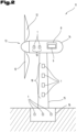
- Fig. 1 and Fig. 2 show wind turbines 11, each of which is equipped with measuring arrangements 10 according to the invention for detecting deformations, in particular bending of the outer surface, of a construction element.
- the measuring arrangements 10 formed by individual measuring points 1 are arranged on the rotor blades 12 of the rotor 13. Deviating from the features by which the invention is defined, in Fig. 2
- the measuring arrangements 10 formed by individual measuring points 1 are arranged on the nacelle 14, the tower 15 and the foundation 16.
- Various combinations and extensions of the Fig. 1 and 2 The measuring arrangements shown (including omissions of measuring arrangements or individual measuring points) are of course possible.
- the measuring arrangement comprises at least three, preferably at least five, measuring points 1 arranged on the construction element 12, which are spaced apart from one another in the direction of the longitudinal extension of the construction element 12 and each have at least one acceleration sensor 2 (see Fig. 3 and 4 ).
- the acceleration sensors 2 are connected to an evaluation device 6 via a wireless interface 5, so that the sensor data can be transmitted to the evaluation device 6, preferably immediately after they have been generated.
- the evaluation device is preferably a central evaluation device, which preferably communicates with several measuring arrangements 10, which are each arranged on different construction elements 12, 14, 15, 16.
- the evaluation device 6 can be integrated in the control device 8 of the wind turbine 11 ( Fig. 2 ) or as a separate facility or module ( Fig. 1 ).
- the measuring arrangement 10 has - in addition to the acceleration sensors 2 - at least two speed sensors 3, in particular angular velocity sensors, arranged on the construction element 12, 14, 15, 16 and spaced apart from one another in the direction of an extension, preferably the longitudinal extension, of the construction element 12, 14, 15, 16.
- the measuring arrangement 10 can have at least two position sensors 4, in particular magnetic field sensors, arranged on the construction element 12, 14, 15, 16 and spaced apart from one another in the direction of an extension, preferably the longitudinal extension, of the construction element 12, 14, 15, 16.
- the speed sensors 3 and/or the position sensors 4 are also connected to the evaluation device 6 - preferably via a wireless interface 5.
- the speed sensors 3 (like the position sensors 4) can be spaced apart from the acceleration sensors 2 ( Fig. 8 ). However, in a preferred embodiment, the additional Sensors, ie the speed sensors 3 and/or the position sensors 4, together with the acceleration sensors are each combined at a measuring point 1 ( Fig. 3 and 4 in conjunction with the Fig. 1 and 2 ).
- the at least two speed sensors 3 and/or the at least two position sensors 4 are arranged on the construction element 12, 14, 15, 16 such that the at least two measuring points 1, each of which has at least one acceleration sensor 2, additionally each have at least one speed sensor 3 and/or at least one position sensor 4 ( Fig. 3 and 4 ).
- position sensors may also be provided.
- acceleration data recorded directly on site
- speed or position data recorded directly on site
- the deformation can be recorded in the form of a deviation from the rest or normal state, as an extension or compression, as a (location) change relative to a reference point, as an oscillation (amplitude), in the form of a curvature, as one- or multi-dimensional bending parameters, as a normalized representation, as a one- or multi-dimensional deformation pattern, as a time dependence, etc. and its meaning is therefore to be interpreted broadly.
- the measuring arrangement 10 comprises at least three, preferably at least five, measuring points 1 arranged on the construction element 12, 14, 15, 16, which are spaced apart from one another in the direction of the longitudinal extension of the construction element 12, 14, 15, 16 and each have at least one acceleration sensor 2.
- Each measuring point 1 is equipped - in addition to the acceleration sensor 2 - with at least one speed sensor 3 and/or at least one position sensor 4.
- the sensor data from all sensors is transmitted to the (central) evaluation device 6.
- the distance between an acceleration sensor 2 and a speed sensor 3 and/or position sensor 4 belonging to the same measuring point 1 should be, if possible, no more than 5 cm, preferably no more than 1 cm, particularly preferably no more than 5 mm.
- At least one, preferably at least two, of the measuring points 1 are arranged in the region of the rotor blade tip and/or at a distance from the rotor blade tip that is at most as large as 20% of the total length of the rotor blade 12 (see Fig. 1 ).
- At least one measuring point 1 is arranged away from the connecting line between the outermost measuring points 1 of the measuring arrangement 10, preferably between the measuring point 1 that is closest to the rotor blade root and the measuring point 1 that is closest to the rotor blade tip.
- the normal distance from the connecting line is preferably at least 20 cm, preferably at least 50 cm.
- At least one measuring point 1 can be arranged on a first side, in particular the front side, of the construction element 12, 14, 15, 16 and at least one measuring point 1 can be arranged on a second side, opposite the first side, in particular the rear side, of the construction element 12, 14, 15, 16.
- the acceleration sensors 2 are each designed to detect the acceleration in three spatial directions.
- the respective sensor 2, 3, 4 can have three (sub)units.
- a single unit designed to measure in all three spatial directions would also be conceivable.
- Fig. 4 shows that the acceleration sensor 2 of a measuring point 1 can be integrated into a measuring unit 17 and/or accommodated in a common housing together with a speed sensor 3 belonging to the same measuring point 1 and/or a position sensor 4 belonging to the same measuring point 1.
- the measuring unit 17 has a flat base which supports the sensors 2, 3, 4.
- the flat base can be formed by a film-like and/or flexible material.
- the flat base can carry additional functional elements, such as a wireless interface 5 connected to the sensors for transmitting the sensor data to a (central) evaluation unit 6 and/or an energy conversion device 7, preferably in miniature form, for supplying the sensors 2, 3, 4 and optionally the Wireless interface 5 with (electrical) energy.
- the flat base is preferably glued to the surface of the structural element of the wind turbine 11 (to be monitored).
- each measuring point 1 is formed on a separate measuring unit 17.
- the acceleration sensors 2 and/or the speed sensors 3 and/or the position sensors 4 can be arranged, preferably glued, on an outer surface of the construction element 12, 14, 15, 16 (see e.g. Fig. 1 ).
- the measuring points 1 and/or the sensors 2, 3, 4 forming the measuring points 1 are energy self-sufficient and/or can each be connected to at least one local energy conversion device 7, which preferably converts mechanical energy, chemical energy, thermal energy and/or light into electrical energy, in particular a photovoltaic device.
- the acceleration sensors 2 and/or the speed sensors 3 and/or the position sensors 4 are preferably designed as micro-electro-mechanical systems (MEMS).
- MEMS micro-electro-mechanical systems
- the wind turbine can now be designed in such a way that a measuring arrangement 10 according to the invention is provided for at least two structural elements 12, 14, 15, 16 of the wind turbine 11, in particular for each rotor blade 12 of the rotor 13.
- the sensors 2, 3, 4 of the measuring arrangements 10 are each connected for communication to the central evaluation device 6 - preferably via a wireless interface 5.
- the control device 8 can now be configured to control the wind turbine 10 depending on the sensor signals generated by the measuring points 1 of the measuring arrangement 10, in particular to align the rotor 13 with respect to the wind direction (e.g. rotation about a vertical or almost vertical axis) and/or to adjust the pitch of the rotor blades 12.
- the method for operating a wind turbine 11, which has a rotor 13 with rotor blades 12 and at least one measuring arrangement 10 for detecting deformations, in particular bending of the outer surface, of a construction element 12, 14, 15, 16 of the wind turbine 11, in particular of a rotor blade 12, includes the following steps: by means of the at least one measuring arrangement 10, at least one construction element 12, 14, 15, 16 (e.g. on all rotor blades 12 of the rotor 13) is measured on at least two of the Acceleration data is recorded at measuring points 1 arranged on the structural element 12, 14, 15, 16, which are spaced apart from one another in the direction of an extension, preferably the longitudinal extension of the structural element 12, 14, 15, 16. In addition, speed data and/or position data are recorded at at least two points arranged on the structural element 12, 14, 15, 16 and spaced apart from one another in the direction of an extension, preferably the longitudinal extension of the structural element 12, 14, 15, 16.
- the acceleration data are linked to the speed data and/or position data to determine the deformations of the structural element 12, 14, 15, 16. This is preferably done by an algorithm.
- the linking and determination of the deformations is preferably carried out by the evaluation device 6.
- the speed data and/or position data are recorded at the same measuring points 1 at which the acceleration data are recorded.
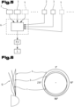
- Fig. 6 shows a rotor blade in different deformation states a, b and c and to the right of it the effective radius along a complete revolution, i.e. depending on the rotor rotation angle.
- the effective radius is obtained by projecting the bent rotor blade - in the direction of the rotor's axis of rotation - into the non-bent rotor blade.
- State a means “no deformation” (rest state)
- state b means “constant deformation”
- state c means asymmetric deformation, e.g. in the case of wind shear.
- Such deformation patterns can be recognized as follows.
- Fig. 7 shows the procedure schematically.
- the (absolute or relative) positions x1(t), x2(t), ... of the individual measuring points are determined from the acceleration data a1(t), a2(t), ... and the speed data v1(t), v2(t), ... of the individual measuring points with the designation 1, 2, ... by applying an algorithm A.
- position data e.g. with information about the orientation
- the deformation V (bending, torsion, vibrations, etc.) can be determined from these positions x1(t), x2(t), ... of the individual measuring points.
- the position of the measuring point 1 is determined from the acceleration data recorded at a measuring point 1 and the speed data and/or position data recorded at the same measuring point 1, wherein the determined position of the measuring point 1 can be a relative position to a reference point, in particular the rotor blade root and/or the rotor axis, and/or an absolute position.
- R x is the rotation matrix of a measuring point around the x-axis due to the pitch.
- R z is the rotation matrix of the measuring point around the z-axis due to the orientation of the rotor or the measuring point.
- R y is the rotation matrix of the measuring point around the y-axis, which corresponds to the rotation of the rotor 13 around its axis of rotation.
- the speeds in particular, but possibly also the positions or orientations of the measuring point, in particular in the form of the rotation matrices are of significant importance in modelling the acceleration or the deformation to be recorded.
- the inventive concept of measuring the speeds and/or positions directly on site - i.e. directly on the moving, vibrating or other deformation-exposed construction element itself, preferably concentrated at one measuring point each - can significantly increase the accuracy of the deformation recording.
- the treatment of a measuring point - e.g. using a model or algorithm - can be carried out individually and based on the data recorded directly at the measuring point (acceleration data as well as speed and/or position data).
- the acceleration data as well as the speed data and/or position data can be recorded continuously, wherein preferably the deformations of the structural element 12, 14, 15, 16 are also determined continuously.
- the deformation of the structural element in particular a bending curve along an extension, preferably the longitudinal extension of the structural element, can be determined from the determined positions of several measuring points 1. This is preferably done in 3 dimensions.
- the quantities shown schematically in Fig. 17 are in this case vectors or matrices.
- the positions of the measuring points 1 can also be determined as a function of time from the determined acceleration data as well as the speed data and/or position data.
- the deformations of the structural element 12, 14, 15, 16 can also be determined as a function of time and/or as a function of the angle of rotation of the rotor 13.
- control commands S can be generated depending on the determined positions (of the measuring points) and deformations V of the structural element, which are forwarded by the evaluation device 6 and/or control device 8 to corresponding actuators of the wind turbine 11.
- Fig. 6 it can be seen that in state c an asymmetrical deformation (ie one dependent on the angle of rotation) occurs.
- the control of the wind turbine 11 can now be carried out in such a way that the pitch of one or more rotor blades 12 is adjusted depending on the angle of rotation of the rotor 13 in order to counteract such an asymmetrical deformation as best as possible.
- the angle of rotation means that (at least two, preferably any number) different settings can be made within one revolution of the rotor.
- a comparison of the determined accelerations, speeds and/or positions of the individual measuring points 1 and/or the determined deformations of the structural element 12, 14, 15, 16, in particular of the rotor blade 12, can be carried out with a model, wherein preferably deviations from the model are used to recognize deformation patterns.
- the determined deformations can also be compared with a number of stored deformation patterns, which can include bending shapes and/or temporal dependencies in particular.
- the deformation pattern that shows the smallest deviations from the determined deformations can be selected.
- At least one predetermined setting of the wind turbine 11 can be assigned to each of the stored deformation patterns.
- the setting assigned to the selected deformation pattern in particular a specific orientation of the rotor 13 with respect to the wind direction and/or a setting of the pitch of the rotor blades 12, is then carried out and/or maintained.
- a self-learning algorithm can be stored in the control device 8, which is designed to adapt and/or maintain settings, in particular setting parameters, of the wind turbine 11 based on one or more deformation patterns, preferably based on deformation patterns determined at time intervals, wherein the self-learning algorithm preferably uses stored reference data with deformation patterns and/or settings.
- the following variants relate to the preferred possibility of bringing the sensors belonging to different, spaced-apart measuring points into synchronization in time.
- the sensors 2, 3, 4 of the various measuring points 1 can thus be synchronized in time by the evaluation device 6 - preferably by means of a signal sent from the evaluation device 6 to the sensors 2, 3, 4, in particular in the form of a data packet - in particular with regard to the time of the measurement carried out by the respective sensors 2, 3, 4 and/or the time of the transmission of the sensor data from the sensors 2, 3, 4 to the evaluation device 6.
- the evaluation device 6 is designed to transmit a signal to the sensors 2, 3, 4 of the measuring points 1, by means of which the sensors 2, 3, 4 of the various measuring points 1 are synchronized in time, so that the sensors 2, 3, 4 synchronized in this way each carry out at least one measurement within a common time window, which is preferably at most 500 ⁇ s, preferably at most 100 ⁇ s, particularly preferably at most 50 ⁇ s.
- the sensors are brought into synchronization with each other via data packets sent by the base so that they measure simultaneously within a tolerance of preferably ⁇ 100 ⁇ s, in an advantageous design ⁇ 50 ⁇ s or less. This makes almost the same simultaneous sampling possible at several positions - even when the transmission between the base/evaluation device is wireless and the sensors are independent of each other (i.e. in the case of sensors that do not communicate with each other or at least do not necessarily communicate with each other).
- the determination of the size(s) and/or property(s) preferably comprises a comparison between current (sensor) data and historical (sensor) data and/or a comparison between the (sensor) data of one rotor blade and the (sensor) data of at least one other rotor blade.
- the measurement of the torsion of the blades can be carried out statically, dynamically and/or the individual rotor blades in relation to each other. Blade loads and load cycles can also be determined in this way. Vibration patterns can also be measured locally, globally and/or in relation to the individual rotor blades in relation to each other. This can be used to identify, for example, a source of increased noise emissions or an early sign of damage or a faulty control state. Furthermore, detection/characterization of shear winds, turbulence, gusts, oblique flow and/or incorrect azimuth angles of the wind turbine is possible. Blade damage can be detected, for example, from a change in the vibration behavior of the rotor blade (e.g. by comparing a sensor position with historical data at the same position or comparing a radial position with current data obtained from other rotor blades).
- the evaluation device 6 is preferably designed to determine the deformations and/or the sizes and/or properties from those sensor data which were recorded by the synchronized sensors 2, 3, 4 within a common time window, which is preferably at most 500 ⁇ s, preferably at most 100 ⁇ s, particularly preferably at most 50 ⁇ s.
Landscapes
- Engineering & Computer Science (AREA)
- Physics & Mathematics (AREA)
- General Physics & Mathematics (AREA)
- Sustainable Energy (AREA)
- Chemical & Material Sciences (AREA)
- Combustion & Propulsion (AREA)
- Mechanical Engineering (AREA)
- General Engineering & Computer Science (AREA)
- Life Sciences & Earth Sciences (AREA)
- Sustainable Development (AREA)
- Aviation & Aerospace Engineering (AREA)
- Wind Motors (AREA)
- Length Measuring Devices With Unspecified Measuring Means (AREA)
- Arrangements For Transmission Of Measured Signals (AREA)
Claims (15)
- Dispositif de mesure (10) pour la mesure de déformations, plus particulièrement de flexions, de la surface externe d'un élément de construction (12, 14, 15, 16) d'une éolienne (11), dans lequel l'élément de construction est une pale de rotor (12) de l'éolienne (11), comprenant :au moins trois, de préférence au moins cinq, points de mesure (1) disposés sur l'élément de construction (12, 14, 15, 16), qui sont distants entre eux dans la direction de l'extension longitudinale de l'élément de construction (12) et qui comprennent chacun au moins un capteur d'accélération (2),dans lequel les capteurs d'accélération (2) peuvent être reliés en communication avec un dispositif d'analyse (6), de préférence par l'intermédiaire d'une interface sans fil (5),caractérisé en ce que le dispositif de mesure (10) comprend au moins deux capteurs de vitesse (3), plus particulièrement des capteurs de vitesse angulaire, disposés sur l'élément de construction (12) et distants entre eux dans la direction de l'extension longitudinale de l'élément de construction (12),et/ou en ce que le dispositif de mesure (10) comprend au moins deux capteurs de position (4), plus particulièrement des capteurs de champ magnétique, disposés sur l'élément de construction (12) et distants entre eux dans la direction de l'extension longitudinale de l'élément de construction (12),dans lequel les points de mesure (1) comprennent chacun, en plus du capteur d'accélération (2), au moins un capteur de vitesse (3) et/ou au moins un capteur de position (4) etdans lequel les capteurs de vitesse (3) et/ou les capteurs de position (4) peuvent être reliés en communication avec le dispositif d'analyse (6), de préférence par l'intermédiaire d'une interface sans fil (5),et en ce qu'au moins un, de préférence au moins deux, des points de mesure (1) est/sont disposé(s) au niveau de la pointe de la pale de rotor et/ou à une distance de la pointe de pale de rotor, qui est plus grande que 20 % de la longueur totale de la pale du rotor (12), et en ce queau moins un point de mesure (1) est disposé à l'écart des droites de liaison entre les points de mesure (1) les plus extérieurs du dispositif de mesure (10), de préférence entre le point de mesure (1), qui est le plus proche de la base de la pale de rotor et le point de mesure (1) qui est le plus proche de la point de la pale de rotor, dans lequel, de préférence, la distance normale par rapport aux droites de liaison est égale à au moins 20 cm, de préférence au moins 50 cm et/ou représente au moins 0,5 %, de préférence au moins 1 % de l'extension longitudinale de l'élément de construction (12),et/ou en ce qu'au moins un point de mesure (1) est disposé sur une première face, plus particulièrement la face avant, de l'élément de construction (12) et au moins un point de mesure (1) est disposé sur une deuxième face opposée à la première face, plus particulièrement la face arrière, de l'élément de construction (12).
- Dispositif de mesure selon la revendication 1, caractérisé en ce que la distance entre un capteur d'accélération (2) et un capteur de vitesse (3) et/ou capteur de position (4) appartenant au même point de mesure (1) est égale à 5 cm maximum, de préférence 1 cm maximum, plus particulièrement de préférence 5 mm maximum,
et/ou en ce que le capteur d'accélération (2) d'un point de mesure (1) est intégré, conjointement avec un capteur de vitesse (3) appartenant au même point de mesure (1) et/ou un capteur de position (4) appartenant au même point de mesure (1), dans une unité de mesure (17) et/ou est logé dans un boîtier commun. - Dispositif de mesure selon l'une des revendications précédentes, caractérisé en ce que les capteurs d'accélération (2) sont conçus respectivement pour la mesure de l'accélération dans 3 directions de l'espace et/ou en ce que les capteurs de vitesse (3) sont conçus respectivement pour la mesure de la vitesse dans 3 directions de l'espace et/ou en ce que les capteurs de position (4) sont conçus respectivement pour la mesure de la position ou de l'orientation dans 3 directions de l'espace.
- Dispositif de mesure selon l'une des revendications précédentes, caractérisé en ce que l'unité de mesure (17) présente une base plane, qui supporte les capteurs (2, 3, 4), dans lequel, de préférence, la base plane est constituée d'un matériau de type film et/ou flexible et supporte, de préférence, au moins un élément fonctionnel supplémentaire, plus particulièrement une interface sans fil (5) reliée avec les capteurs (2, 3, 4), pour la transmission des données des capteurs à une unité d'analyse (6) et/ou un dispositif de conversion d'énergie (7) pour l'alimentation des capteurs (2, 3, 4) en énergie, dans lequel, de préférence, la base plane est collée à la surface de la pale de rotor (12) de l'éolienne (11).
- Dispositif de mesure selon l'une des revendications précédentes, caractérisé en ce que les capteurs d'accélération (2) et/ou les capteurs de vitesse (3) et/ou les capteurs de position (4) sont disposés, de préférence collés, sur une surface externe de la pale de rotor (12) et/ou en ce que les capteurs d'accélération (2) et/ou les capteurs de vitesse (3) et/ou les capteurs de position (4) sont conçus comme des système micro-électro-mécaniques (MEMS).
- Dispositif de mesure selon l'une des revendications précédentes, caractérisé en ce que le dispositif d'analyse (6) est conçu pour combiner les données d'accélération des capteurs d'accélération (2) avec les données de vitesse des capteurs de vitesse (3) et/ou les données de position des capteurs de position (4) et en déduire les déformations de l'élément de construction (12).
- Dispositif de mesure selon l'une des revendications précédentes, caractérisé en ce que les capteurs (2, 3, 4) des différents points de mesure (1) du dispositif de mesure (10) peuvent être synchronisés dans le temps par le dispositif d'analyse, de préférence au moyen d'un signal envoyé aux capteurs (2, 3, 4) par le dispositif d'analyse (6), plus particulièrement sous la forme d'un paquet de données, plus particulièrement en ce qui concerne le moment de la mesure effectuée par les capteurs (2, 3, 4) respectifs et/ou le moment de la transmission des données de capteurs au dispositif d'analyse (6) par les capteurs (2, 3, 4).
- Dispositif de mesure selon l'une des revendications précédentes, caractérisé en ce que le dispositif d'analyse (6) est conçu pour transmettre aux capteurs (2, 3, 4) des points de mesure (1) un signal à l'aide duquel les capteurs (2, 3, 4) des différents points de mesure (1) sont synchronisés dans le temps, de sorte que les capteurs (2, 3, 4) ainsi synchronisés effectuent chacun, dans une fenêtre de temps commune, qui est égale, de préférence à 500 µs maximum, de préférence à 100 µs maximum, plus particulièrement de préférence à 50 µs maximum, au moins une mesure,
et/ou en ce que le dispositif d'analyse (6) est conçu pour déterminer les déformations et/ou les grandeurs et/ou les propriétés à partir des données de capteurs qui ont été enregistrées par les capteurs (2, 3, 4) synchronisés dans une fenêtre de temps commune, qui est égale, de préférence à 500 µs maximum, de préférence à 100 µs maximum, plus particulièrement de préférence à 50 µs maximum. - Dispositif de mesure selon l'une des revendications précédentes, caractérisé en ce que le dispositif d'analyse est conçu pour déterminer, à partir des données des capteurs (2, 3, 4), plus particulièrement par combinaison des données d'accélération des capteurs d'accélération (2) avec les données de vitesse des capteurs de vitesse (3) et/ou des données de position des capteurs de position (4), au moins une, de préférence plusieurs, des grandeurs et/ou propriétés suivantes :- l'angle d'inclinaison absolu d'au moins une pale de rotor et/ou- l'angle d'inclinaison relatif d'au moins deux pales de rotor l'une par rapport à l'autre et/ou- la torsion d'au moins une pale de rotor et/ou d'au moins deux pales de rotor l'une par rapport à l'autre et/ou- la charge et/ou le cycle de charge agissant sur au moins une pale de rotor et/ou- une source d'émissions sonores accrues et/ou- un signe précoce d'un dommage ou d'un état de régulation erroné de l'éolienne et/ou- le type, la force, la dynamique et/ou la direction des vents et/ou- une variation du comportement vibratoire de l'élément de construction et/ou- un endommagement de la pale de rotor,dans lequel, de préférence, la détermination de la ou des grandeur(s) et/ou propriété(s) comprend une comparaison entre des données actuelles et des données historiques et/ou une comparaison entre les données d'une pale de rotor et les données d'au moins une autre pale de rotor.
- Éolienne (11) comprenantun rotor (13) avec au moins deux, de préférence trois, pales de rotor (12) etau moins un dispositif de mesure (10) pour la mesure de déformation d'au moins un élément de construction de l'éolienne (11), dans lequel l'élément de construction est une pale de rotor (12) de l'éolienne (11) etun dispositif de commande (8),caractérisée en ce que l'au moins un dispositif de mesure (10) est conçu selon l'une des revendications précédentes.
- Éolienne selon la revendication 10, caractérisée en ce que, pour au moins deux pales de rotor (12) de l'éolienne (11), plus particulièrement pour chaque pale de rotor (12) du rotor (13), est prévu un dispositif de mesure (10) selon l'une des revendications 1 à 9, dans lequel, de préférence, les capteurs (2, 3, 4) des dispositifs de mesure (10) sont reliés en communication avec un dispositif d'analyse central (6), de préférence par l'intermédiaire d'une interface sans fil (5),
et/ou en ce que le dispositif de commande (8) est conçu pour contrôler l'éolienne (10) en fonction des signaux de capteurs générés par les points de mesure (1) du dispositif de mesure (10), plus particulièrement pour orienter le rotor (13) en fonction de la direction du vent et/ou pour ajuster l'angle d'inclinaison des pales de rotor (12). - Procédé de fonctionnement d'une éolienne (11), qui comprend un rotor (13) avec des pales de rotor (12) et au moins un dispositif de mesure (10) pour la mesure de déformations, plus particulièrement de flexions de la surface externe d'un élément de construction de l'éolienne (11), cet élément de construction étant une pale de rotor (12), dans lequel, au moyen de l'au moins un dispositif de mesure (10) sur au moins une pale de rotor (12), de préférence respectivement sur toutes les pales de rotor (12) du rotor (13), au niveau d'au moins deux points de mesure (1) disposés sur la pale de rotor (12), qui sont distants entre eux dans la direction d'une extension, de préférence l'extension longitudinale, de la pale de rotor (12), des données d'accélération sont relevées,caractérisé en ce que, au niveau d'au moins deux points disposés sur la pale de rotor (12) et distants entre eux dans la direction de l'extension longitudinale de la pale de rotor (12), des données de vitesse et/ou des données de position sont relevées, dans lequel, de préférence, les données de vitesse et/ou les données de position sont relevées au niveau des mêmes points de mesure (1) que ceux au niveau desquels les données d'accélération sont relevées,et en ce que les données d'accélération sont combinées avec les données de vitesse et/ou les données de position afin de déterminer les déformations de la pale de rotor (12), de préférence à l'aide d'un dispositif d'analyse (6) relié en communication avec les capteurs (2, 3, 4) et en ce que le dispositif de mesure (10) est conçu selon l'une des revendications 1 à 9 et/ou l'éolienne (11) est conçue selon l'une des revendications 10 à 11.
- Procédé selon la revendication 12, caractérisé en ce que, à partir des données d'accélération relevées au niveau d'un point de mesure (1) et des données de vitesse et/ou des données de position relevées au niveau du même point de mesure (1), la position du point de mesure (1) est déterminée, dans lequel la position déterminée du point de mesure (1) est une position relative par rapport à un point de référence, plus particulièrement la base de la pale de rotor et/ou l'axe du rotor et/ou est une position absolue, dans lequel, de préférence, à partir des positions déterminées de plusieurs points de mesure (1), la déformation de l'élément de construction (12), plus particulièrement une évolution de la flexion le long d'une extension, de préférence l'extension longitudinale, de l'élément de construction (12), est déterminée, dans lequel, de préférence, la déformation de l'élément de construction (12) est déterminée dans 3 dimensions.
- Procédé selon la revendication 12 ou 13, caractérisé en ce que, à partir des données d'accélération ainsi que des données de vitesse et/ou des données de position déterminées, les positions des points de mesure (1) sont déterminées en fonction du temps et/ou en ce que les déformations de l'élément de construction (12) sont déterminées en fonction du temps et/ou en fonction de l'angle de rotation du rotor (13) et/ou en ce que le contrôle de l'éolienne (11) est effectué de sorte que le réglage de l'inclinaison d'une ou de plusieurs pales de rotor (12) est effectué en fonction de l'angle de rotation du rotor (13).
- Procédé selon l'une des revendications 12 à 14, caractérisé en ce qu'une comparaison des accélérations, vitesses et/ou positions déterminées des différents points de mesures (1) et/ou des déformations déterminées de la pale de rotor (12), avec un modèle, est effectuée, dans lequel, de préférence, les écarts par rapport au modèle sont utilisés pour la détection de motifs de déformations,
et/ou en ce que les déformations déterminées sont comparées avec plusieurs motifs de déformations enregistrés, qui peuvent comprend, plus particulièrement des formes de flexion et/ou des dépendances en fonction du temps, dans lequel, de préférence, le motif de déformation sélectionné est celui qui présente les écarts les plus faibles par rapport aux déformations déterminées.
Applications Claiming Priority (2)
| Application Number | Priority Date | Filing Date | Title |
|---|---|---|---|
| ATA50683/2020A AT523919B1 (de) | 2020-08-14 | 2020-08-14 | Messvorrichtung für Windkraftanlagen |
| PCT/AT2021/060282 WO2022032321A1 (fr) | 2020-08-14 | 2021-08-12 | Dispositif de mesure pour éoliennes |
Publications (3)
| Publication Number | Publication Date |
|---|---|
| EP4196678A1 EP4196678A1 (fr) | 2023-06-21 |
| EP4196678C0 EP4196678C0 (fr) | 2024-10-09 |
| EP4196678B1 true EP4196678B1 (fr) | 2024-10-09 |
Family
ID=77738890
Family Applications (1)
| Application Number | Title | Priority Date | Filing Date |
|---|---|---|---|
| EP21769631.9A Active EP4196678B1 (fr) | 2020-08-14 | 2021-08-12 | Dispositif de mesure pour éoliennes |
Country Status (6)
| Country | Link |
|---|---|
| US (1) | US20230258162A1 (fr) |
| EP (1) | EP4196678B1 (fr) |
| JP (1) | JP2023538887A (fr) |
| AT (1) | AT523919B1 (fr) |
| CA (1) | CA3190614A1 (fr) |
| WO (1) | WO2022032321A1 (fr) |
Families Citing this family (7)
| Publication number | Priority date | Publication date | Assignee | Title |
|---|---|---|---|---|
| SE545911C2 (en) * | 2021-11-05 | 2024-03-12 | Sigicom Ab | A wind turbine, a measurement system for a wind turbine system and method for providing measurement data |
| CN115750229A (zh) * | 2022-11-10 | 2023-03-07 | 中国华能集团清洁能源技术研究院有限公司 | 一种基于多源传感的风电机组全状态监测系统 |
| CN115854856B (zh) * | 2022-11-22 | 2025-12-19 | 明阳智慧能源集团股份公司 | 一种风力发电机组叶片变形状态监测方法 |
| DE102022214018A1 (de) * | 2022-12-20 | 2024-06-20 | Fraunhofer-Gesellschaft zur Förderung der angewandten Forschung eingetragener Verein | Anordnung und Verfahren zur Überwachung eines elektrisch angetriebenen Systems und System, insbesondere Windenergieanlage, mit einer solchen Anordnung |
| DE102023124425A1 (de) * | 2023-09-11 | 2025-03-13 | Weidmüller Monitoring Systems Gmbh | Verfahren und Vorrichtung zur Zustandsüberwachung einer Windenergieanlage mittels Schwingungsanalyse |
| WO2025201641A1 (fr) | 2024-03-27 | 2025-10-02 | Aeomiq Gmbh | Élément chauffant pour un système de protection contre la glace ; pièces équipées de celui-ci et procédé de fonctionnement |
| CN121088590A (zh) * | 2025-11-06 | 2025-12-09 | 华能吉林新能源开发有限公司 | 叶片表面结冰检测装置、风力发电机组及其除冰方法 |
Citations (1)
| Publication number | Priority date | Publication date | Assignee | Title |
|---|---|---|---|---|
| US20120303277A1 (en) * | 2011-05-27 | 2012-11-29 | Xu Fu | Wind turbine and method for determining parameters of wind turbine |
Family Cites Families (21)
| Publication number | Priority date | Publication date | Assignee | Title |
|---|---|---|---|---|
| CA2426711C (fr) * | 2002-05-02 | 2009-11-17 | General Electric Company | Centrale eolienne, mecanisme de commande de centrale eolienne et methode d'exploitation d'une centrale eolienne |
| WO2010046403A2 (fr) * | 2008-10-23 | 2010-04-29 | Vestas Wind Systems A/S | Éolienne et procédé de surveillance d'éolienne |
| US20100140936A1 (en) * | 2008-12-23 | 2010-06-10 | General Electric Company | Wind turbine with gps load control |
| DE102009058595A1 (de) * | 2009-12-17 | 2011-06-22 | Siemens Aktiengesellschaft, 80333 | Detektion einer Verformung eines Flügels einer Windkraftanlage |
| DE102010032120A1 (de) | 2010-07-24 | 2012-01-26 | Robert Bosch Gmbh | Verfahren und Vorrichtung zur Bestimmung eines Biegewinkels eines Rotorblattes einer Windkraftanlage |
| US9447778B2 (en) * | 2011-11-02 | 2016-09-20 | Vestas Wind Systems A/S | Methods and systems for detecting sensor fault modes |
| US8511177B1 (en) * | 2011-12-15 | 2013-08-20 | Shaw Shahriar Makaremi | Blade condition monitoring system |
| WO2013110215A1 (fr) * | 2012-01-27 | 2013-08-01 | General Electric Company | Éolienne et procédé de détermination de paramètres d'éolienne |
| JP6037302B2 (ja) * | 2012-05-01 | 2016-12-07 | 国立大学法人東京工業大学 | 風力発電装置 |
| DE102012108776A1 (de) * | 2012-09-18 | 2014-03-20 | Technische Universität München | Verfahren und Vorrichtung zur Überwachung von Betriebszuständen von Rotorblättern |
| DE102013014622A1 (de) * | 2013-09-02 | 2015-03-05 | Northrop Grumman Litef Gmbh | System und Verfahren zum Bestimmen von Bewegungen und Schwingungen bewegter Strukturen |
| DE102014117918A1 (de) * | 2014-12-04 | 2016-06-09 | fos4X GmbH | Verfahren zur individuellen Pitchregelung von Rotorblättern einer Windkraftanlage, Beschleunigungssensor für ein Rotorblatt, Rotorblatt mit Beschleunigungssensor, ein Rotor einer Windkraftanlage und Windkraftanlagen |
| ES2923904T3 (es) * | 2014-12-23 | 2022-10-03 | Vestas Wind Sys As | Método y sistema para determinar la torsión dinámica de una pala de turbina eólica |
| JP6546803B2 (ja) * | 2015-07-22 | 2019-07-17 | 株式会社日立製作所 | 風力発電装置及び風力発電装置における無線通信方法 |
| DE102015011761B4 (de) * | 2015-09-15 | 2018-05-09 | Jörn GmbH | Windenergieanlage mit wenigstens einem elastisch verformbaren Bauteil und Verfahren zur Feststellung des Beginns einer verschleißbedingten Bauteil-Restnutzungsdauer in einer Windenergieanlage |
| EP3260700A1 (fr) * | 2016-06-22 | 2017-12-27 | Siemens Aktiengesellschaft | Procédé informatisé et dispositif de prévision pour données de fonctionnement d'une éolienne |
| DE102017115926B4 (de) * | 2017-07-14 | 2022-03-17 | fos4X GmbH | Blattbiegemomentbestimmung mit zwei Lastsensoren pro Rotorblatt und unter Einbezug von Rotordaten |
| TWI647386B (zh) * | 2017-12-22 | 2019-01-11 | 財團法人船舶暨海洋產業研發中心 | 離岸風機支撐結構監測系統及其運作方法 |
| EP3561295B1 (fr) * | 2018-04-23 | 2020-11-04 | Wölfel Engineering GmbH & Co. KG. | Procédé de détermination d'un balourd aérodynamique d'un rotor d'une éolienne |
| DE102018112825A1 (de) * | 2018-05-29 | 2019-12-05 | fos4X GmbH | Sensoranordnung für eine Windkraftanlage |
| DE102018119733B4 (de) * | 2018-08-14 | 2022-10-06 | fos4X GmbH | Bestimmung des Torsionswinkels und Pitchwinkelbestimmung mittels mindestens zwei Beschleunigungssensoren |
-
2020
- 2020-08-14 AT ATA50683/2020A patent/AT523919B1/de active
-
2021
- 2021-08-12 US US18/020,534 patent/US20230258162A1/en not_active Abandoned
- 2021-08-12 EP EP21769631.9A patent/EP4196678B1/fr active Active
- 2021-08-12 WO PCT/AT2021/060282 patent/WO2022032321A1/fr not_active Ceased
- 2021-08-12 JP JP2023511611A patent/JP2023538887A/ja active Pending
- 2021-08-12 CA CA3190614A patent/CA3190614A1/fr active Pending
Patent Citations (1)
| Publication number | Priority date | Publication date | Assignee | Title |
|---|---|---|---|---|
| US20120303277A1 (en) * | 2011-05-27 | 2012-11-29 | Xu Fu | Wind turbine and method for determining parameters of wind turbine |
Also Published As
| Publication number | Publication date |
|---|---|
| US20230258162A1 (en) | 2023-08-17 |
| JP2023538887A (ja) | 2023-09-12 |
| AT523919A4 (de) | 2022-01-15 |
| EP4196678C0 (fr) | 2024-10-09 |
| AT523919B1 (de) | 2022-01-15 |
| WO2022032321A1 (fr) | 2022-02-17 |
| CA3190614A1 (fr) | 2022-02-17 |
| EP4196678A1 (fr) | 2023-06-21 |
Similar Documents
| Publication | Publication Date | Title |
|---|---|---|
| EP4196678B1 (fr) | Dispositif de mesure pour éoliennes | |
| EP2426352B1 (fr) | Méthode de régulation de la vitesse de rotation d'une éolienne | |
| EP2479425B1 (fr) | Procédé de surveillance d'une stabilité statique et/ou dynamique d'une éolienne | |
| DE102010006544B4 (de) | Rotorblatt für eine Windenergieanlage und Verfahren zur Dämpfung von Schwingungen eines Rotorblatts | |
| EP2665930B1 (fr) | Procédé de détermination de l'inclinaison d'une tour | |
| EP2596238A2 (fr) | Procédé et dispositif de détermination d'un angle de flexion d'une pale de rotor d'une éolienne | |
| DE102005016524A1 (de) | Verfahren und Vorrichtung zur Erkennung von Rotorblatteis | |
| DE102013014622A1 (de) | System und Verfahren zum Bestimmen von Bewegungen und Schwingungen bewegter Strukturen | |
| DE10219664A1 (de) | Windenergieanlage, Regelanordnung für eine Windenergieanlage und Verfahren zum Betreiben einer Windenergieanlage | |
| DE102009025778A1 (de) | Verfahren und Vorrichtung zum Messen von Parametern von Rotorflügeln | |
| EP3555466B1 (fr) | Dispositif et procédé de détection de l'accumulation de glace à une structure d'un ouvrage de construction | |
| EP2047098A2 (fr) | Procédé de calibrage | |
| EP2553263A2 (fr) | Dispositif de commande pour éolienne | |
| EP3298272B1 (fr) | Dispositif de mesure situé sur une éolienne | |
| EP3458713A1 (fr) | Procédé de détermination d'une oscillation d'une tour d'éolienne | |
| EP4325048B1 (fr) | Procédé mis en oeuvre par ordinateur et dispositif d'ajustement d'un système de mesure de charge de pale d'une pale de rotor d'une éolienne, éolienne pourvue d'au moins une pale de rotor doté d'un capteur de déformation et support de stockage lisible par ordinateur | |
| EP4086454A1 (fr) | Procédé de fonctionnement d'une éolienne, éolienne et parc éolien | |
| WO2011026616A1 (fr) | Dispositif pour mesurer et/ou enregistrer des distances et des variations de distance et dispositif pour mesurer et/ou enregistrer des contraintes mécaniques | |
| EP3692258B1 (fr) | Procédé d'étalonnage d'un capteur de pression d'une éolienne et éolienne comportant un dispositif d'étalonnage d'un capteur de pression | |
| WO2015091179A1 (fr) | Procédé et dispositif de régulation du pas des pales d'un rotor d'une éolienne | |
| DE102008003632A1 (de) | Drehzahlerfassung an einer Windenergieanlage | |
| DE102007020076B4 (de) | Windmesssystem für eine Windenergieanlage | |
| DE102012015456A1 (de) | Vorrichtung und Verfahren zum Erfassen einer Verformung zumindest eines Rotorblatts eines Rotors einer Windenergieanlage | |
| EP3553311A1 (fr) | Dispositif et procédé de commande d'une éolienne | |
| DE102011121439A1 (de) | Messvorrichtung und Verfahren zum Erfassen einer Belastung eines Rotorblatts und Regelsystem zum Ansteuern des Rotorblatts |
Legal Events
| Date | Code | Title | Description |
|---|---|---|---|
| STAA | Information on the status of an ep patent application or granted ep patent |
Free format text: STATUS: UNKNOWN |
|
| STAA | Information on the status of an ep patent application or granted ep patent |
Free format text: STATUS: THE INTERNATIONAL PUBLICATION HAS BEEN MADE |
|
| PUAI | Public reference made under article 153(3) epc to a published international application that has entered the european phase |
Free format text: ORIGINAL CODE: 0009012 |
|
| STAA | Information on the status of an ep patent application or granted ep patent |
Free format text: STATUS: REQUEST FOR EXAMINATION WAS MADE |
|
| 17P | Request for examination filed |
Effective date: 20230313 |
|
| AK | Designated contracting states |
Kind code of ref document: A1 Designated state(s): AL AT BE BG CH CY CZ DE DK EE ES FI FR GB GR HR HU IE IS IT LI LT LU LV MC MK MT NL NO PL PT RO RS SE SI SK SM TR |
|
| DAV | Request for validation of the european patent (deleted) | ||
| DAX | Request for extension of the european patent (deleted) | ||
| GRAP | Despatch of communication of intention to grant a patent |
Free format text: ORIGINAL CODE: EPIDOSNIGR1 |
|
| STAA | Information on the status of an ep patent application or granted ep patent |
Free format text: STATUS: GRANT OF PATENT IS INTENDED |
|
| GRAJ | Information related to disapproval of communication of intention to grant by the applicant or resumption of examination proceedings by the epo deleted |
Free format text: ORIGINAL CODE: EPIDOSDIGR1 |
|
| STAA | Information on the status of an ep patent application or granted ep patent |
Free format text: STATUS: REQUEST FOR EXAMINATION WAS MADE |
|
| INTG | Intention to grant announced |
Effective date: 20240301 |
|
| INTC | Intention to grant announced (deleted) | ||
| GRAP | Despatch of communication of intention to grant a patent |
Free format text: ORIGINAL CODE: EPIDOSNIGR1 |
|
| STAA | Information on the status of an ep patent application or granted ep patent |
Free format text: STATUS: GRANT OF PATENT IS INTENDED |
|
| INTG | Intention to grant announced |
Effective date: 20240506 |
|
| RAP3 | Party data changed (applicant data changed or rights of an application transferred) |
Owner name: EOLOGIX SENSOR TECHNOLOGY GMBH |
|
| GRAS | Grant fee paid |
Free format text: ORIGINAL CODE: EPIDOSNIGR3 |
|
| GRAA | (expected) grant |
Free format text: ORIGINAL CODE: 0009210 |
|
| STAA | Information on the status of an ep patent application or granted ep patent |
Free format text: STATUS: THE PATENT HAS BEEN GRANTED |
|
| AK | Designated contracting states |
Kind code of ref document: B1 Designated state(s): AL AT BE BG CH CY CZ DE DK EE ES FI FR GB GR HR HU IE IS IT LI LT LU LV MC MK MT NL NO PL PT RO RS SE SI SK SM TR |
|
| REG | Reference to a national code |
Ref country code: CH Ref legal event code: EP |
|
| REG | Reference to a national code |
Ref country code: DE Ref legal event code: R096 Ref document number: 502021005457 Country of ref document: DE |
|
| REG | Reference to a national code |
Ref country code: IE Ref legal event code: FG4D Free format text: LANGUAGE OF EP DOCUMENT: GERMAN |
|
| U01 | Request for unitary effect filed |
Effective date: 20241108 |
|
| U07 | Unitary effect registered |
Designated state(s): AT BE BG DE DK EE FI FR IT LT LU LV MT NL PT RO SE SI Effective date: 20241218 |
|
| PG25 | Lapsed in a contracting state [announced via postgrant information from national office to epo] |
Ref country code: IS Free format text: LAPSE BECAUSE OF FAILURE TO SUBMIT A TRANSLATION OF THE DESCRIPTION OR TO PAY THE FEE WITHIN THE PRESCRIBED TIME-LIMIT Effective date: 20250209 Ref country code: HR Free format text: LAPSE BECAUSE OF FAILURE TO SUBMIT A TRANSLATION OF THE DESCRIPTION OR TO PAY THE FEE WITHIN THE PRESCRIBED TIME-LIMIT Effective date: 20241009 |
|
| PG25 | Lapsed in a contracting state [announced via postgrant information from national office to epo] |
Ref country code: ES Free format text: LAPSE BECAUSE OF FAILURE TO SUBMIT A TRANSLATION OF THE DESCRIPTION OR TO PAY THE FEE WITHIN THE PRESCRIBED TIME-LIMIT Effective date: 20241009 |
|
| PG25 | Lapsed in a contracting state [announced via postgrant information from national office to epo] |
Ref country code: NO Free format text: LAPSE BECAUSE OF FAILURE TO SUBMIT A TRANSLATION OF THE DESCRIPTION OR TO PAY THE FEE WITHIN THE PRESCRIBED TIME-LIMIT Effective date: 20250109 |
|
| PG25 | Lapsed in a contracting state [announced via postgrant information from national office to epo] |
Ref country code: GR Free format text: LAPSE BECAUSE OF FAILURE TO SUBMIT A TRANSLATION OF THE DESCRIPTION OR TO PAY THE FEE WITHIN THE PRESCRIBED TIME-LIMIT Effective date: 20250110 |
|
| PG25 | Lapsed in a contracting state [announced via postgrant information from national office to epo] |
Ref country code: PL Free format text: LAPSE BECAUSE OF FAILURE TO SUBMIT A TRANSLATION OF THE DESCRIPTION OR TO PAY THE FEE WITHIN THE PRESCRIBED TIME-LIMIT Effective date: 20241009 |
|
| PG25 | Lapsed in a contracting state [announced via postgrant information from national office to epo] |
Ref country code: RS Free format text: LAPSE BECAUSE OF FAILURE TO SUBMIT A TRANSLATION OF THE DESCRIPTION OR TO PAY THE FEE WITHIN THE PRESCRIBED TIME-LIMIT Effective date: 20250109 |
|
| PG25 | Lapsed in a contracting state [announced via postgrant information from national office to epo] |
Ref country code: SM Free format text: LAPSE BECAUSE OF FAILURE TO SUBMIT A TRANSLATION OF THE DESCRIPTION OR TO PAY THE FEE WITHIN THE PRESCRIBED TIME-LIMIT Effective date: 20241009 |
|
| PG25 | Lapsed in a contracting state [announced via postgrant information from national office to epo] |
Ref country code: SK Free format text: LAPSE BECAUSE OF FAILURE TO SUBMIT A TRANSLATION OF THE DESCRIPTION OR TO PAY THE FEE WITHIN THE PRESCRIBED TIME-LIMIT Effective date: 20241009 |
|
| PG25 | Lapsed in a contracting state [announced via postgrant information from national office to epo] |
Ref country code: CZ Free format text: LAPSE BECAUSE OF FAILURE TO SUBMIT A TRANSLATION OF THE DESCRIPTION OR TO PAY THE FEE WITHIN THE PRESCRIBED TIME-LIMIT Effective date: 20241009 |
|
| PLBE | No opposition filed within time limit |
Free format text: ORIGINAL CODE: 0009261 |
|
| STAA | Information on the status of an ep patent application or granted ep patent |
Free format text: STATUS: NO OPPOSITION FILED WITHIN TIME LIMIT |
|
| U20 | Renewal fee for the european patent with unitary effect paid |
Year of fee payment: 5 Effective date: 20250715 |
|
| 26N | No opposition filed |
Effective date: 20250710 |
|
| REG | Reference to a national code |
Ref country code: CH Ref legal event code: H13 Free format text: ST27 STATUS EVENT CODE: U-0-0-H10-H13 (AS PROVIDED BY THE NATIONAL OFFICE) Effective date: 20260324 |
|
| PG25 | Lapsed in a contracting state [announced via postgrant information from national office to epo] |
Ref country code: MC Free format text: LAPSE BECAUSE OF FAILURE TO SUBMIT A TRANSLATION OF THE DESCRIPTION OR TO PAY THE FEE WITHIN THE PRESCRIBED TIME-LIMIT Effective date: 20241009 |
|
| PG25 | Lapsed in a contracting state [announced via postgrant information from national office to epo] |
Ref country code: CH Free format text: LAPSE BECAUSE OF NON-PAYMENT OF DUE FEES Effective date: 20250831 |