EP4197311B1 - Entraînement de décharge de récolte avec tendeur - Google Patents
Entraînement de décharge de récolte avec tendeur Download PDFInfo
- Publication number
- EP4197311B1 EP4197311B1 EP22213064.3A EP22213064A EP4197311B1 EP 4197311 B1 EP4197311 B1 EP 4197311B1 EP 22213064 A EP22213064 A EP 22213064A EP 4197311 B1 EP4197311 B1 EP 4197311B1
- Authority
- EP
- European Patent Office
- Prior art keywords
- elevator
- unloader
- tensioner
- frame
- crop
- Prior art date
- Legal status (The legal status is an assumption and is not a legal conclusion. Google has not performed a legal analysis and makes no representation as to the accuracy of the status listed.)
- Active
Links
Images


Classifications
-
- A—HUMAN NECESSITIES
- A01—AGRICULTURE; FORESTRY; ANIMAL HUSBANDRY; HUNTING; TRAPPING; FISHING
- A01D—HARVESTING; MOWING
- A01D41/00—Combines, i.e. harvesters or mowers combined with threshing devices
- A01D41/12—Details of combines
- A01D41/1208—Tanks for grain or chaff
- A01D41/1217—Unloading mechanisms
-
- B—PERFORMING OPERATIONS; TRANSPORTING
- B65—CONVEYING; PACKING; STORING; HANDLING THIN OR FILAMENTARY MATERIAL
- B65G—TRANSPORT OR STORAGE DEVICES, e.g. CONVEYORS FOR LOADING OR TIPPING, SHOP CONVEYOR SYSTEMS OR PNEUMATIC TUBE CONVEYORS
- B65G41/00—Supporting frames or bases for conveyors as a whole, e.g. transportable conveyor frames
- B65G41/001—Supporting frames or bases for conveyors as a whole, e.g. transportable conveyor frames with the conveyor adjustably mounted on the supporting frame or base
- B65G41/002—Pivotably mounted
-
- A—HUMAN NECESSITIES
- A01—AGRICULTURE; FORESTRY; ANIMAL HUSBANDRY; HUNTING; TRAPPING; FISHING
- A01D—HARVESTING; MOWING
- A01D17/00—Digging machines with sieving and conveying mechanisms
- A01D17/02—Digging machines with sieving and conveying mechanisms with conveyors arranged above the sieving device
-
- A—HUMAN NECESSITIES
- A01—AGRICULTURE; FORESTRY; ANIMAL HUSBANDRY; HUNTING; TRAPPING; FISHING
- A01D—HARVESTING; MOWING
- A01D43/00—Mowers combined with apparatus performing additional operations while mowing
- A01D43/08—Mowers combined with apparatus performing additional operations while mowing with means for cutting up the mown crop, e.g. forage harvesters
- A01D43/086—Mowers combined with apparatus performing additional operations while mowing with means for cutting up the mown crop, e.g. forage harvesters and means for collecting, gathering or loading mown material
- A01D43/087—Mowers combined with apparatus performing additional operations while mowing with means for cutting up the mown crop, e.g. forage harvesters and means for collecting, gathering or loading mown material with controllable discharge spout
-
- A—HUMAN NECESSITIES
- A01—AGRICULTURE; FORESTRY; ANIMAL HUSBANDRY; HUNTING; TRAPPING; FISHING
- A01D—HARVESTING; MOWING
- A01D61/00—Elevators or conveyors for binders or combines
- A01D61/008—Elevators or conveyors for binders or combines for longitudinal conveying, especially for combines
-
- A—HUMAN NECESSITIES
- A01—AGRICULTURE; FORESTRY; ANIMAL HUSBANDRY; HUNTING; TRAPPING; FISHING
- A01D—HARVESTING; MOWING
- A01D61/00—Elevators or conveyors for binders or combines
- A01D61/02—Endless belts
-
- A—HUMAN NECESSITIES
- A01—AGRICULTURE; FORESTRY; ANIMAL HUSBANDRY; HUNTING; TRAPPING; FISHING
- A01D—HARVESTING; MOWING
- A01D61/00—Elevators or conveyors for binders or combines
- A01D61/04—Chains
-
- A—HUMAN NECESSITIES
- A01—AGRICULTURE; FORESTRY; ANIMAL HUSBANDRY; HUNTING; TRAPPING; FISHING
- A01F—PROCESSING OF HARVESTED PRODUCE; HAY OR STRAW PRESSES; DEVICES FOR STORING AGRICULTURAL OR HORTICULTURAL PRODUCE
- A01F12/00—Parts or details of threshing apparatus
- A01F12/46—Mechanical grain conveyors
Definitions
- a variety of agricultural machines include a conveyor system for transporting crop or other material from one location to another.
- an agricultural combine typically has an unloader device that is used to unload grain from a grain tank on the combine to an external grain cart or other receptacle.
- a typical unloader includes a hollow passage containing a crop moving device, such as one or more auger screws or conveyors. Movement of the auger screw or conveyor carries the material along the length of the housing until it is expelled out the end of the housing.
- an unloader may be fixed in place to the machine housing, but it is common for the unloader to be movable to different orientations.
- an unloader might be movable to distribute material in different directions (e.g., to different receptacles surrounding the material supply).
- an unloader might be movable between a stowed position and an operative position. This latter configuration is typical on agricultural combines, which operate with the unloader in a stowed position during some of the harvesting process, and then move the unloader to the operative position extending laterally from the combine to direct crop material to a support truck or grain cart that is operated alongside the combine.
- This movable mounting can help protect the unloader when it is not in use, and to allow the equipment to be more maneuverable and to navigate through smaller spaces.
- Examples of agricultural machines having a movable unloading mechanism are shown in U.S. Pat. Nos. 7,494,409 ; 6,718,746 ; 6,638,159 ; 6,042,326 ; 5,359,838 ; and 5,100,281 .
- Patent publication document US6042326 discloses a grain cart equipped with a lower horizontally-disposed input drag auger, a vertically disposed lift auger, and an upper horizontally disposed discharge auger.
- the lift auger and the discharge auger can be activated independently of the input auger in order to empty their contents on start-up of the grain cart discharge system.
- Patent publication document EP1425953 discloses an auxiliary rotary drive for at least one auger that in normal operation is rotatable to transport grain from a grain tank of a harvesting apparatus.
- the auxiliary rotary drive is configured to rotate the at least one auger during cleanout to assist air nozzles or other means to remove residual grain or residue from the harvesting apparatus.
- a crop unloader system comprising and elevator assembly, a boom assembly, an endless flexible drive, and a tensioning assembly.
- the elevator assembly has an elevator frame, an elevator drive attached to the elevator frame, an elevator drive motor attached to the elevator frame and configured to selectively operate the elevator drive, and an elevator drive output attached to the elevator frame and configured to be driven about an elevator drive output axis by the elevator drive motor.
- the boom assembly has a boom frame connected to the elevator frame at a boom pivot axis that is parallel with the elevator drive output axis, the boom frame being rotatable about the boom pivot axis relative to the elevator frame through a range of motion between a first angular position and a second angular position, and an unloader drive input attached to the boom frame and configured to rotate about an unloader drive input axis.
- the endless flexible drive is operatively connected between the elevator drive output and the unloader drive input
- the tensioning assembly has a tensioner link pivotally connected to one of the elevator frame and the boom frame at a first tensioner pivot, a control link pivotally connected to the other of the elevator frame and the boom frame at a second tensioner pivot, and pivotally connected to the tensioner link at a third tensioner pivot, the third tensioner pivot being spaced from the first tensioner pivot and the second tensioner pivot, and an idler wheel operatively connected to the tensioner link, and configured to generate a tension load on the endless flexible drive.
- the tensioning assembly is configured to maintain the tension load on the endless flexible drive within a predetermined range, throughout the range of motion of the boom frame relative to the elevator frame.
- an agricultural combine comprising a chassis configured for movement on a surface, a threshing and separating system attached to the chassis, a hopper located on the chassis and configured to retain crop material therein, and a crop unloader system as set forth in any of the foregoing aspects and examples.
- Exemplary embodiments of the present invention provide unloaders which may be used in agricultural equipment (e.g., combines, grain carts, etc.), or in other environments.
- agricultural equipment e.g., combines, grain carts, etc.
- the invention is not limited to any particular application except as recited in the claims.
- the combine 100 includes a chassis 102 that is supported for movement on the ground by wheels 104 (e.g., pneumatic tires or tracked wheels).
- a header assembly 106 is attached to the combine 100 and configured to receive crop material and convey such material to a threshing and separating system 108 located in or on the chassis 102.
- the threshing and separating system 108 separates grain from the remaining crop material (also known as "material other than grain” or "MoG”) and an auger 110 or the like conveys the grain to a grain hopper 112.
- the MoG is discharged from the back of the combine through one or more openings, which may include a spreader 114 to better distribute the MoG on the ground.
- the combine 100 also includes an unloader system for removing grain from the vehicle 100.
- the unloader system generally comprises an elevator assembly 116 configured to lift grain from the hopper 112, and a boom assembly 118 configured to receive the grain from the elevator assembly 116 and convey the grain to an outlet 120 for delivery to another location (e.g., a support truck, grain cart or storage bin).
- the elevator assembly 116 includes a grain elevator 122, such as an auger (as schematically shown in FIG. 1 ) or a series of paddles mounted on an endless paddle conveyor belt (see FIG. 7 ).
- the boom assembly includes an unloader conveyor, such as an unloader conveyor belt 124, that extends from the grain elevator 122 to the outlet 120.
- the unloader conveyor belt 124 may be surrounded by a chute 126 to help contain and direct the grain to the outlet 120.
- the boom assembly 118 and all or some of the elevator assembly 116 typically are movably mounted to the chassis 102 to rotate about a generally vertical axis, to allow the boom assembly 118 to move relative to the chassis 102 between a stowed position as shown in FIG. 2A , and an unloading position as shown in FIG. 2B .
- Any suitable arrangement of drive mechanisms may be used to provide this capability, as known in the art.
- the elevator assembly 116 comprises an elevator frame 300, an elevator drive 302 attached to the elevator frame 300, an elevator drive motor 304 attached to the elevator frame 300 and configured to selectively operate the elevator drive 302, and an elevator drive output 306 attached to the elevator frame 300 and configured to be driven about an elevator drive output axis 308 by the elevator drive motor 304.
- the elevator frame 300 may comprise any suitable structure for holding the associated parts.
- the elevator frame 300 may comprise a welded assembly of sheet metal parts, or the like.
- the elevator frame 300 comprises an assembly of parts that form a tube-shaped elbow 310 with an open bottom end 312 in communication with the grain elevator 122 and an open front end 314 in communication with the boom assembly 118.
- the elbow 310 is configured to direct crop material from the grain elevator 122 towards the boom assembly 118.
- the elevator frame 300 also may include features such as a gear 316 to be acted upon by a drive (not shown) to pivot the elevator frame 300 between the stowed and operating positions, and so on.
- the elevator drive 302 is a series of one or more mechanisms that are configured to drive the crop elevator 110.
- the shown elevator drive 302 comprises a simple drive shaft, which rotates about a horizontal elevator drive output axis 308 (the drive output axis 308 extends into the sheet, as shown in the side view of FIG. 3 ).
- the elevator drive motor 304 may comprise any suitable mechanism for powering the elevator drive 302.
- the elevator drive motor 304 may comprise a hydraulic or electric motor.
- the elevator drive motor 304 is mounted to the elevator frame 300.
- the drive motor 304 can continue driving the elevator drive output 306 about the horizontal elevator drive axis 308. This allows continued operation as the unloader system pivots between the stowed position and unloading position.
- the elevator drive output 306 comprises a power transmission mechanism, such as a gear, a sprocket, or a flat or grooved pulley.
- a pulley is shown, but it schematically represents the gear and sprocket alternatives.
- the elevator drive 302 and elevator drive output 306 are configured to be driven by the elevator drive motor 304.
- the elevator drive 302 is connected at one end directly to the elevator drive motor 304, and at the other end directly to the elevator drive output 306.
- all three components rotate in unison at a 1:1 ratio.
- all three components also rotate about the same horizontal elevator drive output axis 308 (which extends into the page as shown in the side view of FIG. 3 ).
- one or more transmissions may be interposed between the components. For example, a reduction gear might be added between the elevator drive motor 304 and the elevator drive 302.
- a 90-degree transfer gear may be provided between the elevator drive 302 and the elevator drive output 306.
- the elevator drive motor 304 may be attached directly to the elevator drive output 306, and the elevator drive output 306 may be attached to the elevator drive 302 by a transmission.
- the boom assembly 118 generally includes a boom frame 318 and an unloader drive input 320.
- the unloader drive input 320 is attached to the boom frame 318 and configured to rotate about an unloader drive input axis 322.
- the boom assembly 118 may also be provided with an unloader conveyor belt 124, such as a lugged belt or the like.
- the boom assembly 118 also may include a chute (not shown in FIG. 3 ) and other features.
- the boom frame 318 is pivotally connected to the elevator frame 300 at a boom pivot axis 324, which is formed by a pin or the like.
- the unloader drive input axis 322 and boom pivot axis 324 are generally parallel with the elevator drive output axis 308.
- the boom assembly 118 is pivotable about the boom pivot axis 324, relative to the elevator frame 300, through an angular range of motion ⁇ between a first angular position (solid lines) and a second angular position (broken lines). This motion allows the boom outlet 120 to be raised or lowered (either actively by a powered drive, or passively by means of external forces), depending on the unloading conditions.
- the unloader drive input 320 is operatively connected to drive the unloader conveyor belt 124.
- rotating the unloader drive input 320 about the unloader drive input axis 322 operates the unloader conveyor belt 124 to move crop material from the elevator assembly towards the boom assembly outlet 120.
- the unloader drive input 320 may be connected to a spindle or drum about which the unloader conveyor belt 124 is wrapped, or it may be connected to such a spindle or drum by a transmission (e.g., gears, belts or chains).
- the endless flexible drive 326 is operatively connected between the elevator drive output 306 and the unloader drive input 320.
- the endless flexible drive 326 comprises a belt (e.g., a ribbed belt, V-belt, cogged belt, or the like), but the illustrated example also schematically illustrates alternative devices, such as a chain.
- the elevator drive output 306 and unloader drive input 320 thus are both selected to transfer torque via the endless flexible drive 326, and preferably are the same type of mechanism (e.g., both pulleys, both sprockets, etc.). However, it is possible for the elevator drive output 306 to differ from the unloader drive input 320 (e.g., one being a grooved pulley and the other being a flat or crowned pulley).
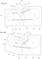
- FIGS. 4A-5B show the crop unloader system with certain parts removed to show underlying parts in more detail.
- FIGS. 5A and 5B show the same, but with the parts removed from FIGS. 4A and 4B in place.
- the crop unloader system also includes a tensioning assembly that is configured to maintain tension in the endless flexible drive 326 throughout the range of motion ⁇ .
- the tensioning assembly generally includes a tensioner link 400, a control link 402 and an idler wheel 404.
- the tensioner link 400 is pivotally connected to the elevator frame 300 at a first tensioner pivot 406, and the control link 402 is pivotally connected to the boom frame 318 at a second tensioner pivot 408.
- the control link 402 is pivotally connected to the tensioner link 400 at a third tensioner pivot 410.
- the tensioner link 400 and control link 402 preferably are rigid links (i.e., their lengths between pivots remain fixed during use), but they may include means to adjust their overall length during adjustment or maintenance.
- the first, second and third tensioner pivots 406, 408, 410 may comprise any rotatable joint (e.g., pins or the like), and they are all rotatable about respective rotation axes that are generally parallel both to each other, and to the boom pivot axis 324.
- the first, second and third tensioner pivots 406, 408, 410 and boom pivot axis 324 are also spaced from each other in directions perpendicular to their respective rotation axes (i.e., they are not collinear).
- a four-bar linkage is created by: the portion of the elevator frame between the boom pivot axis 324 and the first tensioner pivot 406; the portion of the boom frame 318 between the boom pivot axis 324 and the second tensioner pivot 308; the tensioner link 400; and the control link 402.
- tensioner link 400 and control link 402 may be reversed, with the tensioner link 400 being connected to the boom frame 318 at the first tensioner pivot 406, and the control link 402 being connected to the elevator frame 300 at the second tensioner pivot 408.
- the idler wheel 404 is connected to the tensioner link 400 and configured to generate a tension load on the endless flexible drive 326.
- the idler wheel 404 may be fixed directly to the tensioner link 400, such as by being pinned to the tensioner link on a pivot, in which case the tension on the endless flexible drive 326 may be set by adjusting the length of one or both of the tensioner link 400 and the control link 402.
- the idler wheel 404 is mounted on the tensioner link 400 such that the position of the idler wheel 404 relative to the tensioner link 400 can be adjusted.
- the idler wheel 404 is connected to the tensioner link 400 by an idler arm 412 and a tensioning screw 414.
- the idler arm 412 is pivotally connected at one end to the tensioner link 400 (e.g., by mounting the idler arm 412 on the first tensioner pivot 406, or at another location along the tensioner link 400), and pivotally connected to the idler wheel 404 at the other end by a idler wheel pivot 416 (see FIG. 5A ) to allow free rotation of the idler wheel 404 relative to the idler arm 412.
- the tensioning screw 414 is attached between the tensioner link 400 and the idler arm, at locations offset from the pivotal connection of the idler arm 412 to the tensioner link 400.
- a three-bar linkage is formed by the idler arm 412, tensioner link 400 and tensioning screw 414.
- the angular position of the idler arm 412 relative to the tensioner link 400-and thus the position of the idler wheel 404 relative to the tensioner link 400- is changed by adjusting the length of the tensioning screw 414. Such adjustment alters the tension preload on the endless flexible drive 326.
- the tensioning screw 414 may comprise any adjustable-length link, such as a threaded rod that is secured by a clevis to the idler arm 412, and to the tensioner link by threaded nuts.
- the tensioning screw 414 may comprise a turnbuckle that is pivotally connected at each end to the idler arm 412 and provided with a central cuff that can be rotated to alter the overall length.
- Other embodiments may use actively adjustable mechanisms (e.g., pneumatic or hydraulic telescoping connectors) or other mechanisms.
- the tensioning screw 414 also may be replaced by a spring or other resilient member that biases the idler wheel 404 against the endless flexible drive 326, but does not necessarily fix the position of the idler wheel 404 relative to the tensioner link 400.
- Other alternatives and variations will be apparent to persons of ordinary skill in the art in view of the present disclosure.
- the positions and dimensions of the various parts can be selected to maintain the desired tension load on the endless flexible drive 326 (i.e., keep the tension load within a range of desired or acceptable values) throughout the entire range of motion ⁇ of the boom frame 318 relative to the elevator frame 300.
- Variables that affect the tension as a function of angular position include, for example: the relative positions of the drive output axis 308, unloader drive input axis 322, boom pivot axis 324, and first, second and third tensioner pivots 406, 408, 410; the diameters of the elevator drive output 306, unloader drive input 320, and idler wheel 404; and the position of the idler wheel rotation axis relative to the tensioner link 400.
- 4A (which is illustrated to scale) has the following relative dimensions, with the diameter D1 of the elevator drive output 306 being selected as the unit value: Description Reference Sign Dimension Diameter of 306 D1 1.000 Diameter of 320 D2 0.682 Diameter of 404 D3 0.477 Distance from 308 to 324 L1 1.432 Distance from 322 to 324 L2 1.045 Distance from 308 to 406 L3 0.704 Distance from 322 to 408 L4 0.477 Distance from 406 to 410 L5 0.818 Distance from 408 to 410 L6 0.590 Table 1
- the idler wheel 404 rotation axis is essentially collinear with the third tensioner pivot 410, and so there is no need to take into consideration the idler wheel's position relative to the tensioner link 400. However, if the idler wheel 404 is displaced from this position, it's effect on the tension as a function of angular position can be determined using conventional geometric principles.
- first tensioner pivot 406, second tensioner pivot 408 and third tensioner pivot 410 are arranged such that the linkage formed by the tensioner link 400 and the control link 402 cannot invert as the boom assembly 118 moves through the range of motion ⁇ relative to the elevator assembly 116. If such inversion were to happen, the idler wheel 404 could travel opposite to the intended direction.
- the third tensioner pivot 410 is positioned such that it remains on one side of a line L intersecting the first tensioner pivot 406 and the second tensioner pivot 408, throughout the range of motion of the boom frame 318 relative to the elevator frame 300. In the case of FIGS.
- the third tensioner pivot 410 remains between the boom pivot axis 324 and the line L intersecting the first tensioner pivot 406 and the second tensioner pivot 408, throughout the range of motion ⁇ of the boom frame 318 relative to the elevator frame 300.
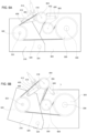
- FIGS. 6A and 6B show another embodiment, in which the tensioning assembly has been reversed and inverted.
- the parts are generally the same as those described in the embodiment of FIGS. 3-5B , so only the differences are discussed herein.
- the tensioning assembly is reversed by locating the first tensioner pivot 406 on the boom frame 318, and the second tensioner pivot 408 on the elevator frame 300.
- the tensioning assembly is inverted by positioning the third tensioner pivot 410 such that the line L intersecting the first tensioner pivot 406 and the second tensioner pivot 408 remains between the third tensioner pivot 410 and the boom pivot axis 324, throughout the range of motion ⁇ of the boom frame 318 relative to the elevator frame 300.
- the tensioning assembly also may include one or more additional idler wheels 600 rotatably fixed to the elevator frame 300 and/or boom frame 318, which help maintain the endless flexible drive 326 in a favorable relationship relative to the elevator drive output 306 and the unloader drive input 320 (e.g., such that the endless flexible drive 326 wraps around a greater portion of the elevator drive output 306 or the unloader drive input 320 to improve torque transfer).
- additional idler wheels 600 rotatably fixed to the elevator frame 300 and/or boom frame 318, which help maintain the endless flexible drive 326 in a favorable relationship relative to the elevator drive output 306 and the unloader drive input 320 (e.g., such that the endless flexible drive 326 wraps around a greater portion of the elevator drive output 306 or the unloader drive input 320 to improve torque transfer).
- FIG. 7 illustrates internal operating parts of a crop unloader system.
- a grain elevator is shown in the form of an endless flexible drive 700 (belt, chain, etc.) having paddles 702 extending from it.
- the endless flexible drive 700 wraps around the elevator drive 302, with the paddles 702 facing outward.
- Operating the elevator drive 302 causes the endless flexible drive 700 and paddles 702 to move, thus carrying crop material upwards and delivering it from the elevator assembly 116 to the boom assembly 118.
- the unloader conveyor belt 124 is driven by a belt drive 704, which is driven by an unloader drive 706 that transmits power to the belt drive 704 via a chain or belt 708, or some other form of power transmission (e.g., gears).
- the unloader drive 706 is operatively connected to the unloader drive input 320 (not shown), such as by being mounted to rotate with the unloader drive input 320 about the unloader drive input axis 322. Power is provided from the elevator drive 302 to the unloader drive input 320 via mechanisms such as explained above. Other embodiments may have other arrangements of internal operating parts.
- the belt drive 704 may be mounted to rotate about with the unloader drive input 320 about the unloader drive input axis 322.
- Other alternatives and variations will be apparent to persons of ordinary skill in the art in view of the present disclosure.
Landscapes
- Life Sciences & Earth Sciences (AREA)
- Environmental Sciences (AREA)
- Engineering & Computer Science (AREA)
- Mechanical Engineering (AREA)
- Ship Loading And Unloading (AREA)
Claims (13)
- Système de déchargement de matériau récolté comprenant :- un ensemble élévateur (116) comprenant :∘ un châssis d'élévateur (300),∘ un entraînement d'élévateur (302) fixé au châssis d'élévateur,∘ un moteur d'entraînement d'élévateur (304) fixé au châssis d'élévateur et configuré pour faire fonctionner sélectivement l'entraînement d'élévateur, et∘ une sortie d'entraînement d'élévateur (306) fixée au châssis d'élévateur et configurée pour être entraînée autour d'un axe de sortie d'entraînement d'élévateur horizontal (308) par le moteur d'entraînement d'élévateur ;- un ensemble flèche (118) comprenant :∘ un châssis de flèche (318) raccordé au châssis d'élévateur au niveau d'un axe de pivotement de flèche (324) qui est parallèle à l'axe de sortie d'entraînement d'élévateur, le châssis de flèche pouvant pivoter autour de l'axe de pivotement de flèche par rapport au châssis d'élévateur selon toute une gamme de mouvements entre une première position angulaire et une seconde position angulaire, et∘ une entrée d'entraînement de déchargeur (320) fixée au châssis de flèche et configurée pour pivoter autour d'un axe d'entrée d'entraînement de déchargeur (322) ;- un entraînement flexible sans fin (326) raccordé de manière fonctionnelle entre la sortie d'entraînement d'élévateur et l'entrée d'entraînement de déchargeur ;- un ensemble tendeur comprenant :∘ une biellette de tendeur (400) raccordée de manière pivotante à l'un parmi le châssis d'élévateur et le châssis de flèche au niveau d'un premier pivot de tendeur (406, 408),∘ une biellette de commande (402) raccordée de manière pivotante à l'autre parmi le châssis d'élévateur et le châssis de flèche au niveau d'un deuxième pivot de tendeur (406, 408), et raccordée de manière pivotante à la biellette de tendeur au niveau d'un troisième pivot de tendeur (410), le troisième pivot de tendeur étant espacé du premier pivot de tendeur et du deuxième pivot de tendeur,∘ une roue folle (404) raccordée fonctionnellement à la biellette de tendeur et configurée pour générer une charge de tension au niveau de l'entraînement flexible sans fin,caractérisé en ce que l'ensemble tendeur est configuré pour maintenir la charge de tension au niveau de l'entraînement flexible sans fin dans une plage prédéterminée, dans toute ladite gamme de mouvements du châssis de flèche par rapport au châssis d'élévateur, et dans lequel ladite charge de tension est maintenue par la combinaison suivante de caractéristiques :- la roue folle est fonctionnellement raccordée à la biellette de tendeur par un bras de renvoi (412), le bras de renvoi étant raccordé de manière pivotante au niveau d'une première extrémité à la biellette de tendeur, et raccordé de manière pivotante au niveau d'une seconde extrémité à la roue folle,- l'ensemble tendeur comprend en outre l'un des éléments suivants :∘ une vis de tension (414)∘ un raccordement télescopique pneumatique ou hydraulique,∘ un élément souple, comme un ressort,fixé entre le bras de renvoi et la biellette de tendeur et configuré pour contrôler une position de la roue folle par rapport à la biellette de tendeur.
- Le système de déchargement de matériau récolté selon la revendication 1, dans lequel l'ensemble élévateur comprend en outre un élévateur à grains (122) configuré pour être entraîné par l'entraînement d'élévateur, l'élévateur à grains comprenant de préférence une pluralité de palettes (702) montées sur une bande transporteuse de palettes sans fin (700) ou sur vis sans fin.
- Le système de déchargement de matériau récolté selon l'une quelconque des revendications précédentes, dans lequel le châssis d'élévateur comprend un coude en forme de tube (310) configuré pour diriger le matériau récolté de l'ensemble élévateur vers l'ensemble flèche.
- Le système de déchargement de matériau récolté selon l'une quelconque des revendications précédentes, dans lequel le châssis d'élévateur est configuré pour pouvoir pivoter autour d'un axe d'élévateur vertical qui est perpendiculaire à l'axe de sortie d'entraînement d'élévateur.
- Le système de déchargement de matériau récolté selon l'une quelconque des revendications précédentes, dans lequel chacune parmi la sortie d'entraînement d'élévateur et l'entrée d'entraînement de déchargeur comprend une poulie respective ou un pignon respectif.
- Le système de déchargement de matériau récolté selon l'une quelconque des revendications précédentes, dans lequel l'ensemble élévateur comprend en outre une bande transporteuse de déchargement (124) raccordée fonctionnellement à l'entrée d'entraînement de déchargeur.
- Le système de déchargement de matériau récolté selon la revendication 6, dans lequel l'ensemble élévateur comprend en outre une goulotte de bande de déchargement (126) enveloppant la bande transporteuse de déchargement.
- Le système de déchargement de matériau récolté selon l'une quelconque des revendications précédentes, dans lequel l'entraînement flexible sans fin comprend une bande ou une chaîne.
- Le système de déchargement de matériau récolté selon la revendication 1, dans lequel le bras de renvoi est raccordé de manière pivotante au niveau de la première extrémité à la biellette de tendeur du premier pivot de tendeur.
- Le système de déchargement de matériau récolté selon l'une quelconque des revendications précédentes, dans lequel le troisième pivot de tendeur est situé sur un côté d'une ligne (L) croisant le premier pivot de tendeur et le deuxième pivot de tendeur pour toute la gamme de mouvements du châssis de flèche par rapport au châssis d'élévateur.
- Le système de déchargement de matériau récolté selon la revendication 10, dans lequel le troisième pivot de tendeur est situé entre la ligne et l'axe de pivotement de flèche pour toute la gamme de mouvements du châssis de flèche par rapport au châssis d'élévateur.
- Le système de déchargement de matériau récolté selon la revendication 10, dans lequel la ligne est située entre le troisième pivot de tendeur et l'axe de pivotement de flèche pour toute la gamme de mouvements du châssis de flèche par rapport au châssis d'élévateur.
- Une moissonneuse-batteuse agricole (100) comprenant :un châssis (102) configuré pour se déplacer sur une surface ;un système de battage et de séparation (108) fixé au châssis ;une trémie (112) située sur le châssis et configurée pour retenir le matériau récolté à l'intérieur ; etun système de déchargement de matériau récolté selon l'une quelconque des revendications précédentes.
Applications Claiming Priority (1)
| Application Number | Priority Date | Filing Date | Title |
|---|---|---|---|
| US17/553,220 US12234099B2 (en) | 2021-12-16 | 2021-12-16 | Crop unloader drive with tensioner |
Publications (2)
| Publication Number | Publication Date |
|---|---|
| EP4197311A1 EP4197311A1 (fr) | 2023-06-21 |
| EP4197311B1 true EP4197311B1 (fr) | 2024-08-14 |
Family
ID=84519500
Family Applications (1)
| Application Number | Title | Priority Date | Filing Date |
|---|---|---|---|
| EP22213064.3A Active EP4197311B1 (fr) | 2021-12-16 | 2022-12-13 | Entraînement de décharge de récolte avec tendeur |
Country Status (2)
| Country | Link |
|---|---|
| US (1) | US12234099B2 (fr) |
| EP (1) | EP4197311B1 (fr) |
Family Cites Families (28)
| Publication number | Priority date | Publication date | Assignee | Title |
|---|---|---|---|---|
| USRE24920E (en) * | 1961-01-03 | Material handling system | ||
| US1374728A (en) * | 1919-03-27 | 1921-04-12 | Leo J Geier | Elevator |
| US2541984A (en) * | 1948-05-04 | 1951-02-20 | Hi Way Implement Company | Grain unloading attachment for combines |
| US2724516A (en) * | 1950-04-13 | 1955-11-22 | Emrich A Weishaar | Wagon loading attachment for combines |
| US3630009A (en) * | 1969-10-30 | 1971-12-28 | Massey Ferguson Ind Ltd | Self-propelled sweet corn harvester |
| US3863783A (en) * | 1971-12-16 | 1975-02-04 | Symons Corp | Distributing conveyor system for a rotary concrete mixing or other truck |
| US4372440A (en) * | 1980-12-22 | 1983-02-08 | The Boeing Company | End shaft mount for conveyor |
| GB2096083A (en) | 1981-04-08 | 1982-10-13 | Nat Res Dev | Transfer conveying assembly |
| US5100281A (en) | 1989-07-26 | 1992-03-31 | J. & M. Manufacturing Co., Inc. | Grain wagon with unload mechanism |
| US5108249A (en) * | 1990-07-23 | 1992-04-28 | Kinze Manufacturing, Inc. | Gravity fed, chain conveyer for grain cart |
| US5359838A (en) | 1994-01-27 | 1994-11-01 | Madsen William H | Apparatus for controlling the direction of a crop discharge spout on agricultural machinery with respect to an associated collector |
| US5584640A (en) * | 1994-04-20 | 1996-12-17 | Eaton Corporation | Grain tank unloading auger drive means |
| US5518453A (en) * | 1994-06-23 | 1996-05-21 | Case Corporation | Unloading control system for an agricultural combine |
| CA2240869C (fr) | 1998-06-17 | 2005-08-23 | Bourgault Industries Ltd. | Entrainement de chariots a cereales |
| DE10021664B4 (de) | 2000-05-04 | 2004-05-06 | Maschinenfabrik Bernard Krone Gmbh | Erntemaschine, insbesondere selbstfahrender Feldhäcksler |
| DE10141702A1 (de) | 2001-08-25 | 2003-03-06 | Deere & Co | Einrichtung zum Antrieb einer Austrageinrichtung einer landwirtschaftlichen Erntemaschine |
| US6743093B1 (en) | 2002-12-04 | 2004-06-01 | Deere & Co. | Auxiliary drive for combine augers for cleanout |
| US7367881B2 (en) | 2006-02-10 | 2008-05-06 | Agco Corporation | High capacity combine grain bin unload system |
| US9254773B2 (en) * | 2008-05-22 | 2016-02-09 | Cnh Industrial America Llc | Adaptive rate control for feeding grain to a grain unloader conveyor |
| US8616364B2 (en) * | 2011-10-11 | 2013-12-31 | Cnh America Llc | Harvester crop delivery system |
| DE102012007637A1 (de) * | 2012-04-18 | 2013-10-24 | Claas Selbstfahrende Erntemaschinen Gmbh | Vorrichtung zum Spannen eines Zugmittels einer Fördereinrichtung |
| BR102013026992B1 (pt) | 2012-10-19 | 2020-01-07 | Cnh Industrial America Llc | Ceifadeira agrícola, sistema de transmissão de força e método de manter uma pressão sobre uma ligação flexível de um sistema de transmissão de força |
| GB201223549D0 (en) * | 2012-12-21 | 2013-02-13 | Laverda Spa | Constant tensioning means for rotary motion transfer apparatus |
| US9516817B2 (en) * | 2015-03-26 | 2016-12-13 | Deere & Company | Grain-moving arrangement for an agricultural combine |
| BE1023983A9 (nl) * | 2016-03-23 | 2017-10-19 | Cnh Ind Belgium Nv | Geïntegreerd omkeersysteem met riemkoppeling |
| CN106717489A (zh) * | 2017-01-06 | 2017-05-31 | 河南瑞创通用机械制造有限公司 | 一种谷物联合收获机自动高位卸粮装置及联合收割机 |
| JP6858651B2 (ja) | 2017-06-06 | 2021-04-14 | 株式会社クボタ | コンバイン |
| BR102018003979B1 (pt) * | 2018-02-28 | 2022-08-09 | Cnh Industrial Brasil Ltda | Conjunto elevador de uma máquina de colher e máquina colheitadeira |
-
2021
- 2021-12-16 US US17/553,220 patent/US12234099B2/en active Active
-
2022
- 2022-12-13 EP EP22213064.3A patent/EP4197311B1/fr active Active
Also Published As
| Publication number | Publication date |
|---|---|
| EP4197311A1 (fr) | 2023-06-21 |
| US20230192411A1 (en) | 2023-06-22 |
| US12234099B2 (en) | 2025-02-25 |
Similar Documents
| Publication | Publication Date | Title |
|---|---|---|
| US5184715A (en) | Mechanical drive for dual conveyor system | |
| US8272494B2 (en) | Conveyor assembly | |
| US3229827A (en) | Material handling apparatus | |
| KR101974222B1 (ko) | 작업기의 크롤러 주행 장치 | |
| US9944211B2 (en) | Seed carrier with pivoting conveyor | |
| EP4197311B1 (fr) | Entraînement de décharge de récolte avec tendeur | |
| US2601618A (en) | Unloading assembly for wagon boxes | |
| US5094334A (en) | Mechanically driven auger system | |
| KR100855667B1 (ko) | 볏짚자동이송장치 | |
| US2623624A (en) | Loading conveyer for grain and other materials | |
| US1374728A (en) | Elevator | |
| US3731569A (en) | Harvesting machine | |
| BR102022025146A2 (pt) | Sistema de descarregamento de colheita e colheitadeira combinada | |
| JP3959101B2 (ja) | コンバイン | |
| AU2011342278B2 (en) | Auger conveyor with extendible swing auger assembly | |
| JP3841745B2 (ja) | コンバイン | |
| CN103260392A (zh) | 联合收割机 | |
| CN219468778U (zh) | 一种放粮位置可调的自卸式放粮机构 | |
| US12426538B2 (en) | Swing-out spreader for agricultural combines | |
| CA1158193A (fr) | Accouplement de semoirs | |
| US2778511A (en) | Wagon box to elevator power transfer unit | |
| JP3821770B2 (ja) | コンバイン | |
| JPH0851848A (ja) | コンバインの主伝動装置 | |
| US601582A (en) | Portable grain-elevator | |
| US271404A (en) | Berger |
Legal Events
| Date | Code | Title | Description |
|---|---|---|---|
| PUAI | Public reference made under article 153(3) epc to a published international application that has entered the european phase |
Free format text: ORIGINAL CODE: 0009012 |
|
| STAA | Information on the status of an ep patent application or granted ep patent |
Free format text: STATUS: THE APPLICATION HAS BEEN PUBLISHED |
|
| AK | Designated contracting states |
Kind code of ref document: A1 Designated state(s): AL AT BE BG CH CY CZ DE DK EE ES FI FR GB GR HR HU IE IS IT LI LT LU LV MC ME MK MT NL NO PL PT RO RS SE SI SK SM TR |
|
| STAA | Information on the status of an ep patent application or granted ep patent |
Free format text: STATUS: REQUEST FOR EXAMINATION WAS MADE |
|
| 17P | Request for examination filed |
Effective date: 20231221 |
|
| RBV | Designated contracting states (corrected) |
Designated state(s): AL AT BE BG CH CY CZ DE DK EE ES FI FR GB GR HR HU IE IS IT LI LT LU LV MC ME MK MT NL NO PL PT RO RS SE SI SK SM TR |
|
| GRAP | Despatch of communication of intention to grant a patent |
Free format text: ORIGINAL CODE: EPIDOSNIGR1 |
|
| STAA | Information on the status of an ep patent application or granted ep patent |
Free format text: STATUS: GRANT OF PATENT IS INTENDED |
|
| RIC1 | Information provided on ipc code assigned before grant |
Ipc: A01D 43/08 20060101ALI20240229BHEP Ipc: A01D 17/02 20060101ALI20240229BHEP Ipc: A01D 61/00 20060101ALI20240229BHEP Ipc: A01F 12/46 20060101ALI20240229BHEP Ipc: A01D 41/12 20060101AFI20240229BHEP |
|
| INTG | Intention to grant announced |
Effective date: 20240319 |
|
| GRAS | Grant fee paid |
Free format text: ORIGINAL CODE: EPIDOSNIGR3 |
|
| GRAA | (expected) grant |
Free format text: ORIGINAL CODE: 0009210 |
|
| STAA | Information on the status of an ep patent application or granted ep patent |
Free format text: STATUS: THE PATENT HAS BEEN GRANTED |
|
| AK | Designated contracting states |
Kind code of ref document: B1 Designated state(s): AL AT BE BG CH CY CZ DE DK EE ES FI FR GB GR HR HU IE IS IT LI LT LU LV MC ME MK MT NL NO PL PT RO RS SE SI SK SM TR |
|
| REG | Reference to a national code |
Ref country code: GB Ref legal event code: FG4D |
|
| REG | Reference to a national code |
Ref country code: CH Ref legal event code: EP |
|
| REG | Reference to a national code |
Ref country code: DE Ref legal event code: R096 Ref document number: 602022005340 Country of ref document: DE |
|
| REG | Reference to a national code |
Ref country code: IE Ref legal event code: FG4D |
|
| REG | Reference to a national code |
Ref country code: LT Ref legal event code: MG9D |
|
| REG | Reference to a national code |
Ref country code: NL Ref legal event code: MP Effective date: 20240814 |
|
| PG25 | Lapsed in a contracting state [announced via postgrant information from national office to epo] |
Ref country code: NO Free format text: LAPSE BECAUSE OF FAILURE TO SUBMIT A TRANSLATION OF THE DESCRIPTION OR TO PAY THE FEE WITHIN THE PRESCRIBED TIME-LIMIT Effective date: 20241114 |
|
| REG | Reference to a national code |
Ref country code: AT Ref legal event code: MK05 Ref document number: 1712361 Country of ref document: AT Kind code of ref document: T Effective date: 20240814 |
|
| PG25 | Lapsed in a contracting state [announced via postgrant information from national office to epo] |
Ref country code: GR Free format text: LAPSE BECAUSE OF FAILURE TO SUBMIT A TRANSLATION OF THE DESCRIPTION OR TO PAY THE FEE WITHIN THE PRESCRIBED TIME-LIMIT Effective date: 20241115 Ref country code: NL Free format text: LAPSE BECAUSE OF FAILURE TO SUBMIT A TRANSLATION OF THE DESCRIPTION OR TO PAY THE FEE WITHIN THE PRESCRIBED TIME-LIMIT Effective date: 20240814 Ref country code: PL Free format text: LAPSE BECAUSE OF FAILURE TO SUBMIT A TRANSLATION OF THE DESCRIPTION OR TO PAY THE FEE WITHIN THE PRESCRIBED TIME-LIMIT Effective date: 20240814 Ref country code: FI Free format text: LAPSE BECAUSE OF FAILURE TO SUBMIT A TRANSLATION OF THE DESCRIPTION OR TO PAY THE FEE WITHIN THE PRESCRIBED TIME-LIMIT Effective date: 20240814 Ref country code: PT Free format text: LAPSE BECAUSE OF FAILURE TO SUBMIT A TRANSLATION OF THE DESCRIPTION OR TO PAY THE FEE WITHIN THE PRESCRIBED TIME-LIMIT Effective date: 20241216 |
|
| PG25 | Lapsed in a contracting state [announced via postgrant information from national office to epo] |
Ref country code: BG Free format text: LAPSE BECAUSE OF FAILURE TO SUBMIT A TRANSLATION OF THE DESCRIPTION OR TO PAY THE FEE WITHIN THE PRESCRIBED TIME-LIMIT Effective date: 20240814 |
|
| PG25 | Lapsed in a contracting state [announced via postgrant information from national office to epo] |
Ref country code: LV Free format text: LAPSE BECAUSE OF FAILURE TO SUBMIT A TRANSLATION OF THE DESCRIPTION OR TO PAY THE FEE WITHIN THE PRESCRIBED TIME-LIMIT Effective date: 20240814 |
|
| PG25 | Lapsed in a contracting state [announced via postgrant information from national office to epo] |
Ref country code: AT Free format text: LAPSE BECAUSE OF FAILURE TO SUBMIT A TRANSLATION OF THE DESCRIPTION OR TO PAY THE FEE WITHIN THE PRESCRIBED TIME-LIMIT Effective date: 20240814 Ref country code: IS Free format text: LAPSE BECAUSE OF FAILURE TO SUBMIT A TRANSLATION OF THE DESCRIPTION OR TO PAY THE FEE WITHIN THE PRESCRIBED TIME-LIMIT Effective date: 20241214 |
|
| PG25 | Lapsed in a contracting state [announced via postgrant information from national office to epo] |
Ref country code: HR Free format text: LAPSE BECAUSE OF FAILURE TO SUBMIT A TRANSLATION OF THE DESCRIPTION OR TO PAY THE FEE WITHIN THE PRESCRIBED TIME-LIMIT Effective date: 20240814 |
|
| PG25 | Lapsed in a contracting state [announced via postgrant information from national office to epo] |
Ref country code: RS Free format text: LAPSE BECAUSE OF FAILURE TO SUBMIT A TRANSLATION OF THE DESCRIPTION OR TO PAY THE FEE WITHIN THE PRESCRIBED TIME-LIMIT Effective date: 20241114 Ref country code: ES Free format text: LAPSE BECAUSE OF FAILURE TO SUBMIT A TRANSLATION OF THE DESCRIPTION OR TO PAY THE FEE WITHIN THE PRESCRIBED TIME-LIMIT Effective date: 20240814 |
|
| PG25 | Lapsed in a contracting state [announced via postgrant information from national office to epo] |
Ref country code: RS Free format text: LAPSE BECAUSE OF FAILURE TO SUBMIT A TRANSLATION OF THE DESCRIPTION OR TO PAY THE FEE WITHIN THE PRESCRIBED TIME-LIMIT Effective date: 20241114 Ref country code: PT Free format text: LAPSE BECAUSE OF FAILURE TO SUBMIT A TRANSLATION OF THE DESCRIPTION OR TO PAY THE FEE WITHIN THE PRESCRIBED TIME-LIMIT Effective date: 20241216 Ref country code: PL Free format text: LAPSE BECAUSE OF FAILURE TO SUBMIT A TRANSLATION OF THE DESCRIPTION OR TO PAY THE FEE WITHIN THE PRESCRIBED TIME-LIMIT Effective date: 20240814 Ref country code: NO Free format text: LAPSE BECAUSE OF FAILURE TO SUBMIT A TRANSLATION OF THE DESCRIPTION OR TO PAY THE FEE WITHIN THE PRESCRIBED TIME-LIMIT Effective date: 20241114 Ref country code: NL Free format text: LAPSE BECAUSE OF FAILURE TO SUBMIT A TRANSLATION OF THE DESCRIPTION OR TO PAY THE FEE WITHIN THE PRESCRIBED TIME-LIMIT Effective date: 20240814 Ref country code: LV Free format text: LAPSE BECAUSE OF FAILURE TO SUBMIT A TRANSLATION OF THE DESCRIPTION OR TO PAY THE FEE WITHIN THE PRESCRIBED TIME-LIMIT Effective date: 20240814 Ref country code: IS Free format text: LAPSE BECAUSE OF FAILURE TO SUBMIT A TRANSLATION OF THE DESCRIPTION OR TO PAY THE FEE WITHIN THE PRESCRIBED TIME-LIMIT Effective date: 20241214 Ref country code: HR Free format text: LAPSE BECAUSE OF FAILURE TO SUBMIT A TRANSLATION OF THE DESCRIPTION OR TO PAY THE FEE WITHIN THE PRESCRIBED TIME-LIMIT Effective date: 20240814 Ref country code: GR Free format text: LAPSE BECAUSE OF FAILURE TO SUBMIT A TRANSLATION OF THE DESCRIPTION OR TO PAY THE FEE WITHIN THE PRESCRIBED TIME-LIMIT Effective date: 20241115 Ref country code: FI Free format text: LAPSE BECAUSE OF FAILURE TO SUBMIT A TRANSLATION OF THE DESCRIPTION OR TO PAY THE FEE WITHIN THE PRESCRIBED TIME-LIMIT Effective date: 20240814 Ref country code: ES Free format text: LAPSE BECAUSE OF FAILURE TO SUBMIT A TRANSLATION OF THE DESCRIPTION OR TO PAY THE FEE WITHIN THE PRESCRIBED TIME-LIMIT Effective date: 20240814 Ref country code: BG Free format text: LAPSE BECAUSE OF FAILURE TO SUBMIT A TRANSLATION OF THE DESCRIPTION OR TO PAY THE FEE WITHIN THE PRESCRIBED TIME-LIMIT Effective date: 20240814 Ref country code: AT Free format text: LAPSE BECAUSE OF FAILURE TO SUBMIT A TRANSLATION OF THE DESCRIPTION OR TO PAY THE FEE WITHIN THE PRESCRIBED TIME-LIMIT Effective date: 20240814 |
|
| PG25 | Lapsed in a contracting state [announced via postgrant information from national office to epo] |
Ref country code: RO Free format text: LAPSE BECAUSE OF FAILURE TO SUBMIT A TRANSLATION OF THE DESCRIPTION OR TO PAY THE FEE WITHIN THE PRESCRIBED TIME-LIMIT Effective date: 20240814 Ref country code: SM Free format text: LAPSE BECAUSE OF FAILURE TO SUBMIT A TRANSLATION OF THE DESCRIPTION OR TO PAY THE FEE WITHIN THE PRESCRIBED TIME-LIMIT Effective date: 20240814 Ref country code: DK Free format text: LAPSE BECAUSE OF FAILURE TO SUBMIT A TRANSLATION OF THE DESCRIPTION OR TO PAY THE FEE WITHIN THE PRESCRIBED TIME-LIMIT Effective date: 20240814 |
|
| PG25 | Lapsed in a contracting state [announced via postgrant information from national office to epo] |
Ref country code: EE Free format text: LAPSE BECAUSE OF FAILURE TO SUBMIT A TRANSLATION OF THE DESCRIPTION OR TO PAY THE FEE WITHIN THE PRESCRIBED TIME-LIMIT Effective date: 20240814 |
|
| PG25 | Lapsed in a contracting state [announced via postgrant information from national office to epo] |
Ref country code: CZ Free format text: LAPSE BECAUSE OF FAILURE TO SUBMIT A TRANSLATION OF THE DESCRIPTION OR TO PAY THE FEE WITHIN THE PRESCRIBED TIME-LIMIT Effective date: 20240814 |
|
| PG25 | Lapsed in a contracting state [announced via postgrant information from national office to epo] |
Ref country code: IT Free format text: LAPSE BECAUSE OF FAILURE TO SUBMIT A TRANSLATION OF THE DESCRIPTION OR TO PAY THE FEE WITHIN THE PRESCRIBED TIME-LIMIT Effective date: 20240814 Ref country code: SK Free format text: LAPSE BECAUSE OF FAILURE TO SUBMIT A TRANSLATION OF THE DESCRIPTION OR TO PAY THE FEE WITHIN THE PRESCRIBED TIME-LIMIT Effective date: 20240814 |
|
| REG | Reference to a national code |
Ref country code: DE Ref legal event code: R097 Ref document number: 602022005340 Country of ref document: DE |
|
| PLBE | No opposition filed within time limit |
Free format text: ORIGINAL CODE: 0009261 |
|
| STAA | Information on the status of an ep patent application or granted ep patent |
Free format text: STATUS: NO OPPOSITION FILED WITHIN TIME LIMIT |
|
| PG25 | Lapsed in a contracting state [announced via postgrant information from national office to epo] |
Ref country code: MC Free format text: LAPSE BECAUSE OF FAILURE TO SUBMIT A TRANSLATION OF THE DESCRIPTION OR TO PAY THE FEE WITHIN THE PRESCRIBED TIME-LIMIT Effective date: 20240814 |
|
| 26N | No opposition filed |
Effective date: 20250515 |
|
| PG25 | Lapsed in a contracting state [announced via postgrant information from national office to epo] |
Ref country code: LU Free format text: LAPSE BECAUSE OF NON-PAYMENT OF DUE FEES Effective date: 20241213 |
|
| PG25 | Lapsed in a contracting state [announced via postgrant information from national office to epo] |
Ref country code: SE Free format text: LAPSE BECAUSE OF FAILURE TO SUBMIT A TRANSLATION OF THE DESCRIPTION OR TO PAY THE FEE WITHIN THE PRESCRIBED TIME-LIMIT Effective date: 20240814 |
|
| REG | Reference to a national code |
Ref country code: BE Ref legal event code: MM Effective date: 20241231 |
|
| PG25 | Lapsed in a contracting state [announced via postgrant information from national office to epo] |
Ref country code: BE Free format text: LAPSE BECAUSE OF NON-PAYMENT OF DUE FEES Effective date: 20241231 |
|
| PG25 | Lapsed in a contracting state [announced via postgrant information from national office to epo] |
Ref country code: IE Free format text: LAPSE BECAUSE OF NON-PAYMENT OF DUE FEES Effective date: 20241213 |
|
| PGFP | Annual fee paid to national office [announced via postgrant information from national office to epo] |
Ref country code: FR Payment date: 20251223 Year of fee payment: 4 |
|
| PGFP | Annual fee paid to national office [announced via postgrant information from national office to epo] |
Ref country code: DE Payment date: 20251229 Year of fee payment: 4 |