EP4197408B1 - Dispositif de cuisson avec protection anti-éclaboussure - Google Patents
Dispositif de cuisson avec protection anti-éclaboussure Download PDFInfo
- Publication number
- EP4197408B1 EP4197408B1 EP21215385.2A EP21215385A EP4197408B1 EP 4197408 B1 EP4197408 B1 EP 4197408B1 EP 21215385 A EP21215385 A EP 21215385A EP 4197408 B1 EP4197408 B1 EP 4197408B1
- Authority
- EP
- European Patent Office
- Prior art keywords
- cooking device
- cooking
- splash guard
- controlling unit
- cooking plate
- Prior art date
- Legal status (The legal status is an assumption and is not a legal conclusion. Google has not performed a legal analysis and makes no representation as to the accuracy of the status listed.)
- Active
Links
Images



Classifications
-
- A—HUMAN NECESSITIES
- A47—FURNITURE; DOMESTIC ARTICLES OR APPLIANCES; COFFEE MILLS; SPICE MILLS; SUCTION CLEANERS IN GENERAL
- A47J—KITCHEN EQUIPMENT; COFFEE MILLS; SPICE MILLS; APPARATUS FOR MAKING BEVERAGES
- A47J37/00—Baking; Roasting; Grilling; Frying
- A47J37/06—Roasters; Grills; Sandwich grills
- A47J37/067—Horizontally disposed broiling griddles
- A47J37/0676—Horizontally disposed broiling griddles electrically heated
Definitions
- the present invention relates to a cooking device and, more particularly, to an electrical cooking device with limited heating power, comprising a low heat spreading zone as well as a removable and repositionable anti-splash guard.
- a griddle is used for cooking, baking, or roasting meats, bread, and vegetables. It has an upper surface, wherein the food is placed, heated evenly by heat transfer from the lower surface.
- the surface is generally a flat metal surface that can be heated by various heating sources such as gas or electricity.
- An anti-splash guard is a device partially or fully surrounding the griddle to prevent hot liquids or greases from spitting out of the cooking surface, which often happens when food is cooked at elevated temperatures. For user's convenience, stopping or at least reducing the splattering of hot liquids in the surrounding of the griddle reduces the cleaning time after use. Nevertheless, such anti-splash guards increase the height of the griddle, making them bulkier for limited storage space in a kitchen.
- Griddles are usually only used in barbequing events, which happens occasionally. Therefore, their storage always requires a significant space, which is not convenient for many users, especially if their storage spaces are limited. Accordingly, there is a need to reduce the volume of griddles with splash guard.
- the cooking device has limited heating power to reduce splashes.
- the maximal power should not exceed 2200 watts, preferably 2000 watts, most preferably 1800 watts.
- the griddle comprises a first heat spreading zone with low power (keep warm zone) and a second heat spreading zone with high power (cooking zone) to achieve these limitations while keeping a sufficient cooking capacity.
- Utility model CN204379008U describes an electric roaster device provided with three detachable windshields connected to two flexible connecting sleeves to make it convenient for storage.
- assembling and disassembling these windshields before and after every use might damage their interlocking and make it difficult for the user to use them.
- solving the storage issue by providing multiple parts can make them easy to lose. Therefore, a solution to overcome these challenges more conveniently for the user is needed.
- the present invention discloses a cooking device comprising:
- the invention includes at least one or an appropriate combination of the following features:
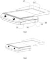
- a cooking device 1 of the present invention is shown.
- the cooking device 1 has a cooking plate 3, a controlling unit 4, and a removable and repositionable anti-splash guard 2.
- This kind of cooking device 1 is made for outdoor and indoor use and configured to be readily movable by a user such that the cooking device 1 is portable.
- the cooking plate 3 is installed horizontally and on top of the controlling unit 4. It allows the user to directly lay down the food to be cooked.
- the cooking plate 3 may define a rectangular or square shape and can have various dimensions.
- the cooking device 1 includes a controlling unit 4 having two control knobs 6 and 6' equipped with light indicators 7 and 7' that allow the user to control each of the two heating zones separately.
- a zoom-in illustration of the control knob 6 with the light indicator 7 is shown in FIG. 2 .
- the cooking device 1 may include a front side 8, a rear side 9, a right side 10, a left side 11, an upper side 12 and a bottom side 13.
- the front side 8 is the side where the user stands for operating the cooking device 1.
- the rear side 9 is opposite the front side 8 of the cooking device 1 and comprises the integrated cord storage 14 (see FIG. 3 ).
- the right side 10 is on the user's right side when standing in front of the front side 8 and is opposite the left side 11.
- the upper side 12 is opposite the bottom side 13 of the cooking device 1.
- the bottom side 13 of the cooking device 1 includes attachable or detachable legs but may also include anti-slip pads or surfaces, breakable wheels or rollers, or any stabilising system.
- the bottom side 13 may include height adjustable legs or pads for better stability of the cooking device 1 and for defining an inclination so that the greases and liquids released from food can more easily descend to the grease drip tray 15 shown in FIG. 3 .
- the cooking device 1 includes a removable and repositionable anti-splash guard 2 that is selectively positioned on the working position and housed by its edges 17, 17', and 17" (see FIG. 7 ) in the side groove 16 (See FIG. 5 ) between the cooking plate 3 and the controlling unit 4.
- the anti-splash guard 2 has three vertical sidewalls rising toward the rear side 9 of the cooking device 1 and closely surrounding the cooking plate 3.
- the sidewalls of the anti-splash guard 2 are approximately 10cm high on the rear wall and start with a height of approximately 2cm on the left and right side, until they reach the exact height of the rear wall.
- the anti-splash guard 2 entirely slides back through the side groove 16 between the cooking plate 3 and the controlling unit 4 and can be removed. After use, the anti-splash guard 2 can be flipped upside down and slid ahead through said side groove 16 to be in the storing position (See FIG. 9 ). In this way, the user may decide to use various positions of the anti-splash guard 2 based on the desired application.
- the anti-splash guard 2 prevents the liquid released from food items during cooking from splattering from the cooking plate 3 to the surrounding area of the cooking device 1. Accordingly, the splattering of liquids on the surrounding areas of the cooking device 1 is substantially reduced or eliminated.
- the anti-splash guard 2 is easily removable from the cooking device 1 through the side groove 16 and repositionable by flipping it upside down and sliding it onto the same side groove 16. In addition, flipping the sidewalls into the cooking device 1 will save significant space.
- the anti-splash guard 2 is made from metal and has a non-stick coating to make the cleaning action easier for the user.
- the working position of the anti-splash guard 2 is defined when the sidewalls are surrounding the cooking plate 3 rising towards the rear side of the cooking device 1. As shown in FIGS. 1 , 3, and 4 , the anti-splash guard 2 is positioned by sliding the edges 17, 17', and 17" from the rear side 9 to the front side 8 of the cooking device 1 through the sides groove 16 formed by the vertical gap between the controlling unit 4 and the cooking plate 3.
- the storing position of the anti-splash guard 2 is defined when the sidewalls surrounding the cooking plate 1 falls towards the rear side 9 of the cooking device 1.
- the anti-splash guard 2 is positioned by sliding the edges 17, 17', and 17" from the rear side 9 to the front side 8 of the cooking device 1 through the side groove 16 formed by the vertical gap between the controlling unit 4 and the cooking plate 3.
- the anti-splash guard 2 in the storing position is flipped upside down from the working position.
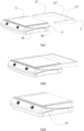
- FIGS. 1 , 5 , 6 , 7, 8, and 9 the steps for positioning the anti-splash guard 2 from the working position to the storing position are illustrated respectively.
- FIG. 1 shows the anti-splash guard 2 in working position.
- FIG. 5 shows the anti-splash guard 2 sliding back partially toward the rear side 9 of the cooking device 1 before its complete separation in FIG. 6 .
- the anti-splash guard 2 is flipped upside down and prepared to have its edges 17, 17', and 17" slid into the vertical side groove 16 positioned between the controlling unit 4 and the cooking plate 3 from the rear side 9 to the front side 8 of the cooking device 1, as shown in FIG. 7 .
- FIG. 8 is similar to the position shown in FIG. 5 , except that the anti-splash guard 2 is flipped upside down.
- FIG. 9 shows the end sliding position of the anti-splash guard 2, which represents the storing position.
- the sidewalls partially cover the sides of the controlling unit 4, reducing the necessary storage volume.
- the anti-splash guard 2 may be controlled by a release button 21.
- the release button 21 maintains a fixed position of the anti-splash guard 2 in both positions, namely the working position and the storing position.
- the release button 21 can also function to unlock the anti-splash guard 2 so that a user can slide and flip the anti-splash guard 2 from the working position to the storing position and vice versa.
- actuating the release button 21 unlocks the engagement of the edges 17, 17', and 17" of the anti-splash guard 2 with the side groove 16, thereby enabling a user to change the position of the anti-splash guard 2 from the working position to the storing position and vice versa.
- the release button 21 can also lock the engagement of the edges 17, 17', and 17" of the anti-splash guard 2 with the side groove 16, enabling the fixation of the anti-splash guard in the desired position.
- the upper side 12 of the cooking device 1 may include a cooking plate 3 with various heat spreading zones.
- a first heat spreading zone with low power and a second heat spreading zone with high power may be distributed in different ways depending on the user's need.
- the second heat spreading zone may define the cooking zone with a temperature up to around 300°C, preferably 260°C
- the first heat spreading zone may define the keep warm zone at a temperature lower than the temperature of the second heat spreading zone, to around 120°C and preferably 80°C.
- the main objective is to use the same mechanical structure and the same cooking plate for different geographical areas with different network voltages and available power limits.
- the cooking plate 3 is made with a material with a lower conductivity than aluminium, preferably stainless steel, which requires a lower power density to reach a minimum cooking temperature of more than 200°C.
- This power may be achieved by allocating all or part of the total surface of the cooking plate 3 without physical delimitation by using resistive heating elements having different geometries plated under the cooking plate 3, instead of inductive heating elements, taking advantage of the horizontal non-conductivity in the thickness of the cooking plate 3 to make the different zones coexist.
- the total heating power of the cooking device 1 does not exceed 2200 watts, preferably 2000 watts, more preferably 1800 watts.
- the first heat spreading zone with low power and a second heat spreading zone with high power may be separated horizontally or vertically, but one zone may also surround one another partially or entirely. In this manner, the user may decide to use various geographical distributions of the two heat spreading zones based on the desired application.
- FIG. 3 illustrates an integrated cord storage 14 located on the rear side 9 of the cooking device 1.
- the electrical cord 18 used to supply the cooking device 1 with the needed power might be wound around it, making it convenient for a user to store the electrical cord 18 after use or during the transport of the cooking device 1.
- the cooking device 1 includes a recessed handle 19 that allows a user to lift and transport the cooking device 1 easily and safely without being burnt or getting dirty.
- Another recessed area 19' is also present on the opposite side of the cooking device 1 shown in FIG. 4 .
- the right side 10 may also include a high height grease drip tray 15 that is removable and dishwasher safe.
- the grease drip tray 15 may have a rectangular shape and might have transparent sidewalls to allow a user to decide when it needs to be emptied from the collected liquids.
- the grease drip tray 15 is housed inside the controlling unit 4 and located below the opening channel (not shown) of the controlling unit 4, linked to the front grooved channel 20 located in the cooking plate 3. When greases and liquids are released from the cooked food, they fall into the front grooved channel 20, which has a longitudinal inclination toward the opening channel in the controlling unit 4. The greases and liquids pass via the front grooved channel 20 to the opening channel, dripping down in the grease drip tray 15.
Landscapes
- Engineering & Computer Science (AREA)
- Food Science & Technology (AREA)
- Baking, Grill, Roasting (AREA)
Claims (14)
- Dispositif de cuisson (1) comprenant :- une unité de commande (4) ;- une plaque de cuisson (3) sur laquelle sont directement déposés les aliments à cuire ;- une protection anti-éclaboussures (2) amovible et repositionnable comprenant deux positions, une position de travail entourant les zones de chauffe par des bords remontant vers le côté arrière (9) du dispositif de cuisson (1) et une position de rangement,caractérisé en ce que, dans la position de rangement, la protection anti-éclaboussures (2) est renversée et glisse sur une rainure latérale (16) située sur le contour latéral du dispositif de cuisson (1).
- Dispositif de cuisson (1) selon la revendication 1, dans lequel la plaque de cuisson (3) comprend deux zones de diffusion de chaleur, une première zone de diffusion de chaleur de faible puissance et une seconde zone de diffusion de chaleur de forte puissance.
- Dispositif de cuisson (1) selon la revendication 1 ou 2, dans lequel la puissance de chauffe totale de la plaque de cuisson (3) ne doit pas dépasser 2200 watts, de préférence 2000 watts, de manière particulièrement préférée 1800 watts.
- Dispositif de cuisson (1) selon l'une quelconque des revendications précédentes, dans lequel la plaque de cuisson (3) est en acier inoxydable.
- Dispositif de cuisson (1) selon l'une quelconque des revendications précédentes, dans lequel les deux zones de chauffe sont commandées et utilisées séparément.
- Dispositif de cuisson (1) selon l'une quelconque des revendications précédentes, dans lequel la plaque de cuisson (3) comprend un canal rainuré avant (20) présentant une inclinaison longitudinale vers une ouverture dans l'unité de commande (4).
- Dispositif de cuisson (1) selon l'une quelconque des revendications précédentes, dans lequel l'unité de commande (4) est reliée à la plaque de cuisson (3), de préférence en dessous de la plaque de cuisson (4).
- Dispositif de cuisson (1) selon l'une quelconque des revendications précédentes, dans lequel l'unité de commande (4) comprend des boutons de commande (6) et (6') avec des voyants lumineux (7) et (7').
- Dispositif de cuisson (1) selon l'une quelconque des revendications précédentes, dans lequel un bac collecteur de graisse (15) à bords hauts est logé dans l'unité de commande (4) et glisse pour pouvoir être retiré et lavé, ainsi que des moyens pour récupérer les graisses et les liquides par le biais de l'ouverture dans l'unité de commande (4).
- Dispositif de cuisson (1) selon l'une quelconque des revendications précédentes, dans lequel l'unité de commande (4) comprend deux poignées encastrées (19) et (19') au niveau de deux côtés opposés.
- Dispositif de cuisson (1) selon la revendication 7, dans lequel l'unité de commande (4) comprend un rangement de cordon intégré (14) sur un côté.
- Dispositif de cuisson (1) selon l'une quelconque des revendications précédentes, dans lequel la plaque de cuisson (3) et l'unité de commande (4) forment un espacement horizontal sur au moins 3 côtés qui reçoit les bords (17), (17') et (17") de la protection anti-éclaboussures (2) dans les positions de travail et de rangement.
- Dispositif de cuisson (1) selon l'une quelconque des revendications précédentes, dans lequel la protection anti-éclaboussures (2) est équipée d'un bouton de libération (21) de la protection anti-éclaboussures (2) pour la maintenir en position fixe dans les positions de travail et de rangement et pour permettre sa libération afin de la faire passer de la position de travail à la position de rangement et inversement.
- Dispositif de cuisson (1) selon l'une quelconque des revendications précédentes, dans lequel le dispositif de cuisson (1) est un grill ou une plaque chauffante.
Priority Applications (2)
| Application Number | Priority Date | Filing Date | Title |
|---|---|---|---|
| EP21215385.2A EP4197408B1 (fr) | 2021-12-17 | 2021-12-17 | Dispositif de cuisson avec protection anti-éclaboussure |
| PCT/EP2022/070868 WO2023110171A1 (fr) | 2021-12-17 | 2022-07-26 | Dispositif de cuisson avec protection anti-éclaboussures |
Applications Claiming Priority (1)
| Application Number | Priority Date | Filing Date | Title |
|---|---|---|---|
| EP21215385.2A EP4197408B1 (fr) | 2021-12-17 | 2021-12-17 | Dispositif de cuisson avec protection anti-éclaboussure |
Publications (3)
| Publication Number | Publication Date |
|---|---|
| EP4197408A1 EP4197408A1 (fr) | 2023-06-21 |
| EP4197408B1 true EP4197408B1 (fr) | 2024-09-25 |
| EP4197408C0 EP4197408C0 (fr) | 2024-09-25 |
Family
ID=78918540
Family Applications (1)
| Application Number | Title | Priority Date | Filing Date |
|---|---|---|---|
| EP21215385.2A Active EP4197408B1 (fr) | 2021-12-17 | 2021-12-17 | Dispositif de cuisson avec protection anti-éclaboussure |
Country Status (2)
| Country | Link |
|---|---|
| EP (1) | EP4197408B1 (fr) |
| WO (1) | WO2023110171A1 (fr) |
Family Cites Families (4)
| Publication number | Priority date | Publication date | Assignee | Title |
|---|---|---|---|---|
| US5227597A (en) * | 1990-02-16 | 1993-07-13 | Electric Power Research Institute | Rapid heating, uniform, highly efficient griddle |
| DE202005001459U1 (de) * | 2005-01-28 | 2005-06-09 | SEVERIN ELEKTROGERÄTE GmbH | Elektrisches Grillgerät |
| US9433319B2 (en) * | 2013-08-05 | 2016-09-06 | Conair Corporation | Splash guard for a cooking appliance |
| CN204379008U (zh) | 2014-12-30 | 2015-06-10 | 无锡汉思特电器科技有限公司 | 一种电烤炉装置 |
-
2021
- 2021-12-17 EP EP21215385.2A patent/EP4197408B1/fr active Active
-
2022
- 2022-07-26 WO PCT/EP2022/070868 patent/WO2023110171A1/fr not_active Ceased
Also Published As
| Publication number | Publication date |
|---|---|
| EP4197408C0 (fr) | 2024-09-25 |
| EP4197408A1 (fr) | 2023-06-21 |
| WO2023110171A1 (fr) | 2023-06-22 |
Similar Documents
| Publication | Publication Date | Title |
|---|---|---|
| EP1071355B1 (fr) | Grill de table | |
| EP1836939B1 (fr) | Grill pannini inclinable | |
| CN102551518B (zh) | 多功能早餐机 | |
| EP1148803B1 (fr) | Grill electrique de table | |
| US6268592B1 (en) | Electric grill plate appliance for tortilla cuisine | |
| US9215949B1 (en) | Modular griddle and grill frame with inserts | |
| US7467583B2 (en) | Toaster with mini cooker | |
| CN101084814B (zh) | 可倾斜意大利式三明治烤架 | |
| US20060225725A1 (en) | Portable, collapsible cooking unit and utensil | |
| US9723954B2 (en) | Combination griddle and teppanyaki cooking unit for a household cooking appliance | |
| US9192178B2 (en) | Griddle having attached warming plate | |
| US20120055346A1 (en) | Cardio grill | |
| CN204839199U (zh) | 两用烤炉 | |
| US20080017047A1 (en) | System and method for diverting liquids from foodstuff during preparation in a frying pan | |
| US20220304504A1 (en) | Griddle | |
| US20120037639A1 (en) | Interchangeable Pan | |
| US20120031918A1 (en) | Interchangeable pan | |
| US20070277678A1 (en) | Multifunction electric cooker | |
| US20160106261A1 (en) | Modular Grill Frame With Inserts | |
| US20120031910A1 (en) | Buffet Serving System | |
| US2949525A (en) | Cooker | |
| WO2012174702A1 (fr) | Appareil de cuisson | |
| EP4197408A1 (fr) | Dispositif de cuisson avec protection anti-éclaboussure | |
| US2046973A (en) | Electric cooking device | |
| US20230142557A1 (en) | Device and kit for cooking with frame and insert |
Legal Events
| Date | Code | Title | Description |
|---|---|---|---|
| PUAI | Public reference made under article 153(3) epc to a published international application that has entered the european phase |
Free format text: ORIGINAL CODE: 0009012 |
|
| STAA | Information on the status of an ep patent application or granted ep patent |
Free format text: STATUS: THE APPLICATION HAS BEEN PUBLISHED |
|
| AK | Designated contracting states |
Kind code of ref document: A1 Designated state(s): AL AT BE BG CH CY CZ DE DK EE ES FI FR GB GR HR HU IE IS IT LI LT LU LV MC MK MT NL NO PL PT RO RS SE SI SK SM TR |
|
| STAA | Information on the status of an ep patent application or granted ep patent |
Free format text: STATUS: REQUEST FOR EXAMINATION WAS MADE |
|
| 17P | Request for examination filed |
Effective date: 20231127 |
|
| RBV | Designated contracting states (corrected) |
Designated state(s): AL AT BE BG CH CY CZ DE DK EE ES FI FR GB GR HR HU IE IS IT LI LT LU LV MC MK MT NL NO PL PT RO RS SE SI SK SM TR |
|
| GRAP | Despatch of communication of intention to grant a patent |
Free format text: ORIGINAL CODE: EPIDOSNIGR1 |
|
| STAA | Information on the status of an ep patent application or granted ep patent |
Free format text: STATUS: GRANT OF PATENT IS INTENDED |
|
| INTG | Intention to grant announced |
Effective date: 20240430 |
|
| GRAS | Grant fee paid |
Free format text: ORIGINAL CODE: EPIDOSNIGR3 |
|
| GRAA | (expected) grant |
Free format text: ORIGINAL CODE: 0009210 |
|
| STAA | Information on the status of an ep patent application or granted ep patent |
Free format text: STATUS: THE PATENT HAS BEEN GRANTED |
|
| AK | Designated contracting states |
Kind code of ref document: B1 Designated state(s): AL AT BE BG CH CY CZ DE DK EE ES FI FR GB GR HR HU IE IS IT LI LT LU LV MC MK MT NL NO PL PT RO RS SE SI SK SM TR |
|
| REG | Reference to a national code |
Ref country code: GB Ref legal event code: FG4D |
|
| REG | Reference to a national code |
Ref country code: CH Ref legal event code: EP |
|
| REG | Reference to a national code |
Ref country code: DE Ref legal event code: R096 Ref document number: 602021019261 Country of ref document: DE |
|
| REG | Reference to a national code |
Ref country code: IE Ref legal event code: FG4D |
|
| U01 | Request for unitary effect filed |
Effective date: 20240926 |
|
| U07 | Unitary effect registered |
Designated state(s): AT BE BG DE DK EE FI FR IT LT LU LV MT NL PT RO SE SI Effective date: 20241023 |
|
| U20 | Renewal fee for the european patent with unitary effect paid |
Year of fee payment: 4 Effective date: 20241121 |
|
| PG25 | Lapsed in a contracting state [announced via postgrant information from national office to epo] |
Ref country code: NO Free format text: LAPSE BECAUSE OF FAILURE TO SUBMIT A TRANSLATION OF THE DESCRIPTION OR TO PAY THE FEE WITHIN THE PRESCRIBED TIME-LIMIT Effective date: 20241225 |
|
| PG25 | Lapsed in a contracting state [announced via postgrant information from national office to epo] |
Ref country code: GR Free format text: LAPSE BECAUSE OF FAILURE TO SUBMIT A TRANSLATION OF THE DESCRIPTION OR TO PAY THE FEE WITHIN THE PRESCRIBED TIME-LIMIT Effective date: 20241226 |
|
| PG25 | Lapsed in a contracting state [announced via postgrant information from national office to epo] |
Ref country code: RS Free format text: LAPSE BECAUSE OF FAILURE TO SUBMIT A TRANSLATION OF THE DESCRIPTION OR TO PAY THE FEE WITHIN THE PRESCRIBED TIME-LIMIT Effective date: 20241225 |
|
| PG25 | Lapsed in a contracting state [announced via postgrant information from national office to epo] |
Ref country code: RS Free format text: LAPSE BECAUSE OF FAILURE TO SUBMIT A TRANSLATION OF THE DESCRIPTION OR TO PAY THE FEE WITHIN THE PRESCRIBED TIME-LIMIT Effective date: 20241225 Ref country code: NO Free format text: LAPSE BECAUSE OF FAILURE TO SUBMIT A TRANSLATION OF THE DESCRIPTION OR TO PAY THE FEE WITHIN THE PRESCRIBED TIME-LIMIT Effective date: 20241225 Ref country code: GR Free format text: LAPSE BECAUSE OF FAILURE TO SUBMIT A TRANSLATION OF THE DESCRIPTION OR TO PAY THE FEE WITHIN THE PRESCRIBED TIME-LIMIT Effective date: 20241226 |
|
| PG25 | Lapsed in a contracting state [announced via postgrant information from national office to epo] |
Ref country code: IS Free format text: LAPSE BECAUSE OF FAILURE TO SUBMIT A TRANSLATION OF THE DESCRIPTION OR TO PAY THE FEE WITHIN THE PRESCRIBED TIME-LIMIT Effective date: 20250125 |
|
| PG25 | Lapsed in a contracting state [announced via postgrant information from national office to epo] |
Ref country code: SM Free format text: LAPSE BECAUSE OF FAILURE TO SUBMIT A TRANSLATION OF THE DESCRIPTION OR TO PAY THE FEE WITHIN THE PRESCRIBED TIME-LIMIT Effective date: 20240925 |
|
| PG25 | Lapsed in a contracting state [announced via postgrant information from national office to epo] |
Ref country code: ES Free format text: LAPSE BECAUSE OF FAILURE TO SUBMIT A TRANSLATION OF THE DESCRIPTION OR TO PAY THE FEE WITHIN THE PRESCRIBED TIME-LIMIT Effective date: 20240925 |
|
| PG25 | Lapsed in a contracting state [announced via postgrant information from national office to epo] |
Ref country code: CZ Free format text: LAPSE BECAUSE OF FAILURE TO SUBMIT A TRANSLATION OF THE DESCRIPTION OR TO PAY THE FEE WITHIN THE PRESCRIBED TIME-LIMIT Effective date: 20240925 Ref country code: PL Free format text: LAPSE BECAUSE OF FAILURE TO SUBMIT A TRANSLATION OF THE DESCRIPTION OR TO PAY THE FEE WITHIN THE PRESCRIBED TIME-LIMIT Effective date: 20240925 |
|
| PG25 | Lapsed in a contracting state [announced via postgrant information from national office to epo] |
Ref country code: SK Free format text: LAPSE BECAUSE OF FAILURE TO SUBMIT A TRANSLATION OF THE DESCRIPTION OR TO PAY THE FEE WITHIN THE PRESCRIBED TIME-LIMIT Effective date: 20240925 |
|
| PG25 | Lapsed in a contracting state [announced via postgrant information from national office to epo] |
Ref country code: MC Free format text: LAPSE BECAUSE OF FAILURE TO SUBMIT A TRANSLATION OF THE DESCRIPTION OR TO PAY THE FEE WITHIN THE PRESCRIBED TIME-LIMIT Effective date: 20240925 |
|
| REG | Reference to a national code |
Ref country code: CH Ref legal event code: PL |
|
| PLBE | No opposition filed within time limit |
Free format text: ORIGINAL CODE: 0009261 |
|
| STAA | Information on the status of an ep patent application or granted ep patent |
Free format text: STATUS: NO OPPOSITION FILED WITHIN TIME LIMIT |
|
| 26N | No opposition filed |
Effective date: 20250626 |
|
| PG25 | Lapsed in a contracting state [announced via postgrant information from national office to epo] |
Ref country code: CH Free format text: LAPSE BECAUSE OF NON-PAYMENT OF DUE FEES Effective date: 20241231 |
|
| PG25 | Lapsed in a contracting state [announced via postgrant information from national office to epo] |
Ref country code: IE Free format text: LAPSE BECAUSE OF NON-PAYMENT OF DUE FEES Effective date: 20241217 |
|
| U20 | Renewal fee for the european patent with unitary effect paid |
Year of fee payment: 5 Effective date: 20251119 |
|
| PGFP | Annual fee paid to national office [announced via postgrant information from national office to epo] |
Ref country code: GB Payment date: 20251120 Year of fee payment: 5 |
|
| PG25 | Lapsed in a contracting state [announced via postgrant information from national office to epo] |
Ref country code: HR Free format text: LAPSE BECAUSE OF FAILURE TO SUBMIT A TRANSLATION OF THE DESCRIPTION OR TO PAY THE FEE WITHIN THE PRESCRIBED TIME-LIMIT Effective date: 20240925 |
|
| PG25 | Lapsed in a contracting state [announced via postgrant information from national office to epo] |
Ref country code: CY Free format text: LAPSE BECAUSE OF FAILURE TO SUBMIT A TRANSLATION OF THE DESCRIPTION OR TO PAY THE FEE WITHIN THE PRESCRIBED TIME-LIMIT Effective date: 20240925 |
|
| PG25 | Lapsed in a contracting state [announced via postgrant information from national office to epo] |
Ref country code: TR Free format text: LAPSE BECAUSE OF FAILURE TO SUBMIT A TRANSLATION OF THE DESCRIPTION OR TO PAY THE FEE WITHIN THE PRESCRIBED TIME-LIMIT Effective date: 20240925 |
|
| PG25 | Lapsed in a contracting state [announced via postgrant information from national office to epo] |
Ref country code: HU Free format text: LAPSE BECAUSE OF FAILURE TO SUBMIT A TRANSLATION OF THE DESCRIPTION OR TO PAY THE FEE WITHIN THE PRESCRIBED TIME-LIMIT; INVALID AB INITIO Effective date: 20211217 |