EP4197445A1 - Appareil d'imagerie radiographique, procédé de génération d'image, système d'imagerie radiographique et programme - Google Patents
Appareil d'imagerie radiographique, procédé de génération d'image, système d'imagerie radiographique et programme Download PDFInfo
- Publication number
- EP4197445A1 EP4197445A1 EP22207427.0A EP22207427A EP4197445A1 EP 4197445 A1 EP4197445 A1 EP 4197445A1 EP 22207427 A EP22207427 A EP 22207427A EP 4197445 A1 EP4197445 A1 EP 4197445A1
- Authority
- EP
- European Patent Office
- Prior art keywords
- image
- subject
- position information
- relative position
- radiographic imaging
- Prior art date
- Legal status (The legal status is an assumption and is not a legal conclusion. Google has not performed a legal analysis and makes no representation as to the accuracy of the status listed.)
- Granted
Links
Images




Classifications
-
- A—HUMAN NECESSITIES
- A61—MEDICAL OR VETERINARY SCIENCE; HYGIENE
- A61B—DIAGNOSIS; SURGERY; IDENTIFICATION
- A61B6/00—Apparatus or devices for radiation diagnosis; Apparatus or devices for radiation diagnosis combined with radiation therapy equipment
- A61B6/42—Arrangements for detecting radiation specially adapted for radiation diagnosis
- A61B6/4291—Arrangements for detecting radiation specially adapted for radiation diagnosis the detector being combined with a grid or grating
-
- A—HUMAN NECESSITIES
- A61—MEDICAL OR VETERINARY SCIENCE; HYGIENE
- A61B—DIAGNOSIS; SURGERY; IDENTIFICATION
- A61B6/00—Apparatus or devices for radiation diagnosis; Apparatus or devices for radiation diagnosis combined with radiation therapy equipment
- A61B6/40—Arrangements for generating radiation specially adapted for radiation diagnosis
- A61B6/4035—Arrangements for generating radiation specially adapted for radiation diagnosis the source being combined with a filter or grating
-
- A—HUMAN NECESSITIES
- A61—MEDICAL OR VETERINARY SCIENCE; HYGIENE
- A61B—DIAGNOSIS; SURGERY; IDENTIFICATION
- A61B6/00—Apparatus or devices for radiation diagnosis; Apparatus or devices for radiation diagnosis combined with radiation therapy equipment
- A61B6/48—Diagnostic techniques
- A61B6/482—Diagnostic techniques involving multiple energy imaging
-
- A—HUMAN NECESSITIES
- A61—MEDICAL OR VETERINARY SCIENCE; HYGIENE
- A61B—DIAGNOSIS; SURGERY; IDENTIFICATION
- A61B6/00—Apparatus or devices for radiation diagnosis; Apparatus or devices for radiation diagnosis combined with radiation therapy equipment
- A61B6/48—Diagnostic techniques
- A61B6/483—Diagnostic techniques involving scattered radiation
-
- A—HUMAN NECESSITIES
- A61—MEDICAL OR VETERINARY SCIENCE; HYGIENE
- A61B—DIAGNOSIS; SURGERY; IDENTIFICATION
- A61B6/00—Apparatus or devices for radiation diagnosis; Apparatus or devices for radiation diagnosis combined with radiation therapy equipment
- A61B6/48—Diagnostic techniques
- A61B6/484—Diagnostic techniques involving phase contrast X-ray imaging
-
- A—HUMAN NECESSITIES
- A61—MEDICAL OR VETERINARY SCIENCE; HYGIENE
- A61B—DIAGNOSIS; SURGERY; IDENTIFICATION
- A61B6/00—Apparatus or devices for radiation diagnosis; Apparatus or devices for radiation diagnosis combined with radiation therapy equipment
- A61B6/52—Devices using data or image processing specially adapted for radiation diagnosis
- A61B6/5211—Devices using data or image processing specially adapted for radiation diagnosis involving processing of medical diagnostic data
- A61B6/5229—Devices using data or image processing specially adapted for radiation diagnosis involving processing of medical diagnostic data combining image data of a patient, e.g. combining a functional image with an anatomical image
- A61B6/5235—Devices using data or image processing specially adapted for radiation diagnosis involving processing of medical diagnostic data combining image data of a patient, e.g. combining a functional image with an anatomical image combining images from the same or different ionising radiation imaging techniques, e.g. PET and CT
- A61B6/5241—Devices using data or image processing specially adapted for radiation diagnosis involving processing of medical diagnostic data combining image data of a patient, e.g. combining a functional image with an anatomical image combining images from the same or different ionising radiation imaging techniques, e.g. PET and CT combining overlapping images of the same imaging modality, e.g. by stitching
-
- A—HUMAN NECESSITIES
- A61—MEDICAL OR VETERINARY SCIENCE; HYGIENE
- A61B—DIAGNOSIS; SURGERY; IDENTIFICATION
- A61B6/00—Apparatus or devices for radiation diagnosis; Apparatus or devices for radiation diagnosis combined with radiation therapy equipment
- A61B6/54—Control of apparatus or devices for radiation diagnosis
- A61B6/547—Control of apparatus or devices for radiation diagnosis involving tracking of position of the device or parts of the device
Definitions
- the present invention relates to a radiographic imaging apparatus, an image generation method, a radiographic imaging system, and a program.
- an X-ray imaging apparatus using a Talbot interferometer or a Talbot-Lau interferometer having a plurality of gratings (hereinafter, referred to as an X-ray Talbot imaging apparatus) is known as an X-ray imaging apparatus.
- an imaging range is determined by a size (area) of a grating.
- oriented imaging is also performed in which a plurality of images having different directions with respect to the gratings are captured by rotating a subject and information such as an orientation degree that cannot be known only from each image can be derived by performing image processing. Further, the positions are aligned by correcting displacement occurring when the subject is rotated in the image processing.
- JP 6780591 B discloses aligning positions using an absorption image. Further, typically, positions are sometimes aligned using a marker created with a substance (such as lead) that absorbs a large X-ray amount.
- a radiographic imaging apparatus reflecting one aspect of the present invention is a radiographic imaging apparatus in which a radiation source, a plurality of gratings, and a radiation detector are provided side by side in a radiation irradiation axis direction, the radiographic imaging apparatus including:
- an image generation method reflecting one aspect of the present invention is an image generation method to be performed by a radiographic imaging apparatus in which a radiation source, a plurality of gratings, and a radiation detector are provided side by side in a radiation irradiation axis direction, the image generation method including:
- a radiographic imaging system of the present invention may be a radiographic imaging system including:
- a radiographic imaging system of the present invention may be a radiographic imaging system including the radiographic imaging apparatus, wherein positions of the reconstructed image and an optical image obtained by the imager are aligned using the relative position information, and the reconstructed image and the optical image are displayed in a superimposed manner.
- a program reflecting one aspect of the present invention causes a computer of a radiographic imaging apparatus in which a radiation source, a plurality of gratings and a radiation detector are provided side by side in a radiation irradiation axis direction, to function as:
- FIG. 1 is a view schematically illustrating an X-ray Talbot imaging apparatus 100 according to a first embodiment of the present invention.
- the X-ray Talbot imaging apparatus 100 includes a body 1 and a controller 5.
- the body 1 includes a Talbot-Lau interferometer including a radiation source 11, a first cover unit 120 including a multi-slit 12 and an added filter/collimator 112, a second cover unit 130 including a subject stand 13, a first grating 14, a second grating 15 and a radiation detector 16, a supporting column 17, and a base 19.
- the Talbot-Lau interferometer of the body 1 is a vertical interferometer, and the radiation source 11, the multi-slit 12, the subject stand 13, the first grating 14, the second grating 15 and the radiation detector 16 are disposed in this order in a z direction that is a (vertical) direction of gravitational force.
- a camera 21 is provided at a location deviating from an X-ray irradiation range.
- the multi-slit 12, the subject stand 13, the first grating 14, the second grating 15 and the radiation detector 16 are held on the same base 19 and attached to the supporting column 17.
- the base 19 may be constituted so as to movable in the z direction with respect to the supporting column 17.
- the radiation source 11 is attached to the supporting column 17.
- the radiation source 11 is held at the supporting column 17 via a buffer material 17a.
- the buffer material 17a may be any material if the material can absorb impact and vibration, and may be, for example, elastomer, or the like.
- the radiation source 11 produces heat by irradiation of radiation, and thus, the buffer material 17a on the radiation source 11 side is further preferably a heat insulating material.
- the radiation source 11 includes an X-ray tube and generates an X-ray by the X-ray tube and radiates the X-ray in the z direction (direction of gravitational force).
- the X-ray tube for example, a Coolidge X-ray tube or a rotating anode X-ray tube can be used.
- an anode tungsten or molybdenum can be used.
- a focal diameter of the radiation source 11 is preferably 0.03 to 3 (mm), and more preferably 0.1 to 1 (mm).
- the first cover unit 120 is a unit provided immediately below the radiation source 11. As illustrated in FIG. 1 , the first cover unit 120 includes the multi-slit 12, an attachment arm 12b, the added filter/collimator 112, and the like. The respective components of the first cover unit 120 are protected by being covered with a cover material.
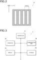
- the multi-slit 12 (G0 grating) is a diffraction grating, and as illustrated in FIG. 2 , a plurality of slits are arranged and provided at regular intervals in an x direction orthogonal to a radiation irradiation axis direction (here, the z direction).
- the multi-slit 12 is formed on a substrate having a low radiation absorption rate such as silicon and glass, with a high-radiation shielding material, that is, a material having a high radiation absorption rate such as tungsten, lead and gold.
- a resist layer is masked in a slit shape through photolithography, and UV is radiated so that a pattern of the slits is transferred to the resist layer. Slit structures having the same shape as the pattern are obtained through exposure, and a metal is embedded between the slit structures by electroforming, thereby the multi-slit 12 is formed.
- a slit period (grating period) of the multi-slit 12 is 1 to 60 ( ⁇ m).
- the slit period is set so that a distance between adjacent slits becomes one period as illustrated in FIG. 2 .
- a width of the slit (a length of each slit in a slit period direction (x direction)) is a length of 1 to 60 (%) of the slit period, and more preferably 10 to 40 (%).
- a height of the slit (a height in the z direction) is 1 to 1500 ( ⁇ m) and preferably 30 to 1000 ( ⁇ m).
- the multi-slit 12 is supported by the attachment arm 12b and attached to the base 19. Note that the multi-slit 12 (G0 grating) does not have to be provided if a focus of the X-ray tube of the radiation source 11 is small, for example, like a micro focus ray source.
- the added filter/collimator 112 limits an irradiation region of the X-ray to be radiated from the radiation source 11 and removes a low energy component that does not contribute to imaging among the X-ray radiated from the radiation source 11.
- the second cover unit 130 includes the subject stand 13, the first grating 14, the second grating 15, a movement mechanism 15a, the radiation detector 16, and the like.
- the second cover unit 130 which has an upper surface that serves as the subject stand 13, protects internal components from damage by contact of a subject H or an engineer and intrusion of dust by covering the periphery of the subject stand 13 with a cover member. Further, a temperature inside the unit is less likely to be affected by the influence of ambient air, so that it is possible to reduce fluctuation of grating positions due to thermal expansion, or the like, of the first grating 14 and the second grating 15.
- the subject stand 13 is a stand on which the subject H is to be placed. Further, the subject stand 13 is movable in a two-dimensional direction + rotation (XY axis + ⁇ axis).
- the first grating 14 (G1 grating) is a diffraction grating in which a plurality of slits are arranged and provided in the x direction orthogonal to the z direction that is the radiation irradiation axis direction in a similar manner to the multi-slit 12.
- the first grating 14 can be formed through photolithography using UV in a similar manner to the multi-slit 12, or a grating structure may be formed only with silicon by performing deep drilling processing on a silicon substrate with a fine wire using a so-called ICP method.
- a slit period of the first grating 14 is 1 to 20 ( ⁇ m).
- a width of the slit is 20 to 70 (%) of the slit period and preferably 35 to 60 (%).
- a height of the slit is 1 to 100 ( ⁇ m).
- the second grating 15 (G2 grating) is a diffraction grating in which a plurality of slits are arranged and provided in the x direction orthogonal to the z direction that is the radiation irradiation axis direction in a similar manner to the multi-slit 12.
- the second grating 15 can also be formed through photolithography.
- a slit period of the second grating 15 is 1 to 20 ( ⁇ m).
- a width of the slit is 30 to 70 (%) of the slit period and preferably 35 to 60 (%).
- a height of the slit is 1 to 100 ( ⁇ m).
- the movement mechanism 15a that moves the second grating 15 in the x direction is provided adjacent to the second grating 15. As the movement mechanism 15a, a mechanism having any configuration may be used if the mechanism can linearly move the second grating 15 in the x direction through driving by a motor, or the like.
- the radiation detector 16 in which conversion elements that generate electrical signals in accordance with radiated radiation are disposed in two dimensions, reads the electrical signals generated by the conversion elements as image signals.
- a pixel size of the radiation detector 16 is 10 to 300 ( ⁇ m) and more preferably 50 to 200 ( ⁇ m).
- the radiation detector 16 is preferably fixed at the base 19 so as to abut on the second grating 15. This is because as a distance between the second grating 15 and the radiation detector 16 becomes greater, a Moire fringe image obtained by the radiation detector 16 becomes more blurred.
- a flat panel detector can be used as the radiation detector 16. While the FPD includes an indirect conversion type in which radiation is converted into an electrical signal using a photoelectric conversion element via a scintillator, and a direct conversion type in which radiation is directly converted into an electrical signal, either may be used.
- the radiation detector 16 a radiation detector in which an intensity modulation effect of the second grating 15 is provided may be used.
- a radiation detector in which an intensity modulation effect of the second grating 15 is provided may be used.
- a slit scintillator detector obtained by drilling a groove in the scintillator to obtain a grid-like scintillator may be used as the radiation detector 16.
- the radiation detector 16 serves as both the second grating 15 and the radiation detector 16, and thus, it is not necessary to separately provide the second grating 15.
- the X-ray Talbot imaging apparatus including the slit scintillator detector is equivalent to the X-ray Talbot imaging apparatus including the second grating 15 and the radiation detector 16.
- the Talbot-Lau interferometer of the body 1 is configured so that the subject H on a lower side is irradiated with an X-ray from the radiation source 11 provided on an upper side (a case of a vertical type)
- the present invention is not limited to this, and the Talbot-Lau interferometer may be configured so that the subject H on an upper side is irradiated with an X-ray from the radiation source 11 provided on a lower side.
- the Talbot-Lau interferometer may be configured so that an X-ray is radiated in an arbitrary direction such as a horizontal direction (a case of a so-called horizontal type).
- the camera 21, which can acquire images including depth information is an RGB-D camera (red green blue-depth camera) that can obtain an RGB-D image including three-dimensional point cloud data.
- the camera 21 can acquire three-dimensional information and the RGB image (two-dimensional image).
- the camera 21 is adjusted in accordance with an absolute position of the X-ray Talbot imaging apparatus 100 (G0 grating, G1 grating, G2 grating). Specifically, coordinates of the RGB-D image captured by the camera 21 are made to match coordinates of the reconstructed image captured and generated by the radiation detector 16. For example, X-ray high-absorbent markers are disposed at five locations of four corners and the center of the imaging range on the subject stand 13, and coordinates of the captured RGB-D image are made to match coordinates of the absorption image.
- the camera 21 functions as an imager that captures an image from which relative positions (relative position information) of two or more dimensions of the subject with respect to the gratings can be acquired.
- the relative position information may be acquired by utilizing a plurality of cameras. For example, there is a case where means for acquiring a two-dimensional image of the subject H and means for acquiring a three-dimensional image are individually provided. Further, the relative position information may be acquired from movement information of a robot arm by putting the subject H into the robot arm. Further, the relative position information may be acquired with high accuracy using a 3D scanner. Still further, if the subject H is a flat plate, thickness information may be obtained by performing imaging from the side with a camera (combination of a normal camera from above and a normal camera from the side).
- the controller 5 includes a controller 51, an operator 52, a display 53, a communication unit 54 and a storage 55.
- the controller 51 includes a central processing unit (CPU), a random access memory (RAM), and the like.
- the controller 51 is connected to the respective components of the body 1 (for example, the radiation source 11, the radiation detector 16, the movement mechanism 15a and the camera 21) and controls operation of the respective components. Further, the controller 51 executes various kinds of processing including imaging processing a which will be described later in cooperation with a program stored in the storage 55.
- the controller 51 functions as a generator that generates a reconstructed image on the basis of a Moire fringe image obtained by performing imaging by irradiating the subject H disposed at a position overlapping the radiation irradiation axis direction with radiation by the radiation source 11 in cooperation with the radiation source 11, the gratings (the multi-slit 12, the first grating 14, the second grating 15), the radiation detector 16, and the like.
- the controller 51 functions as an acquirer that acquires relative position information that is relative positions in two or more dimensions of the subject H with respect to the gratings.
- the controller 51 functions as a controller that associates the reconstructed image which will be described later with the relative position information.
- the operator 52 which includes a touch panel integrally constituted with a display of the display 53 in addition to an exposure switch and keys to be used for input operation such as imaging conditions, generates an operation signal in accordance with the operation and outputs the operation signal to the controller 51.
- the display 53 displays an operation screen, an operating condition of the body 1, and the like, on the display in accordance with display control by the controller 51.
- the communication unit 54 which includes a communication interface, performs communication with external equipment on a network.
- the storage 55 which includes a non-volatile semiconductor memory, a hard disk, and the like, stores a program to be executed by the controller 51, data necessary for execution of the program, imaging history, and the like.
- the imaging history is associated with imaging conditions, subject material information/molding conditions, a parent and child relationship of the subject (a child sample which is part of a parent sample, with respect to the parent sample), environment information such as a temperature/vibration/air pressure at the time of imaging, various kinds of examination data (such as in-situ and an ash measurement result), and the like.
- the imaging history and the associated information may be recorded in an image header, and the like, and then recorded in the storage 55.
- a database (DB) may be provided separately from the controller 5, and the imaging history and the associated information may be managed in the DB.
- the X-ray that has passed forms an image at fixed intervals in the z direction.
- This image will be referred to as a self-image, and a phenomenon that the self-image is formed will be referred to as a Talbot effect.
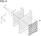
- the second grating 15 is disposed substantially parallel to the self-image at a position at which the self-image is formed, and a Moire fringe image (indicated with Mo in FIG. 4 ) can be obtained with the X-ray that has passed through the second grating 15.
- the first grating 14 forms a periodic pattern
- the second grating 15 converts the periodic pattern to a Moire fringe.
- the Moire fringe on the Moire fringe image becomes disordered from a boundary of a periphery of the subject H as illustrated in FIG. 4 .
- a subject image can be obtained by detecting the disorder of the Moire fringe by processing the Moire fringe image. This is principle of the Talbot interferometer.
- the multi-slit 12 is disposed at a position which is between the radiation source 11 and the first grating 14 and which is close to the radiation source 11, and X-ray imaging is performed using the Talbot-Lau interferometer. While it is assumed in the Talbot interferometer that the radiation source 11 is an ideal point source, in actual imaging, a focus having a focal diameter that is large to some extent is used, and thus, an effect of X-rays being radiated as if a plurality of point sources continued is provided by the multi-slit 12. This is an X-ray imaging method by the Talbot-Lau interferometer, and a Talbot effect similar to the effect of the Talbot interferometer can be obtained even in a case where a focal diameter is large to some extent.
- a Moire fringe image necessary for generating a reconstructed image of the subject H is captured using a fringe scanning method.
- Fringe scanning typically refers to performing imaging M times (imaging of M steps) (M is a positive integer, M > 2 in the absorption image, M > 3 in a differential phase image and a small-angle scattering image) by relatively moving one (in the present embodiment, the second grating 15) or two of the gratings (the multi-slit 12, the first grating 14, the second grating 15) in the slit period direction (x direction) and acquiring M Moire fringe images necessary for generating a reconstructed image.
- M Moire fringe images are acquired by repeating imaging while moving the grating in the slit period direction by d/M ( ⁇ m) each time.
- the reconstructed image to be generated on the basis of the Moire fringe image includes a small-angle scattering image, a differential phase image, and an absorption image.
- the small-angle scattering image is an image of scattering of X-rays in a fine structure and has a signal value that becomes greater as scattering of X-rays becomes larger.
- a fine structure aggregate of several micrometers to several tens of micrometers smaller than a pixel size can be grasped.
- the differential phase image is an image of refraction of the X-ray by the subject and has a signal value that becomes greater as refraction of the X-ray becomes greater. While lighter elements have lower sensitivity in the absorption image, in the differential phase image, light elements can maintain high sensitivity, so that change of a substance that is difficult to be grasped in the absorption image can be grasped.
- the absorption image is an image of absorption of the X-ray by the subject and is equivalent to a plain X-ray image in related art.
- a subject Moire fringe image (Moire fringe image including the subject).
- the reconstructed image is generated on the basis of the corrected subject Moire fringe image and a back ground (BG) Moire fringe image for_ generating the reconstructed image.
- the BG Moire fringe image is a Moire fringe image acquired by moving the second grating 15 under the same X-ray irradiation conditions (a tube voltage, an mAS value, a filter) as the conditions for the subject Moire fringe image in a state where the subject H is removed from the subject stand 13.
- the absorption image is generated by logarithmically converting a transmittance image generated by dividing an added image of M subject Moire fringe images by an added image of M BG Moire fringe images.
- the differential phase image is generated by generating a differential phase image including the subject and a differential phase image without the subject by calculating a phase of Moire fringe using principle of a fringe scanning method for each of the subject Moire fringe image and the BG Moire fringe image and subtracting the generated differential phase image without the subject from the generated differential phase image including the subject.
- FIG. 5 is a flowchart illustrating imaging processing a to be executed by cooperation of the controller 51 of the X-ray Talbot imaging apparatus 100 and the program stored in the storage 55.
- the imaging processing a is processing of generating an image of a range larger than the imaging range of one time by moving the subject H to four positions, performing imaging at imaging positions A to D and combining reconstructed images (the small-angle scattering image, the differential phase image, the absorption image) generated for each of the imaging positions A to D.
- the controller 51 acquires M BG Moire fringe images (Ref images) without the subject by moving the second grating 15 under the same X-ray irradiation conditions (a tube voltage, an mAs value, a filter) as the conditions for the subject Moire fringe image in a state where the subject H is not disposed on the subject stand 13 (step S11). Note that it is assumed in Example 1 that four images are acquired.
- the controller 51 causes the camera 21 to image the subject H to acquire an RGB-D image (step S12).
- the controller 51 acquires relative position information that is relative positions in two or more dimensions of the subject H with respect to the gratings from the RGB-D image (step S13).
- the controller 51 controls the radiation source 11, the movement mechanism 15a, the radiation detector 16, and the like, to perform imaging (referred to as Talbot imaging) for acquiring Moire fringe images (Spl images) by utilizing the above-described Talbot effect (step S14).
- M four subject Moire fringe images (Spl images) are acquired while moving the grating (in the present embodiment, the second grating 15) in the slit period direction by the fringe scanning method.
- step S15 the controller 51 determines whether or not the position of the subject H is changed.
- imaging is performed at four locations of the imaging positions A to D illustrated in FIG. 6 , and thus, four loops of the processing from step S 11 to step S 14 are performed.
- the controller 51 repeats change of the imaging position four times and then determines that the position of the subject H is not changed (step S15: No), and the processing proceeds to step S16.
- step S15: Yes the user moves the subject H from the subject stand 13, and the processing proceeds to step S11.
- step S15 the processing may proceed to step S12 without acquiring the BG Moire fringe images again.
- the subject H may be manually moved from the subject stand 13, a motorized stage is preferably utilized in terms of movement accuracy.
- the reconstructed images (the small-angle scattering image, the differential phase image, the absorption image) are generated on the basis of the BG fringe Moire images and the subject Moire fringe images at the respective imaging positions (step S16).
- the reconstructed images are stored in the storage 55 in association with the relative position information at the respective imaging positions, image numbers for identifying the images, test conditions, imaging conditions in Talbot imaging, imaging date and time, and the like.
- the controller 51 derives a position correction amount on the basis of the relative position information at the respective imaging positions (step S17). Derivation of the position correction amount will be described later. For example, a gradient descent method can be used. Note that in a case where the subject is thick, influence of oblique incidence of the X-ray cannot be ignored, and thus, this influence is taken into account.
- the controller 51 corrects displacement of the reconstructed images at the respective positions on the basis of the position correction amount derived in step S17 and combines the reconstructed images at the respective positions (step S18). Note that in a case where the position of the subject H is never moved, the processing may be finished without executing step S17 and step S18. Further, the displacement may be corrected for the subject Moire fringe image before the reconstructed image is created. This method has higher accuracy.
- the positions can be aligned with high accuracy, and an image of a range larger than the imaging range of one time can be generated. Further, the positions can be aligned without using the marker, and thus, a defect portion does not occur.
- Example 2 is processing of generating a small-angle scattering image by performing imaging while moving the subject H to three imaging positions (having relative angles of 0°, 60°, 120° with respect to the grating) as illustrated in FIG. 7 and combining the reconstructed images (the small-angle scattering images) generated for each imaging position. Note that flow of the processing is the same as the flow in Example 1, and the controller 51 generates a small-angle scattering oriented image in step S18.
- the small-angle scattering oriented image is an image representing orientation of a substance such as a fiber inside the subject H obtained by analyzing a plurality of small-angle scattering images generated on the basis of the Moire fringe images captured while setting three or more relative angles between the subject H and the grating around the radiation irradiation axis.
- Example 3 is processing of generating the reconstructed images (the small-angle scattering image, the differential phase image, the absorption image) by performing imaging while moving the subject H to two imaging positions (having relative angles of 0° and 90° with respect to the grating) as illustrated in FIG. 8 and combining the reconstructed images (the small-angle scattering image, the differential phase image, the absorption image) generated for each imaging position.
- flow of the processing is the same as the flow in Example 1, and the controller 51 generates the combined reconstructed image (the small-angle scattering image, the differential phase image, the absorption image) in step S18.
- a value of each pixel is obtained by using an average value of each pixel and a square-root of sum of squares of each pixel for each pixel as in the following expression.
- influence by orientation of the subject H with respect to the grating can be reduced.
- Example 4 is processing of generating reconstructed images (the small-angle scattering image, the differential phase image, the absorption image) of a parent sample by combining the reconstructed images (the small-angle scattering image, the differential phase image, the absorption image) obtained by imaging the subject H (parent sample) for each of six child samples as illustrated in FIG. 9 on the basis of position information (relative positions in two or more dimensions of the subject H with respect to the gratings) of the child samples with respect to the parent sample.
- flow of the processing is the same as the flow in Example 1, and the controller 51 generates the reconstructed images (the small-angle scattering image, the differential phase image, the absorption image) of the parent sample in step S18. Further, it is necessary to cut out the child samples from the parent sample and manage a parent and child relationship of the samples and cut-out positions in the DB.
- a state of the parent sample can be restored with high accuracy from images of a plurality of child samples.
- FIG. 10 is a flowchart illustrating imaging possible/impossible determination processing b to be executed by cooperation of the controller 51 of the X-ray Talbot imaging apparatus 100 and the program stored in the storage 55.
- the imaging possible/impossible determination processing b is processing of determining whether or not imaging is possible from material and composition information input using the operator 52, thickness information of the subject H obtained from the RGB-D image, past imaging information, and current imaging conditions.
- the controller 51 obtains material and composition information of the subject H via the operator 52 (step S21).
- the controller 51 causes the camera 21 to image the subject H to acquire the RGB-D image (step S22).
- the controller 51 acquires relative position information (particularly, thickness information) that is relative positions in two or more dimensions of the subject H with respect to the gratings from the RGB-D image (step S23).
- the controller 51 determines whether or not imaging is possible by matching the current imaging conditions with reference to imaging conditions, and the like, of a similar subject imaged in the past stored in the storage 55 from the material and composition information and the thickness information (step S24). Note that imaging possible conditions may be derived.
- the controller 51 determines that imaging is impossible. Further, the controller 51 derives setting (mAs value) of the radiation source 11 in accordance with the thickness.
- whether or not imaging is possible is determined by referring to the past imaging information
- the present invention is not limited to this.
- whether or not imaging is possible may be determined by calculating a transmission amount of the X-ray on the basis of physical information of the subject H.
- the controller 51 makes an imaging possible/impossible notification via the display 53 (step S25). Finally, the controller 51 makes a notification of imaging possible conditions via the display 53 (step S26).
- a notification method is not limited to screen display and may be sound, speech or LED display. It is also possible to employ a configuration where imaging is not started in a case where it is determined that imaging is impossible. Further, it is also possible to employ a configuration where, when an instruction to start imaging is issued, in a case where a favorable image cannot be obtained even if imaging is performed, imaging is allowed after a notification indicating that a favorable image cannot be obtained is made. Further, in a case where imaging is possible, the processing may be finished without making an imaging possible/impossible notification (step S25) and making a notification of imaging possible conditions (step S26).
- the user can therefore grasp conditions for being able to capture an image having necessary drawing performance (such as contrast) with high accuracy. Further, it is possible to reduce work for determining whether or not imaging is possible.
- the second part from the top in FIG. 11 indicates relative position information of the subject H in a case where the subject is considered in three dimensions at the two imaging positions.
- a circle on the subject H is a marker. It can be known from the right and left figures that the subject H is rotated by 90° around the radiation irradiation axis. Note that the marker is provided for facilitating understanding of description and the drawings, and this marker is not necessary in the present invention.
- the third part from the top in FIG. 11 is relative position information of the reconstructed images (a reconstructed image A0, a reconstructed image B0) and the subject H at the two imaging positions.
- the reconstructed images have two dimensions, and thus, are compressed in the z direction to convert the three-dimensional relative position information into two-dimensional relative position information.
- the fourth part from the top in FIG. 11 is relative position information of a reconstructed image B1 and the subject H obtained by rotating by -90° the reconstructed image of the subject H at the imaging position rotated around the radiation irradiation axis by 90°.
- the position correction amount is derived by comparing the relative position information at the same location of the subject H in the reconstructed image A0 and the reconstructed image B1.
- the position correction amount is derived in a parallel direction (Xcor, Ycor) and in a rotation direction ( ⁇ Cor).
- Xcor, Ycor and ⁇ Cor such that diff becomes a minimum are derived using the gradient descent method, and displacement correction (parallel movement and rotational movement) is applied to the reconstructed image A0 or the reconstructed image B1.
- diff x 3 ⁇ X 1 + x 4 ⁇ X 2 + y 3 ⁇ Y 1 + y 4 ⁇ Y 2
- imaging is performed using an RGB-D camera also in imaging using other modality in a similar manner in addition to the first embodiment.
- the controller 51 acquires a captured image and relative position information (acquired from the RGB-D image in other modality) from the other modality and causes a subject image of the other modality to match a subject image of the X-ray Talbot imaging apparatus 100 on the basis of the relative position information.
- the other modality only requires to be modality that outputs image data from which an imaging range and a subject can be grasped in the same coordinate system and can include, for example, SEM, ⁇ CT and a high-resolution Talbot.
- the controller 51 functions as an acquirer that acquires relative position information (relative position information acquired in the other modality, and relative position information in imaging using the X-ray Talbot imaging apparatus 100) that is relative positions in two or more dimensions of the subject with respect to the gratings.
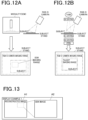
- FIG. 13 is an example in which the reconstructed image A1 obtained by the X-ray Talbot imaging apparatus 100 and an image A2 obtained by other modality (SEM) are displayed side by side on the display 53.
- a position coordinate of the reconstructed image A1 corresponds to a position coordinate of the image A2, and thus, the image A2 corresponding to part of the reconstructed image A1 can be displayed.
- FIG. 14 is an example in which a reconstructed image A3 obtained by the X-ray Talbot imaging apparatus 100 and an image A4 and an image A5 obtained by other modality (SEM) are displayed side by side on the display 53.
- a position coordinate of the reconstructed image A3 corresponds to position coordinates of the image A4 and the image A5, and thus, the image A4 and the image A5 corresponding to part of the reconstructed image A3 can be displayed.
- the positions in two or more dimensions of the subject H with respect to the gratings it is possible to align the positions with high accuracy and make positions match among images of two or more different kinds of modality. Further, the positions can be aligned without using a marker, so that a defect portion does not occur.
- data in a format that can be fed back to computer-aided engineering (CAE) is generated by the controller 51 making coordinates of the reconstructed images (the small-angle scattering image, the differential phase image, the absorption image) obtained by the X-ray Talbot imaging apparatus 100 match coordinates of an image created by a CAD on the basis of the relative positions in two or more dimensions of the subject H with respect to the gratings obtained from the RGB-D image by using the CAD in addition to the first embodiment.
- CAE computer-aided engineering
- the controller 51 functions as an acquirer that acquires relative position information (coordinate information of the image created by the CAD and relative position information obtained from the RGB-D image) that is relative positions in two or more dimensions of the subject with respect to the gratings.
- a fluid analysis result A6 of a two-dimensional image can be obtained.
- a position of the fluid analysis result A6 of the two-dimensional image is made to match a position of the reconstructed image A7 obtained by the X-ray Talbot imaging apparatus 100.
- the positions in two or more dimensions of the subject H with respect to the grating it is possible to align the positions with high accuracy and make positions match the positions in the image obtained from the CAD. Further, the positions can be aligned without using a marker, so that a defect portion does not occur.
- the third embodiment is useful because the fluid analysis result and an oriented image can be accurately compared.
- the reconstructed image and the RGB-D image can be displayed in an overlay manner. This can allow confirmation while comparing the images.
- the positions can be aligned with higher accuracy by grasping a state of the subject H from a relationship between environment information such as a temperature/vibration/air pressure at the time of imaging and various kinds of examination data (such as in-situ and an ash measurement result).
- the radiographic imaging apparatus in which a radiation source, a plurality of gratings and a radiation detector are provided side by side in a radiation irradiation axis direction, including a generator (controller 51) that generates a reconstructed image on the basis of a Moire fringe image obtained by performing imaging by irradiating a subject disposed at a position overlapping the radiation irradiation axis direction with radiation by the radiation source, an acquirer (controller 51) that acquires relative position information that is relative positions in two or more dimensions of the subject with respect to the gratings, a controller (controller 51) that associates the reconstructed image with the relative position information, it is possible to align positions of images obtained by imaging a plurality of times, the subject that has no significant characteristics on the images and has a size exceeding the imaging range of one time, with high accuracy without displacement.
- a generator that generates a reconstructed image on the basis of a Moire fringe image obtained by performing imaging by irradiating a subject
- the acquirer may acquire a captured image and relative position information acquired by modality different from the radiographic imaging apparatus.
- the acquirer may acquire relative position information from an image captured with an imager that captures an image from which the relative position information can be acquired.
- the generator generates a plurality of reconstructed images and generates a combined image by correcting positions of the plurality of reconstructed images using the relative position information, so that it is possible to align positions of images obtained by imaging a plurality of times, a subject that has no significant characteristics on the images and has a size exceeding an imaging range of one time, with high accuracy without displacement and combine the images with high accuracy.
- the generator generates a reconstructed image of the parent sample by combining reconstructed images of the subject cut out from the same parent sample using the relative position information of the subject cut out from the parent sample, so that it is possible to align positions of images obtained by imaging a plurality of times, a subject that has no significant characteristics on the images and has a size exceeding an imaging range of one time, with high accuracy without displacement and combine the images with high accuracy.
- the generator generates a plurality of reconstructed images, which are small-angle scattering images, and generates an oriented image using the small-angle scattering images at three or more angles rotated around the radiation irradiation axis, for which positions are corrected using the relative position information, so that it is possible to align positions of images obtained by imaging a plurality of times, a subject that has no significant characteristics on the images and has a size exceeding an imaging range of one time, with high accuracy without displacement and obtain an oriented image with high accuracy.
- the generator generates a plurality of reconstructed images, which are small-angle scattering images or differential phase images, and generates an image by synthesizing the small-angle scattering images or the differential phase images at two or more angles rotated around the radiation irradiation axis, for which positions are corrected using the relative position information, so that it is possible to align positions of images obtained by imaging a plurality of times, a subject that has no significant characteristics on the images and has a size exceeding an imaging range of one time, with high accuracy without displacement and combine the images with high accuracy.
- the generator associates the relative position information with coordinate information of a computer-aided design (CAD) model and generates data in a format that can be fed back to computer-aided engineering (CAE), so that it is possible to align positions of a CAD image and the reconstructed image with high accuracy without displacement.
- CAD computer-aided design
- CAE computer-aided engineering
- the controller determines whether or not imaging is possible from the material and/or composition information of the subject and the thickness information of the subject obtained from the relative position information, so that the user can reduce work for determining whether or not imaging is possible.
- the controller derives imaging possible conditions from the material and/or composition information of the subject and the thickness information of the subject obtained from the relative position information, so that the user can set appropriate imaging possible conditions by the imaging possible conditions being derived.
- an image generation method is a method to be performed by a radiographic imaging apparatus in which a radiation source, a plurality of gratings and a radiation detector are provided side by side in a radiation irradiation axis direction, the method including generating by a generator, a reconstructed image on the basis of a Moire fringe image obtained by performing imaging by irradiating a subject disposed at a position overlapping the radiation irradiation axis direction with radiation by the radiation source, acquiring by an acquirer, relative position information that is relative positions in two or more dimensions of the subject with respect to the gratings, and associating by a controller, the reconstructed image with the relative position information, so that it is possible to align positions and combine images obtained by imaging a plurality of times, a subject that has no significant characteristics on the images and has a size exceeding an imaging range of one time, with high accuracy without displacement to generate the reconstructed image.
- a radiographic imaging system is a radiographic imaging system including the above-described radiographic imaging apparatus, and at least one apparatus of ⁇ CT, SEM or high-resolution Talbot and matches positions of an analysis result of the apparatus and the reconstructed image using the relative position information, so that it is possible to align positions of the analysis result of the other apparatus and the reconstructed image obtained from the radiographic imaging apparatus with high accuracy without displacement.
- the radiographic imaging system includes the above-described radiographic imaging apparatus and displays the reconstructed image and an optical image obtained by an imager in a superimposed manner using the relative position information, so that it is possible to superimpose the images without displacement.
- a program causes a computer of a radiographic imaging apparatus in which a radiation source, a plurality of gratings and a radiation detector are provided side by side in a radiation irradiation axis direction to function as a generator that generates a reconstructed image on the basis of a Moire fringe image obtained by performing imaging by irradiating a subject disposed at a position overlapping the radiation irradiation axis direction with radiation by the radiation source, an acquirer that acquires relative position information that is relative positions in two or more dimensions of the subject with respect to the gratings, and a controller that associates the reconstructed image with the relative position information, so that it is possible to align positions of images obtained by imaging a plurality of times, a subject that has no significant characteristics on the images and that has a size exceeding an imaging range of one time, with high accuracy without displacement.
- the present invention may be applied to a test apparatus using a Talbot-Lau interferometer of a scheme in which one or two grating of the multi-slit 12, the first grating 14 or the second grating 15 is moved at the time of imaging using the fringe scanning method.
- the present invention may be applied to a test apparatus using a Talbot interferometer of a scheme in which one of the first grating 14 or the second grating 15 is moved with respect to the other grating. Further, the present invention may be applied to a test apparatus using a Talbot-Lau interferometer of a scheme in which one of the multi-slit 12 or the first grating 14 is moved with respect to the other grating. Further, the present invention may be applied to a Talbot-Lau interferometer, a Talbot interferometer, or a Talbot-Lau interferometer using a Fourier transform method that does not require fringe scanning.
- the present invention can be implemented if the small-angle scattering image and/or the differential phase image can be generated.
- a hard disk, a non-volatile memory of a semiconductor, or the like is used as a computer-readable medium for the program according to the present invention
- the present invention is not limited to this example.
- a portable recording medium such as a CD-ROM can be applied.
- a carrier wave can be applied as a medium that provides data of the program according to the present invention via a communication line.
Landscapes
- Health & Medical Sciences (AREA)
- Life Sciences & Earth Sciences (AREA)
- Engineering & Computer Science (AREA)
- Medical Informatics (AREA)
- Radiology & Medical Imaging (AREA)
- Molecular Biology (AREA)
- Biophysics (AREA)
- Nuclear Medicine, Radiotherapy & Molecular Imaging (AREA)
- Optics & Photonics (AREA)
- Pathology (AREA)
- Physics & Mathematics (AREA)
- Biomedical Technology (AREA)
- Heart & Thoracic Surgery (AREA)
- High Energy & Nuclear Physics (AREA)
- Surgery (AREA)
- Animal Behavior & Ethology (AREA)
- General Health & Medical Sciences (AREA)
- Public Health (AREA)
- Veterinary Medicine (AREA)
- Toxicology (AREA)
- Computer Vision & Pattern Recognition (AREA)
- Analysing Materials By The Use Of Radiation (AREA)
- Apparatus For Radiation Diagnosis (AREA)
Applications Claiming Priority (1)
| Application Number | Priority Date | Filing Date | Title |
|---|---|---|---|
| JP2021203609A JP7750078B2 (ja) | 2021-12-15 | 2021-12-15 | 放射線撮影装置、画像生成方法、放射線撮影システム、及びプログラム |
Publications (2)
| Publication Number | Publication Date |
|---|---|
| EP4197445A1 true EP4197445A1 (fr) | 2023-06-21 |
| EP4197445B1 EP4197445B1 (fr) | 2024-04-03 |
Family
ID=84358046
Family Applications (1)
| Application Number | Title | Priority Date | Filing Date |
|---|---|---|---|
| EP22207427.0A Active EP4197445B1 (fr) | 2021-12-15 | 2022-11-15 | Appareil d'imagerie radiographique, procédé de génération d'image, système d'imagerie radiographique et programme |
Country Status (3)
| Country | Link |
|---|---|
| US (1) | US20230181136A1 (fr) |
| EP (1) | EP4197445B1 (fr) |
| JP (1) | JP7750078B2 (fr) |
Families Citing this family (4)
| Publication number | Priority date | Publication date | Assignee | Title |
|---|---|---|---|---|
| US12072302B2 (en) * | 2021-12-20 | 2024-08-27 | Shimadzu Corporation | X-ray phase imaging system |
| JPWO2024024796A1 (fr) * | 2022-07-29 | 2024-02-01 | ||
| WO2024024797A1 (fr) * | 2022-07-29 | 2024-02-01 | コニカミノルタ株式会社 | Système de gestion d'image, dispositif de gestion d'image, procédé de gestion d'image et programme de gestion d'image |
| KR102768747B1 (ko) * | 2024-04-22 | 2025-02-18 | 테크밸리 주식회사 | 피검사물 적응형 ct 장치 |
Citations (4)
| Publication number | Priority date | Publication date | Assignee | Title |
|---|---|---|---|---|
| JPH0480591B2 (fr) | 1983-10-21 | 1992-12-18 | Sony Corp | |
| US20160042533A1 (en) * | 2014-08-06 | 2016-02-11 | Konica Minolta, Inc. | X-ray imaging system and image processing device |
| US20200333265A1 (en) * | 2019-04-22 | 2020-10-22 | Shimadzu Corporation | X-ray phase imaging apparatus and x-ray phase contrast image generation method |
| US20210015437A1 (en) * | 2017-12-26 | 2021-01-21 | Shimadzu Corporation | X-ray imaging apparatus |
Family Cites Families (2)
| Publication number | Priority date | Publication date | Assignee | Title |
|---|---|---|---|---|
| JP2887517B2 (ja) * | 1990-10-09 | 1999-04-26 | 徹 吉澤 | 実体格子型のモアレトポグラフィーによる高感度三次元測定法 |
| JP7234795B2 (ja) * | 2019-05-17 | 2023-03-08 | コニカミノルタ株式会社 | 検査装置及び画像生成方法 |
-
2021
- 2021-12-15 JP JP2021203609A patent/JP7750078B2/ja active Active
-
2022
- 2022-11-15 EP EP22207427.0A patent/EP4197445B1/fr active Active
- 2022-11-30 US US18/060,255 patent/US20230181136A1/en not_active Abandoned
Patent Citations (4)
| Publication number | Priority date | Publication date | Assignee | Title |
|---|---|---|---|---|
| JPH0480591B2 (fr) | 1983-10-21 | 1992-12-18 | Sony Corp | |
| US20160042533A1 (en) * | 2014-08-06 | 2016-02-11 | Konica Minolta, Inc. | X-ray imaging system and image processing device |
| US20210015437A1 (en) * | 2017-12-26 | 2021-01-21 | Shimadzu Corporation | X-ray imaging apparatus |
| US20200333265A1 (en) * | 2019-04-22 | 2020-10-22 | Shimadzu Corporation | X-ray phase imaging apparatus and x-ray phase contrast image generation method |
Also Published As
| Publication number | Publication date |
|---|---|
| JP7750078B2 (ja) | 2025-10-07 |
| US20230181136A1 (en) | 2023-06-15 |
| JP2023088704A (ja) | 2023-06-27 |
| EP4197445B1 (fr) | 2024-04-03 |
Similar Documents
| Publication | Publication Date | Title |
|---|---|---|
| EP4197445B1 (fr) | Appareil d'imagerie radiographique, procédé de génération d'image, système d'imagerie radiographique et programme | |
| US7186023B2 (en) | Slice image and/or dimensional image creating method | |
| US6960020B2 (en) | Image positioning method and system for tomosynthesis in a digital X-ray radiography system | |
| JP4551919B2 (ja) | 断層撮影の検査システムおよびその方法 | |
| US7400704B1 (en) | High resolution direct-projection type x-ray microtomography system using synchrotron or laboratory-based x-ray source | |
| JP4415762B2 (ja) | 断層撮影装置 | |
| JP7198457B2 (ja) | インテリアct位相イメージングx線顕微鏡装置 | |
| JP5783987B2 (ja) | 放射線撮影装置 | |
| JPWO2019008620A1 (ja) | X線ct装置 | |
| JP4537090B2 (ja) | トモシンセシス装置 | |
| CN112189134B (zh) | X射线成像装置 | |
| JP2008200361A (ja) | X線撮影システム | |
| JP2007309687A (ja) | 断層撮影装置 | |
| CN109106387B (zh) | X射线相位差成像装置 | |
| US12467883B2 (en) | X-ray phase imaging apparatus and display method of preview image in X-ray phase imaging apparatus | |
| JP4129572B2 (ja) | 傾斜三次元x線ct画像の再構成方法 | |
| JP6789591B2 (ja) | 放射線位相撮像装置 | |
| JP2014155509A (ja) | 放射線撮影システム | |
| KR102426991B1 (ko) | 방사선 화상 생성 장치 | |
| TW200302919A (en) | X-ray inspection apparatus, and the control method and adjust method of the same | |
| JP2024158874A (ja) | X線タルボ撮影装置及びx線タルボ撮影方法 | |
| JP4788272B2 (ja) | X線断層撮像装置及びx線断層撮像方法 | |
| JP2007322384A (ja) | X線断層撮像装置及びx線断層撮像方法 | |
| JP2022010384A (ja) | X線ct装置 | |
| WO2023171726A1 (fr) | Procédé d'évaluation, dispositif d'évaluation et programme |
Legal Events
| Date | Code | Title | Description |
|---|---|---|---|
| PUAI | Public reference made under article 153(3) epc to a published international application that has entered the european phase |
Free format text: ORIGINAL CODE: 0009012 |
|
| STAA | Information on the status of an ep patent application or granted ep patent |
Free format text: STATUS: THE APPLICATION HAS BEEN PUBLISHED |
|
| AK | Designated contracting states |
Kind code of ref document: A1 Designated state(s): AL AT BE BG CH CY CZ DE DK EE ES FI FR GB GR HR HU IE IS IT LI LT LU LV MC ME MK MT NL NO PL PT RO RS SE SI SK SM TR |
|
| STAA | Information on the status of an ep patent application or granted ep patent |
Free format text: STATUS: REQUEST FOR EXAMINATION WAS MADE |
|
| 17P | Request for examination filed |
Effective date: 20230623 |
|
| RBV | Designated contracting states (corrected) |
Designated state(s): AL AT BE BG CH CY CZ DE DK EE ES FI FR GB GR HR HU IE IS IT LI LT LU LV MC ME MK MT NL NO PL PT RO RS SE SI SK SM TR |
|
| GRAJ | Information related to disapproval of communication of intention to grant by the applicant or resumption of examination proceedings by the epo deleted |
Free format text: ORIGINAL CODE: EPIDOSDIGR1 |
|
| STAA | Information on the status of an ep patent application or granted ep patent |
Free format text: STATUS: GRANT OF PATENT IS INTENDED |
|
| GRAP | Despatch of communication of intention to grant a patent |
Free format text: ORIGINAL CODE: EPIDOSNIGR1 |
|
| RIC1 | Information provided on ipc code assigned before grant |
Ipc: A61B 6/00 20060101AFI20231026BHEP |
|
| INTG | Intention to grant announced |
Effective date: 20231110 |
|
| GRAS | Grant fee paid |
Free format text: ORIGINAL CODE: EPIDOSNIGR3 |
|
| GRAA | (expected) grant |
Free format text: ORIGINAL CODE: 0009210 |
|
| STAA | Information on the status of an ep patent application or granted ep patent |
Free format text: STATUS: THE PATENT HAS BEEN GRANTED |
|
| AK | Designated contracting states |
Kind code of ref document: B1 Designated state(s): AL AT BE BG CH CY CZ DE DK EE ES FI FR GB GR HR HU IE IS IT LI LT LU LV MC ME MK MT NL NO PL PT RO RS SE SI SK SM TR |
|
| REG | Reference to a national code |
Ref country code: CH Ref legal event code: EP |
|
| REG | Reference to a national code |
Ref country code: DE Ref legal event code: R096 Ref document number: 602022002703 Country of ref document: DE |
|
| REG | Reference to a national code |
Ref country code: IE Ref legal event code: FG4D |
|
| REG | Reference to a national code |
Ref country code: LT Ref legal event code: MG9D |
|
| REG | Reference to a national code |
Ref country code: NL Ref legal event code: MP Effective date: 20240403 |
|
| REG | Reference to a national code |
Ref country code: AT Ref legal event code: MK05 Ref document number: 1671347 Country of ref document: AT Kind code of ref document: T Effective date: 20240403 |
|
| PG25 | Lapsed in a contracting state [announced via postgrant information from national office to epo] |
Ref country code: NL Free format text: LAPSE BECAUSE OF FAILURE TO SUBMIT A TRANSLATION OF THE DESCRIPTION OR TO PAY THE FEE WITHIN THE PRESCRIBED TIME-LIMIT Effective date: 20240403 |
|
| PG25 | Lapsed in a contracting state [announced via postgrant information from national office to epo] |
Ref country code: NL Free format text: LAPSE BECAUSE OF FAILURE TO SUBMIT A TRANSLATION OF THE DESCRIPTION OR TO PAY THE FEE WITHIN THE PRESCRIBED TIME-LIMIT Effective date: 20240403 |
|
| PG25 | Lapsed in a contracting state [announced via postgrant information from national office to epo] |
Ref country code: IS Free format text: LAPSE BECAUSE OF FAILURE TO SUBMIT A TRANSLATION OF THE DESCRIPTION OR TO PAY THE FEE WITHIN THE PRESCRIBED TIME-LIMIT Effective date: 20240803 |
|
| PG25 | Lapsed in a contracting state [announced via postgrant information from national office to epo] |
Ref country code: BG Free format text: LAPSE BECAUSE OF FAILURE TO SUBMIT A TRANSLATION OF THE DESCRIPTION OR TO PAY THE FEE WITHIN THE PRESCRIBED TIME-LIMIT Effective date: 20240403 |
|
| PG25 | Lapsed in a contracting state [announced via postgrant information from national office to epo] |
Ref country code: HR Free format text: LAPSE BECAUSE OF FAILURE TO SUBMIT A TRANSLATION OF THE DESCRIPTION OR TO PAY THE FEE WITHIN THE PRESCRIBED TIME-LIMIT Effective date: 20240403 Ref country code: FI Free format text: LAPSE BECAUSE OF FAILURE TO SUBMIT A TRANSLATION OF THE DESCRIPTION OR TO PAY THE FEE WITHIN THE PRESCRIBED TIME-LIMIT Effective date: 20240403 |
|
| PG25 | Lapsed in a contracting state [announced via postgrant information from national office to epo] |
Ref country code: GR Free format text: LAPSE BECAUSE OF FAILURE TO SUBMIT A TRANSLATION OF THE DESCRIPTION OR TO PAY THE FEE WITHIN THE PRESCRIBED TIME-LIMIT Effective date: 20240704 |
|
| PG25 | Lapsed in a contracting state [announced via postgrant information from national office to epo] |
Ref country code: PT Free format text: LAPSE BECAUSE OF FAILURE TO SUBMIT A TRANSLATION OF THE DESCRIPTION OR TO PAY THE FEE WITHIN THE PRESCRIBED TIME-LIMIT Effective date: 20240805 |
|
| PG25 | Lapsed in a contracting state [announced via postgrant information from national office to epo] |
Ref country code: ES Free format text: LAPSE BECAUSE OF FAILURE TO SUBMIT A TRANSLATION OF THE DESCRIPTION OR TO PAY THE FEE WITHIN THE PRESCRIBED TIME-LIMIT Effective date: 20240403 |
|
| PG25 | Lapsed in a contracting state [announced via postgrant information from national office to epo] |
Ref country code: CZ Free format text: LAPSE BECAUSE OF FAILURE TO SUBMIT A TRANSLATION OF THE DESCRIPTION OR TO PAY THE FEE WITHIN THE PRESCRIBED TIME-LIMIT Effective date: 20240403 |
|
| PG25 | Lapsed in a contracting state [announced via postgrant information from national office to epo] |
Ref country code: AT Free format text: LAPSE BECAUSE OF FAILURE TO SUBMIT A TRANSLATION OF THE DESCRIPTION OR TO PAY THE FEE WITHIN THE PRESCRIBED TIME-LIMIT Effective date: 20240403 |
|
| PG25 | Lapsed in a contracting state [announced via postgrant information from national office to epo] |
Ref country code: PL Free format text: LAPSE BECAUSE OF FAILURE TO SUBMIT A TRANSLATION OF THE DESCRIPTION OR TO PAY THE FEE WITHIN THE PRESCRIBED TIME-LIMIT Effective date: 20240403 |
|
| PG25 | Lapsed in a contracting state [announced via postgrant information from national office to epo] |
Ref country code: LV Free format text: LAPSE BECAUSE OF FAILURE TO SUBMIT A TRANSLATION OF THE DESCRIPTION OR TO PAY THE FEE WITHIN THE PRESCRIBED TIME-LIMIT Effective date: 20240403 |
|
| PG25 | Lapsed in a contracting state [announced via postgrant information from national office to epo] |
Ref country code: PT Free format text: LAPSE BECAUSE OF FAILURE TO SUBMIT A TRANSLATION OF THE DESCRIPTION OR TO PAY THE FEE WITHIN THE PRESCRIBED TIME-LIMIT Effective date: 20240805 Ref country code: PL Free format text: LAPSE BECAUSE OF FAILURE TO SUBMIT A TRANSLATION OF THE DESCRIPTION OR TO PAY THE FEE WITHIN THE PRESCRIBED TIME-LIMIT Effective date: 20240403 Ref country code: NO Free format text: LAPSE BECAUSE OF FAILURE TO SUBMIT A TRANSLATION OF THE DESCRIPTION OR TO PAY THE FEE WITHIN THE PRESCRIBED TIME-LIMIT Effective date: 20240703 Ref country code: LV Free format text: LAPSE BECAUSE OF FAILURE TO SUBMIT A TRANSLATION OF THE DESCRIPTION OR TO PAY THE FEE WITHIN THE PRESCRIBED TIME-LIMIT Effective date: 20240403 Ref country code: IS Free format text: LAPSE BECAUSE OF FAILURE TO SUBMIT A TRANSLATION OF THE DESCRIPTION OR TO PAY THE FEE WITHIN THE PRESCRIBED TIME-LIMIT Effective date: 20240803 Ref country code: HR Free format text: LAPSE BECAUSE OF FAILURE TO SUBMIT A TRANSLATION OF THE DESCRIPTION OR TO PAY THE FEE WITHIN THE PRESCRIBED TIME-LIMIT Effective date: 20240403 Ref country code: GR Free format text: LAPSE BECAUSE OF FAILURE TO SUBMIT A TRANSLATION OF THE DESCRIPTION OR TO PAY THE FEE WITHIN THE PRESCRIBED TIME-LIMIT Effective date: 20240704 Ref country code: FI Free format text: LAPSE BECAUSE OF FAILURE TO SUBMIT A TRANSLATION OF THE DESCRIPTION OR TO PAY THE FEE WITHIN THE PRESCRIBED TIME-LIMIT Effective date: 20240403 Ref country code: ES Free format text: LAPSE BECAUSE OF FAILURE TO SUBMIT A TRANSLATION OF THE DESCRIPTION OR TO PAY THE FEE WITHIN THE PRESCRIBED TIME-LIMIT Effective date: 20240403 Ref country code: CZ Free format text: LAPSE BECAUSE OF FAILURE TO SUBMIT A TRANSLATION OF THE DESCRIPTION OR TO PAY THE FEE WITHIN THE PRESCRIBED TIME-LIMIT Effective date: 20240403 Ref country code: BG Free format text: LAPSE BECAUSE OF FAILURE TO SUBMIT A TRANSLATION OF THE DESCRIPTION OR TO PAY THE FEE WITHIN THE PRESCRIBED TIME-LIMIT Effective date: 20240403 Ref country code: AT Free format text: LAPSE BECAUSE OF FAILURE TO SUBMIT A TRANSLATION OF THE DESCRIPTION OR TO PAY THE FEE WITHIN THE PRESCRIBED TIME-LIMIT Effective date: 20240403 Ref country code: RS Free format text: LAPSE BECAUSE OF FAILURE TO SUBMIT A TRANSLATION OF THE DESCRIPTION OR TO PAY THE FEE WITHIN THE PRESCRIBED TIME-LIMIT Effective date: 20240703 |
|
| REG | Reference to a national code |
Ref country code: DE Ref legal event code: R097 Ref document number: 602022002703 Country of ref document: DE |
|
| PG25 | Lapsed in a contracting state [announced via postgrant information from national office to epo] |
Ref country code: DK Free format text: LAPSE BECAUSE OF FAILURE TO SUBMIT A TRANSLATION OF THE DESCRIPTION OR TO PAY THE FEE WITHIN THE PRESCRIBED TIME-LIMIT Effective date: 20240403 |
|
| PG25 | Lapsed in a contracting state [announced via postgrant information from national office to epo] |
Ref country code: EE Free format text: LAPSE BECAUSE OF FAILURE TO SUBMIT A TRANSLATION OF THE DESCRIPTION OR TO PAY THE FEE WITHIN THE PRESCRIBED TIME-LIMIT Effective date: 20240403 |
|
| PG25 | Lapsed in a contracting state [announced via postgrant information from national office to epo] |
Ref country code: RO Free format text: LAPSE BECAUSE OF FAILURE TO SUBMIT A TRANSLATION OF THE DESCRIPTION OR TO PAY THE FEE WITHIN THE PRESCRIBED TIME-LIMIT Effective date: 20240403 Ref country code: SK Free format text: LAPSE BECAUSE OF FAILURE TO SUBMIT A TRANSLATION OF THE DESCRIPTION OR TO PAY THE FEE WITHIN THE PRESCRIBED TIME-LIMIT Effective date: 20240403 |
|
| PG25 | Lapsed in a contracting state [announced via postgrant information from national office to epo] |
Ref country code: SM Free format text: LAPSE BECAUSE OF FAILURE TO SUBMIT A TRANSLATION OF THE DESCRIPTION OR TO PAY THE FEE WITHIN THE PRESCRIBED TIME-LIMIT Effective date: 20240403 |
|
| PG25 | Lapsed in a contracting state [announced via postgrant information from national office to epo] |
Ref country code: SM Free format text: LAPSE BECAUSE OF FAILURE TO SUBMIT A TRANSLATION OF THE DESCRIPTION OR TO PAY THE FEE WITHIN THE PRESCRIBED TIME-LIMIT Effective date: 20240403 Ref country code: SK Free format text: LAPSE BECAUSE OF FAILURE TO SUBMIT A TRANSLATION OF THE DESCRIPTION OR TO PAY THE FEE WITHIN THE PRESCRIBED TIME-LIMIT Effective date: 20240403 Ref country code: RO Free format text: LAPSE BECAUSE OF FAILURE TO SUBMIT A TRANSLATION OF THE DESCRIPTION OR TO PAY THE FEE WITHIN THE PRESCRIBED TIME-LIMIT Effective date: 20240403 Ref country code: EE Free format text: LAPSE BECAUSE OF FAILURE TO SUBMIT A TRANSLATION OF THE DESCRIPTION OR TO PAY THE FEE WITHIN THE PRESCRIBED TIME-LIMIT Effective date: 20240403 Ref country code: DK Free format text: LAPSE BECAUSE OF FAILURE TO SUBMIT A TRANSLATION OF THE DESCRIPTION OR TO PAY THE FEE WITHIN THE PRESCRIBED TIME-LIMIT Effective date: 20240403 |
|
| PLBE | No opposition filed within time limit |
Free format text: ORIGINAL CODE: 0009261 |
|
| STAA | Information on the status of an ep patent application or granted ep patent |
Free format text: STATUS: NO OPPOSITION FILED WITHIN TIME LIMIT |
|
| 26N | No opposition filed |
Effective date: 20250106 |
|
| PG25 | Lapsed in a contracting state [announced via postgrant information from national office to epo] |
Ref country code: SI Free format text: LAPSE BECAUSE OF FAILURE TO SUBMIT A TRANSLATION OF THE DESCRIPTION OR TO PAY THE FEE WITHIN THE PRESCRIBED TIME-LIMIT Effective date: 20240403 |
|
| PG25 | Lapsed in a contracting state [announced via postgrant information from national office to epo] |
Ref country code: MC Free format text: LAPSE BECAUSE OF FAILURE TO SUBMIT A TRANSLATION OF THE DESCRIPTION OR TO PAY THE FEE WITHIN THE PRESCRIBED TIME-LIMIT Effective date: 20240403 |
|
| PG25 | Lapsed in a contracting state [announced via postgrant information from national office to epo] |
Ref country code: LU Free format text: LAPSE BECAUSE OF NON-PAYMENT OF DUE FEES Effective date: 20241115 |
|
| REG | Reference to a national code |
Ref country code: BE Ref legal event code: MM Effective date: 20241130 |
|
| PG25 | Lapsed in a contracting state [announced via postgrant information from national office to epo] |
Ref country code: SE Free format text: LAPSE BECAUSE OF FAILURE TO SUBMIT A TRANSLATION OF THE DESCRIPTION OR TO PAY THE FEE WITHIN THE PRESCRIBED TIME-LIMIT Effective date: 20240403 |
|
| PG25 | Lapsed in a contracting state [announced via postgrant information from national office to epo] |
Ref country code: BE Free format text: LAPSE BECAUSE OF NON-PAYMENT OF DUE FEES Effective date: 20241130 |
|
| PGFP | Annual fee paid to national office [announced via postgrant information from national office to epo] |
Ref country code: FR Payment date: 20250908 Year of fee payment: 4 |
|
| PG25 | Lapsed in a contracting state [announced via postgrant information from national office to epo] |
Ref country code: IE Free format text: LAPSE BECAUSE OF NON-PAYMENT OF DUE FEES Effective date: 20241115 |
|
| PGFP | Annual fee paid to national office [announced via postgrant information from national office to epo] |
Ref country code: DE Payment date: 20250923 Year of fee payment: 4 |
|
| PG25 | Lapsed in a contracting state [announced via postgrant information from national office to epo] |
Ref country code: IT Free format text: LAPSE BECAUSE OF FAILURE TO SUBMIT A TRANSLATION OF THE DESCRIPTION OR TO PAY THE FEE WITHIN THE PRESCRIBED TIME-LIMIT Effective date: 20240403 |
|
| PG25 | Lapsed in a contracting state [announced via postgrant information from national office to epo] |
Ref country code: HU Free format text: LAPSE BECAUSE OF FAILURE TO SUBMIT A TRANSLATION OF THE DESCRIPTION OR TO PAY THE FEE WITHIN THE PRESCRIBED TIME-LIMIT; INVALID AB INITIO Effective date: 20221115 |
|
| PG25 | Lapsed in a contracting state [announced via postgrant information from national office to epo] |
Ref country code: CY Free format text: LAPSE BECAUSE OF FAILURE TO SUBMIT A TRANSLATION OF THE DESCRIPTION OR TO PAY THE FEE WITHIN THE PRESCRIBED TIME-LIMIT; INVALID AB INITIO Effective date: 20221115 |