EP4197717A1 - Appareil de préhension et appareil robot le comprenant - Google Patents
Appareil de préhension et appareil robot le comprenant Download PDFInfo
- Publication number
- EP4197717A1 EP4197717A1 EP21883230.1A EP21883230A EP4197717A1 EP 4197717 A1 EP4197717 A1 EP 4197717A1 EP 21883230 A EP21883230 A EP 21883230A EP 4197717 A1 EP4197717 A1 EP 4197717A1
- Authority
- EP
- European Patent Office
- Prior art keywords
- gear
- link
- shaft
- finger
- grip
- Prior art date
- Legal status (The legal status is an assumption and is not a legal conclusion. Google has not performed a legal analysis and makes no representation as to the accuracy of the status listed.)
- Pending
Links
Images






Classifications
-
- B—PERFORMING OPERATIONS; TRANSPORTING
- B25—HAND TOOLS; PORTABLE POWER-DRIVEN TOOLS; MANIPULATORS
- B25J—MANIPULATORS; CHAMBERS PROVIDED WITH MANIPULATION DEVICES
- B25J9/00—Program-controlled manipulators
- B25J9/16—Program controls
- B25J9/1612—Program controls characterised by the hand, wrist, grip control
-
- B—PERFORMING OPERATIONS; TRANSPORTING
- B25—HAND TOOLS; PORTABLE POWER-DRIVEN TOOLS; MANIPULATORS
- B25J—MANIPULATORS; CHAMBERS PROVIDED WITH MANIPULATION DEVICES
- B25J15/00—Gripping heads and other end effectors
- B25J15/02—Gripping heads and other end effectors servo-actuated
- B25J15/0253—Gripping heads and other end effectors servo-actuated comprising parallel grippers
- B25J15/026—Gripping heads and other end effectors servo-actuated comprising parallel grippers actuated by gears
-
- B—PERFORMING OPERATIONS; TRANSPORTING
- B25—HAND TOOLS; PORTABLE POWER-DRIVEN TOOLS; MANIPULATORS
- B25J—MANIPULATORS; CHAMBERS PROVIDED WITH MANIPULATION DEVICES
- B25J13/00—Controls for manipulators
- B25J13/08—Controls for manipulators by means of sensing devices, e.g. viewing or touching devices
-
- B—PERFORMING OPERATIONS; TRANSPORTING
- B25—HAND TOOLS; PORTABLE POWER-DRIVEN TOOLS; MANIPULATORS
- B25J—MANIPULATORS; CHAMBERS PROVIDED WITH MANIPULATION DEVICES
- B25J15/00—Gripping heads and other end effectors
- B25J15/0028—Gripping heads and other end effectors with movable, e.g. pivoting gripping jaw surfaces
-
- B—PERFORMING OPERATIONS; TRANSPORTING
- B25—HAND TOOLS; PORTABLE POWER-DRIVEN TOOLS; MANIPULATORS
- B25J—MANIPULATORS; CHAMBERS PROVIDED WITH MANIPULATION DEVICES
- B25J15/00—Gripping heads and other end effectors
- B25J15/08—Gripping heads and other end effectors having finger members
- B25J15/086—Gripping heads and other end effectors having finger members with means for synchronizing the movements of the fingers
-
- B—PERFORMING OPERATIONS; TRANSPORTING
- B25—HAND TOOLS; PORTABLE POWER-DRIVEN TOOLS; MANIPULATORS
- B25J—MANIPULATORS; CHAMBERS PROVIDED WITH MANIPULATION DEVICES
- B25J19/00—Accessories fitted to manipulators, e.g. for monitoring, for viewing; Safety devices combined with or specially adapted for use in connection with manipulators
- B25J19/02—Sensing devices
- B25J19/021—Optical sensing devices
- B25J19/023—Optical sensing devices including video camera means
-
- B—PERFORMING OPERATIONS; TRANSPORTING
- B25—HAND TOOLS; PORTABLE POWER-DRIVEN TOOLS; MANIPULATORS
- B25J—MANIPULATORS; CHAMBERS PROVIDED WITH MANIPULATION DEVICES
- B25J9/00—Program-controlled manipulators
- B25J9/10—Program-controlled manipulators characterised by positioning means for manipulator elements
- B25J9/102—Gears specially adapted therefor, e.g. reduction gears
-
- B—PERFORMING OPERATIONS; TRANSPORTING
- B25—HAND TOOLS; PORTABLE POWER-DRIVEN TOOLS; MANIPULATORS
- B25J—MANIPULATORS; CHAMBERS PROVIDED WITH MANIPULATION DEVICES
- B25J9/00—Program-controlled manipulators
- B25J9/10—Program-controlled manipulators characterised by positioning means for manipulator elements
- B25J9/106—Program-controlled manipulators characterised by positioning means for manipulator elements with articulated links
- B25J9/1065—Program-controlled manipulators characterised by positioning means for manipulator elements with articulated links with parallelograms
-
- B—PERFORMING OPERATIONS; TRANSPORTING
- B25—HAND TOOLS; PORTABLE POWER-DRIVEN TOOLS; MANIPULATORS
- B25J—MANIPULATORS; CHAMBERS PROVIDED WITH MANIPULATION DEVICES
- B25J9/00—Program-controlled manipulators
- B25J9/16—Program controls
- B25J9/1694—Program controls characterised by use of sensors other than normal servo-feedback from position, speed or acceleration sensors, perception control, multi-sensor controlled systems, sensor fusion
- B25J9/1697—Vision controlled systems
Definitions
- the disclosure relates to a grip apparatus, and more particularly, to a grip apparatus having an improved structure to stably grip an object even when an external force is applied, and a robot apparatus including the same.
- Such a robot apparatus may include a grip apparatus capable of performing various tasks such as gripping, assembling, transporting, welding, and the like, of an object.
- an active adaptation apparatus that detects an external force in advance through a sensor or controls movement of the grip apparatus after the external force is applied has been developed.
- a sensing value of the sensor is inaccurate or an unavoidable situation occurs even if an external force is detected in advance, there is a problem in that there is a very high risk of damage to the object collided with the grip apparatus or injury to a person.
- a grip apparatus having an improved structure to stably grip an object even when an external force is applied, and a robot apparatus including the same.
- a grip apparatus may include a first finger; a second finger configured to face the first finger, a first link configured to have a first end connected to the first finger, a second link configured to have a first end connected to the second finger, and a differential apparatus including a motor and configured to connect a second end of the first link and a second end of the second link.
- the differential apparatus may rotate the first link and the second link in different directions when the motor is driven.
- the differential apparatus may rotate the first link in a first direction when the second link rotates in the first direction by an external force.
- the first link may include a first gear region at the second end thereof
- the second link may include a second gear region at the second end thereof
- the differential apparatus may include a first gear configured to be engaged with the first gear region, a second gear configured to be interlocked with the first gear and rotate with respect to the first gear, and a third gear configured to be engaged with the second gear region and the second gear.
- the differential apparatus may include a ring gear configured to be disposed between the first gear and the second gear, and configured to be rotated by the motor.
- the first gear region and the second gear region may have the same gear ratio.
- the differential apparatus may include a first shaft configured to have a first end connected to the first gear and rotate integrally with the first gear and a second shaft configured to have a first end connected to the second gear and rotate integrally with the second gear.
- the first shaft and the second shaft may be coaxially disposed.
- the differential apparatus may include a ring gear configured to be disposed between the first gear and the second gear and configured to be rotated by the motor, a side gear configured to be connected to a second end of the first shaft and configured to be rotated integrally with the first shaft, a first spider shaft and a second spider shaft configured to be disposed in parallel with the first shaft and configured to be rotated integrally with the ring gear, a first spider gear engaged with the side gear and configured to be rotatably supported on the first spider shaft, and a second spider gear engaged with the first spider gear and the second gear and configured to be rotatably supported on the second spider shaft.
- the first gear region and the third gear may be disposed on opposite sides with respect to a central axis of the first shaft and the second shaft.
- the differential apparatus may include a ring gear configured to be disposed between the first gear and the second gear and configured to be rotated by the motor.
- the first shaft may penetrate the ring gear.
- the differential apparatus may include a first cam member configured to be connected in parallel to the first shaft, and a second cam member configured to be connected in parallel to the second shaft and in contact with the first cam member.
- the differential apparatus may include a bolt configured to be fixedly disposed inside at least one of the first shaft and the second shaft, and a pressing member configured to connect at least one of the first cam member and the second cam member with the bolt.
- the pressing member may include a compression spring.
- the first shaft and the second shaft may include key grooves formed on inner surfaces thereof.
- the first cam member and the second cam member may be respectively inserted along the key grooves formed in the first and second shafts.
- the first cam member and the second cam member may include concave surfaces facing each other.
- the grip apparatus may further include a housing configured to rotatably support one end of each of the first link and the second link.
- a robot apparatus may include an image sensor configured to detect of a shape of an object, a grip apparatus including a first finger, a second finger, a first link configured to have a first end connected to the first finger, a second link configured to have a first end connected to the second finger, and a differential apparatus including a motor and configured to connect a second end of the first link and a second end of the second link, and a processor configured to control the grip apparatus such that the first finger and the second finger are spaced apart by a distance corresponding to a thickness of the object detected by the image sensor.
- an expression “have”, “may have”, “include”, “may include”, or the like indicates an existence of a corresponding feature (for example, a numerical value, a function, an operation, a component such as a part, or the like), and does not exclude an existence of an additional feature.
- FIG. 1 is a side view of a grip apparatus according to an embodiment.
- FIG. 2 is a side view of the grip apparatus with a housing being removed according to an embodiment.
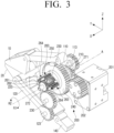
- FIG. 3 is a perspective view of the grip apparatus of FIG. 2 according to an embodiment.
- a grip apparatus 1 may include a first finger 10, a second finger 20, a first link 110, a second link 120, a differential apparatus 200, a third gear 230, and a housing 300.
- the first finger 10 and the second finger 20 may be disposed to face each other and may be spaced apart by a predetermined distance to form a space between which an object to be gripped is disposed.
- the surfaces of the first and second fingers 10 and 20 facing each other may be parallel.
- a spacing between the first and second fingers 10 and 20 may be adjusted as the differential apparatus 200 (described below) drives the first and second links 110 and 120.
- the first link 110 may support the first finger 10.
- the first end 111 of the first link 110 may be connected to the first finger 10, and the second end 112 thereof may be rotatably connected to the housing 300.
- the second link 120 may support the second finger 20.
- the first end 121 of the second link 120 may be connected to the second finger 20, and the second end 122 thereof may be rotatably connected to the housing 300.
- the first and second links 110 and 120 may have a straight shape and may have the same length.
- the first link 110 may include a first gear region 113 at the second end 112 thereof, and the second link 120 may also include a gear region 123 at the second end 122 thereof.
- the gear regions 113 and 123 of the first and second links 110 and 120 may be disposed to be engaged with gears of the differential apparatus 200 to be described later. Accordingly, when the gear regions 113 and 123 of the first and second links 110 and 120 are rotated by the differential apparatus 200, the first and second links 110 and 120 may rotate about the second ends 112 and 122, respectively, so that the spacing between the first and second fingers 10 and 20 may be adjusted.
- the housing 300 may rotatably support the second ends 112 and 122 of the first and second links 110 and 120.
- the first end 111 of the first link 110 may be connected to a first point 11 of the first finger 10, and the first end 121 of the second link 120 may be connected to a first point 21 of the second finger 20.
- the grip apparatus 1 may further include a third link 130 and a fourth link 140.
- the third link 130 may be connected to a second point 12 of the first finger 10, and may be disposed in parallel with the first link 110.
- a distance S1 between the second end 112 of the first link 110 and the second end 132 of the third link 130 may have the same length as a distance D 1 between the first point 11 and the second point 12 of the first finger 10.
- the fourth link 140 may be connected to a second point 22 of the second finger 20, and may be disposed in parallel with the second link 120.
- a distance S2 between the second end 122 of the second link 120 and the second end 142 of the fourth link 140 may have the same length as a distance D2 between the first point 21 and the second point 22 of the second finger 20.
- first and second links 110 and 120 and one region of the first finger 10 have an approximately parallelogram shape as the first and second links 110 and 120, the first finger 10 may maintain a horizontal shape even when the first and second links 110 and 120 rotate.
- the second finger 20 may maintain a horizontal shape even when the third and fourth links 130 and 140 rotate.
- first and third links 110 and 130 and the second and fourth links 120 and 140 may each have a structure of a four-bar linkage.
- the first link 110, the third link 130, the first finger 10, and the housing 300 may have a closed-loop shape in which a total of four contacts are connected.
- the second link 120, the fourth link 140, the second finger 20, and the housing 300 may also have a closed-loop shape in which a total of four contacts are connected.
- the four-bar linkage having the parallelogram shape supports the first and second fingers 10 and 20, respectively, the first and second fingers 10 and 20 may stably grip an object while maintaining a horizontal state.
- the differential apparatus 200 may connect the second end 112 of the first link 110 and the second end 122 of the second link 120, and may include a motor 201.
- the differential apparatus 200 may rotate the first and second links 110 and 120 in different directions when the motor 201 is driven. Accordingly, because the first finger 10 and the second finger 20 move away from or close to each other, the grip apparatus 1 may perform a gripping operation.
- the differential apparatus 200 may also rotate the other of the first and second links 110 and 120 in the first direction.
- the first direction may be an R1 direction or an R2 direction.
- the grip apparatus 1 may not drop the object being gripped and may maintain a gripping force because the first link 110 and the second link 120 rotate in the same direction.
- the differential apparatus 200 may include a first gear 210, a second gear 220, and a third gear 230.
- the first gear 210 may be engaged with the first gear region 113.
- the second gear 220 may be interlocked with the first gear 210 to rotate in the same direction as the first gear 210 or rotate in a direction different from that of the first gear 210.
- the third gear 230 may be engaged with the second gear region 123 and the second gear 220.
- the first gear 210 and the first gear region 113 may have the same width and may be disposed on the same plane (e.g., Y-Z plane).
- the third gear 230, the second gear region 123, and the second gear 220 may have the same width and may be disposed on the same plane (e.g., Y-Z plane).
- first link 110 may rotate in an opposite direction to a rotation direction of the first gear 210
- second link 120 may rotate in the same direction as a rotation direction of the second gear 220 by the third gear 230.
- the first and second gears 210 and 220 of the differential apparatus 200 may rotate in the same direction or may rotate in different directions.
- the first and second gears 210 and 220 may rotate in the same direction. Accordingly, when any one of the first gear 210 or the second gear 220 rotates in one direction by applying an external force to at least one of the first finger 10, the second finger 20, the first link 110, and the second link 120, the other of the first and second gears 210 and 220 may rotate in an opposite direction.
- the differential apparatus 200 may include a ring gear 240 disposed between the first and second gears 210 and 220 and rotated by the motor 201.
- Thedifferential apparatus 200 may further include a pinion 202 that is rotated by the motor 201 and is engaged with the ring gear 240, and when the pinion 202 is rotated by the motor 201, the ring gear 240 may rotate in an opposite direction to the pinion 202.
- the differential apparatus 200 may include a first shaft 271 having a first end supporting the first gear 210 and rotating integrally with the first gear 210, and a second shaft 272 supporting the second gear 220 and rotating integrally with the second gear 220.
- the first and second shafts 271 and 272 may be coaxially disposed, and accordingly, the first and second gears 210 and 220 may coaxially rotate. In addition, the first and second shafts 271 and 272 may be spaced apart from each other and rotate independently from each other.
- the gear region 113 of the first link 110 and the third gear 230 may be disposed on opposite sides with respect to the central axis A of the first and second shafts 271 and 272.
- the gear region 113 of the first link 110 may be disposed on a +Z direction side from the central axis A of the first and second shafts 271 and 272, and the third gear 230 may be disposed on a -Z direction side from the central axis A of the first and second shafts 271 and 272.
- the first shaft 271 may penetrate through the ring gear 240, and may rotate independently without being in contact with the ring gear 240.
- the differential apparatus 200 may further include a side gear 250, a first spider shaft 261, a second spider shaft 262, a first spider gear 263, and a second spider gear 264.
- the side gear 250 may be supported by the first shaft 271 and may rotate integrally with the first shaft 271. That is, the first shaft 271 may support the first gear 210 and the side gear 250 disposed at the first end and the second end thereof, and may rotate integrally with the first gear 210 and the side gear 250.
- the first and second spider shafts 261 and 262 may be disposed in parallel with the first shaft 271 and may rotate integrally with the ring gear 240.
- the first spider shaft 261 and the second spider shaft 262 may be alternately disposed along a circumferential direction of the ring gear 240.
- the first spider gear 263 may be rotatably supported on the first spider shaft 261, and may be disposed to be engaged with the side gear 250.
- the second spider gear 264 may be rotatably supported on the second spider shaft 262, and may be disposed to be engaged with the first spider gear 263 and the second gear 220.
- the first and second spider shafts 261 and 262 formed integrally with the ring gear 240 may also rotate in the same direction as the ring gear 240, and the first and second spider gears 263 and 264 may rotate in the same direction as the ring gear 240 about the central axis A of the first and second shafts 271 and 272 in a state that neither rotates.
- the side gear 250 engaged with the first spider gear 263 may also rotate in the same direction as the ring gear 240, and the first shaft 271 and the first gear 210 formed integrally with the side gear 250 may also rotate in the same direction as the ring gear 240.
- the second gear 220 engaged with the second spider gear 264 may also rotate in the same direction as the ring gear 240.
- both the first and second gears 210 and 220 may rotate in the same direction as the ring gear 240.
- the first shaft 271 and the side gear 220 formed integrally with the first gear 210 may rotate in the same direction as the first gear 210.
- the first spider gear 263 engaged with the side gear 220 may rotate in the opposite direction to the first gear 210 with respect to the first spider shaft 261
- the second spider gear 264 engaged with the first spider gear 263 may rotate in the same direction as the first gear 210 with respect to the second spider shaft 262.
- the second gear 220 engaged with the second spider gear 264 may rotate in an opposite direction to the first gear 210. That is, when the first gear 210 rotates first, the second gear 220 may rotate in the opposite direction to the first gear 220. Conversely, in a case in which the above-described power transmission process is reversed, when the second gear 220 rotates first, the first gear 210 may rotate in an opposite direction to the second gear 210.
- the differential apparatus 200 may rotate the first and second gears 210 and 220 in the same direction when the ring gear 240 is rotated by the motor 201.
- the differential apparatus 200 may rotate the first and second gears 210 and 220 in different directions when an external force is applied to at least one of the first finger 10, the second finger 20, the first link 110, and the second link 120.
- the structure of the differential apparatus 200 described above is implemented as a type of a plurality of spur gears, but is not limited thereto, and may be implemented as a type of a bevel gear.
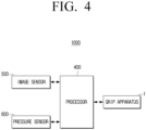
- FIG. 4 is a block diagram of a robot apparatus according to an embodiment.
- a robot apparatus 1000 may include a grip apparatus 1, a processor 400, an image sensor 500, and a pressure sensor 600.
- the grip apparatus 1 may include a first finger 10, a second finger 20, a first link 110 and a second link 120 for supporting the first and second fingers 10 and 20, respectively, a differential apparatus 200 including a first gear 210 engaged with a gear region 113 of the first link 110 and a second gear 220 rotating by being interlocked with the first gear 210, and a third gear 230 engaged with a gear region 123 of the second link 120 and the second gear 220.
- the processor 400 may control an overall operation of the robot apparatus 1000.
- the processor 400 may include a central processing unit (CPU) or an application processor (AP).
- the processor 400 may be implemented as at least one general processor, a digital signal processor, an application specific integrated circuit (ASIC), a system on chip (SoC), a microcomputer (MICOM), a driver integrated circuit (IC), or the like.
- ASIC application specific integrated circuit
- SoC system on chip
- MICOM microcomputer
- IC driver integrated circuit
- the image sensor 500 may detect at least one of a shape and a position of an object.
- the image sensor 500 may be a camera configured to photograph an object around the robot apparatus 1000.
- the image sensor 500 may be implemented as a three dimensional (3D) camera or a depth camera.
- Such an image sensor 500 may be disposed on a body part or a head part of the robot apparatus 1000, but the position is not necessarily limited thereto, and the image sensor 500 may be disposed at various positions such as the first and second links 110 and 120 and the first and second fingers 10 and 20 of the grip apparatus 1.
- the processor 400 may receive information on the shape and position of the object detected by the image sensor 500 and analyze the information to determine the position, size, shape, type, and the like of the object.
- the processor 400 may determine the size, shape, type, and the like, of the object by recognizing the object through an object recognition algorithm, and determine the position of the object based on depth information of the object.
- the image sensor 500 may detect a position and shape of an object to be gripped, and transmit information on the detected position and shape to the processor 400.
- the processor 400 compares the information received from the image sensor 500 with shape information of various objects stored in the memory to determine the type and position of the obj ect.
- the processor 400 may control the grip apparatus 1 to move to a position adjacent to the object to be gripped. Thereafter, the processor 400 may control the grip apparatus so that the first and second fingers 10 and 20 have a spacing corresponding to a thickness of the object detected by the image sensor. In this case, the spacing between the first and second fingers 10 and 20 may be substantially equal to the thickness of the object to be gripped, and the first and second fingers 10 and 20 may easily grip the object.
- the robot apparatus 1000 may further include a pressure sensor 600 that measures a pressure applied to at least one of the first and second fingers 10 and 20.
- the processor 400 may control the operation of the grip apparatus 1 based on a value measured by the pressure sensor 600.
- the pressure sensor 600 may measure a pressure applied to at least one of the first and second fingers 10 and 20.
- the pressure sensor 600 may include a piezoelectric element or a load cell to convert the pressure applied to at least one of the first and second fingers 10 and 20 into an electrical signal and transmit the electrical signal to the processor 400.
- the pressure sensor 600 may be disposed on opposite surfaces of the first and second fingers 10 and 20. Two pressure sensors 600 may be disposed on both the first and second fingers 10 and 20, or one pressure sensor 600 may be disposed on one of the first and second fingers 10 and 20.
- the pressure sensor 600 may detect a pressure applied by the object to the first and second fingers 10 and 20, convert the pressure into an electrical signal, and transmit the electrical signal to the processor 400.
- the grip apparatus 1 may perform a gripping operation by the differential apparatus 200 of the grip apparatus 1.
- the object may apply a pressure to the first and second fingers 10 and 20, and the pressure sensor 600 may detect a value of the pressure.
- the processor 400 may control the gripping operation of the grip apparatus 1 based on the value measured by the pressure sensor 600. When a measured pressure value reaches a critical pressure value by comparing the pressure value measured by the pressure sensor 600 with the critical pressure value stored in the memory, the processor 400 may control to stop driving of the differential apparatus 200 of the grip apparatus 1.
- the robot apparatus 1000 may prevent the problem that the object is damaged by excessive pressure or slips from the grip apparatus 1 by excessively small pressure, and may stably grip the object with an appropriate gripping force.
- FIG. 5 is a perspective view of a grip apparatus in which first and second fingers are moved in opposite directions to be spaced apart from each other according to an embodiment.
- FIG. 6 is a side view of the grip apparatus of FIG. 5 according to an embodiment.
- the R1 direction and the R2 direction indicate the rotation directions on the Y-Z plane of each component, and may be opposite to each other.
- the first and second spider gears 263 and 264 may rotate in the R1 direction with respect to the central axis A of the first and second shafts 271 and 272 together with the first and second spider shafts 261 and 262.
- the side gear 250 engaged with the first spider gear 263 and the first shaft 271 and the first gear 210 formed integrally with the side gear 250 may be rotated in the R2 direction.
- the second gear 220 engaged with the second spider gear 264 may also be rotated in the R2 direction.
- the gear region 113 of the first link 110 engaged with the first gear 210 may be rotated in the R1 direction.
- the third gear 230 engaged with the second gear 220 may be rotated in the R1 direction, and the gear region 123 of the second link 120 engaged with the third gear 230 may be rotated in the R2 direction.
- the first link 110 may be rotated in the R1 direction about the second end 112 thereof, and the second link 120 may be rotated in the R2 direction about the second end 122 thereof. Accordingly, the spacing D between the first and second fingers 10 and 20 may increase.
- the gear region 113 of the first link 110 and the gear region 123 of the second link 120 have the same gear ratio, the first and second links 110 and 120 may be rotated at the same angle.
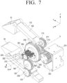
- FIG. 7 is a perspective view of a grip apparatus in which the first and second fingers are moved in the same direction by an external force applied to the grip apparatus according to an embodiment.
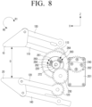
- FIG. 8 is a side view of the grip apparatus of FIG. 7 according to an embodiment.
- an external force in a +Z direction may be applied to at least one of the first and second fingers 10 and 20 and the first to fourth links 110, 120, 130, and 140.
- the second link 120 when the external force in the +Z direction is applied to the second link 120, the second link 120 may be rotated in the R1 direction around the first end 121 thereof. Accordingly, the gear region 123 of the second link 120 may also be rotated in the R1 direction.
- the third gear 230 engaged with the gear region 123 of the second link 120 may be rotated in the R2 direction, and the second gear 220 engaged with the third gear 230 may be rotated in the R1 direction.
- the second spider gear 264 engaged with the second gear 220 may rotate in the R2 direction about the second spider shaft 262, and the first spider gear 263 engaged with the second spider gear 264 may rotate in the R1 direction about the first spider shaft 261.
- the side gear 250 engaged with the first spider gear 263 may be rotated in the R2 direction, and the first shaft 271 and the first gear 210 formed integrally with the side gear 250 may also be rotated in the R2 direction.
- the gear region 113 of the first link 110 engaged with the first gear 210 may be rotated in the R1 direction, and thus the first link 110 may be rotated in the R1 direction about the first end 111 thereof.
- the first link 110 When the second link 120 is rotated in the R1 direction by the external force, the first link 110 may also be rotated in the same R1 direction as the second link 120. That is, because the first and second links 110 and 120 are rotated in the same direction even when the external force is applied to the grip apparatus 1, the grip apparatus 1 may not drop the gripped object and maintain the gripping force.
- the gear region 113 of the first link 110 and the gear region 123 of the second link 120 may have the same gear ratio, and accordingly, because the first and second links 110 and 120 are rotated at the same angle, the spacing D between the first and second fingers 10 and 20 is also maintained, so that the gripped object may not be dropped.
- the grip apparatus 1 may have a passive adaptation mechanism capable of effectively absorbing an impact by flexibly responding to the external force without a separate sensing process or control process.
- first and second links 110 and 120 are not fixed and are rotated in the same direction as the direction of the external force, a user who collides with the grip apparatus 1 may not be injured, or an obstacle that collides with the grip apparatus 1 may not be damaged.
- FIG. 9 is a side view illustrating a state in which the first and second fingers are moved in opposite directions in the grip apparatus of FIG. 7 according to an embodiment.
- the first link 110 may be rotated in the R2 direction about the second end 112 thereof, and the second link 120 may be rotated in the R2 direction about the second end 122 thereof according to the above-described process.
- the first and second fingers 10 and 20 may grip the object at a position different from that of FIG. 2 . That is, the grip apparatus 1 according to an embodiment of the disclosure may not necessarily grip only an object located in the middle, but may grip objects located at various positions along the Z-axis.
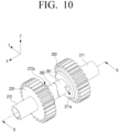
- FIG. 10 is a perspective view of first and second cam members according to an embodiment.
- FIG. 11 is a cross-sectional view of first and second cam members according to an embodiment.
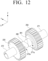
- FIG. 12 is a perspective view illustrating a state in which one of the first and second cam members is twisted according to an embodiment.
- the differential apparatus 200 may include a first cam member 281 and a second cam member 282.
- the first cam member 281 may be connected in parallel to the first shaft 271, and the second cam member 282 may be connected in parallel to the second shaft 272 and in contact with the first cam member 281.
- the first and second shafts 271 and 272 may have key grooves 271a and 272a formed on inner surfaces thereof, and the first and second cam members 281 and 282 may be respectively inserted along the key grooves 271a and 272a formed in the first and second shafts 271 and 272 to be connected to the first and second shafts 271 and 272.
- first and second cam members 281 and 282 may rotate integrally with the first and second shafts 271 and 272, and may relatively move only in the axial direction of the first and second shafts 271 and 272.
- the first and second shafts 271 and 272 are spaced apart from each other, but the first and second cam members 281 and 282 connected thereto may be in contact with each other.
- the first and second cam members 281 and 282 may be disposed along an X axis.
- the first and second cam members 281 and 282 may have concave surfaces 281a and 282a facing each other.
- the surfaces 281a and 282a of the first and second cam members 281 and 282 may have a shape in which an intermediate region thereof is concave, and a portion of a peripheral region thereof protrudes to engage with each other.
- the differential apparatus 200 may further include a bolt 291 and a pressing member 292.
- the bolt 291 may be fixedly disposed inside at least one of the first and second shafts 271 and 272, and the pressing member 292 may connect the bolt 291 to at least one of the first and second cam members 281 and 282.
- the pressing member 292 may be a compression spring that pushes the first cam member 281 or the second cam member 282 from the bolt 291.
- the bolt 291 and the pressing member 292 are illustrated as being disposed inside the first shaft 271, but the positions thereof are not limited thereto.
- the first and second shafts 271 and 272 may not be rotated due to a frictional force acting between the first and second cam members 281 and 282 by the pressing member 292. Accordingly, it is possible to prevent the first and second fingers 10 and 20 being unintentionally moved by a small force such as gravity of the grip apparatus 1 itself.
- the pressing member 292 When an external force of the threshold value or more is applied to the grip apparatus 1, the pressing member 292 is retracted, and the first cam member 281 or the second cam member 282 enters the first shaft 271 or the second shaft 272, respectively. As a result, the first and second cam members 281 and 282 may be twisted and rotated to be spaced apart from each other. Accordingly, in order to prevent the grip apparatus 1 from being unintentionally operated, the external force may be selected by the first and second cam members 281 and 282 and the pressing member 292 which are in contact with each other, and the passive adaptation process described above with reference to FIGS. 7 and 8 may be performed only for the external force of the threshold value or more.
Landscapes
- Engineering & Computer Science (AREA)
- Robotics (AREA)
- Mechanical Engineering (AREA)
- Human Computer Interaction (AREA)
- Health & Medical Sciences (AREA)
- General Health & Medical Sciences (AREA)
- Orthopedic Medicine & Surgery (AREA)
- Multimedia (AREA)
- Manipulator (AREA)
Applications Claiming Priority (3)
| Application Number | Priority Date | Filing Date | Title |
|---|---|---|---|
| KR20200137810 | 2020-10-22 | ||
| KR1020210120643A KR20220053467A (ko) | 2020-10-22 | 2021-09-09 | 그립 장치 및 이를 포함하는 로봇 장치 |
| PCT/KR2021/014687 WO2022086162A1 (fr) | 2020-10-22 | 2021-10-20 | Appareil de préhension et appareil robot le comprenant |
Publications (2)
| Publication Number | Publication Date |
|---|---|
| EP4197717A1 true EP4197717A1 (fr) | 2023-06-21 |
| EP4197717A4 EP4197717A4 (fr) | 2024-03-13 |
Family
ID=81258995
Family Applications (1)
| Application Number | Title | Priority Date | Filing Date |
|---|---|---|---|
| EP21883230.1A Pending EP4197717A4 (fr) | 2020-10-22 | 2021-10-20 | Appareil de préhension et appareil robot le comprenant |
Country Status (2)
| Country | Link |
|---|---|
| US (1) | US12151375B2 (fr) |
| EP (1) | EP4197717A4 (fr) |
Families Citing this family (5)
| Publication number | Priority date | Publication date | Assignee | Title |
|---|---|---|---|---|
| KR102560904B1 (ko) * | 2018-06-14 | 2023-07-27 | 엘지전자 주식회사 | 포터 모듈이 구비된 모듈형 이동 로봇 |
| KR102331633B1 (ko) * | 2020-02-18 | 2021-11-25 | 한양대학교 에리카산학협력단 | 로봇 그리퍼 |
| US11826910B2 (en) * | 2021-05-20 | 2023-11-28 | Carnegie Mellon University | Direct drive end-effectors with parallel kinematics |
| EP4559640A4 (fr) * | 2023-02-15 | 2025-08-06 | Samsung Electronics Co Ltd | Main robotique et son procédé de commande |
| CN119050893B (zh) * | 2024-11-01 | 2025-01-24 | 四川兴济电力科技有限公司 | 一种输配电线路运维检修装置及方法 |
Family Cites Families (24)
| Publication number | Priority date | Publication date | Assignee | Title |
|---|---|---|---|---|
| JPS6025686A (ja) * | 1983-07-20 | 1985-02-08 | 株式会社東芝 | ロボツトハンド |
| KR100236739B1 (ko) | 1997-12-23 | 2000-04-01 | 이종훈 | 연속회전이 가능한 로봇 그리퍼 |
| JP4270660B2 (ja) | 1999-07-22 | 2009-06-03 | ファミリー株式会社 | ハンド型マッサージ機及び椅子型マッサージ装置 |
| JP2005230999A (ja) * | 2004-02-20 | 2005-09-02 | Japan Servo Co Ltd | 把持装置 |
| JP4591043B2 (ja) * | 2004-11-02 | 2010-12-01 | トヨタ自動車株式会社 | ロボットによる任意形状物体の把持方法 |
| JP5082037B2 (ja) * | 2006-08-28 | 2012-11-28 | 国立大学法人九州工業大学 | ロボットハンド |
| JP5086778B2 (ja) | 2007-11-26 | 2012-11-28 | トヨタ自動車株式会社 | ロボットアーム |
| JP5195054B2 (ja) | 2008-06-11 | 2013-05-08 | パナソニック株式会社 | アームの関節、及びそれを有するロボット |
| EP2380713B1 (fr) * | 2008-12-04 | 2015-05-20 | Kawasaki Jukogyo Kabushiki Kaisha | Main de robot |
| JP2012166297A (ja) * | 2011-02-14 | 2012-09-06 | Seiko Epson Corp | ロボットハンド及びロボット装置 |
| CA2856622C (fr) * | 2011-11-25 | 2017-01-10 | Robotiq Inc. | Appareil de prehension comprenant un doigt mecanique sous-actionne a deux degres de liberte permettant la prehension par enserrage et par pincement |
| JP5690318B2 (ja) * | 2012-11-14 | 2015-03-25 | Thk株式会社 | ロボットハンド |
| KR101444386B1 (ko) | 2013-03-06 | 2014-09-26 | 삼성중공업 주식회사 | 로봇 핸드의 다중 링크 핑거 모듈 |
| US9314934B2 (en) | 2014-02-27 | 2016-04-19 | Disney Enterprises, Inc. | Gravity-counterbalanced robot arm |
| US10046461B2 (en) | 2014-08-25 | 2018-08-14 | Paul Ekas | Link structure and assembly including cable guide system for robotic mechanical manipulator structure |
| JP6444942B2 (ja) | 2016-05-26 | 2018-12-26 | ファナック株式会社 | 衝撃緩和部材を有するツールを備えたロボット |
| US9782902B1 (en) | 2016-06-29 | 2017-10-10 | Robotis Co., Ltd. | Gripper for robot hand capabel of adaptive grasp |
| CN106078781B (zh) * | 2016-08-05 | 2018-11-30 | 广州市轻工职业学校 | 连杆带轮直线平夹感知自适应机器人手指装置 |
| IT201600120646A1 (it) * | 2016-11-29 | 2018-05-29 | Giovanni Antonio Zappatore | Mano robotica sottoattuata |
| KR102001101B1 (ko) | 2017-08-25 | 2019-07-18 | 주식회사 토룩 | 로봇 제어 시스템 |
| CN111283707B (zh) | 2020-02-28 | 2022-08-19 | 安徽大学 | 一种刚柔融合的两指自适应机械手 |
| WO2022003727A1 (fr) * | 2020-07-01 | 2022-01-06 | INDIAN INSTITUTE OF TECHNOLOGY MADRAS (IIT Madras) | Dispositif de préhension robotique à rigidité variable fondé sur un mécanisme docile |
| JP7612425B2 (ja) * | 2021-01-14 | 2025-01-14 | 株式会社東芝 | 保持装置および搬送装置 |
| JP7558819B2 (ja) * | 2021-01-14 | 2024-10-01 | 株式会社東芝 | 保持装置、搬送装置、および保持装置の制御方法 |
-
2021
- 2021-10-20 EP EP21883230.1A patent/EP4197717A4/fr active Pending
- 2021-12-08 US US17/545,532 patent/US12151375B2/en active Active
Also Published As
| Publication number | Publication date |
|---|---|
| US12151375B2 (en) | 2024-11-26 |
| CN116348259A (zh) | 2023-06-27 |
| US20220126443A1 (en) | 2022-04-28 |
| EP4197717A4 (fr) | 2024-03-13 |
Similar Documents
| Publication | Publication Date | Title |
|---|---|---|
| EP4197717A1 (fr) | Appareil de préhension et appareil robot le comprenant | |
| KR20220053467A (ko) | 그립 장치 및 이를 포함하는 로봇 장치 | |
| US8380351B2 (en) | Manipulator, manipulator collision detecting method and manipulator control method | |
| US9925672B2 (en) | Robot gripping device | |
| JP2020114623A (ja) | 産業用ロボットとこれの安全制御を与える方法 | |
| CN112008715B (zh) | 机器人系统 | |
| EP2853359B1 (fr) | Robot | |
| US20150028613A1 (en) | Robot gripping device | |
| CN101848687B (zh) | 转动调整装置及转动装置的控制方法 | |
| CN103934833B (zh) | 机器人装置 | |
| US20140148951A1 (en) | Manipulator device | |
| US9364952B2 (en) | Force sensor protection mechanism, end effector, and robot arm | |
| CN103963075B (zh) | 机器人系统 | |
| von Drigalski et al. | A compact, cable-driven, activatable soft wrist with six degrees of freedom for assembly tasks | |
| CN110744539B (zh) | 机器人、控制装置以及控制方法 | |
| KR100987087B1 (ko) | 항복 토크 발생장치 및 이를 이용한 회전기구 | |
| US20110230868A1 (en) | Remote-controlled actuator | |
| JP2017127908A (ja) | ロボットが出力する回転力を用いるねじ締め装置 | |
| KR20120091940A (ko) | 토크 센싱 및 감속 기능 구비 캠 기반 통합 안전 관절 유니트 | |
| EP2607028A2 (fr) | Outil électrique | |
| US11668375B2 (en) | Parallel link mechanism and link actuation device | |
| KR102076907B1 (ko) | 로봇 매니퓰레이터 | |
| Ergun et al. | A unified perception benchmark for capacitive proximity sensing towards safe human-robot collaboration (HRC) | |
| KR102479330B1 (ko) | 로봇 충돌 감지 시스템 및 방법 | |
| JP2021159999A (ja) | 複数の指を有するロボットハンドの駆動機構 |
Legal Events
| Date | Code | Title | Description |
|---|---|---|---|
| STAA | Information on the status of an ep patent application or granted ep patent |
Free format text: STATUS: THE INTERNATIONAL PUBLICATION HAS BEEN MADE |
|
| PUAI | Public reference made under article 153(3) epc to a published international application that has entered the european phase |
Free format text: ORIGINAL CODE: 0009012 |
|
| STAA | Information on the status of an ep patent application or granted ep patent |
Free format text: STATUS: REQUEST FOR EXAMINATION WAS MADE |
|
| 17P | Request for examination filed |
Effective date: 20230315 |
|
| AK | Designated contracting states |
Kind code of ref document: A1 Designated state(s): AL AT BE BG CH CY CZ DE DK EE ES FI FR GB GR HR HU IE IS IT LI LT LU LV MC MK MT NL NO PL PT RO RS SE SI SK SM TR |
|
| DAV | Request for validation of the european patent (deleted) | ||
| DAX | Request for extension of the european patent (deleted) | ||
| A4 | Supplementary search report drawn up and despatched |
Effective date: 20240213 |
|
| RIC1 | Information provided on ipc code assigned before grant |
Ipc: B25J 19/02 20060101ALI20240207BHEP Ipc: B25J 9/16 20060101ALI20240207BHEP Ipc: B25J 15/02 20060101AFI20240207BHEP |