EP4197723B1 - Klinge einer haarschneidemaschine und haarschneidemaschine - Google Patents
Klinge einer haarschneidemaschine und haarschneidemaschine Download PDFInfo
- Publication number
- EP4197723B1 EP4197723B1 EP22211071.0A EP22211071A EP4197723B1 EP 4197723 B1 EP4197723 B1 EP 4197723B1 EP 22211071 A EP22211071 A EP 22211071A EP 4197723 B1 EP4197723 B1 EP 4197723B1
- Authority
- EP
- European Patent Office
- Prior art keywords
- blade
- fixed blade
- exemplary embodiment
- contact surface
- distal end
- Prior art date
- Legal status (The legal status is an assumption and is not a legal conclusion. Google has not performed a legal analysis and makes no representation as to the accuracy of the status listed.)
- Active
Links
Images







Classifications
-
- B—PERFORMING OPERATIONS; TRANSPORTING
- B26—HAND CUTTING TOOLS; CUTTING; SEVERING
- B26B—HAND-HELD CUTTING TOOLS NOT OTHERWISE PROVIDED FOR
- B26B19/00—Clippers or shavers operating with a plurality of cutting edges, e.g. hair clippers, dry shavers
- B26B19/02—Clippers or shavers operating with a plurality of cutting edges, e.g. hair clippers, dry shavers of the reciprocating-cutter type
- B26B19/04—Cutting heads therefor; Cutters therefor; Securing equipment thereof
- B26B19/06—Cutting heads therefor; Cutters therefor; Securing equipment thereof involving co-operating cutting elements both of which have shearing teeth
- B26B19/063—Movable or adjustable cutting head
-
- B—PERFORMING OPERATIONS; TRANSPORTING
- B26—HAND CUTTING TOOLS; CUTTING; SEVERING
- B26B—HAND-HELD CUTTING TOOLS NOT OTHERWISE PROVIDED FOR
- B26B19/00—Clippers or shavers operating with a plurality of cutting edges, e.g. hair clippers, dry shavers
- B26B19/02—Clippers or shavers operating with a plurality of cutting edges, e.g. hair clippers, dry shavers of the reciprocating-cutter type
- B26B19/04—Cutting heads therefor; Cutters therefor; Securing equipment thereof
- B26B19/06—Cutting heads therefor; Cutters therefor; Securing equipment thereof involving co-operating cutting elements both of which have shearing teeth
-
- B—PERFORMING OPERATIONS; TRANSPORTING
- B26—HAND CUTTING TOOLS; CUTTING; SEVERING
- B26B—HAND-HELD CUTTING TOOLS NOT OTHERWISE PROVIDED FOR
- B26B19/00—Clippers or shavers operating with a plurality of cutting edges, e.g. hair clippers, dry shavers
- B26B19/38—Details of, or accessories for, hair clippers, or dry shavers, e.g. housings, casings, grips, guards
- B26B19/3846—Blades; Cutters
-
- B—PERFORMING OPERATIONS; TRANSPORTING
- B26—HAND CUTTING TOOLS; CUTTING; SEVERING
- B26B—HAND-HELD CUTTING TOOLS NOT OTHERWISE PROVIDED FOR
- B26B19/00—Clippers or shavers operating with a plurality of cutting edges, e.g. hair clippers, dry shavers
- B26B19/20—Clippers or shavers operating with a plurality of cutting edges, e.g. hair clippers, dry shavers with provision for shearing hair of preselected or variable length
- B26B19/205—Clippers or shavers operating with a plurality of cutting edges, e.g. hair clippers, dry shavers with provision for shearing hair of preselected or variable length by adjustment of the cutting members
Definitions
- a hair clipper as described in the preamble of claim 1 is already known from CN 201432 312 Y .
- EP 2 926 959 A1 refers to a hair clipper, a head unit of the same and a movable blade of the same.
- a hair clipper capable of adjusting the cutting height
- a blade of a hair clipper and a hair clipper capable of setting a cutting height to be shorter while further reducing stimulation applied to the skin during use.
- a side on which a switch unit is provided is defined as a front face.
- main body 11 includes housing 12 forming a substantially S-shaped outer shell in a side view.
- Housing 12 can be formed using, for example, a material such as a synthetic resin, and is attached to a front face of housing 12 such that operation switch 12a can be pushed inward in a state of being exposed to an outside.
- controller 17 and the like that control power supply to electric motor 14 according to a pressing operation of operation switch 12a exposed to the outside are accommodated in the cavity formed inside housing 12.
- Fig. 4 is a perspective view illustrating an example of blade block 40 included in hair clipper 10 according to the exemplary embodiment.
- Fig. 5 is a plan view illustrating an example of blade block 40 included in hair clipper 10 according to the exemplary embodiment.
- Fig. 6 is a bottom view illustrating an example of blade block 40 included in hair clipper 10 according to the exemplary embodiment.
- Fig. 7 is a side view illustrating an example of blade block 40 included in hair clipper 10 according to the exemplary embodiment.
- Blade block 40 has a function of cutting hair, and as illustrated in Figs. 4 to 7 , includes blade part 45 (that is, a blade of hair clipper 10) formed by disposing movable blade 46 and fixed blade 47 so as to face each other.
- Blade part 45 is configured such that movable blade bar 462 (see Fig. 8 ), which will be described later, of movable blade 46 reciprocally slides in width direction Y with respect to fixed blade bar 472, which will be described later, of fixed blade 47.
- Fig. 8 is an exploded perspective view illustrating an example of blade block 40 included in hair clipper 10 according to the exemplary embodiment.
- blade block 40 further includes fixing plate 41 made of resin on which blade part 45 is disposed, and guide plate 42 made of resin and fixed to movable blade 46.
- blade block 40 includes metallic push-up spring 43 that presses movable blade 46 toward fixed blade 47, and resinous switching lever 44 that holds push-up spring 43.
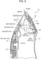
- Fig. 9 is a view illustrating an example of a cutting height adjustment mechanism included in hair clipper 10 according to the exemplary embodiment, and is a sectional view illustrating a state in which a cutting height is maximized.
- fixing plate 41 is a member fixed to main body 11 in a state where fixed blade 47 is fixed, and includes hook part 41a for engaging with main body 11, insertion groove 41b for inserting and holding insertion protrusion 4711 of fixed blades 47, and holding groove 41c that opens upward.
- Columnar part 44a, which will be described later, of switching lever 44 is inserted and held in holding groove 41c in a state of being relatively rotatable with respect to fixing plate 41.
- Push-up spring 43 is a member that presses movable blade 46 toward fixed blade 47 to more reliably bring movable blade bar 462 and fixed blade bar 472, both of which will be described later, into sliding contact with each other, and can be formed by, for example, a torsion spring.
- push-up spring 43 includes a pair of coil parts 43a held by switching lever 44 and connecting part 43b held by switching lever 44 and connecting the pair of coil parts 43a.
- push-up spring 43 includes arm part 43c that is connected to an opposite side of connection part 43b of each coil part 43a, is fixed to movable blade 46, and presses movable blade 46 toward fixed blade 47.
- hair clipper 10 is configured to change a cutting height of hair without using the attachment, and as illustrated in Figs. 1 to 3 , main body 11 includes cutting height adjustment mechanism 20.
- cutting height adjustment mechanism 20 By operating cutting height adjustment mechanism 20, a tilting operation of switching lever 44 is performed, and the cutting height of the hair is changed by the tilting operation of switching lever 44.
- switching lever 44 includes columnar part 44a that is inserted and held in holding groove 41c of fixing plate 41 in a state of being relatively rotatable with respect to fixing plate 41. Furthermore, switching lever 44 includes accommodating recess 44b in which coil part 43a of push-up spring 43 is accommodated in a fitted state, and accommodating recess 44c in which a connecting part of push-up spring 43 is accommodated. Moreover, switching lever 44 includes protruding part 44d operated by transmission mechanism 22. Switching lever 44 is held by fixing plate 41 in a state of being biased toward a side of the falling attitude by push-up spring 43.
- cutting height adjustment mechanism 20 includes dial 21 for cutting height adjustment rotatably attached to main body 11, and transmission mechanism 22 that performs the tilting operation of switching lever 44 of blade block 40 in conjunction with the rotation of dial 21.
- dial 21 for adjusting a cutting height is provided closer to blade block 40 (that is, the upper side of Fig. 1 ) than operation switch 12a on the front side of housing 12 so as to be rotatable relative to housing 12.
- dial 21 can be relatively rotated with respect to housing 12 about rotation axis C1 extending in a left-right direction (that is, one type of horizontal direction) in the state illustrated in Fig. 9 .
- Transmission mechanism 22 is accommodated in the cavity formed inside housing 12, and includes first conversion mechanism 221 and second conversion mechanism 222.
- first conversion mechanism 221 is a mechanism that converts the rotation (that is, reciprocating rotational motion) of dial 21 about rotation axis C1 into a reciprocating linear motion of dial 21 in a radial direction (that is, a vertical direction in the state illustrated in Fig. 9 ), and includes groove 2211.
- groove 2211 is formed inside dial 21, and has a curved shape such that a distance from rotation axis C1 decreases from one end 2211a toward other end 2211b.
- first conversion mechanism 221 includes rod 2212 having pin 22121 movably inserted into groove 2211, and slider 2213 provided at a distal end of rod 2212.
- pin 22121 moves in groove 2211 in conjunction with the rotation of dial 21.
- rod 2212 and slider 2213 reciprocate linearly in the radial direction (that is, the vertical direction in the state illustrated in Fig. 9 ) of dial 21 in conjunction with the movement of pin 22121 in groove 2211.
- second conversion mechanism 222 is a mechanism that converts the reciprocating linear motion converted by first conversion mechanism 221 into rotation (that is, reciprocating rotational motion) about a rotation axis extending in width direction Y (that is, one direction), and includes operation shaft 2221.
- Operation shaft 2221 is attached to hook part 22131 provided in slider 2213 in a state of extending in width direction Y (that is, one direction), and reciprocates linearly in the radial direction (that is, the vertical direction in the state illustrated in Fig. 9 ) of dial 21 together with slider 2213.
- second conversion mechanism 222 includes rotary member 2222 having one end connected to operation shaft 2221, and rotary shaft 2223 extending in width direction Y (that is, one direction) and to which rotary member 2222 is rotatably attached.
- a pair of rotary members 2222 is provided continuously at both ends in width direction Y (that is, one direction) of operation shaft 2221.
- second conversion mechanism 222 includes action member 2224 that is connected to the other end of rotary member 2222 and performs the tilting operation of switching lever 44, and connecting shaft 2225 that extends in width direction Y (that is, one direction) and connects rotary member 2222 and action member 2224.
- movable blade 46 slides on tapered part 4721 (see Fig. 13 ) of fixed blade 47, which will be described later. That is, in the present exemplary embodiment, movable blade 46 is slid between the root side and the distal end side on tapered part 4721 of fixed blade 47. In this way, the cutting height of the hair is changed.
- protruding part 44d comes into contact with hook part 41a of fixing plate 41 to restrict further standing. That is, by bringing protruding part 44d into contact with hook part 41a of fixing plate 41 to regulate further standing of switching lever 44, sliding of movable blade 46 toward the distal end side is regulated. Furthermore, in the present exemplary embodiment, when switching lever 44 is at the initial position, movable blade 46 is located closest to the root side of fixed blade 47 (that is, a state in which the cutting height is set to be the highest). When the standing of switching lever 44 is regulated by protruding part 44d, movable blade 46 is located closest to the distal end side of fixed blade 47 (that is, a state in which the cutting height is set to be the shortest).
- movable blade 46 includes main body 461, a plurality of movable blade bars 462 arranged side by side in width direction Y on one end side (that is, the front side in front-back direction X) of main body 461, and a plurality of movable blade grooves 463, each of which is formed between adjacent movable blade bars 462.
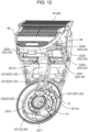
- Fig. 15 is a perspective view illustrating a positional relationship between movable blade 46 and fixed blade 47 when a maximum cutting height is set.
- Fig. 16 is a side view illustrating a positional relationship between movable blade 46 and fixed blade 47 when a maximum cutting height is set.
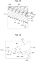
- Fig. 17 is a perspective view illustrating a positional relationship between movable blade 46 and fixed blade 47 when a minimum cutting height is set.
- Fig. 18 is a side view illustrating a positional relationship between movable blade 46 and fixed blade 47 when a minimum cutting height is set.
- Fig. 19 is an enlarged side view illustrating a distal end part of fixed blade 47 included in blade block 40 according to the exemplary embodiment.
- edge 46231 (see Figs. 15 and 17 ) is formed on each side in width direction Y of the cutting part 4623, and the hair can be more reliably cut by edge 46231.
- a surface of distal end 4624 of movable blade bar 462 opposite to sliding contact surface P1 is rounded. That is, curved part 46241 is formed on a surface of distal end 4624 of movable blade bar 462 opposite to sliding contact surface P1. In this way, it is possible to reduce the stimulation applied to the skin by blade part 45 when the side of movable blade 46 is used in contact with the skin.
- each of fixed blade bars 472 has tapered part 4721 that tapers toward a distal end side (that is, the front side in front-back direction X).
- fixed blade 47 includes sliding contact surface P2 (see Figs. 15 to 19 ) with which movable blade 46 can come into sliding contact, and skin contact surface P3 (see Figures 16 , 18 and 19 ) with which skin can come into contact.
- fixed blade bar 472 In side view of fixed blade bar 472 (that is, fixed blade 47 is viewed along width direction Y), skin contact surface P3 is inclined with respect to sliding contact surface P2 such that a distance between skin contact surface P3 and sliding contact surface P2 becomes shorter on the distal end side (that is, the front side in front-back direction X). Accordingly, fixed blade bar 472 is formed with tapered part 4721 having thickness T1 that gradually decreases from the root side toward the distal end side.
- the hair can be cut to a length of 0.3 mm.
- a distal end of tapered part 4721 may come into contact with skin (for example, scalp) during use of hair clipper 10, thereby giving a large stimulus to the skin (for example, scalp).
- fixed blade bar 472 has distal end part 473 on one end side (that is, the front side in front-back direction X) of tapered part 4721.
- Distal end part 473 has uniform part 4731 having a uniform thickness in vertical direction Z (that is, a thickness direction intersecting width direction Y and front-back direction X).
- uniform part 4731 is formed so as to protrude toward skin contact surface P3 (that is, at least one surface of sliding contact surface P2 and skin contact surface P3). That is, uniform part 4731 is formed so as to protrude only toward skin contact surface P3 out of sliding contact surface P2 and skin contact surface P3.
- sliding contact surface P2 can be made a flat surface, and movable blade 46 can be prevented from interfering with uniform part 4731 when movable blade 46 is slid on sliding contact surface P2.
- curved part 4731a is formed at the distal end of fixed blade 47.
- curved part 4731a protruding upward toward the distal end is formed at an upper part of a distal end of uniform part 4731, whereby curved part 4731a is formed at the distal end of fixed blade 47.
- fixed blade 47 is formed such that the distal end forms uniform part 4731, and skin contact surface P4 and distal end surface P5 of uniform part 4731 are connected by curved part 4731a having an R shape.
- uniform part 4731 has a linear part (that is, a flat part).
- length L2 of uniform part 4731 in front-back direction X is set to about 0.4 mm.
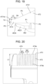
- Fig. 20 is an enlarged bottom view illustrating fixed blade bars 472 and fixed blade grooves 474 of fixed blade 47 according to the exemplary embodiment.
- each fixed blade groove 474 of fixed blade 47 has different widths W2 in width direction Y between distal end side 474a and back side 474b in front-back direction X.
- width W2 of fixed blade groove 474 in width direction Y is gradually reduced from distal end side 474a toward back side 474b.
- width W2 of fixed blade groove 474 in width direction Y is 0.5 mm on distal end side 474a and 0.45 mm on back side 474b.
- width W1 of each fixed blade bar 472 on the root side can be increased.
- width W1 of fixed blade bar 472 in width direction Y is 0.4 mm on distal end side 474a and 0.45 mm on back side 474b.
- width W2 of fixed blade groove 474 in width direction Y can be made gradually wider from distal end side 474a toward back side 474b. Thus, the hair can be more reliably introduced to back side 474b.
- a length from the distal end of fixed blade 47 (that is, the distal end of uniform part 4731) to the distal end of movable blade 46 on sliding contact surface P2 is set to a length of about 0.4 mm to 3.4 mm. In this way, hair can be cut within a movable range of movable blade 46 in front-back direction X.
- width W1 of one fixed blade bar 472 in width direction Y and width W2 of one fixed blade groove 474 in width direction Y ranges from 0.5 mm to 1.0 mm (inclusive). Under such conditions, width W2 of one fixed blade groove 474 in width direction Y is set to 0.3 mm or more.
- width W2 of fixed blade groove 474 in width direction Y is set to such a size that introduction of hair is not hindered. For example, when a thickness of hair is about 0.1 mm, by setting width W2 of fixed blade groove 474 in width direction Y to 0.3 mm or more, at least two or three hairs can be introduced into fixed blade groove 474.
- width W1 of one fixed blade bar 472 in width direction Y when the sum of width W1 of one fixed blade bar 472 in width direction Y and width W2 of one fixed blade groove 474 in width direction Y is 0.5 mm or more and 1.0 mm or less, width W1 of one fixed blade bar 472 in width direction Y can be set to 0.2 mm at minimum. As a result, width W1 of fixed blade bar 472 in width direction Y is prevented from becoming too thin, and a contact area of fixed blade bar 472 with the skin can be prevented from becoming small.
- fixed blade bars 472 and fixed blade grooves 474 satisfy the above relationship, it is possible to simultaneously achieve improvement in hair introducibility, securing strength of fixed blade 47, and securing the number of blades (that is, the number of fixed blade bars 472) of fixed blade 47.
- Blade 45 of the hair clipper described in the exemplary embodiment and the modification examples of the exemplary embodiment includes fixed blade 47, and movable blade 46 that can cut hair by reciprocating sliding in one direction with respect to fixed blade 47.
- fixed blade 47 also include sliding contact surface P2 on which movable blade 46 can slide, and skin contact surface P3 that can come into contact with skin.
- skin contact surface P3 is inclined with respect to sliding contact surface P2 such that a distance between skin contact surface P3 and sliding contact surface P2 becomes short on a distal end side
- movable blade 46 is configured to be slidable on sliding contact surface P2 of fixed blade 47 in an intersecting direction intersecting the one direction.
- Distal end part 473 of fixed blade 47 includes uniform part 4731 having a uniform thickness in a thickness direction intersecting the one direction and the intersecting direction.
- Uniform part 4731 may protrude toward at least one of sliding contact surface P2 and skin contact surface P3.
- the protrusion on sliding contact surface P2 of uniform part 4731 can prevent movable blade 46 from excessively sliding toward the distal end when sliding on sliding contact surface P2.
- skin contact surface P3 can be a flat surface, the skin slippage can be further improved.
- sliding contact surface P2 can be a flat surface, so that movable blade 46 can be prevented from interfering with uniform part 4731 when movable blade 46 is slid on sliding contact surface P2.
- curved part 4731a may be formed at the distal end of fixed blade 47.
- Length L2 of uniform part 4731 in the intersecting direction may be larger than thickness T2 in the thickness direction.
- uniform part 4731 can be configured to have a straight part (that is, the flat part). As a result, it is possible to prevent movable blade 46 from excessively sliding on sliding contact surface P2 while improving skin contact of fixed blade 47.
- the movable blade 46 When movable blade 46 is slid in the intersecting direction, the movable blade may face uniform part 4731 in the thickness direction.
- the cutting height can be made constant. As a result, the accuracy of the shortest cutting height can be further improved.
- fixed blade 47 includes a plurality of fixed blade bars 472 that protrude in the intersecting direction and are arranged side by side in the one direction, and fixed blade grooves 474 provided between fixed blade bars 472 adjacent to each other.
- width W2 in the one direction is different between distal end side 474a and back side 474b in the intersecting direction.
- width W2 of distal end side 474a is wider than width W2 of back side 474b, width W1 of root side of fixed blade bar 472 can be increased, so that strength of fixed blade bar 472 can be further improved.
- width W2 of the distal end side 474a is narrower than width W2 of back side 474b, the hair can be more reliably introduced to the back side.
- width W2 of fixed blade groove 474 in the one direction can be set to such a size that hair introduction is not hindered.
- fixed blade bar 472 can be prevented from being reduced in contact area with skin, and fixed blade groove 474 can be prevented from being excessively increased in width W2 in the one direction. As a result, it is possible to suppress the skin from biting into fixed blade groove 474 too much at the time of use.
- width W1 of fixed blade bar 472 in the one direction and width W2 of fixed blade groove 474 in the one direction are set as described above, a contact area of fixed blade bar 472 with a skin can be prevented from being reduced without hindering hair from being introduced into fixed blade groove 474. As a result, it is possible to provide blade 45 of the hair clipper that is easy to use while improving safety.
- blade 45 of the hair clipper described in the exemplary embodiment and the modification examples of the exemplary embodiment is advantageous in that hair introducibility can be improved, the strength of fixed blade 47 can be secured, and the number of blades (that is, the number of fixed blade bars 472) of fixed blade 47 can be secured at the same time.
- hair clipper 10 described in the exemplary embodiment and the modification examples of the exemplary embodiment includes blade 45 of the hair clipper described above.
- width W2 of fixed blade groove 474 in width direction Y is gradually narrowed from distal end side 474a toward back side 474b.
- a step may be formed in the middle from distal end side 474a to back side 474b.
Landscapes
- Life Sciences & Earth Sciences (AREA)
- Forests & Forestry (AREA)
- Engineering & Computer Science (AREA)
- Mechanical Engineering (AREA)
- Dry Shavers And Clippers (AREA)
Claims (7)
- Klinge (45) einer Haarschneidemaschine (10), die umfasst:eine stationäre Klinge (47); sowieeine bewegliche Klinge (46), die zum Schneiden von Haaren durch Hin-und-Herbewegen sowie Gleiten in Bezug auf die stationäre Klinge (47) in einer Richtung (Y) ausgeführt ist,wobeidie stationäre Klinge (47) eine Gleitkontakt-Fläche (P2) umfasst und die bewegliche Klinge (46) so ausgeführt ist, dass sie daran entlang gleitet, und sie eine Hautkontakt-Fläche (P3) umfasst, die so ausgeführt ist, dass sie mit der Haut in Kontakt kommt,die Hautkontakt-Fläche (P3), bei Sicht auf die stationäre Klinge (47) in der einen Richtung (Y), in Bezug auf die Gleitkontakt-Fläche (P2) so geneigt ist, dass ein Abstand zwischen der Hautkontakt-Fläche (P3) und der Gleitkontakt-Fläche (P2) in Richtung der Seite eines distalen Endes der stationären Klinge (47) verringert wird,die bewegliche Klinge (46) so ausgeführt ist, dass sie an der Gleitkontakt-Fläche (P3) der stationären Klinge (47) in einer Schnittrichtung (X) gleiten kann, die die eine Richtung (Y) schneidet,die stationäre Klinge (47) einen distalen Endteil (473) enthält, der einen einheitlichen Teil (4731) mit einer einheitlichen Dicke in einer Dickenrichtung (Z) enthält, die die eine Richtung (Y) und die Schnittrichtung (X) schneidet, unddie stationäre Klinge (47) des Weiteren umfasst:eine Vielzahl von Zähnen (472) der stationären Klinge, sowieeine Vielzahl von Nuten (474) der stationären Klinge,wobei die Vielzahl von Zähnen (472) der stationären Klinge in der Schnittrichtung (X) vorstehen und in der einen Richtung (Y) nebeneinander angeordnet sind,jede der Vielzahl von Nuten (474) der stationären Klinge zwischen zwei der Vielzahl von Zähnen (472) der stationären Klinge vorhanden sind, die in der Vielzahl von Zähnen (472) der stationären Klinge enthalten sind, und aneinander angrenzen, undjede der Vielzahl von Nuten (474) der stationären Klinge einen Breitenunterschied in der einen Richtung (Y) zwischen einer Seite des distalen Endes und einer hinteren Seite in der Schnittrichtung (X) aufweist,dadurch gekennzeichnet, dassdie stationäre Klinge (47) so ausgebildet ist, dass eine Summe einer Breite (W1) einer der Vielzahl von Zähnen (472) der stationären Klinge in der einen Richtung (Y) und einer Breite (W2) einer der Vielzahl von Nuten (474) der stationären Klinge in der einen Richtung (Y) 0,5 mm oder mehr und 1,0 mm oder weniger beträgt, unddie Breite (W2) der einen der Vielzahl von Nuten (474) der stationären Klinge in der einen Richtung (Y) 0,3 mm oder mehr beträgt.
- Klinge (45) nach Anspruch 1, wobei die bewegliche Klinge (46) so ausgeführt ist, dass sie in der Schnittrichtung (X) schrittweise verschoben werden kann.
- Klinge (45) nach Anspruch 1 oder 2, wobei der einheitliche Teil (4731) auf wenigstens eine Fläche zu vorsteht, die aus der Gruppe ausgewählt wird, die aus der Gleitkontakt-Fläche (P2) und der Hautkontakt-Fläche (P3) besteht.
- Klinge (45) nach einem der Ansprüche 1 bis 3, wobei die stationäre Klinge (47) ein distales Ende umfasst, an dem ein gekrümmter Teil (4731a) ausgebildet ist.
- Klinge (45) nach einem der Ansprüche 1 bis 4, wobei der einheitliche Teil (4731) eine Länge (L2) in der Schnittrichtung (X) hat, die größer ist als eine Dicke (T2) in der Dickenrichtung (Z).
- Klinge (45) nach einem der Ansprüche 1 bis 5, wobei die bewegliche Klinge (46) so ausgeführt ist, dass sie dem einheitlichen Teil (4731) in der Dickenrichtung (Z) zugewandt ist, wenn sie in der Schnittrichtung (X) verschoben wird.
- Haarschneidemaschine (10), die die Klinge (45) nach einem der Ansprüche 1 bis 6 umfasst.
Applications Claiming Priority (1)
| Application Number | Priority Date | Filing Date | Title |
|---|---|---|---|
| JP2021197776A JP7825172B2 (ja) | 2021-12-06 | 2021-12-06 | バリカンの刃およびバリカン |
Publications (2)
| Publication Number | Publication Date |
|---|---|
| EP4197723A1 EP4197723A1 (de) | 2023-06-21 |
| EP4197723B1 true EP4197723B1 (de) | 2025-07-09 |
Family
ID=84387684
Family Applications (1)
| Application Number | Title | Priority Date | Filing Date |
|---|---|---|---|
| EP22211071.0A Active EP4197723B1 (de) | 2021-12-06 | 2022-12-02 | Klinge einer haarschneidemaschine und haarschneidemaschine |
Country Status (5)
| Country | Link |
|---|---|
| US (1) | US20230173698A1 (de) |
| EP (1) | EP4197723B1 (de) |
| JP (1) | JP7825172B2 (de) |
| KR (1) | KR20230085086A (de) |
| CN (1) | CN116214587A (de) |
Families Citing this family (7)
| Publication number | Priority date | Publication date | Assignee | Title |
|---|---|---|---|---|
| USD1035151S1 (en) * | 2022-12-21 | 2024-07-09 | Ningbo VGR Electric Appliance Co., Ltd. | Hair clipper |
| USD1035150S1 (en) * | 2023-01-17 | 2024-07-09 | Ningbo VGR Electric Appliance Co., Ltd. | Hair clipper |
| USD1001374S1 (en) * | 2023-03-13 | 2023-10-10 | Chengjiang Gao | Hair trimmer |
| USD1000707S1 (en) * | 2023-04-03 | 2023-10-03 | Yiwu Lehman Electronic Technology Co., Ltd. | Beard trimmer |
| JP2025005894A (ja) * | 2023-06-28 | 2025-01-17 | パナソニックIpマネジメント株式会社 | 切断装置 |
| US20250205913A1 (en) * | 2023-12-21 | 2025-06-26 | Wahl Clipper Corporation | Adjustable bladeset for hair cutting device and hair cutting device incorporating same |
| WO2025212274A1 (en) * | 2024-04-01 | 2025-10-09 | Wahl Clipper Corporation | Bladeset for electric hair cutting device |
Family Cites Families (8)
| Publication number | Priority date | Publication date | Assignee | Title |
|---|---|---|---|---|
| US658094A (en) * | 1898-09-06 | 1900-09-18 | Chester M Palmer | Animal-shearing machine. |
| JPH01166792A (ja) * | 1987-12-23 | 1989-06-30 | Matsushita Electric Works Ltd | 電気バリカン |
| JP3412834B2 (ja) | 1992-05-26 | 2003-06-03 | 松下電工株式会社 | 電気バリカンの刈り高さ調整装置 |
| CN201432312Y (zh) * | 2009-05-25 | 2010-03-31 | 东莞凤岗浸校塘有成电器制品厂 | 一种剪发器调节刀片装置 |
| JP6016023B2 (ja) * | 2012-12-25 | 2016-10-26 | パナソニックIpマネジメント株式会社 | バリカンの刃、及びバリカンの刃を備えたバリカン |
| JP6241823B2 (ja) * | 2014-03-31 | 2017-12-06 | パナソニックIpマネジメント株式会社 | バリカン |
| JP6120097B2 (ja) * | 2014-03-31 | 2017-04-26 | パナソニックIpマネジメント株式会社 | バリカン、そのヘッドユニット、および、その可動刃 |
| JP6341379B2 (ja) * | 2014-09-30 | 2018-06-13 | パナソニックIpマネジメント株式会社 | トリマーの刃およびこれを備えるトリマー |
-
2021
- 2021-12-06 JP JP2021197776A patent/JP7825172B2/ja active Active
-
2022
- 2022-11-25 KR KR1020220160258A patent/KR20230085086A/ko active Pending
- 2022-12-02 US US18/074,234 patent/US20230173698A1/en active Pending
- 2022-12-02 EP EP22211071.0A patent/EP4197723B1/de active Active
- 2022-12-05 CN CN202211551487.3A patent/CN116214587A/zh active Pending
Also Published As
| Publication number | Publication date |
|---|---|
| JP2023083838A (ja) | 2023-06-16 |
| EP4197723A1 (de) | 2023-06-21 |
| US20230173698A1 (en) | 2023-06-08 |
| CN116214587A (zh) | 2023-06-06 |
| JP7825172B2 (ja) | 2026-03-06 |
| KR20230085086A (ko) | 2023-06-13 |
Similar Documents
| Publication | Publication Date | Title |
|---|---|---|
| EP4197723B1 (de) | Klinge einer haarschneidemaschine und haarschneidemaschine | |
| JP4730353B2 (ja) | バリカン | |
| RU2737101C2 (ru) | Механизм регулировки длины для машинки для стрижки волос | |
| US7503117B2 (en) | Electric hair cutting appliances | |
| US11440208B2 (en) | Blade of hair removal device and hair removal device including blade of hair removal device | |
| KR100803865B1 (ko) | 이발기 | |
| EP1935586B1 (de) | Haarschneidemaschine | |
| EP2492066B1 (de) | Elektrischer Rasierapparat | |
| US20120272533A1 (en) | Hair clipper | |
| EP4484090B1 (de) | Schneidvorrichtung | |
| EP4484089A1 (de) | Schneidvorrichtung | |
| EP4126480B1 (de) | Schneideinheit | |
| EP4104985B1 (de) | Aufsatz für elektrisches haarschneidegerät | |
| EP4484087A1 (de) | Schneidvorrichtung | |
| CN120187567A (zh) | 毛发切割器具及用于毛发切割器的切割单元 | |
| JP3015366B2 (ja) | ヘアカッタ― | |
| EP4501561A1 (de) | Geschlitzter klingenblock und elektrischer rasierer | |
| EP4653158A1 (de) | Befestigung einer schneidvorrichtung und schneidvorrichtung mit der befestigung | |
| JP2002369980A (ja) | トリマー刃及びトリマー刃を用いた電動器具 | |
| EP4506119A1 (de) | Aussennetzklingenelement, aussennetzklinge mit dem aussennetzklingenelement und elektrischer rasierer mit der aussennetzklinge | |
| KR200381510Y1 (ko) | 전기바리캉의 칼날 조절장치 | |
| JPH0759957A (ja) | 往復式電気かみそり | |
| JP2011045745A (ja) | バリカン |
Legal Events
| Date | Code | Title | Description |
|---|---|---|---|
| PUAI | Public reference made under article 153(3) epc to a published international application that has entered the european phase |
Free format text: ORIGINAL CODE: 0009012 |
|
| STAA | Information on the status of an ep patent application or granted ep patent |
Free format text: STATUS: THE APPLICATION HAS BEEN PUBLISHED |
|
| AK | Designated contracting states |
Kind code of ref document: A1 Designated state(s): AL AT BE BG CH CY CZ DE DK EE ES FI FR GB GR HR HU IE IS IT LI LT LU LV MC ME MK MT NL NO PL PT RO RS SE SI SK SM TR |
|
| STAA | Information on the status of an ep patent application or granted ep patent |
Free format text: STATUS: REQUEST FOR EXAMINATION WAS MADE |
|
| 17P | Request for examination filed |
Effective date: 20231110 |
|
| RBV | Designated contracting states (corrected) |
Designated state(s): AL AT BE BG CH CY CZ DE DK EE ES FI FR GB GR HR HU IE IS IT LI LT LU LV MC ME MK MT NL NO PL PT RO RS SE SI SK SM TR |
|
| GRAP | Despatch of communication of intention to grant a patent |
Free format text: ORIGINAL CODE: EPIDOSNIGR1 |
|
| STAA | Information on the status of an ep patent application or granted ep patent |
Free format text: STATUS: GRANT OF PATENT IS INTENDED |
|
| INTG | Intention to grant announced |
Effective date: 20250313 |
|
| GRAS | Grant fee paid |
Free format text: ORIGINAL CODE: EPIDOSNIGR3 |
|
| GRAA | (expected) grant |
Free format text: ORIGINAL CODE: 0009210 |
|
| STAA | Information on the status of an ep patent application or granted ep patent |
Free format text: STATUS: THE PATENT HAS BEEN GRANTED |
|
| AK | Designated contracting states |
Kind code of ref document: B1 Designated state(s): AL AT BE BG CH CY CZ DE DK EE ES FI FR GB GR HR HU IE IS IT LI LT LU LV MC ME MK MT NL NO PL PT RO RS SE SI SK SM TR |
|
| REG | Reference to a national code |
Ref country code: GB Ref legal event code: FG4D |
|
| REG | Reference to a national code |
Ref country code: CH Ref legal event code: EP |
|
| REG | Reference to a national code |
Ref country code: IE Ref legal event code: FG4D |
|
| REG | Reference to a national code |
Ref country code: DE Ref legal event code: R096 Ref document number: 602022017262 Country of ref document: DE |
|
| REG | Reference to a national code |
Ref country code: NL Ref legal event code: MP Effective date: 20250709 |
|
| PG25 | Lapsed in a contracting state [announced via postgrant information from national office to epo] |
Ref country code: PT Free format text: LAPSE BECAUSE OF FAILURE TO SUBMIT A TRANSLATION OF THE DESCRIPTION OR TO PAY THE FEE WITHIN THE PRESCRIBED TIME-LIMIT Effective date: 20251110 |
|
| PG25 | Lapsed in a contracting state [announced via postgrant information from national office to epo] |
Ref country code: NL Free format text: LAPSE BECAUSE OF FAILURE TO SUBMIT A TRANSLATION OF THE DESCRIPTION OR TO PAY THE FEE WITHIN THE PRESCRIBED TIME-LIMIT Effective date: 20250709 |
|
| REG | Reference to a national code |
Ref country code: AT Ref legal event code: MK05 Ref document number: 1811440 Country of ref document: AT Kind code of ref document: T Effective date: 20250709 |
|
| PG25 | Lapsed in a contracting state [announced via postgrant information from national office to epo] |
Ref country code: IS Free format text: LAPSE BECAUSE OF FAILURE TO SUBMIT A TRANSLATION OF THE DESCRIPTION OR TO PAY THE FEE WITHIN THE PRESCRIBED TIME-LIMIT Effective date: 20251109 |
|
| PGFP | Annual fee paid to national office [announced via postgrant information from national office to epo] |
Ref country code: DE Payment date: 20251211 Year of fee payment: 4 |
|
| PG25 | Lapsed in a contracting state [announced via postgrant information from national office to epo] |
Ref country code: NO Free format text: LAPSE BECAUSE OF FAILURE TO SUBMIT A TRANSLATION OF THE DESCRIPTION OR TO PAY THE FEE WITHIN THE PRESCRIBED TIME-LIMIT Effective date: 20251009 |
|
| REG | Reference to a national code |
Ref country code: LT Ref legal event code: MG9D |
|
| PG25 | Lapsed in a contracting state [announced via postgrant information from national office to epo] |
Ref country code: AT Free format text: LAPSE BECAUSE OF FAILURE TO SUBMIT A TRANSLATION OF THE DESCRIPTION OR TO PAY THE FEE WITHIN THE PRESCRIBED TIME-LIMIT Effective date: 20250709 |
|
| PG25 | Lapsed in a contracting state [announced via postgrant information from national office to epo] |
Ref country code: FI Free format text: LAPSE BECAUSE OF FAILURE TO SUBMIT A TRANSLATION OF THE DESCRIPTION OR TO PAY THE FEE WITHIN THE PRESCRIBED TIME-LIMIT Effective date: 20250709 |
|
| PG25 | Lapsed in a contracting state [announced via postgrant information from national office to epo] |
Ref country code: HR Free format text: LAPSE BECAUSE OF FAILURE TO SUBMIT A TRANSLATION OF THE DESCRIPTION OR TO PAY THE FEE WITHIN THE PRESCRIBED TIME-LIMIT Effective date: 20250709 |
|
| PG25 | Lapsed in a contracting state [announced via postgrant information from national office to epo] |
Ref country code: GR Free format text: LAPSE BECAUSE OF FAILURE TO SUBMIT A TRANSLATION OF THE DESCRIPTION OR TO PAY THE FEE WITHIN THE PRESCRIBED TIME-LIMIT Effective date: 20251010 |
|
| PG25 | Lapsed in a contracting state [announced via postgrant information from national office to epo] |
Ref country code: SE Free format text: LAPSE BECAUSE OF FAILURE TO SUBMIT A TRANSLATION OF THE DESCRIPTION OR TO PAY THE FEE WITHIN THE PRESCRIBED TIME-LIMIT Effective date: 20250709 |
|
| PG25 | Lapsed in a contracting state [announced via postgrant information from national office to epo] |
Ref country code: LV Free format text: LAPSE BECAUSE OF FAILURE TO SUBMIT A TRANSLATION OF THE DESCRIPTION OR TO PAY THE FEE WITHIN THE PRESCRIBED TIME-LIMIT Effective date: 20250709 |
|
| PG25 | Lapsed in a contracting state [announced via postgrant information from national office to epo] |
Ref country code: PL Free format text: LAPSE BECAUSE OF FAILURE TO SUBMIT A TRANSLATION OF THE DESCRIPTION OR TO PAY THE FEE WITHIN THE PRESCRIBED TIME-LIMIT Effective date: 20250709 Ref country code: BG Free format text: LAPSE BECAUSE OF FAILURE TO SUBMIT A TRANSLATION OF THE DESCRIPTION OR TO PAY THE FEE WITHIN THE PRESCRIBED TIME-LIMIT Effective date: 20250709 |
|
| PG25 | Lapsed in a contracting state [announced via postgrant information from national office to epo] |
Ref country code: RS Free format text: LAPSE BECAUSE OF FAILURE TO SUBMIT A TRANSLATION OF THE DESCRIPTION OR TO PAY THE FEE WITHIN THE PRESCRIBED TIME-LIMIT Effective date: 20251009 |
|
| PG25 | Lapsed in a contracting state [announced via postgrant information from national office to epo] |
Ref country code: ES Free format text: LAPSE BECAUSE OF FAILURE TO SUBMIT A TRANSLATION OF THE DESCRIPTION OR TO PAY THE FEE WITHIN THE PRESCRIBED TIME-LIMIT Effective date: 20250709 |
|
| PG25 | Lapsed in a contracting state [announced via postgrant information from national office to epo] |
Ref country code: RO Free format text: LAPSE BECAUSE OF FAILURE TO SUBMIT A TRANSLATION OF THE DESCRIPTION OR TO PAY THE FEE WITHIN THE PRESCRIBED TIME-LIMIT Effective date: 20250709 |
|
| PG25 | Lapsed in a contracting state [announced via postgrant information from national office to epo] |
Ref country code: SM Free format text: LAPSE BECAUSE OF FAILURE TO SUBMIT A TRANSLATION OF THE DESCRIPTION OR TO PAY THE FEE WITHIN THE PRESCRIBED TIME-LIMIT Effective date: 20250709 |
|
| PG25 | Lapsed in a contracting state [announced via postgrant information from national office to epo] |
Ref country code: DK Free format text: LAPSE BECAUSE OF FAILURE TO SUBMIT A TRANSLATION OF THE DESCRIPTION OR TO PAY THE FEE WITHIN THE PRESCRIBED TIME-LIMIT Effective date: 20250709 |
|
| PG25 | Lapsed in a contracting state [announced via postgrant information from national office to epo] |
Ref country code: IT Free format text: LAPSE BECAUSE OF FAILURE TO SUBMIT A TRANSLATION OF THE DESCRIPTION OR TO PAY THE FEE WITHIN THE PRESCRIBED TIME-LIMIT Effective date: 20250709 |
|
| PG25 | Lapsed in a contracting state [announced via postgrant information from national office to epo] |
Ref country code: CZ Free format text: LAPSE BECAUSE OF FAILURE TO SUBMIT A TRANSLATION OF THE DESCRIPTION OR TO PAY THE FEE WITHIN THE PRESCRIBED TIME-LIMIT Effective date: 20250709 |
|
| PG25 | Lapsed in a contracting state [announced via postgrant information from national office to epo] |
Ref country code: EE Free format text: LAPSE BECAUSE OF FAILURE TO SUBMIT A TRANSLATION OF THE DESCRIPTION OR TO PAY THE FEE WITHIN THE PRESCRIBED TIME-LIMIT Effective date: 20250709 Ref country code: SK Free format text: LAPSE BECAUSE OF FAILURE TO SUBMIT A TRANSLATION OF THE DESCRIPTION OR TO PAY THE FEE WITHIN THE PRESCRIBED TIME-LIMIT Effective date: 20250709 |