EP4197736B1 - Moule pour la fabrication d'une pièce moulée en mousse particulaire - Google Patents
Moule pour la fabrication d'une pièce moulée en mousse particulaire Download PDFInfo
- Publication number
- EP4197736B1 EP4197736B1 EP22213035.3A EP22213035A EP4197736B1 EP 4197736 B1 EP4197736 B1 EP 4197736B1 EP 22213035 A EP22213035 A EP 22213035A EP 4197736 B1 EP4197736 B1 EP 4197736B1
- Authority
- EP
- European Patent Office
- Prior art keywords
- mold
- mold half
- flow
- space
- molding tool
- Prior art date
- Legal status (The legal status is an assumption and is not a legal conclusion. Google has not performed a legal analysis and makes no representation as to the accuracy of the status listed.)
- Active
Links
Images
Classifications
-
- B—PERFORMING OPERATIONS; TRANSPORTING
- B29—WORKING OF PLASTICS; WORKING OF SUBSTANCES IN A PLASTIC STATE IN GENERAL
- B29C—SHAPING OR JOINING OF PLASTICS; SHAPING OF MATERIAL IN A PLASTIC STATE, NOT OTHERWISE PROVIDED FOR; AFTER-TREATMENT OF THE SHAPED PRODUCTS, e.g. REPAIRING
- B29C44/00—Shaping by internal pressure generated in the material, e.g. swelling or foaming ; Producing porous or cellular expanded plastics articles
- B29C44/34—Auxiliary operations
- B29C44/3415—Heating or cooling
- B29C44/3426—Heating by introducing steam in the mould
-
- B—PERFORMING OPERATIONS; TRANSPORTING
- B29—WORKING OF PLASTICS; WORKING OF SUBSTANCES IN A PLASTIC STATE IN GENERAL
- B29C—SHAPING OR JOINING OF PLASTICS; SHAPING OF MATERIAL IN A PLASTIC STATE, NOT OTHERWISE PROVIDED FOR; AFTER-TREATMENT OF THE SHAPED PRODUCTS, e.g. REPAIRING
- B29C33/00—Moulds or cores; Details thereof or accessories therefor
- B29C33/02—Moulds or cores; Details thereof or accessories therefor with incorporated heating or cooling means
-
- B—PERFORMING OPERATIONS; TRANSPORTING
- B29—WORKING OF PLASTICS; WORKING OF SUBSTANCES IN A PLASTIC STATE IN GENERAL
- B29C—SHAPING OR JOINING OF PLASTICS; SHAPING OF MATERIAL IN A PLASTIC STATE, NOT OTHERWISE PROVIDED FOR; AFTER-TREATMENT OF THE SHAPED PRODUCTS, e.g. REPAIRING
- B29C33/00—Moulds or cores; Details thereof or accessories therefor
- B29C33/02—Moulds or cores; Details thereof or accessories therefor with incorporated heating or cooling means
- B29C33/04—Moulds or cores; Details thereof or accessories therefor with incorporated heating or cooling means using liquids, gas or steam
-
- B—PERFORMING OPERATIONS; TRANSPORTING
- B29—WORKING OF PLASTICS; WORKING OF SUBSTANCES IN A PLASTIC STATE IN GENERAL
- B29C—SHAPING OR JOINING OF PLASTICS; SHAPING OF MATERIAL IN A PLASTIC STATE, NOT OTHERWISE PROVIDED FOR; AFTER-TREATMENT OF THE SHAPED PRODUCTS, e.g. REPAIRING
- B29C39/00—Shaping by casting, i.e. introducing the moulding material into a mould or between confining surfaces without significant moulding pressure; Apparatus therefor
- B29C39/22—Component parts, details or accessories; Auxiliary operations
- B29C39/38—Heating or cooling
-
- B—PERFORMING OPERATIONS; TRANSPORTING
- B29—WORKING OF PLASTICS; WORKING OF SUBSTANCES IN A PLASTIC STATE IN GENERAL
- B29C—SHAPING OR JOINING OF PLASTICS; SHAPING OF MATERIAL IN A PLASTIC STATE, NOT OTHERWISE PROVIDED FOR; AFTER-TREATMENT OF THE SHAPED PRODUCTS, e.g. REPAIRING
- B29C39/00—Shaping by casting, i.e. introducing the moulding material into a mould or between confining surfaces without significant moulding pressure; Apparatus therefor
- B29C39/22—Component parts, details or accessories; Auxiliary operations
- B29C39/44—Measuring, controlling or regulating
-
- B—PERFORMING OPERATIONS; TRANSPORTING
- B29—WORKING OF PLASTICS; WORKING OF SUBSTANCES IN A PLASTIC STATE IN GENERAL
- B29C—SHAPING OR JOINING OF PLASTICS; SHAPING OF MATERIAL IN A PLASTIC STATE, NOT OTHERWISE PROVIDED FOR; AFTER-TREATMENT OF THE SHAPED PRODUCTS, e.g. REPAIRING
- B29C44/00—Shaping by internal pressure generated in the material, e.g. swelling or foaming ; Producing porous or cellular expanded plastics articles
- B29C44/34—Auxiliary operations
- B29C44/58—Moulds
-
- B—PERFORMING OPERATIONS; TRANSPORTING
- B29—WORKING OF PLASTICS; WORKING OF SUBSTANCES IN A PLASTIC STATE IN GENERAL
- B29K—INDEXING SCHEME ASSOCIATED WITH SUBCLASSES B29B, B29C OR B29D, RELATING TO MOULDING MATERIALS OR TO MATERIALS FOR MOULDS, REINFORCEMENTS, FILLERS OR PREFORMED PARTS, e.g. INSERTS
- B29K2023/00—Use of polyalkenes or derivatives thereof as moulding material
- B29K2023/04—Polymers of ethylene
- B29K2023/06—PE, i.e. polyethylene
-
- B—PERFORMING OPERATIONS; TRANSPORTING
- B29—WORKING OF PLASTICS; WORKING OF SUBSTANCES IN A PLASTIC STATE IN GENERAL
- B29K—INDEXING SCHEME ASSOCIATED WITH SUBCLASSES B29B, B29C OR B29D, RELATING TO MOULDING MATERIALS OR TO MATERIALS FOR MOULDS, REINFORCEMENTS, FILLERS OR PREFORMED PARTS, e.g. INSERTS
- B29K2023/00—Use of polyalkenes or derivatives thereof as moulding material
- B29K2023/10—Polymers of propylene
- B29K2023/12—PP, i.e. polypropylene
-
- B—PERFORMING OPERATIONS; TRANSPORTING
- B29—WORKING OF PLASTICS; WORKING OF SUBSTANCES IN A PLASTIC STATE IN GENERAL
- B29K—INDEXING SCHEME ASSOCIATED WITH SUBCLASSES B29B, B29C OR B29D, RELATING TO MOULDING MATERIALS OR TO MATERIALS FOR MOULDS, REINFORCEMENTS, FILLERS OR PREFORMED PARTS, e.g. INSERTS
- B29K2025/00—Use of polymers of vinyl-aromatic compounds or derivatives thereof as moulding material
- B29K2025/04—Polymers of styrene
- B29K2025/06—PS, i.e. polystyrene
-
- B—PERFORMING OPERATIONS; TRANSPORTING
- B29—WORKING OF PLASTICS; WORKING OF SUBSTANCES IN A PLASTIC STATE IN GENERAL
- B29K—INDEXING SCHEME ASSOCIATED WITH SUBCLASSES B29B, B29C OR B29D, RELATING TO MOULDING MATERIALS OR TO MATERIALS FOR MOULDS, REINFORCEMENTS, FILLERS OR PREFORMED PARTS, e.g. INSERTS
- B29K2055/00—Use of specific polymers obtained by polymerisation reactions only involving carbon-to-carbon unsaturated bonds, not provided for in a single one of main groups B29K2023/00 - B29K2049/00, e.g. having a vinyl group, as moulding material
- B29K2055/02—ABS polymers, i.e. acrylonitrile-butadiene-styrene polymers
-
- B—PERFORMING OPERATIONS; TRANSPORTING
- B29—WORKING OF PLASTICS; WORKING OF SUBSTANCES IN A PLASTIC STATE IN GENERAL
- B29K—INDEXING SCHEME ASSOCIATED WITH SUBCLASSES B29B, B29C OR B29D, RELATING TO MOULDING MATERIALS OR TO MATERIALS FOR MOULDS, REINFORCEMENTS, FILLERS OR PREFORMED PARTS, e.g. INSERTS
- B29K2105/00—Condition, form or state of moulded material or of the material to be shaped
- B29K2105/04—Condition, form or state of moulded material or of the material to be shaped cellular or porous
Definitions
- the invention relates to a molding tool for producing a particle foam molded part, comprising at least two mold halves defining a mold cavity of the mold.
- Corresponding molds are known in principle from the technical field of processing expandable or expandable particle foam materials for producing particle foam molded parts and typically comprise at least two mold halves which together delimit or define a mold cavity, i.e. generally a volume representing the geometric-constructive design of a particle foam molded part to be produced.
- US2004222566 A1 discloses a two-part molding tool with an insulation layer formed by a crenellated structure.
- the invention is based on the object of providing an improved molding tool for producing a particle foam molded part.
- a first aspect of the invention relates to a mold for producing a particle foam molded part.
- the mold is thus generally designed for processing expandable or expanded particle foam material (hereinafter referred to as "particle foam material") to produce a particle foam molded part.
- the mold is therefore not an injection mold into which a plasticized plastic melt can be injected.
- the particle foam material that can be processed using the mold is typically in particulate form before it is processed with the mold.
- the particle foam material or corresponding particle foam material particles can be a not yet expanded particle foam material or not yet expanded particle foam material particles, a pre-expanded particle foam material or pre-expanded particle foam material particles, or a fully expanded particle foam material or fully expanded particle foam material particles.
- Both a not yet expanded particle foam material and a pre-expanded particle foam material are typically expandable, i.e., they can be (further) expanded in an expansion process.
- a fully expanded particle foam material typically cannot be (further) expanded.
- particle foam materials that comprise particle foam material particles coated and/or impregnated with a functional layer that can be activated, for example, thermally, can also be used.
- particle foam materials that can be processed using the molding tool include, but are not limited to, expandable or expanded polyolefins, such as expandable or expanded polyethylene or expandable or expanded polypropylene, expandable or expanded polystyrenes or expandable or expanded acrylonitrile-butadiene-styrene copolymers.
- the molding tool can be configured for purely conductive or convective, preferably steam-free or steamless, processing of a particle foam material, i.e. in particular a fully expanded particle foam material.
- the molding tool can be configured, in particular, for producing large-format or high-volume particle foam moldings.
- Such large-format or high-volume particle foam moldings are, in particular, particle foam moldings with a spatial extent in at least one spatial direction of several centimeters or several decimeters.
- a particle foam molding produced using the molding tool can therefore, for example, have a height and/or width and/or depth of several centimeters or several decimeters.
- the molding tool can be configured, in particular, for producing thick-walled particle foam molded parts.
- Such thick-walled particle foam molded parts are, in particular, particle foam molded parts with wall thicknesses of several centimeters or several decimetres.
- a particle foam molded part produced using the molding tool can therefore, for example, have a wall thickness of several centimeters or several decimetres.
- a particle foam molded part produced using the molding tool can generally be a technical component or a technical component group.
- a corresponding particle foam molded part can be a covering or cladding part.
- a corresponding particle foam molded part can be intended, in particular, as a component for a vehicle, i.e., in particular a component for a motor vehicle, aircraft, etc., or for another machine, e.g., in the field of medical technology.
- the mold comprises at least two mold halves.
- the at least two mold halves jointly delimit or define the mold cavity of the mold.
- the at least two mold halves thus each have one or more mold walls, each of which forms a contour that delimits or defines the mold cavity of the mold.
- the specific shape of the respective mold-half-side mold walls and thus of the mold cavity of the mold is typically selected with regard to the geometric and structural design of the particle foam molded part to be actually produced using the mold.
- At least one mold half can be mounted so as to be movable relative to at least one other mold half. In this way, an open position of the mold can be realized, in which access to the mold cavity is possible, e.g., for the purpose of removing a manufactured particle foam molded part, and a closed position of the mold can be realized, in which access to the mold cavity is not possible.
- at least one drive device e.g., implemented as an (electric) motor, can be assigned to the mold.
- At least one mold half comprises at least mold half parts which are connectable or connected to one another to form the respective mold half. At least one mold half is thus formed in several parts. At least one mold half part of the at least two mold half parts of a corresponding The multi-part mold half has the aforementioned shaping wall of the respective mold half.
- the at least two mold half parts are connectable or connected to one another to form an intermediate space through which a temperature control fluid serving to temperature control the at least one mold half can flow, such as a temperature control gas and/or a temperature control liquid.
- the at least one multi-part mold half therefore comprises at least two mold half parts that are connectable or connected to one another to form an intermediate space through which a temperature control fluid serving to temperature control the at least one mold half can flow.
- a multi-part mold half is therefore formed with an integrated temperature control device due to the intermediate space extending between the at least two mold half parts - at least when the respective mold half parts are connected as intended - and the possibility of flowing a temperature control fluid serving to temperature control the at least one mold half through this intermediate space, which can thus also be referred to as a flow space.
- the tempering device Since the intermediate space typically extends almost completely in at least one spatial direction, i.e. e.g. B. a width and/or length direction, of the respective mold half, the tempering device has a large heat transfer surface and enables large-area tempering of particle foam material located in the mold cavity during operation of the mold.
- a mold half With the multi-part design of a mold half with an intermediate space extending between the at least two mold half parts - at least in the intended connected state of the respective mold half parts - and the possibility of flowing through this space with a tempering fluid serving to temper the at least one mold half, a mold half is thus realized which is structurally comparatively simple but highly efficient in terms of its temperability.
- the multi-part design of a mold half also allows for functional and constructive degrees of freedom, as only one mold half part needs to be designed with a corresponding shaping wall, while the other mold half part can be designed with regard to other requirements, such as desired flow properties of a tempering fluid flowing through the intermediate space.
- the at least two mold halves can, in addition to their shape, also differ at least in sections in other geometric-constructive parameters, such as wall thickness. It is also conceivable that the at least two mold half parts can be formed, at least in sections, from the same or different materials or material structures, for example with regard to their thermal properties.
- a mold half part which has the shaping wall can be formed from a material or material structure, such as a metal, in particular a light metal, with a comparatively higher heat transfer capacity in order to achieve the most efficient heat transfer to the particle foam material.
- the at least two mold halves or respective mold half parts can be formed, for example, from metal, plastic, ceramic or composite materials. It should also be added that the mold halves can be produced, for example, by machining or casting processes.
- At least one mold half is formed with at least one inflow section for a temperature control fluid flowing into the intermediate space, and at least one pre-distribution chamber communicating with the latter and delimited by wall sections of the respective mold half.
- a corresponding pre-distribution chamber can in particular be formed in a mold half part of the respective mold half and thus be delimited by wall sections of the respective mold half part. If necessary, a corresponding pre-distribution chamber can also be formed jointly by at least two mold half parts of the respective mold half and thus be delimited by wall sections of the at least two mold half parts.
- a respective mold half part can be structurally configured by a corresponding pre-distribution chamber such that a temperature control fluid flowing into it does not flow completely directly into the intermediate space, but first into the pre-distribution chamber, in which it can be spatially distributed and only after appropriate distribution, in particular in terms of area, can flow into the intermediate space as evenly as possible.
- Within the pre-distribution chamber there are several spatially distributed or formed inflow sections, ensuring the most even flow of temperature control fluid into the pre-distribution chamber.
- each inflow section can have a connection option, e.g., a flange-like or flange-shaped, for connecting a line element connected to a temperature control fluid supply, such as a hose, pipe, etc.
- a pre-distribution chamber having multiple inflow sections can optionally be assigned multiple temperature control fluid supplies, via which a temperature control fluid can flow into the pre-distribution chamber, e.g., via a fluid distribution device designed, e.g., as a fluid distribution block, dependently or independently of one another.
- a corresponding connection option can, for example, be provided with a thread onto which a corresponding counter-thread of a line element can be screwed.
- the wall sections of a respective mold half part delimiting a respective pre-distribution space - this is to be understood in particular as the wall sections of a respective mold half part delimiting the pre-distribution space from the intermediate space - are arranged or designed in a crenellated or embossed manner at least in sections.
- a desired inflow of the tempering fluid from the pre-distribution space into the intermediate space can be enabled, for example with regard to certain flow properties of the tempering fluid, such as a certain flow velocity distribution.
- the at least one pre-distributor space can extend at least in the region of the at least one inflow section in at least one spatial direction of the molding tool, in particular in the width direction, by at least 50%, in particular at least 55%, further in particular at least 60%, further in particular at least 65%, further in particular at least 70%, further in particular at least 75%, further in particular at least 80%, further in particular at least over 85%, further in particular at least over 90%, further in particular at least over 95%, possibly even over 100% of the maximum dimensions of the respective mold half part.
- the influence of the The effect of the pre-distribution space on the flow properties of the tempering fluid flowing through the intermediate space i.e. in particular the tempering fluid flowing into the intermediate space, can therefore be specifically selected via the respective spatial extent of the pre-distribution space.
- the at least one mold half or at least one mold half is formed with at least one outflow section for a tempering fluid flowing out of the intermediate space and at least one post-distribution space communicating with the latter, arranged opposite the pre-distribution space and delimited by wall sections of the at least one mold half.
- a corresponding secondary distribution chamber can be formed in particular in a mold half part of the respective mold half and thus be delimited by wall sections of the respective mold half part. If appropriate, a corresponding secondary distribution chamber can also be formed jointly by at least two mold half parts of the respective mold half and thus be delimited by wall sections of the at least two mold half parts.
- a respective mold half part can be structurally configured by a corresponding secondary distribution chamber such that a temperature control fluid flowing out of it does not flow completely directly out of the intermediate space, but first into the secondary distribution chamber, in which it can be spatially distributed and only flow out of the mold half after appropriate distribution, in particular in terms of area, as evenly distributed as possible.
- the tempering fluid flows out of the gap only at a specific point, which can lead to the tempering fluid being distributed unevenly in the gap, which in turn leads to an uneven temperature distribution within the respective mold half and thus to an uneven temperature control across the respective mold half.
- the secondary distribution chamber there are several spatially distributed or formed outflow sections so that the most even outflow of temperature control fluid from the secondary distribution chamber can be ensured.
- a respective outflow section can have a connection option, e.g. flange-like or -shaped, for connecting a line element connected to a temperature control fluid supply, such as a hose, pipe, etc. Therefore, a post-distribution chamber having several outflow sections can, if necessary, several temperature control fluid supplies can be assigned, via which a temperature control fluid can flow out of the secondary distribution chamber, e.g. via a fluid distribution device designed as a fluid distribution block, dependently or independently of one another.
- the corresponding connection option can, for example, be provided with a thread onto which a corresponding counter thread of a line element can be screwed.
- the wall sections of a respective mold half part delimiting a respective post-distribution space - this is to be understood in particular as the wall sections of a respective mold half part delimiting the post-distribution space from the intermediate space - are arranged or designed in a crenellated or embossed manner at least in sections.
- a desired inflow of the tempering fluid from the intermediate space into the secondary distribution space can be enabled, for example with regard to certain flow properties of the tempering fluid, such as a certain flow velocity distribution.
- the at least one secondary distribution chamber can extend, at least in the region of the at least one outflow section, in at least one spatial direction of the molding tool, in particular in the width direction, over at least 50%, in particular at least 55%, further in particular at least 60%, further in particular at least 65%, further in particular at least 70%, further in particular at least 75%, further in particular at least 80%, further in particular at least 85%, further in particular at least 90%, further in particular at least 95%, and optionally even over 100% of the maximum dimensions of the respective mold half part.
- the influence of the secondary distribution chamber on the flow properties of the temperature control fluid flowing through the intermediate space i.e., in particular of the temperature control fluid flowing out of the intermediate space, can thus be specifically selected via the respective spatial extent of the secondary distribution chamber.
- One or more inflow sections of the pre-distribution chamber or the temperature control fluid supplies associated therewith can communicate with one or more outflow sections of the post-distribution chamber or the temperature control fluid supplies associated therewith, so that a temperature control fluid can be circulated in a circuit-like manner between the inflow section(s), the intermediate space, and the outflow section(s).
- At least one heat exchanger device (not shown) can optionally be arranged in a corresponding circuit, via which the temperature control fluid can be controlled to a specific target temperature or a desired target temperature range.
- the molding tool has a flow-influencing structure comprising a plurality of flow-influencing elements arranged or formed at least partially, optionally completely, between the pre-distribution space and the post-distribution space.
- the flow-influencing structure can thus extend at least partially, optionally completely, between the pre-distribution space and the post-distribution space, thus in the intermediate space.
- the flow-influencing structure or the flow-influencing elements forming it are typically formed in the intermediate space in order to specifically influence the flow properties of the tempering fluid flowing through the intermediate space, in particular starting from the pre-distribution space in the direction of the post-distribution space. In this way, a specific tempering behavior of the respective molding tool half can be specifically realized, as this is typically significantly influenced by the flow properties of the tempering fluid.
- the flow-influencing structure can comprise a plurality of flow-influencing elements of the same or different geometries in a uniform or irregular arrangement and/or alignment.
- the flow properties of the tempering fluid flowing through the intermediate space can be influenced, in particular, by a deliberately selected uniform or irregular arrangement and/or alignment of flow-influencing elements of the same or different geometries.
- the flow-influencing structure can have one or more regions with uniformly arranged and/or aligned flow-influencing elements of the same or different geometries and/or one or more regions with unevenly arranged and/or aligned flow-influencing elements of the same or different geometries.
- the wall sections of at least one mold half part delimiting the intermediate space can be covered with corresponding flow influencing elements to an area of at least 50%, in particular at least 55%, further in particular at least 60%, further in particular at least 65%, further in particular at least 70%, further in particular at least 75%, further in particular at least 80%, further in particular at least 85%, further in particular at least 90%, further in particular at least 95%.
- a respective flow influencing element can have a, in particular extending in the direction of a
- the mold cavity can have a columnar or columnar basic shape aligned with the contour of the respective mold half part that defines the mold cavity.
- a columnar or columnar basic shape also means that a respective flow-influencing element can optionally have one or more flow-influencing element sections aligned in different spatial directions. Free-form geometries are also conceivable.
- each flow-influencing element is fundamentally selected with a view to achieving the desired fluidic influence on the flow properties of the temperature control fluid at the location where the respective flow-influencing element is arranged in the intermediate space—independent of its columnar or columnar basic shape.
- round or rounded, square, oval, ellipsoidal, or polygonal cross-sectional geometries are therefore possible.
- a lemon-shaped or lemon-shaped cross-sectional geometry is also conceivable.
- flow-influencing elements can, for example, have a square or frame structure. Free-form cross-sectional geometries are also conceivable.
- a free end of a respective flow-influencing element can form a support surface for a mold half part connected to the respective mold half part.
- a respective flow-influencing element can thus be arranged or configured to support these against each other, penetrating the space between a first mold half part and a second mold half part.
- a respective flow-influencing element can additionally perform a supporting or carrying function, which has a positive effect on the structural properties, i.e., in particular the stability, of the respective mold half. In particular—this applies particularly to large-sized mold halves—undesired bending of the respective mold half parts can be prevented.
- the respective mold half parts of a correspondingly multi-part mold half can be detachably connected or connected to one another (without damage or destruction).
- the connection of the respective mold half parts can thus be released as needed, which can significantly simplify service and/or repair work on the respective mold half.
- one or more sealing elements can be provided, which seal the respective mold half, in particular in the joining plane. of the respective mold half parts.
- the detachable connection of the respective mold halves can be realized, for example, by positive and/or non-positive connection types.
- the mold halves forming a respective multi-part mold half can thus be detachably fastened to one another, for example, by a screw or rivet connection.
- the respective mold halves can be designed with appropriate receiving devices, such as bores, for receiving screw or rivet elements.
- At least one mold half part can have, for example, a shell- or trough-like basic shape.
- the shell- or trough-like basic shape promotes the formation of a corresponding intermediate space.
- other basic shapes such as plate-like or plate-shaped basic shapes, are also conceivable.
- the basic shape of the mold halves and thus of the respective mold half parts is typically selected with regard to the specific particle foam molded part to be produced using the mold.
- all embodiments of the molding tool can be designed as a dipping-edge tool.
- one mold half can be designed with at least one dipping-edge section, which, in the closed position, dips at least partially into the mold cavity. This can optionally result in compression of the particle foam material filled into the mold cavity.
- all embodiments of the molding tool can be configured with a venting structure comprising one or more venting elements.
- a venting structure comprising one or more venting elements.
- at least one mold half can be provided with venting elements formed, for example, by openings, gaps, recesses, etc., which enable venting of the molding tool cavity, for example, during filling of the molding tool cavity with particle foam material.
- Corresponding venting elements can also be formed by or include dipping edge gaps.
- the mold can be sealed in the closed position so that an undesired escape of a fluid flowing into or in the mold cavity, i.e. a gas and/or a liquid, from the mold cavity is not possible.
- a fluid flowing into or in the mold cavity i.e. a gas and/or a liquid
- a second aspect not claimed relates to a mold half for a mold according to the first aspect of the invention.
- the mold half comprises at least two Formation of an intermediate space through which a tempering fluid flowing to temper at least one mold half can flow, forming mold half parts that are connectable or connected to one another. All statements relating to the mold according to the first aspect of the invention apply analogously to the mold half according to the second aspect of the invention.
- a third aspect not claimed relates to a method for producing a particle foam molded part, in particular using at least one molding tool according to the first aspect of the invention or a molding tool half according to the second aspect. All statements in connection with the molding tool according to the first aspect of the invention apply analogously to the method according to the third aspect.
- the method typically comprises at least: a step of filling the mold cavity with a particle foam material, a step of tempering the particle foam material to form a particle foam molded part and a step of removing the particle foam molded part from the mold cavity.
- the tempering takes place in particular by flowing at least one tempering fluid used to temper the at least one mold half through the space between at least one multi-part mold half.
- at least one, optionally preformed, decorative or insert element such as a film, e.g. made of metal or plastic, or a functional component, such as an electronic component, a sensor component, a stiffening component, etc., can be introduced into the mold cavity.
- a corresponding decorative or insert element can be a deep-drawn, optionally co-extruded, film made of a thermoplastic, such as e.g. B. ABS or ABS-PMMA.
- the wall thickness of a corresponding decorative or insert element can in all cases, for example, be in a range between 0.2 and 13 mm.
- a fourth aspect (not claimed) relates to a particle foam molded part produced with a molding tool according to the first aspect of the invention, ie, in particular, by using a molding tool according to the first aspect of the invention, or by a method according to the third aspect of the invention. All statements relating to the molding tool according to the first aspect of the invention and the method according to the third aspect apply analogously to the particle foam molded part according to the fourth aspect.
- the particle foam material that can be processed using the molding tool 1 is typically in particulate form prior to its processing with the molding tool 1.
- the particle foam material or corresponding particle foam material particles can be a not yet expanded particle foam material or not yet expanded particle foam material particles, a pre-expanded particle foam material or pre-expanded particle foam material particles, or a fully expanded particle foam material or fully expanded particle foam material particles.
- a not yet expanded particle foam material as well as for a pre-expanded particle foam material it is typically expandable, i.e., it can be (further) expanded in an expansion process.
- For a fully expanded particle foam material it typically cannot be (further) expanded.
- particle foam materials that comprise particle foam material particles coated and/or impregnated with a functional layer that can be activated, for example, thermally, can also be used.
- particle foam materials that can be processed by means of the molding tool 1 are, but are not limited to, expandable or expanded polyolefins, such as expandable or expanded polyethylene or expandable or expanded polypropylene, expandable or expanded polystyrenes or expandable or expanded acrylonitrile-butadiene-styrene copolymers.
- the molding tool 1 is designed in particular for the purely conductive or convective, preferably steam-free or steamless, processing of a particle foam material, i.e. in particular a fully expanded particle foam material.
- the molding tool 1 can be configured, in particular, for producing large-format or large-volume particle foam molded parts.
- Such large-format or large-volume particle foam molded parts are, in particular, particle foam molded parts with a spatial extension in at least one spatial direction of several centimeters or several decimeters.
- a A molded particle foam part that can be produced can therefore have a height and/or width and/or depth of several centimeters or several decimeters.
- the molding tool 1 can be configured, in particular, for producing thick-walled particle foam molded parts.
- Such thick-walled particle foam molded parts are, in particular, particle foam molded parts with wall thicknesses of several centimeters or several decimeters.
- a particle foam molded part produced using the molding tool 1 can therefore, for example, have a wall thickness of several centimeters or several decimeters.
- a particle foam molded part that can be produced using the molding tool 1 can generally be a technical component or a technical component group.
- a corresponding particle foam molded part can be, in particular, a covering or cladding part.
- a corresponding particle foam molded part can be intended, in particular, as a component for a vehicle, i.e., in particular a component for a motor vehicle, aircraft, etc., or for another machine, e.g., from the field of medical technology.
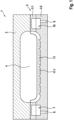
- the mold 1 comprises in the exemplary embodiment two mold halves 2, 3, which together delimit or define a shaping mold cavity 4 of the mold 1.
- the mold halves 2, 3 therefore each have one or more shaping walls, which each form a contour delimiting or defining the shaping mold cavity 4 of the mold 1.
- the concrete shape of the respective shaping walls on the mold half side and thus of the shaping mold cavity 4 of the mold 1 is typically selected with regard to the geometric-structural design of the particle foam molded part to be actually produced by means of the mold 1.
- At least one mold half 2, 3 can be mounted so as to be movable relative to the respective other mold half 2, 3.
- an open position of the mold 1 can be realized, in which, for example, for the purpose of removing a manufactured particle foam molded part, access to the mold cavity 4 is possible, and a Fig. 1
- the closed position of the molding tool 1 shown by way of example can be realized, in which no access to the mold cavity 4 is possible.
- at least one drive device (not shown), e.g. implemented as an (electric) motor, can be assigned to the molding tool 1.
- At least one mold half 2, 3 can comprise two mold half parts 2.1, 2.2, which are or can be connected to each other to form the respective mold half 2. At least one mold half 2 is thus formed in several parts. At least one mold half part 2.1 of the at least two mold half parts 2.1, 2.2 of the respective multi-part mold half 2 has the mentioned shaping wall of the respective mold half 2.
- the upper mold half 3 could alternatively or additionally be designed in a correspondingly multi-part manner.
- the figure shows that the two mold half parts 2.1, 2.2 can be or are connected to one another to form an intermediate space 5 through which a temperature control fluid serving to temperature control the mold half 2 can flow, such as a temperature control gas and/or a temperature control liquid.
- the multi-part mold half 2 is therefore formed with an integrated temperature control device due to the intermediate space 5 extending between the two mold half parts 2.1, 2.2 - at least when the mold half parts 2.1, 2.2 are connected as intended - and the possibility of flowing a temperature control fluid serving to temperature control the mold half 2 through this intermediate space 5, which can therefore also be referred to as a flow space.
- the intermediate space 5 typically extends almost completely in at least one spatial direction, i.e. e.g. B. a width and/or length direction, of the respective mold half 2, the tempering device has a large heat transfer surface and enables large-area tempering of particle foam material located in the mold cavity 4 during operation of the mold 1.
- a mold half 2 Due to the multi-part design of the mold half 2 with an intermediate space 5 extending between the two mold half parts 2.1, 2.2 and the possibility of flowing through this space with a tempering fluid serving to temper the mold half 2, a mold half 2 is thus realized which is structurally comparatively simple but highly efficient in terms of its temperability.
- the multi-part design of the mold half 2 also allows for functional and constructive degrees of freedom, as only one mold half part 2.1, 2.2 needs to be designed with a corresponding shaping wall, while the other mold half part 2.1, 2.2 can be designed with regard to other requirements, such as desired flow properties of a tempering fluid flowing through the intermediate space 5.
- the two mold halves 2.1, 2.2 can differ, at least in part, in their shape, as well as in other geometric-structural parameters, such as wall thickness. It is also conceivable that the two mold halves 2.1, 2.2 can be formed, at least in part, from the same or different materials or material structures, e.g. with regard to their thermal properties.
- a mold half 2.1, 2.2, which has the shaping wall can be formed from a material or material structure, such as a metal, in particular a light metal, with a comparatively higher heat transfer capacity in order to achieve the most efficient heat transfer to the particle foam material.
- the mold halves 2, 3 or mold half 2.1, 2.2 can be formed, for example, from metal, plastic, ceramic, or composite materials. It should also be added that the mold halves 2, 3 can be manufactured, for example, by machining or casting processes.
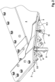
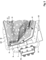
- a perspective view of the lower mold half part 2.2 shows that the or a multi-part mold half 2 is formed with one or more inflow sections 6 for a tempering fluid flowing into the intermediate space 5 and at least one pre-distribution space 7 communicating with the latter and delimited by wall sections of the mold half 2. It is evident that the pre-distribution space 7 can be formed jointly by the two mold half parts 2.1, 2.2 and thus delimited by wall sections of the two mold half parts 2.1, 2.2.
- the mold half part 2 can be structurally configured by means of a corresponding pre-distribution space 7 in such a way that a tempering fluid flowing into it does not flow completely directly into the intermediate space 5, but first into the pre-distribution space 7, in which it can be spatially distributed and only after corresponding distribution, in particular in terms of area, can flow into the intermediate space 5 in a manner distributed as evenly as possible.
- a respective inflow section 6 can in all cases have a connection option, e.g. flange-like or -shaped, for connecting a device with a temperature control fluid supply (not shown) connected line element 8, such as a hose, pipe, etc.
- a pre-distribution chamber 7 having a plurality of inflow sections 6 can optionally be assigned a plurality of temperature control fluid supplies, via which a temperature control fluid can flow into the pre-distribution chamber 7, e.g., via a fluid distribution device, e.g., designed as a fluid distribution block 14, dependently or independently of one another.
- a corresponding connection option can, for example, be provided with a thread onto which a corresponding counter-thread of a line element 8 can be screwed.
- the wall sections of a respective mold half part 2.1, 2.2 delimiting the pre-distribution space 7 - this includes in particular the wall sections of the mold half parts 2.1, 2.2 delimiting the pre-distribution space 7 from the intermediate space 5 - are arranged or designed in a crenellated or merlon-like manner.
- a desired inflow of the tempering fluid from the pre-distribution space 7 into the intermediate space 5 can be made possible, for example with regard to certain flow properties of the tempering fluid, such as a certain flow velocity distribution.
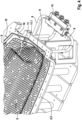
- Fig. 4 a perspective view of the lower mold half part 2.2 shows that the mold half 2 can be designed with one or more outflow sections 9 for a tempering fluid flowing out of the intermediate space 5 and at least one post-distribution space 10 communicating with these, arranged opposite the pre-distribution space 7 and delimited by wall sections of the mold half 2.
- the post-distribution space 10 can be formed jointly by the two mold half parts 2.1, 2.2 and thus delimited by wall sections of the two mold half parts 2.1, 2.2.
- the mold half part 2 can be structurally configured by means of a corresponding post-distribution space 10 in such a way that a tempering fluid flowing out of it does not flow completely directly out of the intermediate space 5, but first into the post-distribution space 10, in which it can be spatially distributed and only after corresponding distribution, in particular in terms of area, can flow out of the mold half 2 in a manner distributed as evenly as possible.
- a respective outflow section 9 can have a connection option, e.g., flange-like or -shaped, for connecting a line element 8 (not shown) connected to a temperature control fluid supply (not shown), such as a hose, pipe, etc.
- a post-distribution chamber 10 having multiple outflow sections 9 can optionally be assigned multiple temperature control fluid supplies, via which a temperature control fluid can flow out of the post-distribution chamber 10, e.g., via a fluid distribution device, e.g., designed as a fluid distribution block 13, dependently or independently of one another.
- a corresponding connection option can, for example, be provided with a thread onto which a corresponding counter-thread of a line element 8 can be screwed.
- the wall sections of a respective mold half part 2.1, 2.2 delimiting the secondary distribution space 10 - this includes in particular the wall sections of the mold half parts 2.1, 2.2 delimiting the secondary distribution space 10 from the intermediate space 5 - are arranged or formed at least in sections in a crenellated or embossed manner.
- a corresponding crenellated structure which, as Fig.
- a desired inflow of the tempering fluid from the intermediate space 5 into the post-distribution space 10 can be made possible, for example with regard to certain flow properties of the tempering fluid, such as a certain flow velocity distribution.
- the pre-distribution space 7 and/or the post-distribution space 10 can extend at least in at least one spatial direction of the mold 1, in particular in the width direction, at least over 50%, in particular at least over 55%, further in particular at least over 60%, further in particular at least over 65%, further in particular at least over 70%, further in particular at least over 75%, further in particular at least over 80%, further in particular at least over 85%, further in particular at least over 90%, further in particular at least over 95%, possibly even over 100% of the maximum dimensions of the respective mold half part(s) 2.1, 2.2.
- the influence of the pre-distribution space or the post-distribution space 10 on the flow properties of the tempering fluid flowing through the intermediate space 5 can thus be specifically selected via the respective spatial extent of the pre-distribution space 7 and/or the post-distribution space 10.
- One or more inflow sections 6 of the pre-distribution chamber 7 or the temperature control fluid supplies assigned thereto can communicate with one or more outflow sections 9 of the post-distribution chamber 10 or the temperature control fluid supplies assigned thereto, so that a temperature control fluid can be circulated between the inflow section(s) 6, the intermediate space 5 and the outflow section(s) 9.
- At least one heat exchanger device (not shown) can optionally be arranged in a corresponding circuit, via which a temperature control of the temperature control fluid to a specific target temperature or a desired target temperature range can be realized.
- the molding tool 1 has a flow influencing structure 11 comprising a plurality of flow influencing elements 11.1 arranged or formed at least partially, optionally completely, between the pre-distribution space 7 and the post-distribution space 10.
- the flow influencing structure 11 can thus extend between the pre-distribution space 7 and the post-distribution space 10, thus in the intermediate space 5.
- the flow influencing structure 11 or the flow influencing elements 11 forming it are formed in the intermediate space 5 in order to specifically influence the flow properties of the tempering fluid flowing through the intermediate space 5, in particular starting from the pre-distribution space 7 in the direction of the post-distribution space 10.
- the flow-influencing structure 11 can comprise a plurality of flow-influencing elements 11.1 of the same or different geometries in a uniform or irregular arrangement.
- the flow properties of the tempering fluid flowing through the intermediate space 5 can be influenced, in particular, by a deliberately selected uniform or irregular arrangement of flow-influencing elements 11.1 of the same or different geometries.
- the flow-influencing structure 11 can have one or more regions with uniformly arranged and/or aligned flow-influencing elements 11.1 of the same or different geometries and/or one or more regions with unevenly arranged and/or aligned flow-influencing elements 11.1 of the same or different geometries.
- the wall sections of at least one mold half part 2.1, 2.2 delimiting the intermediate space 5 can be covered with corresponding flow influencing elements 11.1 to an area of at least 50%, in particular at least 55%, further in particular at least 60%, further in particular at least 65%, further in particular at least 70%, further in particular at least 75%, further in particular at least 80%, further in particular at least 85%, further in particular at least 90%, further in particular at least 95%.
- Fig. 2 - 4 also indicate that a respective flow influencing element 11.1 has a contour of the corresponding mold half part 2.1 aligned, columnar or columnar basic shape.
- the cross-sectional geometry of a respective flow influencing element 11.1 can - this is fundamentally independent of its columnar or columnar basic shape - be selected with regard to a desired fluidic influence on the flow properties of the tempering fluid at the respective location at which the respective flow influencing element 11.1 is arranged in the intermediate space 5.
- the figures shown are examples of round or roundish or angular, oval, or ellipsoidal cross-sectional geometries.
- the figures show a lemon-like or lemon-shaped cross-sectional geometry.
- each flow-influencing element 11.1 can form a support surface for a mold half part 2.2 connected to the respective mold half part 2.1.
- Each flow-influencing element 11.1 can thus be arranged or configured to support the two parts against each other and to penetrate the intermediate space 5 between a first mold half part 2.1 and a second mold half part 2.2.
- each flow-influencing element 11.1 can additionally perform a supporting or carrying function, which has a positive effect on the structural properties, i.e., in particular, the stability, of the respective mold half 2.
- the figures further show that the mold half parts 2.1, 2.2 can be detachably connected or connected to one another (without causing damage or destruction).
- the connection between the mold half parts 2.1, 2.2 can thus be released as needed, which can significantly simplify service and/or repair work on the respective mold half 2.
- one or more sealing elements (not shown) can be provided, which enable sealing of the respective mold half, in particular in the joining plane of the respective mold half parts 2.1, 2.2.
- Fig. 3 , 4 Grooves or groove sections 12 are shown purely as examples to accommodate corresponding sealing elements.
- the detachable connection of the respective mold halves 2.1, 2.2 can be realized by positive and/or non-positive connection types.
- the mold halves 2.1, 2.2 can thus be detachably fastened to one another, for example, by a screw or rivet connection.
- Fig. 2 - 4 show by way of example - the mold half parts 2.1, 2.2 with corresponding mounting arrangements (not shown), such as holes 13, for receiving screw or rivet elements.
- a mold half part 2.1, 2.2 can have, for example, a shell-like or trough-like basic shape.
- the shell-like or trough-like basic shape promotes the formation of a corresponding intermediate space 5.
- other basic shapes are also conceivable in principle, such as plate-like or plate-shaped basic shapes.
- the basic shape of the mold halves 2, 3 and thus of the respective mold half parts 2.1, 2.2 is typically selected with regard to the particle foam molded part to be specifically produced using the mold 1.
- a mold half 2, 3 can be designed with at least one dipping edge section (not shown), which, in the closed position, dips at least partially into the mold cavity 4. This can optionally result in compression of the particle foam material filled into the mold cavity 4.
- the mold can be formed with a venting structure (not shown) comprising one or more venting elements.
- a venting structure comprising one or more venting elements.
- at least one mold half 2, 3 can be provided with venting elements formed, for example, by openings, gaps, depressions, etc., which enable venting of the mold cavity 4, for example, during filling of the mold cavity 4 with particle foam material.
- Corresponding venting elements can also be formed by or comprise dipping edge gaps.
- the mold 1 can be sealed in the closed position so that an undesired escape of a fluid flowing into or in the mold cavity 4, such as a liquid, from the mold cavity 4 is not possible.
- a method for producing a particle foam molded part can be implemented using the molding tool 1 shown in the figures.
- the method typically comprises a step of filling the mold cavity 4 with a particle foam material, a step of tempering the particle foam material to form a particle foam molded part, and a step of removing the particle foam molded part from the mold cavity 4.
- the tempering is carried out in particular by flowing at least one tempering fluid used to temper the at least one mold half 2, 3 through the intermediate space 5 of at least one multi-part mold half.
Landscapes
- Engineering & Computer Science (AREA)
- Mechanical Engineering (AREA)
- Moulds For Moulding Plastics Or The Like (AREA)
Claims (10)
- Moule de moulage (1) pour le traitement d'un matériau expansible ou expansé en mousse particulaire pour la fabrication d'une pièce moulée en mousse particulaire, comprenant au moins deux moitiés d'outil de moulage (2, 3) définissant une cavité d'outil de moulage (4) de l'outil de moulage (1), au moins une moitié de moule (2, 3) comprenant au moins deux parties de moule (2.1, 2.2) pouvant être reliées ou reliées entre elles en formant un espace intermédiaire (5) pouvant être traversé par un fluide de régulation de température servant à la régulation de température de ladite au moins une moitié de moule (2, 3),caractérisé en ce qu'au moins une moitié d'outil de formage (2.1, 2.2) est conçue avec au moins une section d'admission (6) pour un fluide de régulation de température entrant dans l'espace intermédiaire (5) et au moins un espace de distribution préalable (7) communiquant avec celle-ci et délimité par des sections de paroi de la moitié d'outil de formage (2.1, 2.2),à l'intérieur de l'espace de pré-distribution (7) se trouvent plusieurs sections d'entrée d'écoulement réparties ou disposées dans l'espace, les sections de paroi délimitant l'espace de distribution préalable (7) étant disposées ou conçues au moins par sections en forme de créneaux, une structure en créneaux appropriée permettant l'écoulement souhaité du fluide de régulation de température de l'espace de distribution préalable (7) vers l'espace intermédiaire (5) en tenant compte des propriétés d'écoulement du fluide de régulation de température ; etla au moins une moitié de moule (2.1, 2.2) est conçue avec au moins une section d'écoulement (9) pour un fluide de régulation de température s'écoulant de l'espace intermédiaire (5) et au moins un espace de redistribution (10) communiquant avec celui-ci, disposé en face de l'espace de pré-distribution et par des sections de paroi de la moitié de l'outil de formage (2.1, 2.2), plusieurs sections d'écoulement (9) réparties ou disposées dans l'espace étant présentes à l'intérieur de l'espace de redistribution (10), les sections de paroi délimitant l'espace de redistribution (10) étant disposées ou conçues au moins par sections en forme de créneaux, une structure de créneaux appropriée permettant l'écoulement souhaité du fluide de régulation de température de l'espace intermédiaire (5) vers l'espace de redistribution (10) en tenant compte des propriétés d'écoulement spécifiques du fluide de régulation de température ;comprenant en outre une structure d'influence de l'écoulement (11) comprenant plusieurs éléments d'influence de l'écoulement (11.1) disposés au moins par sections entre la section d'entrée (6) et la section de sortie (9), la géométrie de la section transversale d'un élément respectif (11.1) d'influence de l'écoulement étant choisie en vue d'une influence souhaitée, sur le plan de la technique des fluides, des propriétés d'écoulement du fluide de régulation de température à l'endroit respectif où l'élément respectif (11.1) d'influence de l'écoulement est disposé dans l'espace intermédiaire (5).
- Moule de moulage selon la revendication 1, caractérisé en ce que la chambre de distribution (7) s'étend au moins dans la zone de la section d'entrée d'écoulement dans au moins une direction spatiale, en particulier dans le sens de la largeur, sur au moins 50 % des dimensions maximales de la moitié du moule (2, 3) ou d'au moins une partie de la moitié du moule (2.1, 2.2).
- Moule de moulage selon l'une des revendications précédentes, caractérisé en ce que l'espace de distribution secondaire (10) s'étend, au moins dans la zone de la section d'écoulement (9), dans au moins une direction spatiale, en particulier dans le sens de la largeur, au moins 50 % des dimensions maximales de la moitié de l'outil de formage (2, 3) ou d'au moins une partie de la moitié de l'outil de formage (2.1, 2.2).
- Moule de moulage selon l'une des revendications précédentes, caractérisé en ce que la structure d'influence de l'écoulement (11) s'étend au moins par sections entre la chambre de pré-distribution (7) et la chambre de post-distribution (10).
- Moule de formage selon l'une des revendications précédentes, caractérisé en ce qu'un élément respectif (11.1) d'influence sur l'écoulement présente une forme de base en colonne, orientée en particulier en direction d'un contour de la partie respective (2.1, 2.2) de l'outil de formage délimitant la cavité (4) de l'outil de formage.
- Moule de formage selon la revendication 5, caractérisé en ce qu'un élément respectif d'influence de l'écoulement (11.1) présente, vu en coupe transversale, une forme ronde ou ovale, en particulier ellipsoïdale.
- Moule de formage selon l'une des revendications 4 à 6, caractérisé en ce qu'une extrémité libre d'au moins un élément de contrôle de l'écoulement (11.1) forme une surface d'appui pour une moitié d'outil de formage (2.2) pouvant être reliée ou reliée à la moitié d'outil de formage respective (2.1, 2.2).
- Moule de formage selon l'une des revendications précédentes, caractérisé en ce que les moitiés d'outil de formage (2.1, 2.2) formant au moins une moitié d'outil de formage (2, 3) sont fixées l'une à l'autre de manière amovible, en particulier par un assemblage vissé.
- Moule de formage selon l'une des revendications précédentes, caractérisé en ce qu'il est conçu comme un outil à arêtes plongeantes.
- Moule de formage selon l'une des revendications précédentes, caractérisé en ce qu'au moins une moitié d'outil de formage (2, 3) comprend une structure de ventilation pour ventiler la cavité de l'outil de formage (4) qui donne la forme.
Applications Claiming Priority (1)
| Application Number | Priority Date | Filing Date | Title |
|---|---|---|---|
| DE102021132978.7A DE102021132978A1 (de) | 2021-12-14 | 2021-12-14 | Formwerkzeug zur Herstellung eines Partikelschaumformteils |
Publications (3)
| Publication Number | Publication Date |
|---|---|
| EP4197736A1 EP4197736A1 (fr) | 2023-06-21 |
| EP4197736C0 EP4197736C0 (fr) | 2025-04-02 |
| EP4197736B1 true EP4197736B1 (fr) | 2025-04-02 |
Family
ID=84520167
Family Applications (1)
| Application Number | Title | Priority Date | Filing Date |
|---|---|---|---|
| EP22213035.3A Active EP4197736B1 (fr) | 2021-12-14 | 2022-12-13 | Moule pour la fabrication d'une pièce moulée en mousse particulaire |
Country Status (2)
| Country | Link |
|---|---|
| EP (1) | EP4197736B1 (fr) |
| DE (1) | DE102021132978A1 (fr) |
Families Citing this family (1)
| Publication number | Priority date | Publication date | Assignee | Title |
|---|---|---|---|---|
| DE102024204951A1 (de) * | 2024-05-28 | 2025-12-04 | Volkswagen Aktiengesellschaft | Vorrichtung und Verfahren zur Herstellung eines Schaumbauteils |
Family Cites Families (9)
| Publication number | Priority date | Publication date | Assignee | Title |
|---|---|---|---|---|
| US3837769A (en) * | 1972-07-29 | 1974-09-24 | H Erlenbach | Apparatus for the manufacture of molded articles of foam-forming thermoplastic synthetics |
| US4192638A (en) | 1976-05-17 | 1980-03-11 | Gerard Lezier | Molding device having heat transfer chambers insulated from each other for molding expandable thermoplastic resin particles |
| US4627946A (en) * | 1983-11-07 | 1986-12-09 | Morval-Durofoam Ltd. | Method and molding apparatus for molding expanded polystyrene articles having smooth surfaces |
| EP0909626A3 (fr) * | 1997-10-17 | 2000-02-02 | TOHOKU MUNEKATA Co., Ltd. | Procédé et dispositif pour mouler par injection des matières plastiques |
| US6116888A (en) * | 1998-07-29 | 2000-09-12 | Owens-Brockway Plastic Products Inc. | Prototype mold for blow-molding hollow plastic containers and method of making same |
| JP2004536724A (ja) * | 2001-07-31 | 2004-12-09 | エスケイ ケミカルズ カンパニー リミテッド | 製品を鋳造するための方法及びそれに用いる鋳型 |
| JP5047643B2 (ja) | 2007-01-30 | 2012-10-10 | 株式会社カネカ | 熱可塑性樹脂発泡体の製造方法 |
| DE102012024051B4 (de) | 2012-12-08 | 2021-01-28 | Volkswagen Aktiengesellschaft | Temperierbares Werkzeug zur Formgebung von Werkstücken |
| DE102014112526A1 (de) | 2014-09-01 | 2016-03-03 | Illinois Tool Works Inc. | Formwerkzeug und Gussform |
-
2021
- 2021-12-14 DE DE102021132978.7A patent/DE102021132978A1/de active Pending
-
2022
- 2022-12-13 EP EP22213035.3A patent/EP4197736B1/fr active Active
Also Published As
| Publication number | Publication date |
|---|---|
| EP4197736C0 (fr) | 2025-04-02 |
| DE102021132978A1 (de) | 2023-06-15 |
| EP4197736A1 (fr) | 2023-06-21 |
Similar Documents
| Publication | Publication Date | Title |
|---|---|---|
| EP2511030B1 (fr) | Procédé de fabrication d'un composant doté d'au moins un élément de construction agencé dans le composant et composant doté d'au moins un élément de construction | |
| DE102018208070A1 (de) | Verfahren zum Herstellen einer Batteriemodulvorrichtung für ein Kraftfahrzeug, Batteriemodulvorrichtung für ein Kraftfahrzeug und Kraftfahrzeug mit einer Batteriemodulvorrichtung | |
| EP1980380A1 (fr) | Dispositif de chauffage ou de refroidissement, en particulier comme partie d'un moule destiné au traitement de matières plastiques, tel qu' un moule d'injection pour plastique. | |
| DE102012016309A1 (de) | Verfahren zur Herstellung einer Kernschicht eines Leichtbauelementes sowie Leichtbauelement | |
| DE112012007279T5 (de) | Fahrzeuginnenplatte und Verfahren zum Herstellen derselben | |
| DE102013203372A1 (de) | Formkernpaket zum formen eines powder-slush-formwerkzeugs | |
| DE102017101835A1 (de) | Verfahren zur Pulverbett-basierten additiven Fertigung von mindestens einem Bauteil und Pulverbett-additiv gefertigte(s) Bauteil(e) sowie Anlage und Bauplattform zur Durchführung des Verfahrens | |
| EP3292988B1 (fr) | Support porteur de plateforme interchangeable avec un contrôle de temperature amélioré | |
| DE112012007278T5 (de) | Fahrzeuginnenplatte und Verfahren zum Herstellen derselben | |
| EP4197736B1 (fr) | Moule pour la fabrication d'une pièce moulée en mousse particulaire | |
| EP3527353B1 (fr) | Boitier pour télécommande monolithique | |
| EP2136982B1 (fr) | Moule et procédé pour la fabrication de peaux et de corps moulés en plastique | |
| EP4153395B1 (fr) | Moule pour le traitement de particules plastiques expansibles ou expansées | |
| DE102014221423A1 (de) | Verfahren zur Herstellung großer Warmumformwerkzeuge mittels eines generativen Fertigungsverfahrens | |
| EP3661718B1 (fr) | Moule | |
| WO2002072334A2 (fr) | Procede pour produire des pieces moulees en matiere plastique au moyen d'un moule de soufflage et d'une lance d'injection | |
| DE20111198U1 (de) | Kaliberplatte mit einem Einsatzteil für eine Formgebungseinrichtung | |
| DE102010018114B4 (de) | Verfahren zur Herstellung von Bauteilen mittels Polymer- oder Kunststoffguss oder aus Faserverbund-Kunststoffen | |
| DE102019127666A1 (de) | Lochplatte zum Granulieren von Schmelzen sowie Verfahren zu deren Herstellung | |
| DE102014224720A1 (de) | Verfahren zur Herstellung eines schnittbearbeiteten Formteils mit einer Kunststoffmatrix und Verstärkungsfasern | |
| DE102014112526A1 (de) | Formwerkzeug und Gussform | |
| EP3088153B1 (fr) | Outil de formage | |
| DE19744165C2 (de) | Werkzeug zum Herstellen eines Partikelschaumstoff-Formkörpers und Verfahren zur Herstellung eines solchen Werkzeuges | |
| DE102017216654A1 (de) | Ausrichten und Fixieren eines Werkstücks für ein Weiterbearbeiten mittels eines additiven Herstellungsverfahrens | |
| DE102006001716A1 (de) | Verfahren und Anordnung zur Herstellung von konturbezogenen Temperierkanälen in Werkzeugen bzw. Werkzeugeinsätzen, Kernen und Schiebern |
Legal Events
| Date | Code | Title | Description |
|---|---|---|---|
| PUAI | Public reference made under article 153(3) epc to a published international application that has entered the european phase |
Free format text: ORIGINAL CODE: 0009012 |
|
| STAA | Information on the status of an ep patent application or granted ep patent |
Free format text: STATUS: THE APPLICATION HAS BEEN PUBLISHED |
|
| AK | Designated contracting states |
Kind code of ref document: A1 Designated state(s): AL AT BE BG CH CY CZ DE DK EE ES FI FR GB GR HR HU IE IS IT LI LT LU LV MC ME MK MT NL NO PL PT RO RS SE SI SK SM TR |
|
| RAP3 | Party data changed (applicant data changed or rights of an application transferred) |
Owner name: PARAT TECHNOLOGY GROUP GMBH |
|
| STAA | Information on the status of an ep patent application or granted ep patent |
Free format text: STATUS: REQUEST FOR EXAMINATION WAS MADE |
|
| 17P | Request for examination filed |
Effective date: 20231220 |
|
| RBV | Designated contracting states (corrected) |
Designated state(s): AL AT BE BG CH CY CZ DE DK EE ES FI FR GB GR HR HU IE IS IT LI LT LU LV MC ME MK MT NL NO PL PT RO RS SE SI SK SM TR |
|
| STAA | Information on the status of an ep patent application or granted ep patent |
Free format text: STATUS: EXAMINATION IS IN PROGRESS |
|
| 17Q | First examination report despatched |
Effective date: 20240320 |
|
| GRAP | Despatch of communication of intention to grant a patent |
Free format text: ORIGINAL CODE: EPIDOSNIGR1 |
|
| STAA | Information on the status of an ep patent application or granted ep patent |
Free format text: STATUS: GRANT OF PATENT IS INTENDED |
|
| INTG | Intention to grant announced |
Effective date: 20241206 |
|
| GRAS | Grant fee paid |
Free format text: ORIGINAL CODE: EPIDOSNIGR3 |
|
| GRAA | (expected) grant |
Free format text: ORIGINAL CODE: 0009210 |
|
| STAA | Information on the status of an ep patent application or granted ep patent |
Free format text: STATUS: THE PATENT HAS BEEN GRANTED |
|
| AK | Designated contracting states |
Kind code of ref document: B1 Designated state(s): AL AT BE BG CH CY CZ DE DK EE ES FI FR GB GR HR HU IE IS IT LI LT LU LV MC ME MK MT NL NO PL PT RO RS SE SI SK SM TR |
|
| REG | Reference to a national code |
Ref country code: GB Ref legal event code: FG4D Free format text: NOT ENGLISH |
|
| REG | Reference to a national code |
Ref country code: CH Ref legal event code: EP |
|
| REG | Reference to a national code |
Ref country code: IE Ref legal event code: FG4D Free format text: LANGUAGE OF EP DOCUMENT: GERMAN |
|
| U01 | Request for unitary effect filed |
Effective date: 20250402 |
|
| U07 | Unitary effect registered |
Designated state(s): AT BE BG DE DK EE FI FR IT LT LU LV MT NL PT RO SE SI Effective date: 20250408 |
|
| PG25 | Lapsed in a contracting state [announced via postgrant information from national office to epo] |
Ref country code: ES Free format text: LAPSE BECAUSE OF FAILURE TO SUBMIT A TRANSLATION OF THE DESCRIPTION OR TO PAY THE FEE WITHIN THE PRESCRIBED TIME-LIMIT Effective date: 20250402 |
|
| PG25 | Lapsed in a contracting state [announced via postgrant information from national office to epo] |
Ref country code: GR Free format text: LAPSE BECAUSE OF FAILURE TO SUBMIT A TRANSLATION OF THE DESCRIPTION OR TO PAY THE FEE WITHIN THE PRESCRIBED TIME-LIMIT Effective date: 20250703 Ref country code: NO Free format text: LAPSE BECAUSE OF FAILURE TO SUBMIT A TRANSLATION OF THE DESCRIPTION OR TO PAY THE FEE WITHIN THE PRESCRIBED TIME-LIMIT Effective date: 20250702 |
|
| PG25 | Lapsed in a contracting state [announced via postgrant information from national office to epo] |
Ref country code: PL Free format text: LAPSE BECAUSE OF FAILURE TO SUBMIT A TRANSLATION OF THE DESCRIPTION OR TO PAY THE FEE WITHIN THE PRESCRIBED TIME-LIMIT Effective date: 20250402 |
|
| PG25 | Lapsed in a contracting state [announced via postgrant information from national office to epo] |
Ref country code: HR Free format text: LAPSE BECAUSE OF FAILURE TO SUBMIT A TRANSLATION OF THE DESCRIPTION OR TO PAY THE FEE WITHIN THE PRESCRIBED TIME-LIMIT Effective date: 20250402 |
|
| PG25 | Lapsed in a contracting state [announced via postgrant information from national office to epo] |
Ref country code: RS Free format text: LAPSE BECAUSE OF FAILURE TO SUBMIT A TRANSLATION OF THE DESCRIPTION OR TO PAY THE FEE WITHIN THE PRESCRIBED TIME-LIMIT Effective date: 20250702 |
|
| PG25 | Lapsed in a contracting state [announced via postgrant information from national office to epo] |
Ref country code: IS Free format text: LAPSE BECAUSE OF FAILURE TO SUBMIT A TRANSLATION OF THE DESCRIPTION OR TO PAY THE FEE WITHIN THE PRESCRIBED TIME-LIMIT Effective date: 20250802 |
|
| PG25 | Lapsed in a contracting state [announced via postgrant information from national office to epo] |
Ref country code: SM Free format text: LAPSE BECAUSE OF FAILURE TO SUBMIT A TRANSLATION OF THE DESCRIPTION OR TO PAY THE FEE WITHIN THE PRESCRIBED TIME-LIMIT Effective date: 20250402 |
|
| U20 | Renewal fee for the european patent with unitary effect paid |
Year of fee payment: 4 Effective date: 20251210 |
|
| PG25 | Lapsed in a contracting state [announced via postgrant information from national office to epo] |
Ref country code: CZ Free format text: LAPSE BECAUSE OF FAILURE TO SUBMIT A TRANSLATION OF THE DESCRIPTION OR TO PAY THE FEE WITHIN THE PRESCRIBED TIME-LIMIT Effective date: 20250402 |
|
| PG25 | Lapsed in a contracting state [announced via postgrant information from national office to epo] |
Ref country code: SK Free format text: LAPSE BECAUSE OF FAILURE TO SUBMIT A TRANSLATION OF THE DESCRIPTION OR TO PAY THE FEE WITHIN THE PRESCRIBED TIME-LIMIT Effective date: 20250402 |
|
| PLBE | No opposition filed within time limit |
Free format text: ORIGINAL CODE: 0009261 |
|
| STAA | Information on the status of an ep patent application or granted ep patent |
Free format text: STATUS: NO OPPOSITION FILED WITHIN TIME LIMIT |
|
| REG | Reference to a national code |
Ref country code: CH Ref legal event code: L10 Free format text: ST27 STATUS EVENT CODE: U-0-0-L10-L00 (AS PROVIDED BY THE NATIONAL OFFICE) Effective date: 20260211 |
|
| 26N | No opposition filed |
Effective date: 20260105 |