EP4197740B1 - Vorrichtung und verfahren zum erwärmen von kunststoffvorformlingen mit anpassung der heizleistung - Google Patents
Vorrichtung und verfahren zum erwärmen von kunststoffvorformlingen mit anpassung der heizleistung Download PDFInfo
- Publication number
- EP4197740B1 EP4197740B1 EP22212218.6A EP22212218A EP4197740B1 EP 4197740 B1 EP4197740 B1 EP 4197740B1 EP 22212218 A EP22212218 A EP 22212218A EP 4197740 B1 EP4197740 B1 EP 4197740B1
- Authority
- EP
- European Patent Office
- Prior art keywords
- heating
- plastic preforms
- transport
- devices
- heating devices
- Prior art date
- Legal status (The legal status is an assumption and is not a legal conclusion. Google has not performed a legal analysis and makes no representation as to the accuracy of the status listed.)
- Active
Links
Images


Classifications
-
- B—PERFORMING OPERATIONS; TRANSPORTING
- B29—WORKING OF PLASTICS; WORKING OF SUBSTANCES IN A PLASTIC STATE IN GENERAL
- B29C—SHAPING OR JOINING OF PLASTICS; SHAPING OF MATERIAL IN A PLASTIC STATE, NOT OTHERWISE PROVIDED FOR; AFTER-TREATMENT OF THE SHAPED PRODUCTS, e.g. REPAIRING
- B29C49/00—Blow-moulding, i.e. blowing a preform or parison to a desired shape within a mould; Apparatus therefor
- B29C49/42—Component parts, details or accessories; Auxiliary operations
- B29C49/64—Heating or cooling preforms, parisons or blown articles
- B29C49/6409—Thermal conditioning of preforms
-
- B—PERFORMING OPERATIONS; TRANSPORTING
- B29—WORKING OF PLASTICS; WORKING OF SUBSTANCES IN A PLASTIC STATE IN GENERAL
- B29C—SHAPING OR JOINING OF PLASTICS; SHAPING OF MATERIAL IN A PLASTIC STATE, NOT OTHERWISE PROVIDED FOR; AFTER-TREATMENT OF THE SHAPED PRODUCTS, e.g. REPAIRING
- B29C49/00—Blow-moulding, i.e. blowing a preform or parison to a desired shape within a mould; Apparatus therefor
- B29C49/42—Component parts, details or accessories; Auxiliary operations
- B29C49/4205—Handling means, e.g. transfer, loading or discharging means
- B29C49/42065—Means specially adapted for transporting preforms
-
- B—PERFORMING OPERATIONS; TRANSPORTING
- B29—WORKING OF PLASTICS; WORKING OF SUBSTANCES IN A PLASTIC STATE IN GENERAL
- B29C—SHAPING OR JOINING OF PLASTICS; SHAPING OF MATERIAL IN A PLASTIC STATE, NOT OTHERWISE PROVIDED FOR; AFTER-TREATMENT OF THE SHAPED PRODUCTS, e.g. REPAIRING
- B29C49/00—Blow-moulding, i.e. blowing a preform or parison to a desired shape within a mould; Apparatus therefor
- B29C49/42—Component parts, details or accessories; Auxiliary operations
- B29C49/64—Heating or cooling preforms, parisons or blown articles
- B29C49/6409—Thermal conditioning of preforms
- B29C49/6418—Heating of preforms
-
- B—PERFORMING OPERATIONS; TRANSPORTING
- B29—WORKING OF PLASTICS; WORKING OF SUBSTANCES IN A PLASTIC STATE IN GENERAL
- B29C—SHAPING OR JOINING OF PLASTICS; SHAPING OF MATERIAL IN A PLASTIC STATE, NOT OTHERWISE PROVIDED FOR; AFTER-TREATMENT OF THE SHAPED PRODUCTS, e.g. REPAIRING
- B29C49/00—Blow-moulding, i.e. blowing a preform or parison to a desired shape within a mould; Apparatus therefor
- B29C49/42—Component parts, details or accessories; Auxiliary operations
- B29C49/78—Measuring, controlling or regulating
- B29C49/786—Temperature
- B29C2049/7861—Temperature of the preform
-
- B—PERFORMING OPERATIONS; TRANSPORTING
- B29—WORKING OF PLASTICS; WORKING OF SUBSTANCES IN A PLASTIC STATE IN GENERAL
- B29C—SHAPING OR JOINING OF PLASTICS; SHAPING OF MATERIAL IN A PLASTIC STATE, NOT OTHERWISE PROVIDED FOR; AFTER-TREATMENT OF THE SHAPED PRODUCTS, e.g. REPAIRING
- B29C49/00—Blow-moulding, i.e. blowing a preform or parison to a desired shape within a mould; Apparatus therefor
- B29C49/42—Component parts, details or accessories; Auxiliary operations
- B29C49/78—Measuring, controlling or regulating
- B29C2049/7878—Preform or article handling, e.g. flow from station to station
-
- B—PERFORMING OPERATIONS; TRANSPORTING
- B29—WORKING OF PLASTICS; WORKING OF SUBSTANCES IN A PLASTIC STATE IN GENERAL
- B29C—SHAPING OR JOINING OF PLASTICS; SHAPING OF MATERIAL IN A PLASTIC STATE, NOT OTHERWISE PROVIDED FOR; AFTER-TREATMENT OF THE SHAPED PRODUCTS, e.g. REPAIRING
- B29C49/00—Blow-moulding, i.e. blowing a preform or parison to a desired shape within a mould; Apparatus therefor
- B29C49/42—Component parts, details or accessories; Auxiliary operations
- B29C49/64—Heating or cooling preforms, parisons or blown articles
- B29C49/68—Ovens specially adapted for heating preforms or parisons
-
- B—PERFORMING OPERATIONS; TRANSPORTING
- B29—WORKING OF PLASTICS; WORKING OF SUBSTANCES IN A PLASTIC STATE IN GENERAL
- B29C—SHAPING OR JOINING OF PLASTICS; SHAPING OF MATERIAL IN A PLASTIC STATE, NOT OTHERWISE PROVIDED FOR; AFTER-TREATMENT OF THE SHAPED PRODUCTS, e.g. REPAIRING
- B29C49/00—Blow-moulding, i.e. blowing a preform or parison to a desired shape within a mould; Apparatus therefor
- B29C49/42—Component parts, details or accessories; Auxiliary operations
- B29C49/64—Heating or cooling preforms, parisons or blown articles
- B29C49/68—Ovens specially adapted for heating preforms or parisons
- B29C49/683—Adjustable or modular conditioning means, e.g. position and number of heating elements
-
- B—PERFORMING OPERATIONS; TRANSPORTING
- B29—WORKING OF PLASTICS; WORKING OF SUBSTANCES IN A PLASTIC STATE IN GENERAL
- B29C—SHAPING OR JOINING OF PLASTICS; SHAPING OF MATERIAL IN A PLASTIC STATE, NOT OTHERWISE PROVIDED FOR; AFTER-TREATMENT OF THE SHAPED PRODUCTS, e.g. REPAIRING
- B29C49/00—Blow-moulding, i.e. blowing a preform or parison to a desired shape within a mould; Apparatus therefor
- B29C49/42—Component parts, details or accessories; Auxiliary operations
- B29C49/64—Heating or cooling preforms, parisons or blown articles
- B29C49/68—Ovens specially adapted for heating preforms or parisons
- B29C49/6845—Ovens specially adapted for heating preforms or parisons using ventilation, e.g. a fan
-
- B—PERFORMING OPERATIONS; TRANSPORTING
- B29—WORKING OF PLASTICS; WORKING OF SUBSTANCES IN A PLASTIC STATE IN GENERAL
- B29C—SHAPING OR JOINING OF PLASTICS; SHAPING OF MATERIAL IN A PLASTIC STATE, NOT OTHERWISE PROVIDED FOR; AFTER-TREATMENT OF THE SHAPED PRODUCTS, e.g. REPAIRING
- B29C49/00—Blow-moulding, i.e. blowing a preform or parison to a desired shape within a mould; Apparatus therefor
- B29C49/42—Component parts, details or accessories; Auxiliary operations
- B29C49/78—Measuring, controlling or regulating
- B29C49/786—Temperature
-
- B—PERFORMING OPERATIONS; TRANSPORTING
- B29—WORKING OF PLASTICS; WORKING OF SUBSTANCES IN A PLASTIC STATE IN GENERAL
- B29K—INDEXING SCHEME ASSOCIATED WITH SUBCLASSES B29B, B29C OR B29D, RELATING TO MOULDING MATERIALS OR TO MATERIALS FOR MOULDS, REINFORCEMENTS, FILLERS OR PREFORMED PARTS, e.g. INSERTS
- B29K2067/00—Use of polyesters or derivatives thereof, as moulding material
- B29K2067/003—PET, i.e. poylethylene terephthalate
-
- B—PERFORMING OPERATIONS; TRANSPORTING
- B29—WORKING OF PLASTICS; WORKING OF SUBSTANCES IN A PLASTIC STATE IN GENERAL
- B29L—INDEXING SCHEME ASSOCIATED WITH SUBCLASS B29C, RELATING TO PARTICULAR ARTICLES
- B29L2031/00—Other particular articles
- B29L2031/712—Containers; Packaging elements or accessories, Packages
-
- B—PERFORMING OPERATIONS; TRANSPORTING
- B29—WORKING OF PLASTICS; WORKING OF SUBSTANCES IN A PLASTIC STATE IN GENERAL
- B29L—INDEXING SCHEME ASSOCIATED WITH SUBCLASS B29C, RELATING TO PARTICULAR ARTICLES
- B29L2031/00—Other particular articles
- B29L2031/712—Containers; Packaging elements or accessories, Packages
- B29L2031/7158—Bottles
Definitions
- the present invention relates to a device and a method for heating plastic preforms.
- Such devices and methods have long been known from the prior art and are described, for example, in the patent documents EP3446852A1 , US2014/145375A1 , EP2436507A2 and US2020/307064A1 described.
- the plastic preforms are heated to a predetermined temperature within a heating device such as an oven, using a large number of heating devices. This is usually the temperature required for blow molding or forming the plastic preforms into plastic containers.
- a heating device such as an oven
- Known blow molding machines have an electric stretching unit which, as is known from the applicant's internal state of the art, enables different blow wheel speeds for the same container qualities and thus variable production numbers.
- a speed-adjustable blow molding machine is also known from the DE 10 2017 126 240 A1 known. Even well-known filling machines and labeling machines can vary the speed.
- the present invention is therefore based on the object of providing a device and a method which enables the transport speed of the furnace to be regulated while maintaining constant preform temperatures at the exit of the furnace. This object is achieved according to the invention by the subject matter of the independent claims. Advantageous embodiments and further developments are the subject matter of the subclaims.
- the invention is therefore directed to a method for heating plastic preforms, wherein the plastic preforms are transported within a heating device along a predetermined transport path and are heated to a predetermined temperature during this transport by means of a plurality of heating devices arranged along the transport path, and wherein a heating power of the heating devices impinging on the plastic preforms is variable.
- the heating power of the heating devices impinging on the plastic preforms is regulated as a function of a transport speed of the plastic preforms.
- the heating power of each heating device preferably individually to the transport speed of the plastic preforms.
- the heating power of the heating devices is reduced at slower transport speeds, since the plastic preforms remain in the heating device for a longer time and thus also in front of the individual heating devices for a longer time. Accordingly, the heating power of the heating device is increased at a higher transport speed, since the time period in which the plastic preforms remain in the heating device is shorter.
- This regulation of the heating power is particularly advantageous with regard to a variable blow molding machine, which is arranged after the heating device in the transport direction of the plastic preforms.
- the proposed method also provides regulation of the heating devices without much control effort. In particular, this can also be done in a blocked overall system with several blocked machines, such as For example, heating equipment, blow molding machines, filling equipment, sealers, sterilization equipment, or the like, variable output can be achieved in a simple manner.
- the radiated power is constant during a heating zone (which is a gross simplification, but does not have any significant impact on the final result) and thus the energy absorbed by the preforms increases linearly in front of each heating device that is switched on and remains constant in front of a heating device that is switched off.
- the transport device is preferably a rotating transport device with straight and curved transport sections.
- the transport device preferably has a linear section along which the plastic preforms are moved along a linear transport path.
- the transport device advantageously also has at least one, preferably two, curved sections, with the linear sections and the curved sections preferably alternating.
- At least one curved section is a compensation zone in which no heating devices are arranged.
- the temperature of the plastic preform therefore remains constant in the compensation zone or does not change significantly.
- a transport wheel for transferring the heated plastic preforms to the subsequent blow molding machine can also be such a compensation zone, so that the temperature of the plastic preform remains constant or at least almost constant from the last heating device to the feed into the blow molding machine (according to a simplified assumption).
- the gradient of the energy increase remains constant when the heating device is switched on, but the time that the preform remains in front of the heating device and is heated by it changes.
- the heating power must be reduced at slower speeds and increased accordingly at faster speeds in order to ensure the same energy input.
- a control variable of the individual heating devices is changed and in particular reduced and/or increased.
- the compensation zones at the deflection and at the transport star cannot be fully compensated. Therefore, slightly different curves often arise here.
- the energy can be slightly increased in front of these zones and, preferably, the heating output of the heating devices arranged in front of these compensation zones can be higher.
- the similar curves of the heating histories can take place according to various mathematical patterns and can, for example, be the sum of the least squares of the errors, or the attempt to ensure that the areas between the two different curves are minimal or that the energy curve is identical at the end of each heating zone.
- This adjustment can preferably be made in the main control, in another edge device or in a cloud-based optimizer.
- heating device 3 can only be operated at 30% and heating device 4, preferably at the same height, at 81%.
- a variable blow molding machine is preferably also made possible.
- the transport speed in the heating device can therefore be increased if the output rate of the blow molding machine is to be increased.
- the speed of the blow molding machine can also be adapted to the speed of the heating device or the blowing process in the blow molding machine can be changed accordingly.
- the heating power of each heating device and/or in particular of neighboring heating devices is regulated and/or changed individually and/or independently of one another.
- the heating power of each heating device can therefore be regulated individually, independently of the heating power of the other heating devices, so that the heating power can be adapted to the respective transport speed in such a way that the temperature profile to be applied to the plastic preforms is always the same, regardless of the transport speed.
- Each heating device preferably forms a separate and independent heating zone.
- the heating power of the heating devices and/or the transport speed of the plastic preforms are continuously controlled.
- the heating power of the heating device can be set to any value between a heating power of 0% and 100%.
- a specific range can also be specified within which any value can be set, such as a range of 10% - 85%.
- At least one heating device and preferably several heating devices are arranged so as to be displaceable along the transport path of the heating device.
- the at least one heating device is displaced along the linear transport section or is arranged so as to be displaceable along the linear transport section.
- at least the heating device which heats the plastic preforms last or which is arranged directly before the Compensation zone of the transport star or, viewed in the transport direction of the plastic preforms, at the end of the transport device.
- one or more heating devices arranged at other points on the transport device are arranged so that they can be moved, such as the first heating device and/or the heating devices arranged before and/or after the compensation zone of the curved transport section.
- the distance to neighboring heating devices can be adjusted and the section on the transport device at which a specific and/or final temperature profile is applied to the plastic preform can be individually determined.
- an internal and/or external temperature of the plastic preforms is recorded within the heating device and this temperature is used to regulate the heating power of the heating devices.
- at least one temperature sensor and particularly preferably several temperature sensors are arranged within the heating device.
- the temperature sensors preferably determine the external and/or internal temperature of the preforms at one or more locations in order to draw conclusions about the heating history.
- a higher-level control system can also adjust the heating parameters based on this data.
- the temperature sensors can preferably, but not exclusively, be pyrometers or IR cameras. These can be advantageously swiveled to vary the measuring point. Alternatively, the measuring point can also be varied using mirrors.
- the adjustment of the heating power is carried out based on a different control concept, which is based on a temperature of the preforms and/or wall thickness information of the containers (or other container characteristics such as top load etc%) on a neural network or machine learning model.
- the heating power is regulated via at least one first corner recipe and one second corner recipe and preferably linearly interpolated, whereby the first corner recipe contains a first heating power and the second corner recipe contains a second heating power.
- an adjustment of the power via two corner points is also conceivable and, for example, via a combination of several regulation/control algorithms. For example, it is conceivable that a recipe is set at 95% nominal speed, this is then calculated to 75% according to the logic of the heating history, then the 75% recipe is manually adjusted again slightly and then both models are combined to set recipes from 100% -70%.
- a pre-tempering of the preforms would also be conceivable, which would somewhat equalize the different heating histories.
- the logic of the adjusted heating history can refer to each horizontal heating zone or heating device individually, whereby heating zones of different heights, e.g. neighboring heating zones, can also be advantageously combined with one another mathematically.
- the preforms are not transported here with a chain with fixed pitches, but preferably with individual variable workpiece carriers (LLM), in order to be able to vary the speed of passage through certain zones or sections and thus to be able to better adapt the heating history.
- LLM individual variable workpiece carriers
- the present invention is further directed to a device for heating plastic preforms, having a heating device within which the plastic preforms are transported by means of a transport device along a predetermined transport path, wherein the plastic preforms can be heated to a predetermined temperature during transport by means of a plurality of heating devices arranged along the transport path, wherein a heating power of the heating devices impinging on the plastic preforms can be changed.
- the device has a control and/or regulating device which regulates the heating power of the heating devices impinging on the plastic preforms as a function of a transport speed of the plastic preforms.
- the heating device has at least one and preferably a plurality of temperature sensors which detect an internal and/or external temperature of the plastic preforms.
- the temperature sensors preferably determine the external and/or internal temperature of the preforms at one or more locations in order to draw conclusions about the heating history.
- the heating power of the heating devices can therefore be regulated depending on the temperature detected by the temperature sensors. If the preforms have a temperature that is too low, for example, at a certain section of the transport path, the heating power of one or more heating devices is increased accordingly.
- no heating devices are arranged on at least one section of the transport path of the heating device. These are preferably the curved sections of the transport path.
- the heating devices are selected from a group of heating devices including IR lamps, microwave heaters, laser arrays and the like.
- the device preferably also comprises one or more further devices, such as a filling device for filling containers, a closing device for closing the containers, a sterilization device for sterilizing preforms and/or containers, or the like.
- a filling device for filling containers preferably a closing device for closing the containers
- a sterilization device for sterilizing preforms and/or containers, or the like.
- all devices are blocked or synchronized with each other, so that preferably a Cross-block control is conceivable, which, for example, is the control speed dependent on the maximum possible filling speed.
- the present invention is also directed to a system for heating plastic preforms, with a transport device which transports the plastic preforms along a predetermined transport path, wherein the plastic preforms can be heated to a predetermined temperature during transport by means of a plurality of heating devices arranged along the transport path, and wherein a forming device for forming plastic preforms into plastic containers is arranged downstream of the heating system.
- the system has a control and/or regulating device which regulates the heating power of the heating devices impinging on the plastic preforms as a function of a transport speed of the plastic preforms and/or the forming device can be controlled and/or regulated as a function of this transport speed.
- This system also preferably comprises one or more further devices, such as a filling device for filling containers, a closing device for closing the containers, a sterilization device for sterilizing preforms and/or containers, or the like, which are interlocked and/or synchronized with one another so that cross-block control is possible.
- a filling device for filling containers a closing device for closing the containers
- a sterilization device for sterilizing preforms and/or containers or the like
- Figure 1 shows a first schematic embodiment of a device 1 according to the invention for heating plastic preforms 10.
- the device 1 has a heating device 5 and a forming device 6.
- the plastic preforms 10 heated within the heating device 5 are transferred to the forming device 6 by means of a transport star 12.
- the plastic preforms 10 are transported by a transport device 2 along a predetermined transport path T through the heating device 5 and are heated to a predetermined temperature during transport by a plurality of heating devices H1 ... H12 arranged along the transport path T.
- the transport device 2 has a plurality of holding devices (not shown) for holding the plastic preforms.
- the reference number 3 designates a control and/or regulating device for regulating or changing a heating output of the heating devices H1...H12. It can also be seen that no heating devices are arranged within a curved section of the transport device 2, which is preferably a compensation zone E1. Furthermore, the transport star 12 forms a second such compensation zone E2. The temperature of the plastic preforms 10 preferably remains constant in the compensation zones E1, E2 or at least does not change significantly.
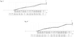
- FIG. 2 shows a schematic diagram for a heating profile of a plastic preform depending on time and energy.
- the temperature curve is shown as a function of time or the individual heating devices H1... H12.
- the heating devices H1... H3, H5, H6 and H9... H12 are set to a heating output of 80% set, while the heating devices H4, H7 and H8 are completely switched off.
- the energy or temperature of the preforms remains constant when the heating devices are switched off and in the compensation zones E1 and E2, while the temperature increases and in particular increases linearly in the heating devices H1... H3, H5, H6 and H9... H12.
- Figure 3 shows another schematic diagram for a heating profile of a plastic preform depending on time and energy.
- the course of the solid line corresponds to the Figure 2 shown course.
- the dashed line is the temperature profile of the preform with changed heating outputs of the heating devices H1...H12.
- the table below also dashed, shows that the heating devices H1 and H2 are switched off and the outputs of the heating devices H3...H12 have been changed to 70%.
- the heating power was therefore reduced compared to the solid line/table, since the plastic preforms were transported through the heating device at a lower transport speed and therefore remained longer in front of the individual heating devices.
- the diagram illustrates that despite the changed speed, an almost identical heating profile is possible over time and, in particular, an identical temperature at the end.
- Figure 4 shows another schematic diagram for a heating profile of a plastic preform depending on time and energy.
- the solid line corresponds to the Figure 2 shown course.
- the Figure 4 shows in particular another possibility of adjusting the heating output of the heating devices H1... H12, which again results in an almost identical heating profile, as shown by the dashed line.
- the associated (dashed) table shows that in this example the heating devices H1, H2, H8 and H9 are completely switched off and the remaining heating devices, unlike in the example in Figure 3 example shown, have different heating outputs.
- the heating device H3 is operated here at 30%, the heating devices H4 and H5 at 81%, the heating device H6 at 35%, the heating devices H7 and H12 at 90% and the heating devices H10 and H11 at 80%.
- the Figures 3 and 4 In particular, they illustrate that when the transport speed through the heating device is changed, almost similar temperature profiles with identical final temperatures can still be generated on the plastic preforms by using different settings of the heating power of the heating devices.
- Figure 5 shows a second schematic embodiment of a device 1 according to the invention for heating plastic preforms 10.
- the device 1 shown here essentially corresponds to the device shown in Figure 1 shown device, so that here no more reference is made to the already described Figure 1 reference number received.
- the device here also has several temperature sensors 7, which can detect an internal and/or external temperature of the plastic preforms 10.
- a temperature sensor 7 could, as in the Figure 5 can be seen, for example, also arranged on the transport star 2.
- the arrangement of the temperature sensors in the device is exemplary and not limited to this arrangement. Rather, they can be arranged at any point on the device.
- the heating device H13 is arranged so that it can be moved, as is shown by the arrows.
- the arrangement of this movable heating device is not limited to the arrangement shown. Rather, any other heating device can be arranged so that it can be moved, or the heating device can also have several movable heating devices.
Landscapes
- Engineering & Computer Science (AREA)
- Manufacturing & Machinery (AREA)
- Mechanical Engineering (AREA)
- Physics & Mathematics (AREA)
- Thermal Sciences (AREA)
- Blow-Moulding Or Thermoforming Of Plastics Or The Like (AREA)
- Processing And Handling Of Plastics And Other Materials For Molding In General (AREA)
Description
- Die vorliegende Erfindung bezieht sich auf eine Vorrichtung und ein Verfahren zum Erwärmen von Kunststoffvorformlingen. Derartige Vorrichtungen und Verfahren sind aus dem Stand der Technik seit langem bekannt, und z.B. in den Patentschriften
EP3446852A1 ,US2014/145375A1 ,EP2436507A2 undUS2020/307064A1 beschrieben. - Die Kunststoffvorformlinge werden dabei innerhalb einer Erwärmungseinrichtung wie beispielsweise einem Ofen, mit einer Vielzahl von Heizeinrichtungen auf eine vorgegebene Temperatur erwärmt. Üblicherweise handelt es sich dabei um eine für die Blasformung bzw. Umformung der Kunststoffvorformlinge zu Kunststoffbehältnissen notwendige Temperatur. Bekannte Blasformmaschinen weisen dabei eine elektrische Reckeinheit auf welche, wie aus dem internen Stand der Technik der Anmelderin bekannt ist, unterschiedliche Blasradgeschwindigkeiten bei gleichen Behälterqualitäten ermöglichen und somit variable Produktionszahlen. Eine geschwindigkeitsregelbare Blasmaschine ist dabei beispielsweise auch aus der
DE 10 2017 126 240 A1 bekannt. Auch bekannte Füllmaschinen und Etikettiermaschinen können die Geschwindigkeit variieren. - Bisher ist es allerdings nicht möglich auch die Geschwindigkeit im Ofen bei gleichbleibender Erwärmung der Kunststoffvorformlinge zu variieren, da sich beispielsweise bei langsamerer Transportgeschwindigkeit durch den Ofen die Verweildauer der Kunststoffvorformlinge im Ofen erhöhen würde und somit auch die Verweildauer der Kunststoffvorformlinge vor den einzelnen Lampen bzw. Heizeinrichtungen.
- Der vorliegenden Erfindung liegt daher die Aufgabe zugrunde eine Vorrichtung und ein Verfahren bereitzustellen, welche/welches eine Regelung der Transportgeschwindigkeit des Ofens bei gleichbleibenden Vorformlingstemperaturen am Ausgang des Ofens ermöglicht. Diese Aufgabe wird erfindungsgemäß durch die Gegenstände der unabhängigen Ansprüche erreicht. Vorteilhafte Ausführungsformen und Weiterbildungen sind Gegenstand der Unteransprüche.
- Die Erfindung ist daher auf ein Verfahren zum Erwärmen von Kunststoffvorformlingen gerichtet, wobei die Kunststoffvorformlinge innerhalb einer Erwärmungseinrichtung entlang eines vorgegebenen Transportpfads transportiert werden und während dieses Transports mittels einer Vielzahl von entlang des Transportpfads angeordneten Heizeinrichtungen auf eine vorgegebene Temperatur erwärmt werden, und wobei eine auf die Kunststoffvorformlinge auftreffende Heizleistung der Heizeinrichtungen veränderbar ist.
- Erfindungsgemäß wird die auf die Kunststoffvorformlinge auftreffende Heizleistung der Heizeinrichtungen in Abhängigkeit einer Transportgeschwindigkeit der Kunststoffvorformlinge geregelt.
- Es wird demnach erfindungsgemäß vorgeschlagen die Heizleistung jeder Heizeinrichtung bevorzugt individuell auf die Transportgeschwindigkeit der Kunststoffvorformlinge anzupassen. Insbesondere wird demnach bei langsamerer Transportgeschwindigkeit die Heizleistung der Heizeinrichtungen verringert, da die Kunststoffvorformlinge längere Zeit in der Erwärmungseinrichtung verbleiben und damit auch längere Zeit vor den einzelnen Heizeinrichtungen. Entsprechend wird bei einer höheren Transportgeschwindigkeit die Heizleistung der Heizeinrichtung erhöht, da die Zeitspanne, in welcher die Kunststoffvorformlinge in der Erwärmungseinrichtung verbleiben, kürzer ist.
- Diese Regelung der Heizleistung ist dabei insbesondere im Hinblick auf eine variable Blasmaschine, welche in Transportrichtung der Kunststoffvorformlinge gesehen, nach der Erwärmungseinrichtung angeordnet ist, vorteilhaft. Das vorgeschlagene Verfahren stellt zudem eine Regelung der Heizeinrichtungen ohne viel Regelaufwand bereit. Insbesondere kann somit auch bei einer geblockten Gesamtanlage, mit mehreren geblockten Maschinen, wie beispielsweise Erwärmungseinrichtung, Blasformmaschine, Fülleinrichtung, Verschließer, Sterilisationseinrichtung, oder dergleichen, in einfacher Weise eine variable Ausbringleistung ermöglicht werden.
- Bei dieser Vorgehensweise wird davon ausgegangen, dass die Vorformlinge bevorzugt zu einem bestimmten Zeitpunkt (t=0) in der Blasformmaschine sind bzw. in diese einlaufen und der Blasvorgang beginnt. Vorher wurden die Vorformlinge durch die Erwärmungseinrichtung transportiert und mit bestimmten Heizleistungen beaufschlagt. Dies führt, wie in den Figuren näher dargestellt ist, zu einer Heizhistorie die mit dem Start in der ersten Heizzone bzw. Heizungseinrichtung (t=SH1) beginnt und bei dem oben erwähnten bestimmten Zeitpunkt (t=0) endet, zu dem die Vorformlinge die Blasformmaschine erreichen.
- Es wird dabei vereinfacht angenommen, dass während einer Heizzone die abgestrahlte Leistung konstant ist (was eine grobe Vereinfachung ist, die aber beim Endergebnis nicht weiter ins Gewicht fällt) und somit die aufgenommen Energie der Vorformlinge vor jeder angeschalteten Heizeinrichtung linear zunimmt und vor einer ausgeschalteten Heizeinrichtungen konstant bleibt.
- Bei der Transporteinrichtung handelt es sich bevorzugt um eine umlaufende Transporteinrichtung mit geradlinigen und gekrümmten Transportabschnitten. Bevorzugt weist die Transporteinrichtung dabei einen linearen Abschnitt auf, entlang dem die Kunststoffvorformlinge einen linearen Transportpfad entlang bewegt werden. Vorteilhaft weist die Transporteinrichtung auch wenigstens einen, bevorzugt zwei, gekrümmte Abschnitte auf, wobei sich die linearen Abschnitte und die gekrümmten Abschnitte bevorzugt abwechseln.
- Bevorzugt handelt es bei wenigstens einem gekrümmten Abschnitt um eine Ausgleichszone, in welcher keine Heizeinrichtungen angeordnet sind Die Temperatur des Kunststoffvorformlings bleibt demnach in der Ausgleichszone konstant bzw. ändert sich nicht wesentlich. Bevorzugt kann es sich auch bei einem Transportrad zur Übergabe der erwärmten Kunststoffvorformlinge an die nachfolgende Blasformmaschine um eine derartige Ausgleichszone handeln, so dass die Temperatur des Kunststoffvorformlings von der letzten Heizeinrichtung bis zur Zufuhr in die Blasformmaschine (nach vereinfachter Annahme) konstant bzw. zumindest nahezu konstant bleibt.
- Wird nun die Transportgeschwindigkeit geändert, bleibt die Steigung der Energiezunahme bei einer eingeschalteten Heizeinrichtung konstant, jedoch ändert sich die Zeit, welche der Vorformling vor der Heizeinrichtung verbleibt und von dieser erwärmt wird. Um somit dieselbe Energiemenge einer Heizeinrichtung zu erreichen, muss, wie oben bereits erwähnt, bei langsamerer Geschwindigkeit die Heizleistung verringert werden und bei schnellerer Geschwindigkeit die Heizleistung entsprechend erhöht werden, um den gleichen Energieeintrag zu gewährleisten. Bevorzugt wird dabei eine Stellgröße der einzelnen Heizeinrichtungen verändert und insbesondere verringert und/oder erhöht.
- Es wird demnach vorgeschlagen die Heizeinrichtungen bzw. deren Heizleistung so zu verändern oder ein- und auszuschalten, dass bei einer Abb- bzw. Nachbildung der Heizhistorie je horizontaler Heizeinrichtung in einem Diagramm sich ein möglichst ähnlicher Energie-Zeitverlauf je Heizeinrichtung ergibt, wie bei der ursprünglichen bzw. vorherigen Einstellung der Heizleistung.
- Da typischerweise alle Lampen einer Heizeinrichtung bzw. Heizzone die gleiche Stellgröße haben, gibt es bevorzugt die Möglichkeit dies so bei zu behalten und zu versuchen mit einer gesamtheitlichen Stellgröße den Energie-Zeitverlauf nachzustellen. Vor allem die Ausgleichszonen an der Umlenkung und am Transportstern können nicht uneingeschränkt kompensiert werden. Daher ergeben sich hier häufig etwas andere Verläufe. Um dennoch einen möglichst ähnlichen Energie-Zeitverlauf zu erzeugen, kann vor diesen Zonen die Energie etwas überhöht sein und bevorzugt die Heizleistung der vor diesen Ausgleichszonen angeordneten Heizeinrichtungen höher sein. Die ähnlichen Verläufe der Heizhistorien können nach verschiedenen mathematischen Mustern stattfinden und beispielsweise die Summe kleinster Fehlerquadrate sein, oder auch der Versuch, dass die Flächen zwischen den beiden unterschiedlichen Verläufen minimal sind oder, dass am Ende jeder Heizzone der Energieverlauf identisch ist.
- Diese Anpassung kann bevorzugt in der Hauptsteuerung, in einem weiteren Edgedevice oder auch in einem cloudbasierten Optimierer vorgenommen werden. Um dem möglichen Optimum nahezukommen ist es ratsam, die Zonenleistung in einer Heizeinrichtung bzw. Heizzone zu variieren. So kann beispielsweise die Heizeinrichtung 3 nur mit 30% betrieben werden und die Heizeinrichtung 4, bevorzugt in derselben Höhe, dagegen mit 81%. Um etwas mehr Variation zu ermöglichen, kann man versuchen bei der Einstellung des Grundrezepts auf extreme Werte wie z.B. über 95% zu verzichten, oder auf Randheizkästen zu verzichten.
- Durch die Regelung der Erwärmungseinrichtung wird bevorzugt zudem eine variable Blasformmaschine ermöglicht. Bevorzugt kann demnach die Transportgeschwindigkeit in der Erwärmungseinrichtung erhöht werden, wenn die Ausbringrate der Blasformmaschine erhöht werden soll. Entsprechend kann dabei auch die Geschwindigkeit der Blasformmaschine an die Geschwindigkeit der Erwärmungseinrichtung angepasst werden oder der Blasprozess in der Blasformmaschine entsprechend verändert werden.
- Bei einem bevorzugten Verfahren wird demnach die Heizleistung jeder Heizeinrichtung und/oder insbesondere auch benachbarter Heizeinrichtungen individuell und/oder unabhängig voneinander geregelt und/oder verändert. Bevorzugt kann demnach die Heizleistung jeder Heizeinrichtung unabhängig von der Heizleistung der anderen Heizeinrichtungen individual geregelt werden, so dass die Heizleistung derart auf die jeweilige Transportgeschwindigkeit angepasst werden kann, so dass das auf die Kunststoffvorformlinge aufzubringende Temperaturprofil unabhängig von der Transportgeschwindigkeit stets gleich ist. Jede Heizeinrichtung bildet dabei bevorzugt eine eigenständige und unabhängige Heizzone aus.
- Bei einem weiteren bevorzugten Verfahren wird die Heizleistung der Heizeinrichtungen und/oder die Transportgeschwindigkeit der Kunststoffvorformlinge stufenlos geregelt. Dies bedeutet, dass beispielsweise die Heizleistung der Heizeinrichtung auf jeden beliebigen Wert zwischen einer Heizleistung von 0% und 100% einstellbar ist. Bevorzugt kann auch ein bestimmter Bereich vorgegeben werden innerhalb dem jeder beliebige Wert einstellbar ist, wie beispielsweise ein Bereich von 10% - 85%. Durch diese stufenlose Regelung wird vorteilhaft eine sehr genaue und feine Einstellung der Heizleistung ermöglicht.
- In einem weiteren bevorzugten Verfahren ist wenigstens eine Heizeinrichtung und sind bevorzugt mehrere Heizeinrichtungen entlang des Transportpfads der Erwärmungseinrichtung verschiebbar angeordnet. Bevorzugt wird die wenigstens eine Heizeinrichtung entlang des linearen Transportabschnitts verschoben bzw. ist entlang des linearen Transportabschnitts verschiebbar angeordnet. Besonders bevorzugt ist wenigstens die Heizeinrichtung verschiebbar, welche die Kunststoffvorformlinge als letztes erwärmt bzw. welche direkt vor der Ausgleichszone des Transportsterns oder in Transportrichtung der Kunststoffvorformlinge gesehen, am Ende der Transporteinrichtung angeordnet ist.
- Denkbar wäre auch, dass eine oder mehrere an anderen Stellen der Transporteinrichtung angeordneten Heizeinrichtungen verschiebbar angeordnet sind, wie beispielsweise die erste Heizeinrichtung und/oder die vor und/oder nach der Ausgleichszone des gekrümmten Transportabschnitts angeordneten Heizeinrichtungen. Durch verschiebbare Heizeinrichtungen kann insbesondere der Abstand zu benachbarten Heizeinrichtungen eingestellt werden und auch der Abschnitt auf der Transporteinrichtung wann ein bestimmtes und/oder endgültiges Temperaturprofil auf den Kunststoffvorformling aufgebracht wird individuell bestimmt werden.
- Bei einem bevorzugten Verfahren wird innerhalb der Erwärmungseinrichtung eine Innen- und/oder Außentemperatur der Kunststoffvorformlinge erfasst und diese Temperatur zur Regelung der Heizleistung der Heizeinrichtungen herangezogen. Bevorzugt ist hierzu wenigstens ein Temperatursensor und besonders bevorzugt mehrere Temperatursensoren innerhalb der Erwärmungseinrichtung angeordnet.
- Bevorzugt ermitteln die Temperatursensoren dabei die Außen- und/oder Innentemperatur der Vorformlinge an einem oder mehreren Orten, um Rückschlüsse auf die Heizhistorie zu erhalten. Bevorzugt kann auch basierend auf diesen Daten eine überlagerte Regelung/Steuerung die Heizparameter anpassen. Bei den Temperatursensoren kann es sich bevorzugt, allerdings nicht ausschließlich, um Pyrometer oder IR-Kameras handeln. Diese können zur Variation des Messpunkts vorteilhaft geschwenkt werden. Alternativ kann der Messpunkt auch über Spiegel variiert werden.
- Auch wäre es denkbar, dass die Anpassung der Heizleistung basierend auf einem anderen Regelkonzept vorgenommen wird, welches auf einer Temperatur der Vorformlinge und/oder einer Wandstärkeinformationen der Behälter (oder auch anderen Behälterkennwerte wie Topload ect...) auf einem Neuronalen Netz oder Maschine Learning Modell basiert.
- Bei einem bevorzugten Verfahren wird die Heizleistung über wenigstens ein erstes Eckrezept und ein zweites Eckrezept geregelt und bevorzugt linear interpoliert, wobei das erste Eckrezept eine erste Heizleistung enthält und das zweite Eckrezept eine zweite Heizleistung. Demnach ist auch eine Anpassung der Leistung über zwei Eckpunkte denkbar und beispielsweise über eine Verbindung mehrerer Regelungs/Steuerungs-Algorithmen. So ist es beispielsweise denkbar, dass ein Rezept bei 95% Nenngeschwindigkeit eingestellt wird, dieses dann nach der Logik der Heizhistorie auf z.B. 75% gerechnet wird, dann das 75% Rezept nochmal manuell leicht angepasst wird und dann beide Modelle vereint werden um Rezepte von 100% -70% einzustellen.
- Darüber hinaus können bevorzugt noch weitere Werte angepasst werden. Beispielsweise wäre es denkbar, neben der Heizleistung auch die Ventilation anzupassen. Weiterhin könnte, um die fehlende Heizleistung in der Umlenkung bzw. dem gekrümmten Abschnitt zu kompensieren, auch ein zusätzlicher Heizkasten in dem gekrümmten Abschnitt angeordnet sein.
- Bevorzugt wäre auch eine Vortemperierung der Vorformlinge denkbar, welche die unterschiedlichen Heizhistorien etwas angleicht. Die Logik der angepassten Heizhistorie kann sich auf jede horizontale Heizzone bzw. Heizeinrichtung einzeln beziehen, wobei vorteilhaft auch rechnerisch Heizzonen unterschiedlicher Höhen, z.B. Nachbarheizzonen miteinander kombiniert werden können.
- Da die Temperatur in den Ausgleichzonen nicht so einfach ausgeglichen werden kann wie in den Heizeinrichtungen wäre es denkbar, dass die Vorformlinge hier nicht mit einer Kette mit festen Teilungen transportiert werden, sondern bevorzugt mit einzelnen variablen Werkstückträgern (LLM), um so die Durchfahrtgeschwindigkeit durch bestimmte Zonen bzw. Abschnitte variieren zu können und demnach die Heizhistorie besser anpassen zu können.
- Die vorliegende Erfindung ist weiterhin auch auf eine Vorrichtung zum Erwärmen von Kunststoffvorformlingen gerichtet, mit einer Erwärmungseinrichtung innerhalb derer die Kunststoffvorformlinge mittels einer Transporteinrichtung entlang eines vorgegebenen Transportpfads transportiert werden, wobei die Kunststoffvorformlinge während des Transports mittels einer Vielzahl von entlang des Transportpfads angeordneten Heizeinrichtungen auf eine vorgegebene Temperatur erwärmbar sind, wobei eine auf die Kunststoffvorformlinge auftreffende Heizleistung der Heizeinrichtungen veränderbar ist.
- Erfindungsgemäß weist die Vorrichtung eine Steuerungs- und/oder Regelungseinrichtung auf, welche die auf die Kunststoffvorformlinge auftreffende Heizleistung der Heizeinrichtungen in Abhängigkeit einer Transportgeschwindigkeit der Kunststoffvorformlinge regelt.
- Es wird demnach auch vorrichtungsseitig vorgeschlagen die Heizleistung jeder Heizeinrichtung bevorzugt individuell auf die Transportgeschwindigkeit der Kunststoffvorformlinge anzupassen und insbesondere bei langsamerer Transportgeschwindigkeit die Heizleistung der Heizeinrichtungen zu verringern und bei höherer Transportgeschwindigkeit die Heizleistung der Heizeinrichtungen zu erhöhen.
- Bei einer bevorzugten Ausführungsform weist die Erwärmungseinrichtung wenigstens einen und bevorzugt eine Vielzahl von Temperatursensoren auf, welche eine Innen- und/oder eine Außentemperatur der Kunststoffvorformlinge erfassen. Wie oben bereits erwähnt, ermitteln die Temperatursensoren dabei bevorzugt die Außen- und/oder Innentemperatur der Vorformlinge an einem oder mehreren Orten, um hieraus Rückschlüsse auf die Heizhistorie zu erhalten.
- Bei einer weiteren bevorzugten Ausführungsform ist daher die Heizleistung der Heizeinrichtungen in Abhängigkeit der von den Temperatursensoren erfassten Temperatur regelbar. Weisen die Vorformlinge demnach beispielswiese an einem bestimmten Abschnitt des Transportpfades eine zu geringe Temperatur auf, wird die Heizleistung einer oder mehrerer Heizeinrichtungen entsprechend erhöht.
- In einer weiteren bevorzugten Ausführungsform sind an wenigstens einem Abschnitt des Transportpfads der Erwärmungseinrichtung keine Heizeinrichtungen angeordnet. Bevorzugt handelt es sich dabei um die gekrümmten Abschnitte des Transportpfads.
- Bei einer bevorzugten Ausführungsform sind die Heizeinrichtungen aus einer Gruppe von Heizeinrichtungen ausgewählt, welche IR-Lampen, Mikrowellenerwärmungseinrichtungen, Laserarrays und dergleichen enthält.
- Die Vorrichtung umfasst bevorzugt auch eine oder mehrere weitere Einrichtungen, wie beispielsweise eine Fülleinrichtung zum Befüllen von Behältnissen, eine Verschließeinrichtung zum Verschließen der Behältnisse, eine Sterilisationseinrichtung zum Sterilisieren von Vorformlingen und/oder Behältnissen, oder dergleichen. Bevorzugt sind dabei aller Einrichtungen miteinander geblockt bzw. aufeinander synchronisiert, so dass bevorzugt auch eine blockübergreifende Regelung denkbar ist, die beispielsweise abhängig von der maximal möglichen Füllgeschwindigkeit die Leitgeschwindigkeit ist.
- Weiterhin ist die vorliegende Erfindung auch auf eine Anlage zum Erwärmen von Kunststoffvorformlingen gerichtet, mit einer Transporteinrichtung, welche die Kunststoffvorformlinge entlang eines vorgegebenen Transportpfades transportiert, wobei die Kunststoffvorformlinge während des Transports mittels einer Vielzahl von entlang des Transportpfads angeordneten Heizeinrichtungen auf eine vorgegebene Temperatur erwärmbar sind, und wobei stromabwärts der Anlage zum Erwärmen eine Umformungseinrichtung zum Umformen von Kunststoffvorformlingen zu Kunststoffbehältnissen angeordnet ist.
- Erfindungsgemäß weist die Anlage eine Steuerungs- und/oder Regelungseinrichtung auf, welche die auf die Kunststoffvorformlinge auftreffende Heizleistung der Heizeinrichtungen in Abhängigkeit einer Transportgeschwindigkeit der Kunststoffvorformlinge regelt und/oder in Abhängigkeit von dieser Transportgeschwindigkeit die Umformungseinrichtung steuerbar und/oder regelbar ist.
- Auch diese Anlage umfasst dabei bevorzugt eine oder mehrere weitere Einrichtungen, wie beispielsweise eine Fülleinrichtung zum Befüllen von Behältnissen, eine Verschließeinrichtung zum Verschließen der Behältnisse, eine Sterilisationseinrichtung zum Sterilisieren von Vorformlingen und/oder Behältnissen, oder dergleichen, welche miteinander verblockt und/oder aufeinander synchronisiert sind, so dass eine blockübergreifende Regelung möglich ist.
- Weitere Vorteile und Ausführungsformen ergeben sich aus den beigefügten Zeichnungen.
- Darin zeigt:
- Fig. 1
- eine erste schematische Ausführungsform einer erfindungsgemäßen Vorrichtung zum Erwärmen von Kunststoffvorformlingen;
- Fig. 2
- ein schematisches Diagramm für ein Heizprofil eines Kunststoffvorformlings in Abgängigkeit von Zeit und Energie;
- Fig. 3
- ein weiteres schematisches Diagramm für ein Heizprofil eines Kunststoffvorformlings in Abgängigkeit von Zeit und Energie;
- Fig. 4
- ein weiteres schematisches Diagramm für ein Heizprofil eines Kunststoffvorformlings in Abgängigkeit von Zeit und Energie; und
- Fig. 5
- eine zweite schematische Ausführungsform einer erfindungsgemäßen Vorrichtung zum Erwärmen von Kunststoffvorformlingen.
-
Figur 1 zeigt eine erste schematische Ausführungsform einer erfindungsgemäßen Vorrichtung 1 zum Erwärmen von Kunststoffvorformlingen 10. Die Vorrichtung 1 weist in diesem Ausführungsbeispiel eine Erwärmungseinrichtung 5 und eine Umformungseinrichtung 6 auf. Die innerhalb der Erwärmungseinrichtung 5 erwärmten Kunststoffvorformlinge 10 werden dabei mittels eines Transportsterns 12 an die Umformungseinrichtung 6 übergeben. - Die Kunststoffvorformlinge 10 werden dabei mit einer Transporteinrichtung 2 entlang eines vorgegebenen Transportpfades T durch die Erwärmungseinrichtung 5 transportiert und während des Transports mit einer Vielzahl von entlang des Transportpfades T angeordneten Heizeinrichtungen H1 ... H12 auf eine vorgegebene Temperatur erwärmt. Die Transporteinrichtung 2 weist hierzu eine Vielzahl von (nicht gezeigten) Halteeinrichtungen zum Halten der Kunststoffvorformlinge auf.
- Das Bezugszeichen 3 kennzeichnet eine Steuerungs- und/oder Regelungseinrichtung, zum Regeln bzw. Verändern einer Heizleistung der Heizeinrichtungen H1... H12. Weiterhin ist erkennbar, dass innerhalb eines gekrümmten Abschnitts der Transporteinrichtung 2, bei welchem es sich bevorzugt um eine Ausgleichszone E1 handelt keine Heizeinrichtungen angeordnet sind. Weiterhin bildet der Transportstern 12 eine zweite derartige Ausgleichszone E2 aus. Die Temperatur der Kunststoffvorformlinge 10 bleibt in den Ausgleichszonen E1, E2 bevorzugt konstant bzw. ändert sich zumindest nicht wesentlich.
-
Figur 2 zeigt ein schematisches Diagramm für ein Heizprofil eines Kunststoffvorformlings in Abgängigkeit von Zeit und Energie. Dargestellt ist dabei der Temperaturverlauf in Abhängigkeit von der Zeit bzw. den einzelnen Heizeinrichtungen H1... H12. Die Heizeinrichtungen H1... H3, H5, H6 und H9... H12 sind dabei in diesem Beispiel auf eine Heizleistung von 80% eingestellt, während die Heizeinrichtungen H4, H7 und H8 komplett ausgeschalten sind. Erkennbar ist dabei auch, dass die Energie bzw. Temperatur der Vorformlinge bei den ausgeschalteten Heizeinrichtungen sowie den Ausgleichszonen E1 und E2 konstant bleibt, während die Temperatur bei den Heizeinrichtungen H1... H3, H5, H6 und H9... H12 zunimmt und insbesondere linear ansteigt. - Der Zeitpunkt t=0 kennzeichnet dabei den Zeitpunkt, zu dem der erwärmte Kunststoffvorformling an die Blasformmaschine übergeben wird und der Zeitpunkt t=SH1 den Zeitpunkt, an dem sich der Vorformling an der ersten Heizeinrichtung H1 befindet. Entsprechend kennzeichnet der Zeitpunkt t=SH2 den Zeitpunkt, an dem sich der Vorformling an der zweiten Heizeinrichtung H2 befindet.
-
Figur 3 zeigt ein weiteres schematisches Diagramm für ein Heizprofil eines Kunststoffvorformlings in Abgängigkeit von Zeit und Energie. Der Verlauf der durchgezogenen Linie entspricht dabei dem inFigur 2 gezeigten Verlauf. - Bei der gestrichelten Linie handelt es sich um das Temperaturprofil des Vorformlings mit veränderten Heizleistungen der Heizeinrichtungen H1...H12. Aus der unteren, ebenfalls gestrichelten Tabelle geht dabei hervor, dass die Heizeinrichtungen H1 und H2 ausgeschalten sind und die Leistungen der Heizeinrichtungen H3... H 12 auf 70% verändert wurde.
- Die Heizleistung wurde demnach im Vergleich zu der durchgezogenen Linie/Tabelle verringert, da die Kunststoffvorformlinge mit einer geringeren Transportgeschwindigkeit durch die Erwärmungseinrichtung transportiert wurden und demnach länger vor den einzelnen Heizeinrichtungen verweilen.
- Das Diagramm veranschaulicht dabei, dass trotz der veränderten Geschwindigkeit ein annähernd gleiches Heizprofil über die Zeit ermöglicht wird sowie insbesondere eine identische Temperatur am Ende.
-
Figur 4 zeigt ein weiteres schematisches Diagramm für ein Heizprofil eines Kunststoffvorformlings in Abgängigkeit von Zeit und Energie. Auch hier entspricht die durchgezogene Line wieder dem inFigur 2 gezeigten Verlauf. - Die
Figur 4 zeigt dabei insbesondere eine weitere Möglichkeit der Anpassung der Heizleistungen der Heizeinrichtungen H1... H12, bei welcher jedoch wieder ein annähernd gleiches Heizprofil entsteht, wie durch die gestrichelte Linie verdeutlicht wird. Aus der zugehörigen (gestrichelten) Tabelle geht dabei hervor, dass in diesem Beispiel die Heizeinrichtungen H1, H2, H8 und H9 komplett ausgeschalten sind und die restlichen Heizeinrichtungen, anders als in dem inFigur 3 gezeigten Beispiel, unterschiedliche Heizleistungen aufweisen. Die Heizeinrichtung H3 wird hier mit 30% betrieben, die Heizeinrichtungen H4 und H5 mit 81%, die Heizeinrichtung H6 mit 35%, die Heizeinrichtungen H7 und H12 mit 90% und die Heizeinrichtungen H10 und H11 mit 80%. - Die
Figuren 3 und 4 veranschaulichen dabei insbesondere, dass bei einer Änderung der Transportgeschwindigkeit durch die Erwärmungseinrichtung durch unterschiedliche Einstellungen der Heizleistungen der Heizeinrichtungen trotzdem nahezu ähnliche Temperaturprofile, mit identischer End-Temperatur auf den Kunststoffvorformlingen erzeugt werden können. -
Figur 5 zeigt eine zweite schematische Ausführungsform einer erfindungsgemäßen Vorrichtung 1 zum Erwärmen von Kunststoffvorformlingen 10. Die hier gezeigte Vorrichtung 1 entspricht dabei im Wesentlichen der inFigur 1 gezeigten Vorrichtung, so dass hier nicht mehr auf die bereits im Rahmen der Beschreibung derFigur 1 eingegangenen Bezugszeichen verwiesen wird. - Anders als in der in
Figur 1 gezeigten Ausführungsform weist die Vorrichtung hier jedoch zudem mehrere Temperatursensoren 7 auf, welche eine Innen- und/oder Außentemperatur der Kunststoffvorformlinge 10 erfassen können. Ein derartiger Temperatursensor 7 könnte dabei, wie in derFigur 5 erkennbar ist, beispielsweise auch an dem Transportstern 2 angeordnet sein. Die Anordnung der Temperatursensoren in der Vorrichtung ist dabei beispielhaft und nicht auf diese Anordnung begrenzt. Vielmehr können diese an jeder beliebigen Stelle der Vorrichtung angeordnet sein. - Weiterhin ist in der
Figur 5 die Heizeinrichtung H13 verschiebbar angeordnet, wie durch die Pfeile verdeutlicht wird. Auch die Anordnung dieser verschiebbaren Heizeinrichtung ist dabei nicht auf diese gezeigte Anordnung beschränkt. Vielmehr kann jede andere Heizeinrichtung verschiebbar angeordnet werden oder die Erwärmungseinrichtung kann auch mehrere verschiebbare Heizeinrichtungen aufweisen. -
- 1
- Vorrichtung
- 2
- Transporteinrichtung
- 3
- Steuerungs- und/oder Regelungseinrichtung
- 5
- Erwärmungseinrichtung
- 6
- Umformungseinrichtung
- 7
- Temperatursensor
- 10
- Kunststoffvorformlinge
- 12
- Transportrad
- E1, E2
- Ausgleichszone
- H1... H13
- Heizeinrichtungen
- T
- Transportpfad
Claims (11)
- Verfahren zum Erwärmen von Kunststoffvorformlingen (10), wobei die Kunststoffvorformlinge innerhalb einer Erwärmungseinrichtung (5) entlang eines vorgegebenen Transportpfads (T) transportiert werden und während dieses Transports mittels einer Vielzahl von entlang des Transportpfads (T) angeordneten Heizeinrichtungen (H1... H12) auf eine vorgegebene Temperatur erwärmt werden, und wobei eine auf die Kunststoffvorformlinge (10) auftreffende Heizleistung der Heizeinrichtungen (H1 ... H12) veränderbar ist,
dadurch gekennzeichnet, dassdie auf die Kunststoffvorformlinge (10) auftreffende Heizleistung der Heizeinrichtungen (H1 ... H12) in Abhängigkeit einer Transportgeschwindigkeit der Kunststoffvorformlinge (10) geregelt wird,wobei die Heizleistung jeder Heizeinrichtung (H1 ... H12) und/oder insbesondere auch benachbarter Heizeinrichtungen (H1... H12) individuell und/oder unabhängig voneinander geregelt und/oder verändert wird. - Verfahren nach Anspruch 1,
dadurch gekennzeichnet, dass
die Heizleistung der Heizeinrichtungen (H1 ... H12) und/oder die Transportgeschwindigkeit der Kunststoffvorformlinge (10) stufenlos geregelt wird. - Verfahren nach Anspruch 1,
dadurch gekennzeichnet, dass
wenigstens eine Heizeinrichtung (H1... H12) und bevorzugt mehrere Heizeinrichtungen (H1... H12) entlang des Transportpfads (T) der Erwärmungseinrichtung (5) verschiebbar angeordnet sind. - Verfahren nach Anspruch 1,
dadurch gekennzeichnet, dass
innerhalb der Erwärmungseinrichtung (5) eine Innen- und/oder Außentemperatur der Kunststoffvorformlinge (10) erfasst wird und diese Temperatur zur Regelung der Heizleistung der Heizeinrichtungen (H1... H12) herangezogen wird. - Verfahren nach Anspruch 1,
dadurch gekennzeichnet, dass
die Heizleistung über wenigstens ein erstes und ein zweites Eckrezept geregelt und bevorzugt linear interpoliert wird, wobei das erste Eckrezept eine erste Heizleistung enthält und das zweite Eckrezept eine zweite Heizleistung. - Vorrichtung (1) zum Erwärmen von Kunststoffvorformlingen (10), mit einer Erwärmungseinrichtung (5), innerhalb derer die Kunststoffvorformlinge (10) mittels einer Transporteinrichtung (2) entlang eines vorgegebenen Transportpfads (T) transportiert werden, wobei die Kunststoffvorformlinge (10) während des Transports mittels einer Vielzahl von entlang des Transportpfads (T) angeordneten Heizeinrichtungen (H1... H12) auf eine vorgegebene Temperatur erwärmbar sind, wobei eine auf die Kunststoffvorformlinge (10) auftreffende Heizleistung der Heizeinrichtungen (H1 ... H12) veränderbar ist,
dadurch gekennzeichnet, dass
die Vorrichtung (1) eine Steuerungs- und/oder Regelungseinrichtung (3) aufweist, welche die auf die Kunststoffvorformlinge (10) auftreffende Heizleistung der Heizeinrichtungen (H1... H12) in Abhängigkeit einer Transportgeschwindigkeit der Kunststoffvorformlinge (10) regelt, wobei die Heizleistung jeder Heizeinrichtung (H1...H12) und/oder insbesondere auch benachbarter Heizeinrichtungen (H1... H12) individuell und/oder unabhängig voneinander regelbar und/oder veränderbar ist. - Vorrichtung (1) nach Anspruch 6,
dadurch gekennzeichnet, dass
die Erwärmungseinrichtung (5) wenigstens einen und bevorzugt eine Vielzahl von Temperatursensoren (7) aufweist, welche eine Innen- und/oder eine Außentemperatur der Kunststoffvorformlinge (10) erfasst. - Vorrichtung (1) nach Anspruch 7,
dadurch gekennzeichnet, dass
die Heizleistung der Heizeinrichtungen (H1... H12) in Abhängigkeit der von den Temperatursensoren (7) erfassten Temperatur regelbar ist. - Vorrichtung (1) nach Anspruch 6,
dadurch gekennzeichnet, dass
an wenigstens einem Abschnitt des Transportpfads (T) der Erwärmungseinrichtung (5) keine Heizeinrichtungen (H1... H12) angeordnet sind. - Vorrichtung (1) nach Anspruch 6,
dadurch gekennzeichnet, dass
die Heizeinrichtungen (H1... H12) aus einer Gruppe von Heizeinrichtungen ausgewählt sind, welche IR-Lampen, Mikrowellenerwärmungseinrichtungen, Laserarrays und dergleichen enthält. - Anlage zum Erwärmen von Kunststoffvorformlingen (10), mit einer Transporteinrichtung (2), welche die Kunststoffvorformlinge (10) entlang eines vorgegebenen Transportpfades (T) transportiert, wobei die Kunststoffvorformlinge (10) während des Transports mittels einer Vielzahl von entlang des Transportpfads (T) angeordneten Heizeinrichtungen (H1... H12) auf eine vorgegebene Temperatur erwärmbar sind, und wobei stromabwärts der Anlage zum Erwärmen eine Umformungseinrichtung (6) zum Umformen von Kunststoffvorformlingen (10) zu Kunststoffbehältnissen angeordnet ist,
dadurch gekennzeichnet, dassdie Anlage eine Steuerungs- und/oder Regelungseinrichtung (3) aufweist, welche die auf die Kunststoffvorformlinge (10) auftreffende Heizleistung der Heizeinrichtungen (H1... H12) in Abhängigkeit einer Transportgeschwindigkeit der Kunststoffvorformlinge (10) regelt und/oder in Abhängigkeit von dieser Transportgeschwindigkeit die Umformungseinrichtung (6) steuerbar und/oder regelbar ist,wobei die Heizleistung jeder Heizeinrichtung (H1... H12) und/oder insbesondere auch benachbarter Heizeinrichtungen (H1... H12) individuell und/oder unabhängig voneinander regelbar und/oder veränderbar ist.
Applications Claiming Priority (1)
| Application Number | Priority Date | Filing Date | Title |
|---|---|---|---|
| DE102021132983.3A DE102021132983A1 (de) | 2021-12-14 | 2021-12-14 | Vorrichtung und Verfahren zum Erwärmen von Kunststoffvorformlingen mit Anpassung der Heizleistung |
Publications (2)
| Publication Number | Publication Date |
|---|---|
| EP4197740A1 EP4197740A1 (de) | 2023-06-21 |
| EP4197740B1 true EP4197740B1 (de) | 2024-12-18 |
Family
ID=84463293
Family Applications (1)
| Application Number | Title | Priority Date | Filing Date |
|---|---|---|---|
| EP22212218.6A Active EP4197740B1 (de) | 2021-12-14 | 2022-12-08 | Vorrichtung und verfahren zum erwärmen von kunststoffvorformlingen mit anpassung der heizleistung |
Country Status (4)
| Country | Link |
|---|---|
| US (1) | US20230182369A1 (de) |
| EP (1) | EP4197740B1 (de) |
| CN (1) | CN116262376A (de) |
| DE (1) | DE102021132983A1 (de) |
Families Citing this family (3)
| Publication number | Priority date | Publication date | Assignee | Title |
|---|---|---|---|---|
| JP7666697B1 (ja) | 2023-12-12 | 2025-04-22 | 大日本印刷株式会社 | ブロー成形機の動作条件推論装置,方法およびプログラム,ならびに学習装置 |
| DE102024119901A1 (de) * | 2024-07-12 | 2026-01-15 | Krones Aktiengesellschaft | Anlage zum Herstellen und Behandeln von Behältern |
| CN120491706B (zh) * | 2025-05-14 | 2026-02-06 | 三力五金机械制品(深圳)有限公司 | 一种送料机器的加热控制方法、控制装置、送料机器 |
Family Cites Families (6)
| Publication number | Priority date | Publication date | Assignee | Title |
|---|---|---|---|---|
| EP0305699B1 (de) * | 1987-09-03 | 1990-10-03 | HERMANN BERSTORFF Maschinenbau GmbH | Einrichtung zum drehbaren Transportieren von Vorformlingen durch eine Aufheizstation zu einer Streckblasmaschine |
| DE102010047104A1 (de) * | 2010-10-01 | 2012-04-05 | Krones Aktiengesellschaft | Vorrichtung zum Umformen von Kunststoffvorformlingen zu Kunststoffbehältnissen mit variabler Ausstoßleistung |
| FR2976841B1 (fr) * | 2011-06-23 | 2013-08-02 | Sidel Participations | Procede de chauffe d'une ebauche de recipient a faible temperature de paroi externe |
| FR3070300B1 (fr) * | 2017-08-24 | 2019-08-16 | Sidel Participations | Installation et procede de production de recipients, permettant de produire des le demarrage |
| DE102017119492A1 (de) * | 2017-08-25 | 2019-02-28 | Krones Ag | Verfahren und Vorrichtung zum Erwärmen von Kunststoffvorformlingen |
| DE102017126240A1 (de) | 2017-11-09 | 2019-05-09 | Krones Ag | Verfahren und Vorrichtung zum Behandeln von Kunststoffbehältnissen mit geschwindigkeitsregelbarer Blasmaschine |
-
2021
- 2021-12-14 DE DE102021132983.3A patent/DE102021132983A1/de active Pending
-
2022
- 2022-11-22 CN CN202211488736.9A patent/CN116262376A/zh active Pending
- 2022-12-08 EP EP22212218.6A patent/EP4197740B1/de active Active
- 2022-12-13 US US18/080,603 patent/US20230182369A1/en active Pending
Also Published As
| Publication number | Publication date |
|---|---|
| EP4197740A1 (de) | 2023-06-21 |
| DE102021132983A1 (de) | 2023-06-15 |
| US20230182369A1 (en) | 2023-06-15 |
| CN116262376A (zh) | 2023-06-16 |
Similar Documents
| Publication | Publication Date | Title |
|---|---|---|
| EP2390083B1 (de) | Verfahren und Vorrichtung zur Temperatursteuerung und/oder -regelung einer Heizvorrichtung für Vorformlinge | |
| EP4197740A1 (de) | Vorrichtung und verfahren zum erwärmen von kunststoffvorformlingen mit anpassung der heizleistung | |
| EP2436507B1 (de) | Vorrichtung und Verfahren zum Umformen von Kunststoffvorformlingen zu Kunststoffbehältnissen mit variabler Ausstoßleistung | |
| EP3672779B1 (de) | Verfahren und vorrichtung zum erwärmen von kunststoffvorformlingen | |
| EP2081752B1 (de) | Verfahren und vorrichtung zur blasformung von behältern | |
| EP3964348B1 (de) | Vorrichtung und verfahren zum erwärmen von kunststoffvorformlingen mit ortsaufgelöster temperaturerfassung | |
| EP3706977B1 (de) | Verfahren und vorrichtung zum behandeln von kunststoffbehältnissen mit geschwindigkeitsregelbarer blasmaschine | |
| EP2352633A2 (de) | Verfahren und vorrichtung zur blasformung von behältern | |
| EP2441563B1 (de) | Vorrichtung und Verfahren zum Herstellen von Kunststoffbehältnissen mit variabler Stationsabschaltung | |
| EP3964349A1 (de) | Vorrichtung und verfahren zum erwärmen von kunststoffvorformlingen mit ortsaufgelöster temperaturerfassung | |
| EP3681691B1 (de) | Heizvorrichtung für die temperaturkonditionierung von vorformlingen und verfahren zum betreiben einer solchen heizvorrichtung | |
| EP3095582A1 (de) | Vorrichtung und verfahren zum erwärmen von kunststoffvorformlingen mit entkoppelten transporteinrichtungen | |
| EP3088162B1 (de) | Vorrichtung und verfahren zum erwärmen von kunststoffvorformlingen mittels mikrowellen mit anpassbarem bodenreflektor | |
| EP3102384B1 (de) | Verfahren und vorrichtung zum temperieren von vorformlingen | |
| EP3095581B1 (de) | Vorrichtung und verfahren zum erwärmen von kunststoffvorformlingen mit wegstellbarer bewegungseinrichtung | |
| EP3002068A1 (de) | Walzstraße mit modellgestützter Vorsteuerung für Kühlpausen | |
| EP4241960A1 (de) | Betriebsverfahren für eine heizvorrichtung für die temperaturkonditionierung von vorformlingen in einer startupphase, heizvorrichtung und maschine |
Legal Events
| Date | Code | Title | Description |
|---|---|---|---|
| PUAI | Public reference made under article 153(3) epc to a published international application that has entered the european phase |
Free format text: ORIGINAL CODE: 0009012 |
|
| STAA | Information on the status of an ep patent application or granted ep patent |
Free format text: STATUS: THE APPLICATION HAS BEEN PUBLISHED |
|
| AK | Designated contracting states |
Kind code of ref document: A1 Designated state(s): AL AT BE BG CH CY CZ DE DK EE ES FI FR GB GR HR HU IE IS IT LI LT LU LV MC ME MK MT NL NO PL PT RO RS SE SI SK SM TR |
|
| STAA | Information on the status of an ep patent application or granted ep patent |
Free format text: STATUS: REQUEST FOR EXAMINATION WAS MADE |
|
| 17P | Request for examination filed |
Effective date: 20231201 |
|
| RBV | Designated contracting states (corrected) |
Designated state(s): AL AT BE BG CH CY CZ DE DK EE ES FI FR GB GR HR HU IE IS IT LI LT LU LV MC ME MK MT NL NO PL PT RO RS SE SI SK SM TR |
|
| GRAP | Despatch of communication of intention to grant a patent |
Free format text: ORIGINAL CODE: EPIDOSNIGR1 |
|
| STAA | Information on the status of an ep patent application or granted ep patent |
Free format text: STATUS: GRANT OF PATENT IS INTENDED |
|
| RIC1 | Information provided on ipc code assigned before grant |
Ipc: B29L 31/00 20060101ALN20240506BHEP Ipc: B29K 67/00 20060101ALN20240506BHEP Ipc: B29C 49/78 20060101ALN20240506BHEP Ipc: B29C 49/68 20060101ALN20240506BHEP Ipc: B29C 49/64 20060101AFI20240506BHEP |
|
| INTG | Intention to grant announced |
Effective date: 20240523 |
|
| GRAJ | Information related to disapproval of communication of intention to grant by the applicant or resumption of examination proceedings by the epo deleted |
Free format text: ORIGINAL CODE: EPIDOSDIGR1 |
|
| STAA | Information on the status of an ep patent application or granted ep patent |
Free format text: STATUS: REQUEST FOR EXAMINATION WAS MADE |
|
| GRAS | Grant fee paid |
Free format text: ORIGINAL CODE: EPIDOSNIGR3 |
|
| STAA | Information on the status of an ep patent application or granted ep patent |
Free format text: STATUS: GRANT OF PATENT IS INTENDED |
|
| GRAP | Despatch of communication of intention to grant a patent |
Free format text: ORIGINAL CODE: EPIDOSNIGR1 |
|
| INTC | Intention to grant announced (deleted) | ||
| RIC1 | Information provided on ipc code assigned before grant |
Ipc: B29L 31/00 20060101ALN20240923BHEP Ipc: B29K 67/00 20060101ALN20240923BHEP Ipc: B29C 49/78 20060101ALN20240923BHEP Ipc: B29C 49/68 20060101ALN20240923BHEP Ipc: B29C 49/64 20060101AFI20240923BHEP |
|
| GRAA | (expected) grant |
Free format text: ORIGINAL CODE: 0009210 |
|
| STAA | Information on the status of an ep patent application or granted ep patent |
Free format text: STATUS: THE PATENT HAS BEEN GRANTED |
|
| INTG | Intention to grant announced |
Effective date: 20241021 |
|
| AK | Designated contracting states |
Kind code of ref document: B1 Designated state(s): AL AT BE BG CH CY CZ DE DK EE ES FI FR GB GR HR HU IE IS IT LI LT LU LV MC ME MK MT NL NO PL PT RO RS SE SI SK SM TR |
|
| REG | Reference to a national code |
Ref country code: CH Ref legal event code: EP |
|
| REG | Reference to a national code |
Ref country code: DE Ref legal event code: R096 Ref document number: 502022002429 Country of ref document: DE |
|
| REG | Reference to a national code |
Ref country code: IE Ref legal event code: FG4D Free format text: LANGUAGE OF EP DOCUMENT: GERMAN |
|
| P01 | Opt-out of the competence of the unified patent court (upc) registered |
Free format text: CASE NUMBER: APP_1779/2025 Effective date: 20250110 |
|
| REG | Reference to a national code |
Ref country code: LT Ref legal event code: MG9D |
|
| PG25 | Lapsed in a contracting state [announced via postgrant information from national office to epo] |
Ref country code: HR Free format text: LAPSE BECAUSE OF FAILURE TO SUBMIT A TRANSLATION OF THE DESCRIPTION OR TO PAY THE FEE WITHIN THE PRESCRIBED TIME-LIMIT Effective date: 20241218 |
|
| PG25 | Lapsed in a contracting state [announced via postgrant information from national office to epo] |
Ref country code: FI Free format text: LAPSE BECAUSE OF FAILURE TO SUBMIT A TRANSLATION OF THE DESCRIPTION OR TO PAY THE FEE WITHIN THE PRESCRIBED TIME-LIMIT Effective date: 20241218 |
|
| PG25 | Lapsed in a contracting state [announced via postgrant information from national office to epo] |
Ref country code: BG Free format text: LAPSE BECAUSE OF FAILURE TO SUBMIT A TRANSLATION OF THE DESCRIPTION OR TO PAY THE FEE WITHIN THE PRESCRIBED TIME-LIMIT Effective date: 20241218 |
|
| PG25 | Lapsed in a contracting state [announced via postgrant information from national office to epo] |
Ref country code: NO Free format text: LAPSE BECAUSE OF FAILURE TO SUBMIT A TRANSLATION OF THE DESCRIPTION OR TO PAY THE FEE WITHIN THE PRESCRIBED TIME-LIMIT Effective date: 20250318 |
|
| REG | Reference to a national code |
Ref country code: NL Ref legal event code: MP Effective date: 20241218 |
|
| PG25 | Lapsed in a contracting state [announced via postgrant information from national office to epo] |
Ref country code: LV Free format text: LAPSE BECAUSE OF FAILURE TO SUBMIT A TRANSLATION OF THE DESCRIPTION OR TO PAY THE FEE WITHIN THE PRESCRIBED TIME-LIMIT Effective date: 20241218 Ref country code: GR Free format text: LAPSE BECAUSE OF FAILURE TO SUBMIT A TRANSLATION OF THE DESCRIPTION OR TO PAY THE FEE WITHIN THE PRESCRIBED TIME-LIMIT Effective date: 20250319 |
|
| PG25 | Lapsed in a contracting state [announced via postgrant information from national office to epo] |
Ref country code: RS Free format text: LAPSE BECAUSE OF FAILURE TO SUBMIT A TRANSLATION OF THE DESCRIPTION OR TO PAY THE FEE WITHIN THE PRESCRIBED TIME-LIMIT Effective date: 20250318 |
|
| PG25 | Lapsed in a contracting state [announced via postgrant information from national office to epo] |
Ref country code: NL Free format text: LAPSE BECAUSE OF FAILURE TO SUBMIT A TRANSLATION OF THE DESCRIPTION OR TO PAY THE FEE WITHIN THE PRESCRIBED TIME-LIMIT Effective date: 20241218 |
|
| PG25 | Lapsed in a contracting state [announced via postgrant information from national office to epo] |
Ref country code: SM Free format text: LAPSE BECAUSE OF FAILURE TO SUBMIT A TRANSLATION OF THE DESCRIPTION OR TO PAY THE FEE WITHIN THE PRESCRIBED TIME-LIMIT Effective date: 20241218 |
|
| PG25 | Lapsed in a contracting state [announced via postgrant information from national office to epo] |
Ref country code: PL Free format text: LAPSE BECAUSE OF FAILURE TO SUBMIT A TRANSLATION OF THE DESCRIPTION OR TO PAY THE FEE WITHIN THE PRESCRIBED TIME-LIMIT Effective date: 20241218 |
|
| PG25 | Lapsed in a contracting state [announced via postgrant information from national office to epo] |
Ref country code: ES Free format text: LAPSE BECAUSE OF FAILURE TO SUBMIT A TRANSLATION OF THE DESCRIPTION OR TO PAY THE FEE WITHIN THE PRESCRIBED TIME-LIMIT Effective date: 20241218 |
|
| PG25 | Lapsed in a contracting state [announced via postgrant information from national office to epo] |
Ref country code: IS Free format text: LAPSE BECAUSE OF FAILURE TO SUBMIT A TRANSLATION OF THE DESCRIPTION OR TO PAY THE FEE WITHIN THE PRESCRIBED TIME-LIMIT Effective date: 20250418 |
|
| PG25 | Lapsed in a contracting state [announced via postgrant information from national office to epo] |
Ref country code: PT Free format text: LAPSE BECAUSE OF FAILURE TO SUBMIT A TRANSLATION OF THE DESCRIPTION OR TO PAY THE FEE WITHIN THE PRESCRIBED TIME-LIMIT Effective date: 20250421 |
|
| PG25 | Lapsed in a contracting state [announced via postgrant information from national office to epo] |
Ref country code: EE Free format text: LAPSE BECAUSE OF FAILURE TO SUBMIT A TRANSLATION OF THE DESCRIPTION OR TO PAY THE FEE WITHIN THE PRESCRIBED TIME-LIMIT Effective date: 20241218 |
|
| PG25 | Lapsed in a contracting state [announced via postgrant information from national office to epo] |
Ref country code: RO Free format text: LAPSE BECAUSE OF FAILURE TO SUBMIT A TRANSLATION OF THE DESCRIPTION OR TO PAY THE FEE WITHIN THE PRESCRIBED TIME-LIMIT Effective date: 20241218 |
|
| PG25 | Lapsed in a contracting state [announced via postgrant information from national office to epo] |
Ref country code: SK Free format text: LAPSE BECAUSE OF FAILURE TO SUBMIT A TRANSLATION OF THE DESCRIPTION OR TO PAY THE FEE WITHIN THE PRESCRIBED TIME-LIMIT Effective date: 20241218 |
|
| PG25 | Lapsed in a contracting state [announced via postgrant information from national office to epo] |
Ref country code: CZ Free format text: LAPSE BECAUSE OF FAILURE TO SUBMIT A TRANSLATION OF THE DESCRIPTION OR TO PAY THE FEE WITHIN THE PRESCRIBED TIME-LIMIT Effective date: 20241218 |
|
| PG25 | Lapsed in a contracting state [announced via postgrant information from national office to epo] |
Ref country code: SE Free format text: LAPSE BECAUSE OF FAILURE TO SUBMIT A TRANSLATION OF THE DESCRIPTION OR TO PAY THE FEE WITHIN THE PRESCRIBED TIME-LIMIT Effective date: 20241218 |
|
| REG | Reference to a national code |
Ref country code: DE Ref legal event code: R097 Ref document number: 502022002429 Country of ref document: DE |
|
| PG25 | Lapsed in a contracting state [announced via postgrant information from national office to epo] |
Ref country code: DK Free format text: LAPSE BECAUSE OF FAILURE TO SUBMIT A TRANSLATION OF THE DESCRIPTION OR TO PAY THE FEE WITHIN THE PRESCRIBED TIME-LIMIT Effective date: 20241218 |
|
| PLBE | No opposition filed within time limit |
Free format text: ORIGINAL CODE: 0009261 |
|
| STAA | Information on the status of an ep patent application or granted ep patent |
Free format text: STATUS: NO OPPOSITION FILED WITHIN TIME LIMIT |
|
| 26N | No opposition filed |
Effective date: 20250919 |
|
| PGFP | Annual fee paid to national office [announced via postgrant information from national office to epo] |
Ref country code: DE Payment date: 20251104 Year of fee payment: 4 |
|
| PGFP | Annual fee paid to national office [announced via postgrant information from national office to epo] |
Ref country code: AT Payment date: 20260113 Year of fee payment: 4 |
|
| PGFP | Annual fee paid to national office [announced via postgrant information from national office to epo] |
Ref country code: FR Payment date: 20251110 Year of fee payment: 4 |
|
| PGFP | Annual fee paid to national office [announced via postgrant information from national office to epo] |
Ref country code: IT Payment date: 20251231 Year of fee payment: 4 |