EP4197782A2 - Rubanisation par câble à gradient pour l'intelligence chimique en phase vapeur de composites à matrice céramique - Google Patents
Rubanisation par câble à gradient pour l'intelligence chimique en phase vapeur de composites à matrice céramique Download PDFInfo
- Publication number
- EP4197782A2 EP4197782A2 EP22212614.6A EP22212614A EP4197782A2 EP 4197782 A2 EP4197782 A2 EP 4197782A2 EP 22212614 A EP22212614 A EP 22212614A EP 4197782 A2 EP4197782 A2 EP 4197782A2
- Authority
- EP
- European Patent Office
- Prior art keywords
- ceramic
- tow
- ply
- tows
- zone
- Prior art date
- Legal status (The legal status is an assumption and is not a legal conclusion. Google has not performed a legal analysis and makes no representation as to the accuracy of the status listed.)
- Pending
Links
Images


Classifications
-
- C—CHEMISTRY; METALLURGY
- C04—CEMENTS; CONCRETE; ARTIFICIAL STONE; CERAMICS; REFRACTORIES
- C04B—LIME, MAGNESIA; SLAG; CEMENTS; COMPOSITIONS THEREOF, e.g. MORTARS, CONCRETE OR LIKE BUILDING MATERIALS; ARTIFICIAL STONE; CERAMICS; REFRACTORIES; TREATMENT OF NATURAL STONE
- C04B35/00—Shaped ceramic products characterised by their composition; Ceramics compositions; Processing powders of inorganic compounds preparatory to the manufacturing of ceramic products
- C04B35/71—Ceramic products containing macroscopic reinforcing agents
- C04B35/78—Ceramic products containing macroscopic reinforcing agents containing non-metallic materials
- C04B35/80—Fibres, filaments, whiskers, platelets, or the like
-
- D—TEXTILES; PAPER
- D06—TREATMENT OF TEXTILES OR THE LIKE; LAUNDERING; FLEXIBLE MATERIALS NOT OTHERWISE PROVIDED FOR
- D06B—TREATING TEXTILE MATERIALS USING LIQUIDS, GASES OR VAPOURS
- D06B1/00—Applying liquids, gases or vapours onto textile materials to effect treatment, e.g. washing, dyeing, bleaching, sizing or impregnating
- D06B1/04—Applying liquids, gases or vapours onto textile materials to effect treatment, e.g. washing, dyeing, bleaching, sizing or impregnating by pouring or allowing to flow on to the surface of the textile material
-
- B—PERFORMING OPERATIONS; TRANSPORTING
- B32—LAYERED PRODUCTS
- B32B—LAYERED PRODUCTS, i.e. PRODUCTS BUILT-UP OF STRATA OF FLAT OR NON-FLAT, e.g. CELLULAR OR HONEYCOMB, FORM
- B32B18/00—Layered products essentially comprising ceramics, e.g. refractory products
-
- D—TEXTILES; PAPER
- D02—YARNS; MECHANICAL FINISHING OF YARNS OR ROPES; WARPING OR BEAMING
- D02J—FINISHING OR DRESSING OF FILAMENTS, YARNS, THREADS, CORDS, ROPES OR THE LIKE
- D02J1/00—Modifying the structure or properties resulting from a particular structure; Modifying, retaining, or restoring the physical form or cross-sectional shape, e.g. by use of dies or squeeze rollers
- D02J1/18—Separating or spreading
-
- D—TEXTILES; PAPER
- D03—WEAVING
- D03D—WOVEN FABRICS; METHODS OF WEAVING; LOOMS
- D03D15/00—Woven fabrics characterised by the material, structure or properties of the fibres, filaments, yarns, threads or other warp or weft elements used
- D03D15/20—Woven fabrics characterised by the material, structure or properties of the fibres, filaments, yarns, threads or other warp or weft elements used characterised by the material of the fibres or filaments constituting the yarns or threads
- D03D15/242—Woven fabrics characterised by the material, structure or properties of the fibres, filaments, yarns, threads or other warp or weft elements used characterised by the material of the fibres or filaments constituting the yarns or threads inorganic, e.g. basalt
-
- D—TEXTILES; PAPER
- D03—WEAVING
- D03D—WOVEN FABRICS; METHODS OF WEAVING; LOOMS
- D03D15/00—Woven fabrics characterised by the material, structure or properties of the fibres, filaments, yarns, threads or other warp or weft elements used
- D03D15/40—Woven fabrics characterised by the material, structure or properties of the fibres, filaments, yarns, threads or other warp or weft elements used characterised by the structure of the yarns or threads
- D03D15/43—Woven fabrics characterised by the material, structure or properties of the fibres, filaments, yarns, threads or other warp or weft elements used characterised by the structure of the yarns or threads with differing diameters
-
- D—TEXTILES; PAPER
- D03—WEAVING
- D03D—WOVEN FABRICS; METHODS OF WEAVING; LOOMS
- D03D15/00—Woven fabrics characterised by the material, structure or properties of the fibres, filaments, yarns, threads or other warp or weft elements used
- D03D15/40—Woven fabrics characterised by the material, structure or properties of the fibres, filaments, yarns, threads or other warp or weft elements used characterised by the structure of the yarns or threads
- D03D15/44—Woven fabrics characterised by the material, structure or properties of the fibres, filaments, yarns, threads or other warp or weft elements used characterised by the structure of the yarns or threads with specific cross-section or surface shape
- D03D15/46—Flat yarns, e.g. tapes or films
-
- D—TEXTILES; PAPER
- D04—BRAIDING; LACE-MAKING; KNITTING; TRIMMINGS; NON-WOVEN FABRICS
- D04C—BRAIDING OR MANUFACTURE OF LACE, INCLUDING BOBBIN-NET OR CARBONISED LACE; BRAIDING MACHINES; BRAID; LACE
- D04C1/00—Braid or lace, e.g. pillow-lace; Processes for the manufacture thereof
- D04C1/02—Braid or lace, e.g. pillow-lace; Processes for the manufacture thereof made from particular materials
-
- C—CHEMISTRY; METALLURGY
- C04—CEMENTS; CONCRETE; ARTIFICIAL STONE; CERAMICS; REFRACTORIES
- C04B—LIME, MAGNESIA; SLAG; CEMENTS; COMPOSITIONS THEREOF, e.g. MORTARS, CONCRETE OR LIKE BUILDING MATERIALS; ARTIFICIAL STONE; CERAMICS; REFRACTORIES; TREATMENT OF NATURAL STONE
- C04B2235/00—Aspects relating to ceramic starting mixtures or sintered ceramic products
- C04B2235/60—Aspects relating to the preparation, properties or mechanical treatment of green bodies or pre-forms
- C04B2235/614—Gas infiltration of green bodies or pre-forms
-
- C—CHEMISTRY; METALLURGY
- C04—CEMENTS; CONCRETE; ARTIFICIAL STONE; CERAMICS; REFRACTORIES
- C04B—LIME, MAGNESIA; SLAG; CEMENTS; COMPOSITIONS THEREOF, e.g. MORTARS, CONCRETE OR LIKE BUILDING MATERIALS; ARTIFICIAL STONE; CERAMICS; REFRACTORIES; TREATMENT OF NATURAL STONE
- C04B2235/00—Aspects relating to ceramic starting mixtures or sintered ceramic products
- C04B2235/70—Aspects relating to sintered or melt-casted ceramic products
- C04B2235/74—Physical characteristics
- C04B2235/78—Grain sizes and shapes, product microstructures, e.g. acicular grains, equiaxed grains, platelet-structures
- C04B2235/786—Micrometer sized grains, i.e. from 1 to 100 micron
-
- C—CHEMISTRY; METALLURGY
- C04—CEMENTS; CONCRETE; ARTIFICIAL STONE; CERAMICS; REFRACTORIES
- C04B—LIME, MAGNESIA; SLAG; CEMENTS; COMPOSITIONS THEREOF, e.g. MORTARS, CONCRETE OR LIKE BUILDING MATERIALS; ARTIFICIAL STONE; CERAMICS; REFRACTORIES; TREATMENT OF NATURAL STONE
- C04B2237/00—Aspects relating to ceramic laminates or to joining of ceramic articles with other articles by heating
- C04B2237/30—Composition of layers of ceramic laminates or of ceramic or metallic articles to be joined by heating, e.g. Si substrates
- C04B2237/32—Ceramic
- C04B2237/38—Fiber or whisker reinforced
-
- C—CHEMISTRY; METALLURGY
- C04—CEMENTS; CONCRETE; ARTIFICIAL STONE; CERAMICS; REFRACTORIES
- C04B—LIME, MAGNESIA; SLAG; CEMENTS; COMPOSITIONS THEREOF, e.g. MORTARS, CONCRETE OR LIKE BUILDING MATERIALS; ARTIFICIAL STONE; CERAMICS; REFRACTORIES; TREATMENT OF NATURAL STONE
- C04B2237/00—Aspects relating to ceramic laminates or to joining of ceramic articles with other articles by heating
- C04B2237/50—Processing aspects relating to ceramic laminates or to the joining of ceramic articles with other articles by heating
- C04B2237/58—Forming a gradient in composition or in properties across the laminate or the joined articles
- C04B2237/586—Forming a gradient in composition or in properties across the laminate or the joined articles by joining layers or articles of the same composition but having different densities
-
- D—TEXTILES; PAPER
- D10—INDEXING SCHEME ASSOCIATED WITH SUBLASSES OF SECTION D, RELATING TO TEXTILES
- D10B—INDEXING SCHEME ASSOCIATED WITH SUBLASSES OF SECTION D, RELATING TO TEXTILES
- D10B2101/00—Inorganic fibres
- D10B2101/02—Inorganic fibres based on oxides or oxide ceramics, e.g. silicates
- D10B2101/08—Ceramic
-
- D—TEXTILES; PAPER
- D10—INDEXING SCHEME ASSOCIATED WITH SUBLASSES OF SECTION D, RELATING TO TEXTILES
- D10B—INDEXING SCHEME ASSOCIATED WITH SUBLASSES OF SECTION D, RELATING TO TEXTILES
- D10B2101/00—Inorganic fibres
- D10B2101/10—Inorganic fibres based on non-oxides other than metals
- D10B2101/14—Carbides; Nitrides; Silicides; Borides
- D10B2101/16—Silicon carbide
-
- D—TEXTILES; PAPER
- D10—INDEXING SCHEME ASSOCIATED WITH SUBLASSES OF SECTION D, RELATING TO TEXTILES
- D10B—INDEXING SCHEME ASSOCIATED WITH SUBLASSES OF SECTION D, RELATING TO TEXTILES
- D10B2401/00—Physical properties
- D10B2401/10—Physical properties porous
-
- D—TEXTILES; PAPER
- D10—INDEXING SCHEME ASSOCIATED WITH SUBLASSES OF SECTION D, RELATING TO TEXTILES
- D10B—INDEXING SCHEME ASSOCIATED WITH SUBLASSES OF SECTION D, RELATING TO TEXTILES
- D10B2505/00—Industrial
- D10B2505/02—Reinforcing materials; Prepregs
Definitions
- the present invention relates to ceramic matrix composites, and more particularly to the preparation of woven ceramic fabrics for use in ceramic matrix composites.
- the microstructure of a composite component is dictated, in part, by the fiber tow structure.
- the microstructure of the tows also dictates the way the matrix is deposited during chemical vapor infiltration.
- the microstructure has a default bimodal pore distribution with intra- and inter-tow porosity or pore size, with inter-tow porosity typically exceeding intra-tow porosity. Controlling a microstructure distribution within the preform structure is critical for enabling a wider range of design solutions for gas turbine engine components.
- a method of preparing a ceramic fabric for use in a ceramic matrix composite that includes transforming a first ceramic tow from a first tow geometry to a second tow geometry, thereby reducing a first dimension of the first ceramic tow and increasing a second dimension of the first ceramic tow orthogonal to the first dimension to produce a first flattened ceramic tow. Weaving or braiding the first flattened ceramic tow forms a first ceramic fabric. A second ceramic tow having an untransformed or transformed tow geometry is woven or braided to form a second ceramic fabric. The method includes separating the first ceramic fabric into at least one first ply and separating the second ceramic fabric into at least one second ply. The method forms a preform structure by laying up the first ply and the second ply.
- a method of preparing a ceramic fabric for use in a ceramic matrix composite which the Applicant reserves the right to claim independently, that includes weaving or braiding a plurality of first ceramic tows to form a first ceramic fabric and weaving or braiding a plurality of second ceramic tows to form a second ceramic fabric, an average first inter-tow pore size of the first ceramic fabric and a second inter-tow pore size of the second ceramic fabric is between 30% and 55% of an average center-to-center spacing of the first ceramic tows and the second ceramic tows, respectively.
- the method includes transforming the first ceramic fabric from the first average inter-tow pore size to a third average inter-tow pore size by applying a first pressure to opposite sides of the first ceramic fabric in which the third average inter-tow pore size is less than 30% of the average center-to-center spacing of the first ceramic tows.
- the method includes separating the first ceramic fabric and into at least one first ply after transforming the first ceramic fabric and separating the second ceramic fabric into at least one second ply.
- the method forms a preform structure by laying up the first ply and the second ply.
- a further example of either of the foregoing methods can include arranging the first ply exterior to the second ply to form an increasing inter-tow pore size gradient towards the exterior surface of the preform structure.
- a method for preparing a ceramic fabric for a ceramic matrix composite (CMC) component includes transforming a first ceramic tow to form a flattened ceramic tow and forming a first ceramic fabric by weaving or braiding the first flattened ceramic tow.
- a second ceramic fabric is formed by weaving or braiding a second, untransformed ceramic tow.
- the average inter-tow pore size of the first ceramic fabric is less than the average inter-tow pore size of the second ceramic fabric.
- a ceramic matrix composite is formed by ceramic plies with different average inter-tow pore sizes arranged to define an inter-tow pore size gradient.
- pressure applied to a ceramic tow flattens, or ribbonizes the tow proportional to the applied pressure.
- Weaving or braiding the flattened ceramic tow produces a ceramic fabric with a target average inter-tow pore size that can be tailored for a given fabric architecture by varying the pressure applied to the tow.
- ceramic fabric is formed by weaving or braiding untransformed, or as-received tows.
- Ceramic fabrics are constructed with tows flattened to different degrees, or constructed with untransformed tows, to achieve different average inter-tow pore sizes, which are separated into plies.
- plies are arranged in order of increasing average inter-tow pore size to achieve an increasing inter-tow pore size gradient from interior layers to exterior layers of the preform structure.
- Inter-tow pore size gradients compensate for a disparity interior ply and exterior ply matrix growth rates associated with chemical vapor infiltration (CVI) densification.
- CVI chemical vapor infiltration
- FIG. 1 is a simplified version of woven fabric sheet 10 constructed with standard, as-received ceramic tows 12.
- Sheet 10 is formed from warp and weft (i.e., perpendicular) tows 12 which can be arranged in various woven architectures such as plain, harness (e.g., 3, 5, 8, etc.), twill, or non-symmetric to name a few non-limiting examples.
- sheet 10 can form braided layer 10 in which tows 12 have a braided architecture.
- Each tow 12, as manufactured, can be a bundle of silicon carbide filaments or another suitable ceramic.
- Sheet 10 can exhibit inter-tow spacing defined by the distances D1 between adjacent warp tows and D2 between adjacent weft tows (i.e., end-to-end spacing).
- the particular spacing between two adjacent warp or weft tows 12 can be generally uniform along the length of the respective tows 12, or can vary along the length of the respective tows 12. Variances typically arise from manufacturing imperfections. A combination of generally uniform and varied inter-tow spacing within sheet 10 is also possible.
- Sheet 10 further includes pores 14 at least partially defined by the distance D1 between adjacent warp tows 12 and the distance D2 between adjacent weft tows 12.
- Distances D1 or D2 could also represent a diameter in rounded pores 14 (represented in FIG. 1 by a dashed circular line).
- Pores 14 can be three dimensional with additional dimensions generally orthogonal to D1 and/or D2 (not shown).
- D1 can be generally equal to D2 as shown, but D1 can also be greater than D2, and vice versa.
- the average size of D1 and/or D2 can be between 400 to 1500 microns.
- sheet 10 can include a distribution of pore 14 dimensions (e.g., ranging from 400 to 1500 microns) and shapes (e.g., both rounded and straight-edged), because of fabric deformation and lack of straightness of tows 12.
- Woven patterns may have from 10 picks per inch (or ends per inch) to 16 picks per inch (or ends per inch) (3.9 to 6.3 picks/ends per cm) while braid patterns can have from 5 plaits per inch to 12 plaits per inch (2.0 to 4.7 plaits per cm).
- FIG. 2A is a simplified illustration of woven fabric sheet 16.
- FIG. 2B is an enlarged view of region R1 of sheet 16.
- Sheet 16 represents sheet 10 after transformation of warp and weft tows 12 into flattened or ribbonized tows 18 and, optionally, into subtows 22.
- a "subtow” refers to a grouping of a subset of filaments from a parent tow 12 or a transformed parent tow 18 as a result of processing parent sheet 16 or parent tow 18, discussed in greater detail below. If constructed from subtows 22, sheet 16 can be referred to as a separated sheet. It can also be appropriate to refer to a separated sheet as a split or divided sheet.
- Sheet 16 includes pores 20 at least partially defined by the distance D3 between adjacent warp tows 18 and the distance D4 between adjacent weft tows 18. Similar to sheet 10, distances D3 and D4 of pores 20 can represent a diameter of rounded pores 20 (represented in FIG. 2A and 2B as a dashed circular line). Pores 20 are defined by equal, or unequal, distances D3 and D4 depending on the woven architecture of sheet 16. An average size of D3 and/or D4 can be between 50 microns and 1500 microns. In a particular embodiment, the average inter-tow pore size, as expressed by D3 and D4, can be between 50 microns and 800 microns. In each embodiment, the picks-per-inch (or ends-per-inch) of sheet 16 is between 10 and 16 (3.9 to 6.3 picks/ends per cm).
- the warp and weft tows 18 used to construct sheet 16 have been flattened or ribbonized, and in some instances, separated into subtows 22.
- a dimension of each tow 18, or subtow 22, measured in a plane normal to a longitudinal direction of the filaments is reduced under application of compressive pressure, producing a corresponding increase in a tow dimension orthogonal to the reduced dimension of the tow.
- the degree to which tows 18 are flattened or ribbonized is proportional to a compressive pressure applied to an as-received tow.
- a flattened dimension of tows 18 can be as little as 35% of a nominal, as-received dimension of tow 12.
- the corresponding dimension of tow 18 orthogonal to the flattened dimension can be up to 250% of the nominal, as-received dimension of tow 12.
- the reduction in tow thickness is inversely proportional to the corresponding increase in tow width. Table 1 describes potential tow width increase as a function of tow thickness reduction following flattening or ribbonization techniques described herein.
- the flattened dimension of tow 18 and the corresponding increase of tow 18 in a direction orthogonal to the flattened dimension vary in proportion to the applied compressive pressure.
- Table 1 - Exemplary tow thickness reduction and tow width increase Tow thickness as percentage of as-received tow dimension Tow width as percentage of as-received tow dimension 85% 113% to 123% 71% 136% to 146% 62% 156% to 166% 45% 217% to 227% 35% 240% to 250%
- FIG. 3 is a simplified illustration of preform structure 50 constructed from multiple plies 52, each ply layer separated from a woven ceramic sheet 10, a braided ceramic layer, or transformed sheet 16.
- the ply architecture can be tailored to achieve a particular average inter-tow pore size 54 and/or average planar porosity such that preform structure 50 has inter-tow pore size gradient 56 from the most interior plies to the most exterior plies.
- average inter-tow pore size 54 can be decreased by flattening (or ribbonizing) tows 18 to a greater degree relative to as-received tow 12.
- preform structure 50 can include interior plies 52A, intermediate plies 52B, and exterior plies 52C. In other embodiments, preform structure 50 can include fewer plies or more plies as needed. Plies 52A are arranged interior to intermediate plies 52B and exterior plies 52C such that plies 52A are located furthest inward from exterior surfaces 58 of preform structure 50. In some embodiments, interior plies 52A form a first zone located at or near a mid-plane between exterior surfaces of preform structure 50. Exterior plies 52C of a second zone form the exterior surface of preform structure 50. Plies 52B are interior to plies 52C and exterior to plies 52A to from a third, intermediate zone.
- Inter-pore size gradient 56 defines an increasing average inter-tow pore size from the most interior plies (e.g., plies 52A) towards the most exterior plies (e.g., plies 52C).
- Interior plies 52A have minimum average inter-tow pore size 54A (or minimum average planar porosity).
- Exterior plies 52C have maximum average inter-tow pore size 54C (or maximum average planar porosity)
- intermediate plies 52B have average inter-tow pore size 54B between minimum average inter-tow pore size 54A and the maximum average inter-tow pore size 54C.
- Gradient 56 described by a distribution of average inter-tow pore sizes (e.g., average inter-tow pore sizes 54A-54C), can be a linear or curvilinear distribution that increases from minimum inter-tow pore size 54A to maximum inter-tow pore size 54C.
- the average inter-tow pore size of the most interior ply layer is at least 50 microns.
- the average inter-tow pore size of each ply layer determined in proportion to the applied compressive pressure for a given ply architecture.
- Plies constructed from as-received or untransformed tows e.g., exterior plies 52C
- Gradient 56 may also be described by a distribution of planar porosity of each ply layer or zone of plies.
- Planar porosity is the percentage of pore area to the total area of the ceramic fabric measured within a plane intersecting the ceramic fabric.
- Planar porosity within a ply (or zone of plies) can be determined within a plane intersecting the ply (or zone of plies) generally parallel to a longitudinal direction of tows within at least a portion of the ply (i.e., an inspection region).
- the planar porosity is equal to the end-to-end tow spacing squared for a given ply divided by the center-to-center tow spacing squared of the ply.
- exemplary ranges for each of average inter-tow pore sizes 54A-54C and planar porosity are listed within Table 2 below.
- Table 2 Exemplary average inter-tow pore size and planar porosity ranges Ave. inter-tow pore size 54 Planar porosity Interior ply 52A 50 to 500 microns 0.2% to 10% Intermediate ply 52B 300 to 800 microns 1.4% to 25% Exterior ply 52C 500 to 1500 microns 4.0% to 90%
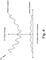
- FIG. 4 is graph 60 illustrating the correlation of the microstructure and planar porosity through the thickness of preform structure 50 before and after densification of a CMC component.
- Graph 60 includes axes labelled "XY Planar Porosity" and "Z-position within Composite". This type of profile can be created through processing micro xCT data obtained on preform structure 50 before and after densification.
- the vertical axis (XY Planar Porosity) is the planar porosity of preform structure 50.
- the horizontal axis (Z-position within Composite) is the vertical position within the thickness of preform structure 50, with the mid-plane of preform structure 50 being at the center position on graph 60 (i.e., between adjacent inner layers 52A).
- the Preform Gradient line represents preform structure 50 having a gradient microstructure ( FIG. 3 ) throughout the thickness of preform structure 50 before densification of preform structure 50. More specifically, the Preform Gradient line represents preform structure 50 having a lower planar average porosity (i.e., smaller average inter-tow pore size) at and near the mid-plane of preform structure 50 and higher planar average porosity (i.e., larger average inter-tow pore sizes) at and near exterior surface 58 of preform structure 50 (as shown in FIG. 3 ).
- a lower planar average porosity i.e., smaller average inter-tow pore size
- higher planar average porosity i.e., larger average inter-tow pore sizes
- the Dense Gradient line represents preform structure 50 with a gradient microstructure after densification of preform structure 50.
- a CMC component with the gradient microstructure has a uniform density throughout the thickness of the CMC component after densification. Therefore, preform structure 50 with a gradient microstructure before densification results in a uniform density through the thickness of CMC component after densification, and thus increases the mechanical and thermal properties of CMC component, as compared to a component formed from a preform structure with a uniform microstructure before densification.
- the gradient microstructure of preform structure 50 facilitates the uniform density after densification by having smaller pores 14 near the mid-plane (in some examples) of CMC components and larger pores 14 near exterior surface 58 of the component.
- the reactant vapors flow/travel through the network of porosity in preform structure 50 to create the matrix material.
- the larger pores 14 near exterior surface 58 allow the reactant vapors to easily travel through the network of pores 14 to the smaller pores 14 located near the mid-plane of preform structure 50.
- having smaller pores 14 near an exterior surface of a preform structure could result in densification at its exterior surface before the reactant vapors can reach the mid-plane of the preform structure, known as canning off.
- Canning off results in a high porosity/non-uniform density CMC components and reduced mechanical and thermal properties of the CMC component. It is highly desirable to have a low porosity/uniform density CMC component for gas turbine engine components.
- the low porosity/uniform density the CMC component provides improved interlaminar properties such as interlaminar tensile strength (ILT), interlaminar shear strength (ILS), and increases thermal conductivity of the CMC component.
- ILT interlaminar tensile strength
- ILS interlaminar shear strength
- CMC components formed from preform structures 50 having a gradient microstructure is advantageous because it results in an optimized pore structure and a more uniform densification of the CMC component, as compared to a CMC component with a uniform microstructure.
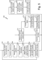
- FIG. 5 is a flow chart describing method 200 for preparing a ceramic fabric for use in a ceramic matrix composite.
- Method 200 includes steps 202, 204, 206, 208, 210, 212, 214, 216, 218, 220, 222, and 224.
- the sequence depicted by FIG. 5 is for illustrative purposes only and is not meant to limit method 200 in any way as it is understood that the portions of the method can proceed in a different logical order, additional or intervening portions can be included, or described portions of the method can be divided into multiple portions, or described portions of the method can be omitted without detracting from the described below.
- preform structure 50 begins by constructed one or more woven or braided ply layers using flattened (i.e., ribbonized) tows according to steps 202, 204, 206, 208, and 210.
- size material is removed from as-received tows 12 in preparation for the transformation process in step 204. While sizing material deposited on the exterior of tow 12 protects tow 12 while weaving or braiding tow 12 into ceramic fabric, it also helps tow 12 retain its shape. Removing the size material allows filaments of tow 12 to spread more easily and thereby allows formation of tow 18 to occur more readily. Desizing processes are tailored to particular sizing materials and tow materials.
- desizing can be achieved by heating tow 12, exposing tow 12 to a flame, or other oxidizing atmosphere, to burn off size material.
- Other processes include washing tow 12 in a heated fluid bath, such as water or ammonia, to break down or dissolve the sizing material.
- compression of tow 12 transforms tow 12 into tow 18 in step 204, flatting or reducing a dimension of tow 18 along a direction of compression and widening tow 18 along a direction orthogonal to the direction of compression.
- Methods of applying compression include attaching tow 12 in tension across two or more rollers, which may be arranged along axis 52 of tow 12. Drawing tow 12 through the rollers applies pressure to tow 12 in opposing directions. Similarly, tow 12 may be fed through a die. An aperture at an inlet end of the die approximates the as-received shape of tow 12.
- the aperture shape transitions to a flattened form such that drawing tow 12 through the die applies compression to opposite sides of tow 12 while allowing tow 12 to expand in a direction orthogonal to the compressive pressure.
- opposing jets of air or fluid impinge upon tow 12 to apply the compressive pressure.
- vacuum pressure can be used to draw tow 12 against a surface to produced transformed tow 18.
- step 204 produces tows 18 with reduced dimension along the direction of compressive pressure in proportion the applied pressure while increasing in dimension along a direction orthogonal to, and in proportion with, the applied compressive pressure.
- the dimension of tow 18 can be at little as 35% of the as-received dimension of tow 12.
- Orthogonal to the applied compressive pressure the dimension of tow 18 can be up to 250% of tow 12.
- the dimension reductions and corresponding orthogonal dimension increases of tow 18 relative to tow 12 are proportional to the applied compressive pressure.
- transformed tows 18 can be split into multiple subtows 22 prior to weaving or braiding ceramic fabric 16 in step 206.
- Methods for subtow creation include attaching tow 18 in tension across rollers equipped with spikes, ribs, or other protrusion or protrusions. As tow 18 passes over the roller, the protrusions impale tow 18 and thereby separate tow 18 into at least two subtows 22.
- Other methods for creating subtows 22 include drawing tow 18 through an air knife whereby an air jet impinges upon and separates tow 18 into two or more subtows 22. In some splitting operations, subtows 22 include 15% to 20% of the filaments from the parent tow. Splitting or separating tows 18 into subtows 22 may be used to further reduce or tailor the inter-tow pore size of ceramic fabric 16.
- tows 18 can be prepared in step 207 prior to weaving or braiding ceramic fabric 16.
- Preparing can refer to the wetting of tow 18 with water or ethanol.
- Tow preparation can include applying a thin layer of size material that protects filaments of tow 18 and reduces filament breakage as well as retains a flattened shape of tow 18 during subsequent weaving, braiding, and other processing steps.
- Sizing materials include polyvinyl alcohol (PVA) or poly-vinyl butyral (PVB), which can be applied by spraying tows 18 or bathing tows 18 with the size material.
- Weaving or braiding transformed tows 18, or subtows 22 produces ceramic fabric 16 in step 208.
- Weave patterns include harness satin, twill, and plain weaves while potential braid patterns include triaxial and biaxial braids. During the weaving or braiding process, tows 18 and/or subtows 22 remain untwisted.
- Weave patterns may have from 10 picks per inch (or ends per inch) to 16 picks per inch (or ends per inch) (3.9 to 6.3 picks/ends per cm), and braid patterns may have from 5 plaits per inch to 12 plaits per inch (2.0 to 4.7 plaits per cm).
- the degree to which tow 18 is flattened or transformed relative to tow 12 is selected to achieve a desired average inter-tow pore size for a given the weave or braid architecture.
- an average inter-tow pore size can range from 50 microns to 1500 microns. Expressed as a percentage of the center-to-center tow spacing, the average inter-tow pore size can be 55% or less of the center-to-center tow spacing of ceramic fabric 16. In other embodiments, the average inter-tow pore size is 35% or less of the average center-to-center tow spacing of the fabric 16. Planar porosity of ceramic fabric 16 can range from 0.2% to 90%.
- ceramic fabric 16 can be pre-impregnated with a plurality of ceramic particles.
- Suitable ceramic particles can be formed from silicon carbide, boron carbide, hafnium oxide, hafnium boride, aluminum oxide, ytterbium oxide, or zirconium boride, to name a few non-limiting examples.
- Ceramic particles can be a homogeneous or heterogenous mixture of generally spherical, elongate, or otherwise irregularly shaped particles (e.g. short ceramic fibers). In one embodiment, ceramic particles can range in size from 10 microns to 100 microns, depending on the size of tows used to construct the ceramic fabric, among other variables. In another embodiment, ceramic particles can range in size from 40 microns to 70 microns.
- one or more sheets 16 can be separated (e.g., cut or split) into plies.
- Steps 202, 204, 206, 208, and 210 can be repeated to create one or more additional ply layers.
- Additional ply layers can be constructed from tows 18 that have been transformed (i.e., flattened or ribbonized) to a greater or lesser degree than the initial ply layer to form a plurality of ply layers, each having a different average inter-tow pore size.
- Each ply layer of preform structure 50 can be constructed from transformed (i.e., flattened or ribbonized) tows in accordance with steps 202, 204, 206, 208, and 210.
- one or more of the ply layers can be constructed from as-received tows 12.
- as-received tows 12 are woven or braided to produce a ceramic fabric in step 212. Similar to step 208, weave patterns include harness satin, twill, and plain weaves while potential braid patterns include triaxial and biaxial braids.
- Weave patterns may have from 10 picks per inch (or ends per inch) to 16 picks per inch (or ends per inch) (3.9 to 6.3 picks/ends per cm) while braid patterns may have from 5 plaits to 12 plaits per inch (2.0 to 4.7 plaits per cm).
- ceramic fabric constructed from as-received tows is separated into one or more plies.
- Steps 216, 217, and 218 describe an alternative method of producing plies constructed with transformed tows.
- ceramic fabric constructed from as-received tows 12 can be produced in step 212.
- compressive pressure applied to the ceramic fabric transforms the woven or braided tows in step 216.
- Methods for applying pressure to the ceramic fabric include attaching the ceramic fabric in tension across rollers, two of which are arranged to apply opposing pressure to the fabric. As the ceramic fabric passes through the rollers, the as-received tows 12 within the ceramic fabric are flattened or ribbonized as described above.
- Other methods for applying compressive pressure to the ceramic fabric include opposing jets of air or fluid impinge upon the ceramic fabric to apply the compressive pressure.
- vacuum pressure can be used to draw ceramic fabric against a surface to produce a ceramic fabric constructed from transformed tows.
- transformed ceramic fabric can be pre-impregnated with a plurality of ceramic particles as described by step 209.
- the transformed ceramic fabric can be separated into one or more plies for constructed the preform structure.
- plies constructed from transformed tows 18 and, in some embodiments, plies constructed from as-received tows 12 are arranged into a desired two or three dimensional preform structure.
- Plies can be arranged to create a gradient of the average inter-tow pore size of the preform structures.
- plies with the smallest average inter-tow pore size form the most interior layers of preform structure 50.
- the average inter-tow pore size of adjacent ply layers increases towards the most exterior ply layers, which have the largest average inter-tow pore size.
- plies with the smallest average inter-tow pore size form the most exterior ply layers of preform structure 50.
- the average inter-tow pore size Adjacent to the exterior ply layer and proceeding inward, the average inter-tow pore size increases. In this instance, the most interior ply layer has the largest average inter-tow pore size. In other embodiments, some plies within the preform structure 50 maintain a constant average inter-tow pore size, with increasing or decreasing regions adjacent to plies defining a region of constant average inter-tow pore size.
- Step 220 can further optionally include deposition of particles onto preform structure 50.
- the volume fraction of particles added to the preform structure can be relatively low (e.g., 1% to 15%).
- Such particles may be formed from a ceramic material (e.g., silicon carbide, boron carbide, hafnium oxide, hafnium boride, aluminum oxide, ytterbium oxide, or zirconium boride) and are intended to remain as part of the structure through matrix formation and help enhance matrix formation and fortify the resultant CMC.
- the average particle size suitable for method 200 can be between 20 microns to 100 microns. In some embodiments, the particle size within a preform structure ranges from 40 microns to 70 microns with respect to the average particle size.
- the particles can alternatively be formed from a fugitive material designed to be later decomposed by thermal or chemical means.
- Fugitive particles can be formed from a polymer material such as polyvinyl alcohol (PVA), polyvinyl butyral (PVB), or polymethyl methacrylate (PMMA). Fugitive particles can help maintain spacing of pores 20 and tows 18 (or subtows 22) of sheet 16, as well as inter-ply spacing during subsequent processing steps.
- PVA polyvinyl alcohol
- PVB polyvinyl butyral
- PMMA polymethyl methacrylate
- the preform structure can undergo matrix formation and densification using a chemical vapor infiltration or deposition (CVI or CVD) process.
- CVI or CVD chemical vapor infiltration or deposition
- the plies are infiltrated by reactant vapors, and a gaseous precursor deposits on the fibers.
- the matrix material can be a silicon carbide or other suitable ceramic material. Densification is carried out until the resulting CMC has reached the desired residual porosity. Typically, one or several interphases are deposited prior to the matrix to ensure that the composite fails in a non-brittle manner.
- the diffusion rate of the inflitrant near exterior layers commonly outpaces the diffusion rate of the inflitrant rate of interior layers of the preform structure. This disparity of diffusion rate leads to increased matrix growth formation near exterior layers relative to matrix growth within interior layers. Accordingly, pores of exterior layers close prior to pores of interior layers, leading to voids within the component. Internal voids within a ceramic matrix composite (CMC) component can lead to decreased interlaminar properties.
- CMC ceramic matrix composite
- the average inter-tow pore size gradient increases from interior layers towards exterior layers.
- the disparity between the time of diffusion of the infiltrant to the most interior ply layers of the preform structure and the time of diffusion of the inflitrant to the most exterior layers is compensated by the inter-tow pore size gradient.
- the presence of voids within the preform structure is greatly reduced, leading to improved interlaminar tensile strength and interlaminar shear strength properties.
- reducing the presence of interior voids increases the density of the ceramic matrix composite (CMC) component.
- CMC ceramic matrix composite
- various post-processing steps can be performed, such as the application of one or more protective coatings (e.g., environmental and/or thermal barrier coatings).
- a bond coat can also be applied to facilitate bonding between the CMC and a protective coating.
- Other protective coatings especially those suitable for use in a gas turbine engine environment, are contemplated herein.
- a method of preparing a ceramic fabric for use in a ceramic matrix composite includes, among other possible steps, transforming a first ceramic tow from a first tow geometry to a second tow geometry, thereby reducing a first dimension of the first ceramic tow and increasing a second dimension of the first ceramic tow orthogonal to the first dimension to produce a first flattened ceramic tow.
- the method further includes weaving or braiding the first flattened tow to form a first ceramic fabric and weaving or braiding a second ceramic tow having the first tow geometry to form a second ceramic fabric.
- the method further includes separating the first ceramic fabric to form at least one first ply and separating the second ceramic fabric to form at least on second ply.
- the method includes laying up the first ply and the second ply to form a preform structure.
- the method of the preceding paragraph can optionally include, additionally and/or alternatively, any one or more of the following features, configurations, additional components, and/or steps.
- first ceramic fabric can include silicon carbide tows.
- the second ceramic fabric can include silicon carbide tows.
- a further embodiment of any of the foregoing methods can include transforming a third ceramic tow from the first tow geometry to a third tow geometry, thereby reducing a third dimension of the third ceramic tow and increasing a fourth dimension of the third ceramic tow orthogonal to the third dimension to produce a second flattened ceramic tow.
- a further embodiment of any of the foregoing methods can include weaving or braiding the second flattened ceramic tow to form a third ceramic fabric.
- a further embodiment of any of the foregoing methods can include separating the third ceramic fabric into at least on third ply.
- a further embodiment of any of the foregoing methods can include laying up the first ply, the second ply, and the third ply to form the preform structure.
- transforming the first ceramic tow to the second tow geometry and transforming the third ceramic tow to the third tow geometry includes applying a first pressure to opposite sides of the first ceramic tow and applying a second pressure to the third ceramic tow.
- a further embodiment of any of the foregoing methods wherein a first average inter-tow pore size of the first ply is less than a second average inter-tow pore size of the second ply.
- first average inter-tow pore size of the first ply can be less than the second average inter-tow pore size of the second ply.
- a further embodiment of any of the foregoing methods can include densifying the preform structure using a chemical vapor infiltration process.
- Another method of preparing a ceramic fabric for use in a ceramic matrix composite includes, among other possible steps, weaving or braiding a plurality of first ceramic tows to form a first ceramic fabric, an average first inter-tow pore size that is between 30% and 55% of an average center-to-center spacing of the first ceramic tows.
- the method includes weaving or braiding a plurality of second ceramic tows to form a second ceramic fabric, an average second inter-tow pore size that is between 30% and 55% of an average center-to-center spacing of the second ceramic tows.
- the method includes transforming the first ceramic fabric from the first average inter-tow pore size to a third average inter-tow pore size by applying a first pressure to opposite sides of the first ceramic fabric.
- the third average inter-tow pore size is less than 30% of the average center-to-center spacing of the first ceramic tows.
- the method includes separating the first ceramic fabric into at least one first ply after transforming the first ceramic fabric and separating the second ceramic fabric into at least one second ply.
- the method includes laying up the first ply and the second ply to form a preform structure.
- the method of the preceding paragraph can optionally include, additionally and/or alternatively, any one or more of the following features, configurations, additional components, and/or steps.
- the first ceramic fabric comprises silicon carbide tows.
- a further embodiment of any of the foregoing methods can include weaving or braiding a plurality of third ceramic tows to form a third ceramic fabric, an average fourth inter-tow pore size that is between 30% and 55% of an average center-to-center spacing of the third ceramic tows.
- a further embodiment of any of the foregoing methods can include transforming the third ceramic fabric from the fourth average inter-tow pore size to a fifth average inter-tow pore size by applying a second pressure to opposite sides of the third ceramic fabric different than the first pressure.
- a further embodiment of any of the foregoing methods can include laying up the first ply, the second ply, and the third ply to form the preform structure.
- a further embodiment of any of the foregoing methods, wherein the third average inter-tow pore size and the fifth average inter-tow pore size can be at least 50 microns, respectively.
- a further embodiment of any of the foregoing methods can include densifying the preform structure using a chemical vapor infiltration process.
- a ceramic preform is provided as set forth in claim 11.
- a ceramic matrix composite component is provided as set forth in claim 15.
Landscapes
- Engineering & Computer Science (AREA)
- Chemical & Material Sciences (AREA)
- Textile Engineering (AREA)
- Ceramic Engineering (AREA)
- Manufacturing & Machinery (AREA)
- Structural Engineering (AREA)
- Materials Engineering (AREA)
- Organic Chemistry (AREA)
- Chemical Kinetics & Catalysis (AREA)
- Inorganic Chemistry (AREA)
- Woven Fabrics (AREA)
- Porous Artificial Stone Or Porous Ceramic Products (AREA)
- Ceramic Products (AREA)
Applications Claiming Priority (1)
| Application Number | Priority Date | Filing Date | Title |
|---|---|---|---|
| US17/645,194 US12312724B2 (en) | 2021-12-20 | 2021-12-20 | Gradient tow ribbonizing for chemical vapor infiltration ceramic matrix composites |
Publications (2)
| Publication Number | Publication Date |
|---|---|
| EP4197782A2 true EP4197782A2 (fr) | 2023-06-21 |
| EP4197782A3 EP4197782A3 (fr) | 2023-11-01 |
Family
ID=84487490
Family Applications (1)
| Application Number | Title | Priority Date | Filing Date |
|---|---|---|---|
| EP22212614.6A Pending EP4197782A3 (fr) | 2021-12-20 | 2022-12-09 | Rubanisation par câble à gradient pour l'intelligence chimique en phase vapeur de composites à matrice céramique |
Country Status (2)
| Country | Link |
|---|---|
| US (1) | US12312724B2 (fr) |
| EP (1) | EP4197782A3 (fr) |
Families Citing this family (3)
| Publication number | Priority date | Publication date | Assignee | Title |
|---|---|---|---|---|
| US12099894B2 (en) * | 2019-09-20 | 2024-09-24 | Rtx Corporation | Composite material marking and identification |
| US20250026690A1 (en) * | 2023-07-21 | 2025-01-23 | Rohr, Inc. | Porosity gradient preform architecture for high temperature composites |
| US20250026103A1 (en) * | 2023-07-21 | 2025-01-23 | Rohr, Inc. | Porosity gradient preform architecture for high temperature composites |
Family Cites Families (48)
| Publication number | Priority date | Publication date | Assignee | Title |
|---|---|---|---|---|
| JPS6440663A (en) | 1987-08-03 | 1989-02-10 | Mitsubishi Rayon Co | Method for correcting mesh size of fabric |
| US5049329A (en) | 1989-10-30 | 1991-09-17 | Corning Incorporated | Process for forming ceramic matrix composites |
| DE4102909A1 (de) | 1991-01-31 | 1992-08-06 | Man Technologie Gmbh | Werkstuecke aus faserverstaerkter keramik |
| US5250243A (en) | 1991-12-02 | 1993-10-05 | Corning Incorporated | Method for making ceramic matrix composites |
| JP2955145B2 (ja) | 1992-09-08 | 1999-10-04 | 東レ株式会社 | 扁平糸織物とその製造方法および製造装置 |
| EP0623571A4 (fr) | 1992-11-26 | 1997-07-02 | Tonen Corp | Procede pour fabriquer des produits en ceramique. |
| FR2698640B1 (fr) | 1992-11-30 | 1995-02-17 | Brochier Sa | Tissu chaîne et trame à base de fils techniques multifilaments à prédominance sans torsion et procédé d'obtention. |
| US5547622A (en) | 1995-03-15 | 1996-08-20 | Corning Incorporated | Binder for fiber reinforced composites |
| US5756206A (en) | 1995-03-15 | 1998-05-26 | Custom Composite Materials, Inc. | Flexible low bulk pre-impregnated tow |
| US6641893B1 (en) | 1997-03-14 | 2003-11-04 | Massachusetts Institute Of Technology | Functionally-graded materials and the engineering of tribological resistance at surfaces |
| FR2761380B1 (fr) | 1997-03-28 | 1999-07-02 | Europ Propulsion | Procede et machine pour la realisation de nappes fibreuses multiaxiales |
| JP2983531B1 (ja) | 1998-09-29 | 1999-11-29 | 福井県 | 開繊糸織物の製造方法とその装置 |
| JP4647053B2 (ja) | 1999-02-09 | 2011-03-09 | 日本碍子株式会社 | SiC−C/Cコンポジット複合材料、その用途、およびその製造方法 |
| US7413694B2 (en) | 1999-12-07 | 2008-08-19 | The Boeing Company | Double bag vacuum infusion process |
| US6627019B2 (en) | 2000-12-18 | 2003-09-30 | David C. Jarmon | Process for making ceramic matrix composite parts with cooling channels |
| GB0401645D0 (en) | 2004-01-26 | 2004-02-25 | Cytec Tech Corp | Stabilizable preform precursors and stabilized preforms for composite materials and processes for stabilizing and debulking preforms |
| JP4837897B2 (ja) | 2004-03-31 | 2011-12-14 | サカイオーベックス株式会社 | 繊維強化樹脂およびその製造方法 |
| US20070096371A1 (en) | 2005-10-27 | 2007-05-03 | General Electric Company | Process of producing ceramic matrix composites |
| US20070099527A1 (en) | 2005-11-01 | 2007-05-03 | General Electric Company | Method and reactor to coat fiber tows and article |
| JP4797820B2 (ja) | 2006-06-14 | 2011-10-19 | 株式会社豊田自動織機 | 配列ヘッド |
| US20100119777A1 (en) | 2006-11-16 | 2010-05-13 | Siemens Power Generation, Inc. | Ceramic matrix composite surfaces with open features for improved bonding to coatings |
| US7837914B2 (en) | 2006-12-04 | 2010-11-23 | General Electric Company | Process of producing a composite component and intermediate product thereof |
| FR2939130B1 (fr) | 2008-11-28 | 2011-09-16 | Snecma Propulsion Solide | Procede de fabrication de piece de forme de forme complexe en materiau composite. |
| US20120074265A1 (en) | 2009-06-11 | 2012-03-29 | Saab Ab | Nano-reinforced radius filler for an aircraft structure and a method of producing an aircraft structure comprising such filler |
| FR2952052B1 (fr) | 2009-10-30 | 2012-06-01 | Snecma Propulsion Solide | Piece en materiau composite thermostructural de faible epaisseur et procede de fabrication. |
| FR2954356B1 (fr) | 2009-12-22 | 2012-01-13 | Hexcel Reinforcements | Nouveaux materiaux intermediaires realises par entrecroisement avec entrelacement de fils voiles |
| US8440045B2 (en) | 2011-09-14 | 2013-05-14 | Sikorsky Aircraft Corporation | Conformal deltoid noodle for a composite structure |
| US8545938B2 (en) | 2011-10-03 | 2013-10-01 | United Technologies Corporation | Method of fabricating a ceramic component |
| US20140099484A1 (en) | 2012-10-04 | 2014-04-10 | General Electric Company | Ceramic matrix composite, method of making a ceramic matrix composite, and a pre-preg composite ply |
| WO2014151066A1 (fr) | 2013-03-15 | 2014-09-25 | Chamberlain Adam L | Optimisation d'une architecture à fibres pour composites à matrice en céramique |
| RU2016134446A (ru) | 2014-02-25 | 2018-03-29 | Сименс Акциенгезелльшафт | Термобарьерное покрытие компонента турбины с изменяющимися по глубине свойствами материала |
| US11072565B2 (en) | 2015-02-27 | 2021-07-27 | General Electric Company | Ceramic matrix composite structures with controlled microstructures fabricated using chemical vapor infiltration (CVI) |
| DE102015209535A1 (de) | 2015-05-22 | 2016-11-24 | Bayerische Motoren Werke Aktiengesellschaft | Verfahren und Vorrichtung zur Herstellung eines Faserhalbzeugs, Faserhalbzeug und Verfahren zur Herstellung eines faserverstärkten Kunststoffbauteils |
| FR3041890B1 (fr) | 2015-10-05 | 2017-11-24 | Snecma | Procede de fabrication d'une piece en materiau composite par injection d'une barbotine chargee dans un moule poreux |
| FR3042188B1 (fr) | 2015-10-08 | 2017-11-24 | Snecma | Procede de fabrication d'un assemblage fibreux impregne |
| US20170348876A1 (en) | 2016-05-31 | 2017-12-07 | General Electric Company | Thin ply high temperature composites |
| US10829418B2 (en) | 2017-11-27 | 2020-11-10 | United Technologies Corporation | Method of densifying a ceramic matrix composite using a filled tackifier |
| US11117838B2 (en) | 2018-05-23 | 2021-09-14 | Rolls-Royce High Temperature Composites Inc. | Method of making a fiber preform for ceramic matrix composite (CMC) fabrication |
| US11524480B2 (en) | 2018-06-22 | 2022-12-13 | Rolls-Royce Corporation | Adaptive microtexturing of a composite material |
| US11015467B2 (en) | 2018-07-06 | 2021-05-25 | Raytheon Technologies Corporation | Porous space fillers for ceramic matrix composites |
| US20200078822A1 (en) | 2018-09-07 | 2020-03-12 | University Of Louisiana At Lafayette | Method for Automated Spraying of Nanoparticles |
| US10822281B2 (en) | 2018-11-09 | 2020-11-03 | Raytheon Technologies Corporation | Accelerated CVI densification of CMC through infiltration |
| US20200385898A1 (en) | 2019-06-10 | 2020-12-10 | Corex Materials Corporation | Fabrics woven by spread tow yarns consisting of polymer matrix composite and method for producing the same |
| EP3996889B1 (fr) | 2019-07-11 | 2024-01-10 | Safran Aircraft Engines | Procede de fabrication d'une piece en materiau composite par injection d'une barbotine chargee dans une texture fibreuse |
| CN111058187B (zh) | 2019-12-27 | 2021-03-19 | 中南大学 | 一种附着界面层的SiC纤维预浸带的制备方法及设备 |
| US11624287B2 (en) | 2020-02-21 | 2023-04-11 | Raytheon Technologies Corporation | Ceramic matrix composite component having low density core and method of making |
| US20230019485A1 (en) | 2021-07-14 | 2023-01-19 | Raytheon Technologies Corporation | Homogeneous composite microstructure |
| US12017379B2 (en) * | 2021-12-20 | 2024-06-25 | Rtx Corporation | Ribbonized tows for optimized improved composite performance |
-
2021
- 2021-12-20 US US17/645,194 patent/US12312724B2/en active Active
-
2022
- 2022-12-09 EP EP22212614.6A patent/EP4197782A3/fr active Pending
Also Published As
| Publication number | Publication date |
|---|---|
| EP4197782A3 (fr) | 2023-11-01 |
| US12312724B2 (en) | 2025-05-27 |
| US20230193541A1 (en) | 2023-06-22 |
Similar Documents
| Publication | Publication Date | Title |
|---|---|---|
| EP4197782A2 (fr) | Rubanisation par câble à gradient pour l'intelligence chimique en phase vapeur de composites à matrice céramique | |
| US20260034707A1 (en) | Ribbonized tows for optimized improved composite performance | |
| CN102782256B (zh) | 采用复合材料制成的涡轮发动机叶片和制造该叶片的方法 | |
| CN102712546B (zh) | 低厚度热结构复合材料部件和制造方法 | |
| US20230192561A1 (en) | Controlled gradient of porosity in cmc | |
| JP6318175B2 (ja) | 湾曲したセラミック音響減衰パネルの製造方法 | |
| CN112543749A (zh) | 由cmc制成的零件的制造方法 | |
| EP4119709B1 (fr) | Microstructure composite homogène | |
| US20180362413A1 (en) | Methods of Forming Ceramic Matrix Composites Using Sacrificial Fibers and Related Products | |
| RU2566696C2 (ru) | Способ изготовления массивной детали | |
| CN102232019A (zh) | 用于制造复杂形状的复合材料部件的方法 | |
| US20110121109A1 (en) | Method of producing a nozzle or a divergent nozzle element made of a composite | |
| KR20090024263A (ko) | 복합물 부재용 다중-사틴 위브의 섬유 보강 구조물 | |
| EP4197781A1 (fr) | Stabilisation sous pression de couches pour des propriétés interlaminaires améliorées | |
| US20180194686A1 (en) | A method of treating silicon carbide fibers | |
| CN105593417A (zh) | 具有分组浮丝的纤维结构 | |
| JPH0586534A (ja) | 複合材料製品製造のための耐火性繊維製プレフオームの製造方法 | |
| CN111302820B (zh) | 一种C/SiC复合材料的制备方法 | |
| EP1566370A2 (fr) | Nappes pour améliorer les propriétés thermo-mécaniques pour des stratifiés de composites CVI/SiC à matrice céramique. | |
| EP4144524A1 (fr) | Dimensionnement de filament de polymère super-absorbant pour des applications cmc | |
| EP4431483A1 (fr) | Armure tridimensionnelle avec fibres z sacrificielles pour microstructure composite à matrice céramique améliorée | |
| EP4477413A1 (fr) | Composite à matrice céramique améliorée par particules sans particules sur des couches de surface | |
| US20250128453A1 (en) | Pre-shaped space fillers for small cross section features | |
| EP3689841A1 (fr) | Procédé de fabrication d'une fibre de carbone résistante à l'oxydation |
Legal Events
| Date | Code | Title | Description |
|---|---|---|---|
| PUAI | Public reference made under article 153(3) epc to a published international application that has entered the european phase |
Free format text: ORIGINAL CODE: 0009012 |
|
| STAA | Information on the status of an ep patent application or granted ep patent |
Free format text: STATUS: THE APPLICATION HAS BEEN PUBLISHED |
|
| AK | Designated contracting states |
Kind code of ref document: A2 Designated state(s): AL AT BE BG CH CY CZ DE DK EE ES FI FR GB GR HR HU IE IS IT LI LT LU LV MC ME MK MT NL NO PL PT RO RS SE SI SK SM TR |
|
| RIC1 | Information provided on ipc code assigned before grant |
Ipc: D04C 1/02 20060101ALI20230626BHEP Ipc: D03D 15/46 20210101ALI20230626BHEP Ipc: D02J 1/18 20060101ALI20230626BHEP Ipc: C04B 35/80 20060101ALI20230626BHEP Ipc: B32B 18/00 20060101AFI20230626BHEP |
|
| PUAL | Search report despatched |
Free format text: ORIGINAL CODE: 0009013 |
|
| AK | Designated contracting states |
Kind code of ref document: A3 Designated state(s): AL AT BE BG CH CY CZ DE DK EE ES FI FR GB GR HR HU IE IS IT LI LT LU LV MC ME MK MT NL NO PL PT RO RS SE SI SK SM TR |
|
| RAP3 | Party data changed (applicant data changed or rights of an application transferred) |
Owner name: RTX CORPORATION |
|
| RIC1 | Information provided on ipc code assigned before grant |
Ipc: D04C 1/02 20060101ALI20230926BHEP Ipc: D03D 15/46 20210101ALI20230926BHEP Ipc: D02J 1/18 20060101ALI20230926BHEP Ipc: C04B 35/80 20060101ALI20230926BHEP Ipc: B32B 18/00 20060101AFI20230926BHEP |
|
| STAA | Information on the status of an ep patent application or granted ep patent |
Free format text: STATUS: REQUEST FOR EXAMINATION WAS MADE |
|
| 17P | Request for examination filed |
Effective date: 20240501 |
|
| RBV | Designated contracting states (corrected) |
Designated state(s): AL AT BE BG CH CY CZ DE DK EE ES FI FR GB GR HR HU IE IS IT LI LT LU LV MC ME MK MT NL NO PL PT RO RS SE SI SK SM TR |