EP4197786B1 - Verfahren und system für selbstwartung und rueckgewinnungssystem für einen druckkopf - Google Patents
Verfahren und system für selbstwartung und rueckgewinnungssystem für einen druckkopf Download PDFInfo
- Publication number
- EP4197786B1 EP4197786B1 EP21215072.6A EP21215072A EP4197786B1 EP 4197786 B1 EP4197786 B1 EP 4197786B1 EP 21215072 A EP21215072 A EP 21215072A EP 4197786 B1 EP4197786 B1 EP 4197786B1
- Authority
- EP
- European Patent Office
- Prior art keywords
- conduit
- opening
- printhead
- removal unit
- material removal
- Prior art date
- Legal status (The legal status is an assumption and is not a legal conclusion. Google has not performed a legal analysis and makes no representation as to the accuracy of the status listed.)
- Active
Links
Images


Classifications
-
- B—PERFORMING OPERATIONS; TRANSPORTING
- B41—PRINTING; LINING MACHINES; TYPEWRITERS; STAMPS
- B41J—TYPEWRITERS; SELECTIVE PRINTING MECHANISMS, i.e. MECHANISMS PRINTING OTHERWISE THAN FROM A FORME; CORRECTION OF TYPOGRAPHICAL ERRORS
- B41J2/00—Typewriters or selective printing mechanisms characterised by the printing or marking process for which they are designed
- B41J2/005—Typewriters or selective printing mechanisms characterised by the printing or marking process for which they are designed characterised by bringing liquid or particles selectively into contact with a printing material
- B41J2/01—Ink jet
- B41J2/135—Nozzles
- B41J2/14—Structure thereof only for on-demand ink jet heads
- B41J2/1433—Structure of nozzle plates
-
- B—PERFORMING OPERATIONS; TRANSPORTING
- B05—SPRAYING OR ATOMISING IN GENERAL; APPLYING FLUENT MATERIALS TO SURFACES, IN GENERAL
- B05B—SPRAYING APPARATUS; ATOMISING APPARATUS; NOZZLES
- B05B15/00—Details of spraying plant or spraying apparatus not otherwise provided for; Accessories
- B05B15/50—Arrangements for cleaning; Arrangements for preventing deposits, drying-out or blockage; Arrangements for detecting improper discharge caused by the presence of foreign matter
- B05B15/52—Arrangements for cleaning; Arrangements for preventing deposits, drying-out or blockage; Arrangements for detecting improper discharge caused by the presence of foreign matter for removal of clogging particles
-
- B—PERFORMING OPERATIONS; TRANSPORTING
- B41—PRINTING; LINING MACHINES; TYPEWRITERS; STAMPS
- B41J—TYPEWRITERS; SELECTIVE PRINTING MECHANISMS, i.e. MECHANISMS PRINTING OTHERWISE THAN FROM A FORME; CORRECTION OF TYPOGRAPHICAL ERRORS
- B41J2/00—Typewriters or selective printing mechanisms characterised by the printing or marking process for which they are designed
- B41J2/005—Typewriters or selective printing mechanisms characterised by the printing or marking process for which they are designed characterised by bringing liquid or particles selectively into contact with a printing material
- B41J2/01—Ink jet
- B41J2/135—Nozzles
- B41J2/16—Production of nozzles
- B41J2/1606—Coating the nozzle area or the ink chamber
-
- B—PERFORMING OPERATIONS; TRANSPORTING
- B41—PRINTING; LINING MACHINES; TYPEWRITERS; STAMPS
- B41J—TYPEWRITERS; SELECTIVE PRINTING MECHANISMS, i.e. MECHANISMS PRINTING OTHERWISE THAN FROM A FORME; CORRECTION OF TYPOGRAPHICAL ERRORS
- B41J2/00—Typewriters or selective printing mechanisms characterised by the printing or marking process for which they are designed
- B41J2/005—Typewriters or selective printing mechanisms characterised by the printing or marking process for which they are designed characterised by bringing liquid or particles selectively into contact with a printing material
- B41J2/01—Ink jet
- B41J2/135—Nozzles
- B41J2/165—Prevention or detection of nozzle clogging, e.g. cleaning, capping or moistening for nozzles
- B41J2/16502—Printhead constructions to prevent nozzle clogging or facilitate nozzle cleaning
-
- B—PERFORMING OPERATIONS; TRANSPORTING
- B41—PRINTING; LINING MACHINES; TYPEWRITERS; STAMPS
- B41J—TYPEWRITERS; SELECTIVE PRINTING MECHANISMS, i.e. MECHANISMS PRINTING OTHERWISE THAN FROM A FORME; CORRECTION OF TYPOGRAPHICAL ERRORS
- B41J2/00—Typewriters or selective printing mechanisms characterised by the printing or marking process for which they are designed
- B41J2/005—Typewriters or selective printing mechanisms characterised by the printing or marking process for which they are designed characterised by bringing liquid or particles selectively into contact with a printing material
- B41J2/01—Ink jet
- B41J2/135—Nozzles
- B41J2/165—Prevention or detection of nozzle clogging, e.g. cleaning, capping or moistening for nozzles
- B41J2/16517—Cleaning of print head nozzles
- B41J2/1652—Cleaning of print head nozzles by driving a fluid through the nozzles to the outside thereof, e.g. by applying pressure to the inside or vacuum at the outside of the print head
- B41J2/16532—Cleaning of print head nozzles by driving a fluid through the nozzles to the outside thereof, e.g. by applying pressure to the inside or vacuum at the outside of the print head by applying vacuum only
-
- B—PERFORMING OPERATIONS; TRANSPORTING
- B41—PRINTING; LINING MACHINES; TYPEWRITERS; STAMPS
- B41J—TYPEWRITERS; SELECTIVE PRINTING MECHANISMS, i.e. MECHANISMS PRINTING OTHERWISE THAN FROM A FORME; CORRECTION OF TYPOGRAPHICAL ERRORS
- B41J2/00—Typewriters or selective printing mechanisms characterised by the printing or marking process for which they are designed
- B41J2/005—Typewriters or selective printing mechanisms characterised by the printing or marking process for which they are designed characterised by bringing liquid or particles selectively into contact with a printing material
- B41J2/01—Ink jet
- B41J2/17—Ink jet characterised by ink handling
- B41J2/18—Ink recirculation systems
- B41J2/185—Ink-collectors; Ink-catchers
Definitions
- the invention relates to a method and system for a self-maintenance and recovery system for a printhead.
- the invention relates to method and system for a material removal unit and or material recovery unit for a printhead, preferably for an inkjet-type printhead, preferably for a 3D-printhead.
- printhead Such a printhead is described e.g. in EP 3 825 100 A1 .
- the method and system of the present invention is also suitable for any other printhead for liquid material droplets.
- US 2011/017841 A1 relates to a method and a system for jetting droplets of viscous medium, such as solder paste, onto a substrate, such as an electronic circuit board.
- US 2018/272364 A1 relates to a nozzle capable of removing a surplus liquid material, which is adhered to outer surfaces of the nozzle and which affects a discharge operation, without undergoing a special process, and a liquid material discharge device provided with the nozzle.
- US 2011/199432 A1 relates to a nozzle guard with a suction flow path in which a suction port is opened to a lower portion of nozzles, and is communicated to an inside space of the nozzle guard, in which the inside space of the nozzle guard is rendered a negative pressure chamber by a suction portion connected to the suction flow path, and a first liquid overflowing the nozzles to the negative pressure chamber is sucked.
- a material ejection orifice ejects a material droplet by an actuation of an actuating member, imparting a physical impulse onto the liquid material present in the printing head.
- Said liquid material is forming a meniscus, or in other words, is forming a liquid gas interface at a position controlled by a negative internal pressure. This results in a difference in pressure between the outside of the nozzle containing element and the inside of said nozzle containing element, i.e. a liquid material reservoir.
- the meniscus is formed in a position for ideal ejection under normal operation of said printhead. Said meniscus has the potential to protrude in a direction away from the nozzle opening until the gas liquid interface is no longer connected to the nozzle opening and causes a wetting of the surrounding surface around the nozzle opening. This is leading to a pendant drop formation of excess material.
- This excess material is impeding the controlled release of further droplets from the ejection orifice, due to an interference of the ejected material and the excess material via surface tension and/or non-uniform kinetic energy transfer, which is degrading the printing performance.
- It is a core aspect of the present invention to provide material removal unit comprising at least one conduit forming element configured to remove excess material from at least one ejection orifice.
- the conduit forming element is provided on or close to a connecting nozzle containing element of a printhead.
- a pressure gradient and/or a drag force are affecting the excess liquid material present in an affected area around said orifice, thereby the excess material is removed, and desired ejection performance is obtained.
- the material removal unit is connected to a reservoir and thus forms a material recovery unit.
- the problem of removing excess material, while not negatively affecting the ejection of large droplets form the ejection orifice is addressed.
- This is solved by allowing a large enough distance from the flight path of ejected droplets to the through opening of the conduit forming element. Thereby direct contact of said larger droplets with the conduit forming element is prevented, while still retaining a high efficiency in removing excess material from the nozzle well.
- the problem of ensuring that the position of an excess amount of material beyond a threshold, at which it can negatively affect the drop ejection performance is addressed.
- the excess material is transported to a position such that it is not contacting material being ejected from the ejection orifice.
- the transport is based on the material surface tension and is positioning the material closer to a conduit opening.
- the dragging force is increased, which allows for a more effective transport of the excess material to the conduit opening.
- the problem of removing an excess material present in the nozzle well is addressed.
- Excess material present in the nozzle well can result in the release unwanted droplets, thereby negatively impacting printing performance.
- Excess material present in the nozzle well is neither connected or affected by a surface tension interaction with the ejection orifice or the conduit opening. This is in a first sub-embodiment resolved by utilizing a dragging force emanating from a negative pressure conduit opening which is sucking in ambient gas, whereby said gas introduces a dragging force on the surface of such an excess material, thereby ideally moving it towards the negative pressure conduit opening.
- the transport may be based on the use of a remnant vibrational energy originating from the actuator of the printhead or on pressure fluctuations induced by the dragging force. Said vibrations deforming the droplet and causing it to anchor on half rounded structures of differential surface energy areas present on the underside of the nozzle containing element via the use of anti-stiction coatings and non-coated areas. This causes a ratchet conveyor type displacement of the droplet by favoring a direction of motion caused by the geometry of said half rounded structures. Said motion being directed towards the conduit openings and/or generally being directed along the pressure gradient them present in the conduits.
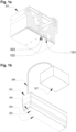
- Fig. 1a shows a sectional perspective drawing of printhead according to an embodiment of the invention.
- Fig. 1b shows a perspective drawing of printhead according an embodiment of the invention.
- the printhead 301 of Fig. 1a comprises a nozzle plate with a plurality of ejection orifices 303.
- a material removal unit, MRU, according to the invention comprises at least one pass-through opening 103 respectively arranged in correspondence with the at least one ejection orifices 303.
- the printhead may have a stacked architecture, i.e. it comprises a plurality of functional units stacked upon each other.
- the MRU is preferably located below the nozzle plate in a direction of the droplet ejection.
- the MRU is also be provided in form of a plate in the stacked architecture.
- the printhead 301 as shown in Fig. 1b comprises a vacuum connector 306; a nozzle containing element 302, also referred to as nozzle plate, situated above the conduit forming element 101 of the MRU.
- the conduit forming element 101 is fastened to said nozzle containing element 302 and sealing said conduit forming channels 102 in order to create conduits 201, see Fig. 4a to 4c .
- Fig. 2a shows a nozzle plate 302 of a 3D printhead according to an embodiment of the present invention.
- Fig. 2b shows a conduit forming element of a material removal unit according to an embodiment of the present invention.
- the nozzle plate 302 corresponds to the nozzle plate in Fig. 1b .
- the elements of the MRU in Fig. 2b positionally correspond to the elements of the nozzle plate 302 in Fig. 2a .
- the material removal unit comprises: a conduit forming element 101 with at least one conduit forming channel 102, preferably forming a low-pressure material conduit.
- the conduit forming channel 102 is connecting at least one pass-through opening 103 and at least one low pressure connecting point 104.
- the MRU further preferably comprises at least one conduit opening 105 formed near said pass-through opening 103.
- the nozzle containing element 302 has at least one ejection orifice or nozzle 303, arranged in correspondence to said pass-through opening 103.
- the diameter of said ejection orifice 303 is preferably smaller than the diameter of the corresponding pass through opening 103, so that a droplet ejected from said nozzle is not affected by the pass-through opening.
- the area of the nozzle containing element 302 situated above the conduit forming element 101 and being positioned within the area of the pass-through opening 103 is also referred to as a nozzle well 106, see Fig. 3 .
- the conduit forming element 101 is configured to be fastened to the nozzle containing element 302.
- the fastening between the nozzle containing element 302 and the conduit forming element 101 is sealed.
- the conduits 201 preferably low-pressure material conduits, are formed, see Figs. 4a to 4c .
- the invention is neither limited to closed conduits nor to the fastening on a nozzle containing element.
- At least one separate cover element may be provided, which is configured to close the at least one conduit 201 at least one side thereof.
- the cover element may be provided on top and/or below the conduit forming element and thus close the top and/or bottom of the formed conduits 201.
- the conduits 201 are open at one side, preferably the bottom side (in the droplet ejection direction).
- the conduits 201 are still suitable for transport of a liquid material due to capillary effects and/or surface tension.
- the conduit 201 is connected to the low-pressure connecting point 104.
- the low-pressure connecting point 104 is configured to remove gas and liquid material 401 present within the conduit 201, preferably via a pressure gradient.
- the pressure gradient is formed such that the gas and material is moved away from said conduit, preferably the conduit opening 105.
- a vacuum pump is connected to the connection point 104.
- the vacuum pump is connected to a vacuum connector 306 in the nozzle plate, i.e. connected to the low-pressure connecting point 104.
- the use of a vacuum pump allows for the transport of liquid material.
- the liquid material is transported via the vacuum tube 308 to the liquid material reservoir 307.
- the material reservoir is part of the printhead.
- the material removed by the MRU is transported, i.e. recycled, to the printhead and thus a material recovery unit is formed.
- vacuum is used in this description not only in its strict scientific meaning, but also in a broader more common technical meaning of a low-pressure or underpressurized condition.
- said liquid material reservoir 307 is configured to further transport the removed material to a waste container. Additionally or alternatively said reservoir is configured to further transport said material to a material cycling system, preferably located in the printhead.
- Fig. 3 shows the bottom surface of the conduit forming element 101 according to an embodiment of the invention. That is, the opposite surface as shown in Fig. 2b . Only the pass-through opening 103 and the nozzle well 106 within said opening are visible.
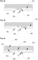
- Fig. 4a shows the material removal unit according to an embodiment of the invention in a state after drop ejection and a pendant droplet of excess material being formed.
- Fig. 4b shows the material removal unit according to an embodiment of the invention in a state after drop ejection with material being removed.
- Fig. 4c shows the material removal unit according to an embodiment of the invention in a state after drop ejection after material removal.
- Figs. 4a to 4c illustrate the material removal process according to an embodiment of the invention.
- the continuous restoration of material ejection properties in this case is performed by a removal of the excess material via the nozzle well 106.
- the geometry of the nozzle well 106 is utilized in order to allow for a path for a droplet 401 in excess of a certain size, i.e. threshold, to be guided to the conduit opening 105.
- a certain size i.e. threshold
- the droplet connects to or is attracted by the low-pressure conduit 201.
- the conduit 201 is configured to suck in atmospheric gas via a negative pressure and said gas exhibiting a dragging force on the excess material 401 present in the nozzle well 106, thereby forcing it towards the conduit opening, cf. Fig. 4b .
- the liquid printing material 401 may be ejected trough ejection orifice 303.
- the material may form pendent-drops upon ejection.
- the formation of a droplet may lead to excess material 401 forming in an area around the ejection orifice 303.
- the excess material reaches the first end of the conduit 201, it is transported into the conduit and subsequently transported in the conduit in a direction away from the first end towards the second end.
- the material ejection orifice is located at the center of the pass-through opening, allowing for uninhibited passage of intentionally ejected material, facilitated by the actuation of an actuating member by imparting a physical impulse onto the liquid material present in the printing head.
- Said liquid material is forming a meniscus, or in other words, it is forming a liquid-gas interface at a position controlled by a negative internal pressure.
- the meniscus is formed in a position for ideal ejection under normal operation of said printhead.
- Said meniscus has the potential to protrude downward until the gas liquid interface is no longer connected to the nozzle opening and causes a wetting of a surrounding surface around the nozzle, leading to a pendant drop formation of excess material.
- This excess material is impeding the controlled release of droplets from the ejection orifice opening due to an interference of the ejected material and the excess material via surface tension and/or non-uniform kinetic energy transfer; thereby degrading printing performance.
- a pendant drop of excess material can be formed in the area next to the nozzle and inside the nozzle well.
- the movement of the gas in the conduit 201 is caused by least one or more conduit openings 105 being connected to the vacuum pump, thereby creating a directional drag force across the entire nozzle well 106.
- the pass through opening 103 can be large, in relation to a size at which capillary forces are relevant, and the ejection of large and small droplets from the same ejection orifice 303 becomes possible, without an ejected droplet touching the conduit forming element at the walls of the pass through opening.
- the droplet volume of ejected material may range from 1pl to 1300pl. In other words, highly efficient printing modes are possible.
- Fig. 5a shows a sectional drawing of a second embodiment of the invention.
- Fig. 5b shows a sectional drawing of a third embodiment of the invention.
- the ejection orifice 303 has a capillary elongation element 304 present around the nozzle configured to pass, at least partially, through the pass-through opening and forming an elevated ejection opening 305 with and a surrounding nozzle well 202.
- the formation of said nozzle well 202 allows for an accumulation of excess liquid material therein.
- the excess liquid material 401 is moved away from said elevated ejection opening 305 through surface tension into said nozzle well 202.
- the formation of said nozzle well 202 allows for contact with at least one end of said low pressure material conduit 201, i.e. the conduit opening 105.
- the transport of material in the conduit is based on vibrations in the conduit 201.
- a pendant droplet of excess material has formed in close proximity to the nozzle opening 303.
- vibrational energy in the nozzle containing element may causing the pendant droplet to expel material, thereby creating unwanted ejections during the printing process.
- a remnant vibrational energy either originating from the internal actuator in the printhead or induced via a drag force, can vibrate the surface area of said pendant drop 107 next to the nozzle opening 303 and can lead to droplets being expelled from said pendant drop.
- Such droplets can have a sufficient volume to negatively impact the printing performance.
- This state is especially relevant, when the rheological properties of the liquid material present in the printhead are not ideal; or in case of a high surface wetting; or for materials that exhibit properties that are non-Newtonian; or experience certain shear stresses or temperatures; or contain solid particles or elements, which influence the surface tension and density; or materials that have elastic properties at high shear rates. This is especially the case with highly viscous and novel or advanced materials or materials in different developmental stages, or with a significant degree in production related batch-variation affecting its property.
- a continuous material transport may be hindered by liquid gas phases, trapping gas in such a way that liquid material is left in the conduit and/or decreases the vacuum gradient to such an extent, that material movement is hindered.
- the third embodiment uses said vibrational energy as an advantage to remove the material and transport the material in the conduit.
- the material transport is aided by a vibration-based delivery method and/or via a complete or a micro-structured partial anti-stiction coating (e.g., FOTS, PTFE) on the nozzle containing element.
- a vibration-based delivery method and/or via a complete or a micro-structured partial anti-stiction coating (e.g., FOTS, PTFE) on the nozzle containing element.
- a micro-structured partial anti-stiction coating e.g., FOTS, PTFE
- the nozzle containing element forms the top wall of the conduit.
- the top wall may also be formed by another element such as a cover element or the conduit forming element.
- the vibration-based delivery method and/or a complete or a micro-structured partial anti-stiction coating e.g., FOTS, PTFE is provided on said top wall.
- the coating is applied in correspondence to the low-pressure material conduit forming channels and within said conduit forming channels, creating an anisotropic ratchet conveyor on the bottom and/or top of said conduits.
- the vibrations are passively utilized in order to facilitate a directional displacement of the material in the conduit.
- the displacement is caused by a ratchet conveyor mechanism based on the surface tension of the material present in the conduit at the liquid-gas interface.
- micro-structuring allows for a pinning effect of the gas liquid interface on the areas of greater liquid contact, which do not have an anti-stiction coating in the ratchet style system. This allows the material front to move along said ratchet system and a trailing edge of the material to preferably stay in contact with the bulk material, which through surface tension eventually follows and thereby displacing the liquid material along a preferred direction.
- This ratchet style system aids in the movement along said vacuum gradient, reducing hindered material transport. It is noted that the ratchet style system is compatible with any other embodiment of the invention as a primary and/or secondary transport mechanism.
- the anti-stiction coating is in the shape of curved rungs on the surface of the nozzle plate, i.e. top surface of the conduit. Additionally or alternatively the anti-stiction coating is in correspondence to the low-pressure material conduit forming channels and within said conduit forming channels. That is, the anti-stiction coating is essentially creating an anisotropic ratchet conveyor on the bottom and/or top of said conduits.
- the nozzle containing element 302 is configured to have at least a first surface energy in one portion near to the ejection orifice 303; and the nozzle containing element 302 is further configured to have at least a second surface energy different from the first surface energy at a position adjacent to said first surface energy portion.
- the areas with different surface energies are located in the nozzle well and along the formed conduits. Said areas of different surface energy being geometrically structured in a half-rounded shape.
- This structure facilitates an excess accumulation of material present around said ejection orifice to be transported in a first direction, essentially perpendicular to the liquid material ejection direction, via the process called ratchet conveyoring, as described above.
- the transport process is facilitated via the remnant vibrational energy, exerted on the underside of said nozzle containing element.
- the vibration is created by the actuation force of an actuator present inside the inkjet printhead.
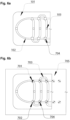
- a fourth embodiment of the invention is shown.
- the conduit forming element 101 comprises additional through openings 704 at junction points of the conduit forming channels 102.
- the underside of said conduit forming element 101 is positioned on top of a resting element 705 with elongated conduit shaping elements 702.
- the conduit shaping elements 702 are inserted into the underside of said conduit forming element 101 and are essentially aligned with the through openings 704.
- the conduit shaping elements 702 are passing through said through openings, in order to reshape the conduits in the conduit forming element and in order to close off the through openings towards the underside of the conduit forming element.
- the conduits form an interconnected network, with multiple connection points for each element.
- the conduits are further forming a single continuous fluid conduit through the use of redirecting conduits 703.
- a direct connection to a vacuum connector 701 can be obtained via an suitable inlet connector (not shown), in order to increase a pressure differential in a specific continuous fluid conduit thereby allowing remnant material to be cleaned much more effectively.
- This embodiment is particularly suitable for applications with fast drying, aqueous and/or solvent based inks/suspensions.
- the above described inlet connector is preferably configured to deliver a vapor or a liquid into the single continuous fluid conduit.
- the removal of additional material present in the interconnected conduit system may be a problem.
- the reshaping of said conduits essentially transforming a network with multiple connections into a single connected conduit, enables a much greater concentration of negative pressure on one end of said singular conduit, thereby increasing the pressure differential until remnant material can be removed effectively.
- a cleaning fluid may be introduced in order to wash away excess and hard to remove material in said singular conduit.
- nozzle flooding event In the nozzle flooding event occurs, impeding the ejection of liquid material, due to the presence of a large pendant drop of excess material 401, which has not been removed.
- the low-pressure conduit 201 has not created a large enough pressure differential with relation to the ambient pressure and/or dragging force in order to remove said excess material.
- Fig. 8 shows a sectional drawing of a fifth embodiment of the invention.
- the lower surface of the nozzle containing element is extended within the area of the nozzle well in such a fashion as to be essentially at a same height as the lower surface of the conduit forming element.
- the conduit openings 105 are essentially adjacent to the extended nozzle well and further connecting to said conduit 201 from the lower surface of said conduit forming element.
- secondary openings (108) are defined between the extended nozzle containing element and the pass-through opening 103, in close proximity to the nozzle opening.
- the secondary openings allow for removal of excess material. Once a pendant droplet has reached a sufficient size and essentially covers one or multiple secondary openings, the material is removed through the secondary opening.
- the problem addressed the above embodiment of the invention relates to the access of the lower surface of the nozzle containing element with cleaning elements such as wipers and other external systems to aid in removing material from the nozzle well area, when a transport of excess material cannot otherwise be facilitated.
- This embodiment thereby allows for a more effective removal of material that has been solidified and/or is otherwise impossible to remove within the confines of the other embodiments of the invention mentioned hereinabove.
Landscapes
- Engineering & Computer Science (AREA)
- Manufacturing & Machinery (AREA)
- Coating Apparatus (AREA)
- Ink Jet (AREA)
- Particle Formation And Scattering Control In Inkjet Printers (AREA)
Claims (11)
- Materialentfernungseinheit für einen Druckkopf (301), wobei die Einheit aufweist:eine Durchgangsöffnung (103), die unter einer Ausstoßöffnung (303) des Druckkopfs vorgesehen ist und so konfiguriert ist, dass ein ausgestoßenes Tröpfchen die Durchgangsöffnung im Wesentlichen ohne Beeinflussung passieren kann;mindestens einen kanalbildenden Kanal (102), der konfiguriert ist, einen Kanal (201) zu bilden;wobei der Kanal einen Bereich, der die Ausstoßöffnung umgibt, mit einem Anschlusspunkt (104) kommunikativ verbindet, der konfiguriert ist, überschüssiges Material aus dem Bereich, der die Ausstoßöffnung umgibt, zu entfernen;wobei der Kanal mindestens eine Kanalöffnung (105) in der Nähe der Durchgangsöffnung aufweist und konfiguriert ist, das Material zum Anschlusspunkt zu transportieren,wobei eine Antihaftbeschichtung in dem Kanal und/oder dem Bereich, der die Ausstoßöffnung umgibt, vorgesehen ist;dadurch gekennzeichnet, dassder mit einer Antihaftbeschichtung versehene Bereich zum Erzeugen eines anisotropen Ratschenförderers am Boden und/oder an der Oberseite des Kanals konfiguriert ist; undwobei der Kanal konfiguriert ist, den Ratschenförderer, der auf die mindestens eine Kanalöffnung gerichtet ist, durch Vibrationen des Druckkopfes zu unterstützen, die als Nebenprodukt der Betätigung des internen Mechanismus des Druckkopfes erzeugt werden.
- Materialentfernungseinheit nach Anspruch 1,wobei der Kanal konfiguriert ist, an der Anschlusspunkt mit einer Saugvorrichtung verbunden zu werden;konfiguriert ist, das überschüssige Material aus dem Bereich um die Ausstoßöffnung herum zu entfernen; undkonfiguriert ist, das Material in dem Kanal durch eine Schleppkraft zu transportieren; und/oderwobei ein Druckgradient in dem Kanal gebildet wird, wenn die Saugvorrichtung mit dem Anschlusspunktverbunden ist.
- Materialentfernungseinheit nach Anspruch 1 oder 2,wobei der Durchmesser der Durchgangsöffnung mindestens im Wesentlichen gleich oder vorzugsweise größer als ein Durchmesser der entsprechenden Ausstoßöffnung des Druckkopfes ist, und/oderwobei die Ausstoßöffnung im Wesentlichen in der Mitte der Durchgangsöffnung angeordnet ist.
- Materialentfernungseinheit nach einem der Ansprüche 1 bis 3,wobei der Kanal konfiguriert ist, das überschüssige Material zu einem Materialreservoir zu transportieren; und/oderwobei ein Materialreservoir mit dem Druckkopf in Verbindung steht, um das Material im Materialreservoir zu recyceln.
- Materialentfernungseinheit nach einem der Ansprüche 1 bis 4,wobei eine Düsenvertiefung in dem Bereich ausgebildet ist, der die Ausstoßöffnung umgibt; undwobei die Düsenvertiefung konfiguriert ist, einen Weg zu ermöglichen, damit Material, das eine vorbestimmte Größenschwelle überschreitet, zur Kanalöffnung geführt wird.
- Materialentfernungseinheit nach einem der Ansprüche 1 bis 5,
wobei die Antihaftbeschichtung eine vollständige oder eine mikrostrukturierte partielle Antihaftbeschichtung ist. - Materialentfernungseinheit nach Anspruch 6,
wobei die Antihaftbeschichtung in Form von gekrümmten Sprossen vorgesehen ist. - Materialentfernungseinheit nach einem der Ansprüche 1 bis 7,
wobei mindestens zwei Bereiche mit unterschiedlichen Oberflächenenergien um die Ausstoßöffnung herum in einer halbrunden Form vorgesehen sind. - Materialentfernungseinheit nach einem der Ansprüche 1 bis 8,wobei zusätzliche Öffnungen an Kreuzungspunkten der leitungsbildenden Kanäle vorgesehen sind; undwobei leitungsformende Elemente in den Öffnungen vorgesehen sind, um die in dem leitungsformenden Element gebildeten Kanäle umzuformen.
- Materialentfernungsverfahren für einen Druckkopf, wobei das Verfahren aufweist:Bereitstellen einer Materialentfernungseinheit nach einem der Ansprüche 1 bis 9;kommunikatives Verbinden, mit einem Kanal (201), eines Bereichs, der die Ausstoßöffnung umgibt, mit einem Anschlusspunkt (104), der konfiguriert ist, überschüssiges Material aus dem Bereich, der die Ausstoßöffnung (303) umgibt, zu entfernen; undTransportieren des überschüssigen Materials zu dem Anschlusspunkt basierend auf mindestens einem Transportverfahren;wobei der Kanal mindestens eine Kanalöffnung (105) nahe der Durchgangsöffnung (103) aufweist.
- Materialentfernungsverfahren für einen Druckkopf nach Anspruch 10, wobei das Transportverfahren auf einem Druckgradienten in dem Kanal basiert; und auf einem Ratschenförderer in dem Kanal und/oder einer Düsenvertiefung basiert.
Priority Applications (6)
| Application Number | Priority Date | Filing Date | Title |
|---|---|---|---|
| EP21215072.6A EP4197786B1 (de) | 2021-12-16 | 2021-12-16 | Verfahren und system für selbstwartung und rueckgewinnungssystem für einen druckkopf |
| JP2024535910A JP2024544296A (ja) | 2021-12-16 | 2022-11-17 | プリントヘッド用の自己保全回復システムのための方法およびシステム |
| KR1020247021966A KR20240121788A (ko) | 2021-12-16 | 2022-11-17 | 프린트헤드의 자가 유지보수 및 복구 시스템의 방법 및 시스템 |
| CN202280083340.8A CN118401375A (zh) | 2021-12-16 | 2022-11-17 | 用于打印头的自我维护和回收系统的方法和系统 |
| US18/719,623 US20250050639A1 (en) | 2021-12-16 | 2022-11-17 | Method and system for a self-maintenance and recovery system for a printhead |
| PCT/EP2022/082245 WO2023110276A1 (en) | 2021-12-16 | 2022-11-17 | Method and system for a self-maintenance and recovery system for a printhead |
Applications Claiming Priority (1)
| Application Number | Priority Date | Filing Date | Title |
|---|---|---|---|
| EP21215072.6A EP4197786B1 (de) | 2021-12-16 | 2021-12-16 | Verfahren und system für selbstwartung und rueckgewinnungssystem für einen druckkopf |
Publications (3)
| Publication Number | Publication Date |
|---|---|
| EP4197786A1 EP4197786A1 (de) | 2023-06-21 |
| EP4197786C0 EP4197786C0 (de) | 2025-03-12 |
| EP4197786B1 true EP4197786B1 (de) | 2025-03-12 |
Family
ID=78918636
Family Applications (1)
| Application Number | Title | Priority Date | Filing Date |
|---|---|---|---|
| EP21215072.6A Active EP4197786B1 (de) | 2021-12-16 | 2021-12-16 | Verfahren und system für selbstwartung und rueckgewinnungssystem für einen druckkopf |
Country Status (6)
| Country | Link |
|---|---|
| US (1) | US20250050639A1 (de) |
| EP (1) | EP4197786B1 (de) |
| JP (1) | JP2024544296A (de) |
| KR (1) | KR20240121788A (de) |
| CN (1) | CN118401375A (de) |
| WO (1) | WO2023110276A1 (de) |
Family Cites Families (10)
| Publication number | Priority date | Publication date | Assignee | Title |
|---|---|---|---|---|
| SE0202247D0 (sv) * | 2002-07-18 | 2002-07-18 | Mydata Automation Ab | Jetting device and method at a jetting device |
| JP5123881B2 (ja) * | 2008-06-05 | 2013-01-23 | エスアイアイ・プリンテック株式会社 | 液体噴射ヘッド、液体噴射記録装置及び液体噴射ヘッドの液体充填方法 |
| US8262192B2 (en) * | 2009-02-17 | 2012-09-11 | Fujifilm Corporation | Ink jet printer for printing electromagnetic wave curing ink |
| JP2011156770A (ja) * | 2010-02-01 | 2011-08-18 | Seiko Epson Corp | 液体噴射ヘッド、液体噴射ヘッドユニット及び液体噴射装置 |
| EP2566697B1 (de) * | 2010-05-02 | 2020-12-09 | Xjet Ltd. | Drucksystem mit anordnungen für selbstreinigung, ablagerungsverhinderung und rauchentfernung |
| JP5934161B2 (ja) * | 2013-09-09 | 2016-06-15 | 武蔵エンジニアリング株式会社 | ノズルおよび該ノズルを備える液体材料吐出装置 |
| JP6269259B2 (ja) * | 2014-03-31 | 2018-01-31 | ブラザー工業株式会社 | 液体噴射装置の製造方法、液体噴射装置、及び、撥液層形成方法 |
| US9878549B1 (en) * | 2016-12-21 | 2018-01-30 | Nano-Dimension Technologies | Devices, systems and methods for inkjet print head maintenance |
| NL2022897B1 (en) * | 2019-02-08 | 2020-10-15 | Canon Production Printing Holding Bv | Protective cover for an inkjet print head |
| EP3825100B1 (de) | 2019-11-19 | 2025-10-29 | Quantica GmbH | Materialausstosssystem, druckkopf, 3d-drucker und verfahren zur materialausstossung |
-
2021
- 2021-12-16 EP EP21215072.6A patent/EP4197786B1/de active Active
-
2022
- 2022-11-17 WO PCT/EP2022/082245 patent/WO2023110276A1/en not_active Ceased
- 2022-11-17 CN CN202280083340.8A patent/CN118401375A/zh active Pending
- 2022-11-17 US US18/719,623 patent/US20250050639A1/en active Pending
- 2022-11-17 KR KR1020247021966A patent/KR20240121788A/ko active Pending
- 2022-11-17 JP JP2024535910A patent/JP2024544296A/ja active Pending
Also Published As
| Publication number | Publication date |
|---|---|
| KR20240121788A (ko) | 2024-08-09 |
| US20250050639A1 (en) | 2025-02-13 |
| EP4197786C0 (de) | 2025-03-12 |
| CN118401375A (zh) | 2024-07-26 |
| EP4197786A1 (de) | 2023-06-21 |
| JP2024544296A (ja) | 2024-11-28 |
| WO2023110276A1 (en) | 2023-06-22 |
Similar Documents
| Publication | Publication Date | Title |
|---|---|---|
| KR101899604B1 (ko) | 자체-퍼지, 침전물 방지 및 연기 제거 장치를 구비한 프린팅 시스템 | |
| US6513903B2 (en) | Ink jet print head with capillary flow cleaning | |
| KR100274473B1 (ko) | 연속 인쇄 잉크 분사 노즐의 세척 장치 및 방법 | |
| EP3246165B1 (de) | Tintenstrahlkopf und tintenstrahlaufzeichnungsvorrichtung | |
| CN102427949B (zh) | 带有多孔捕集器的印刷头以及印刷方法 | |
| CN102196916A (zh) | 具有连续射流打印头的打印机和用于清洁该打印头的装置 | |
| US20110074869A1 (en) | Ink-jet wiping apparatus, and wiping method using this | |
| US20170282544A1 (en) | Single jet recirculation in an inkjet print head | |
| US8287093B2 (en) | Drop ejection assembly | |
| JPH0223350B2 (de) | ||
| CN102083629A (zh) | 液体喷射头、液体喷射记录装置以及液体喷射头的液体填充方法 | |
| CN102762384A (zh) | 包括在过滤器之后的端口的打印头 | |
| EP4197786B1 (de) | Verfahren und system für selbstwartung und rueckgewinnungssystem für einen druckkopf | |
| EP1273449A2 (de) | Flüssigkeitsausstosssystem mit wenig Verunreinigungen | |
| JP4882461B2 (ja) | フィルター装置及び液滴吐出装置 | |
| CN114051457B (zh) | 打印装置和打印系统 | |
| EP2345539A1 (de) | Flüssigkeitsausstosskopf, flüssigkeitsaufnahmeverfahren für den flüssigkeitsausstosskopf, flüssigkeitsausstoss-aufzeichnungsvorrichtung sowie verfahren zu ihrer verwendung | |
| WO2005065378A2 (en) | Drop ejection assembly | |
| US7883174B2 (en) | Cover for fluid jetting device and method for enhancing fluid performance | |
| JP6615048B2 (ja) | ノズルエリアに高粘度材料を補充するように構成されるプリントヘッド | |
| CN110525049A (zh) | 液体喷出装置以及液体喷出装置的控制方法 | |
| US7303259B2 (en) | Drop ejection assembly | |
| US20100328396A1 (en) | Flow through dispenser including two dimensional array | |
| CN102267288B (zh) | 喷射用液体干燥抑制装置、方法及液体喷射装置 | |
| JP5428917B2 (ja) | 流体噴射装置及びワイピング方法 |
Legal Events
| Date | Code | Title | Description |
|---|---|---|---|
| PUAI | Public reference made under article 153(3) epc to a published international application that has entered the european phase |
Free format text: ORIGINAL CODE: 0009012 |
|
| STAA | Information on the status of an ep patent application or granted ep patent |
Free format text: STATUS: THE APPLICATION HAS BEEN PUBLISHED |
|
| AK | Designated contracting states |
Kind code of ref document: A1 Designated state(s): AL AT BE BG CH CY CZ DE DK EE ES FI FR GB GR HR HU IE IS IT LI LT LU LV MC MK MT NL NO PL PT RO RS SE SI SK SM TR |
|
| STAA | Information on the status of an ep patent application or granted ep patent |
Free format text: STATUS: REQUEST FOR EXAMINATION WAS MADE |
|
| 17P | Request for examination filed |
Effective date: 20231220 |
|
| RBV | Designated contracting states (corrected) |
Designated state(s): AL AT BE BG CH CY CZ DE DK EE ES FI FR GB GR HR HU IE IS IT LI LT LU LV MC MK MT NL NO PL PT RO RS SE SI SK SM TR |
|
| REG | Reference to a national code |
Ref country code: DE Ref legal event code: R079 Free format text: PREVIOUS MAIN CLASS: B41J0002140000 Ipc: B05B0015520000 Ref country code: DE Ref legal event code: R079 Ref document number: 602021027455 Country of ref document: DE Free format text: PREVIOUS MAIN CLASS: B41J0002140000 Ipc: B05B0015520000 |
|
| GRAP | Despatch of communication of intention to grant a patent |
Free format text: ORIGINAL CODE: EPIDOSNIGR1 |
|
| STAA | Information on the status of an ep patent application or granted ep patent |
Free format text: STATUS: GRANT OF PATENT IS INTENDED |
|
| RIC1 | Information provided on ipc code assigned before grant |
Ipc: B41J 2/16 20060101ALI20240917BHEP Ipc: B41J 2/14 20060101ALI20240917BHEP Ipc: B05B 15/52 20180101AFI20240917BHEP |
|
| INTG | Intention to grant announced |
Effective date: 20240930 |
|
| GRAS | Grant fee paid |
Free format text: ORIGINAL CODE: EPIDOSNIGR3 |
|
| GRAA | (expected) grant |
Free format text: ORIGINAL CODE: 0009210 |
|
| STAA | Information on the status of an ep patent application or granted ep patent |
Free format text: STATUS: THE PATENT HAS BEEN GRANTED |
|
| AK | Designated contracting states |
Kind code of ref document: B1 Designated state(s): AL AT BE BG CH CY CZ DE DK EE ES FI FR GB GR HR HU IE IS IT LI LT LU LV MC MK MT NL NO PL PT RO RS SE SI SK SM TR |
|
| REG | Reference to a national code |
Ref country code: GB Ref legal event code: FG4D |
|
| REG | Reference to a national code |
Ref country code: CH Ref legal event code: EP |
|
| REG | Reference to a national code |
Ref country code: DE Ref legal event code: R096 Ref document number: 602021027455 Country of ref document: DE |
|
| REG | Reference to a national code |
Ref country code: IE Ref legal event code: FG4D |
|
| U01 | Request for unitary effect filed |
Effective date: 20250319 |
|
| U07 | Unitary effect registered |
Designated state(s): AT BE BG DE DK EE FI FR IT LT LU LV MT NL PT RO SE SI Effective date: 20250324 |
|
| PG25 | Lapsed in a contracting state [announced via postgrant information from national office to epo] |
Ref country code: RS Free format text: LAPSE BECAUSE OF FAILURE TO SUBMIT A TRANSLATION OF THE DESCRIPTION OR TO PAY THE FEE WITHIN THE PRESCRIBED TIME-LIMIT Effective date: 20250612 |
|
| PG25 | Lapsed in a contracting state [announced via postgrant information from national office to epo] |
Ref country code: ES Free format text: LAPSE BECAUSE OF FAILURE TO SUBMIT A TRANSLATION OF THE DESCRIPTION OR TO PAY THE FEE WITHIN THE PRESCRIBED TIME-LIMIT Effective date: 20250312 |
|
| PG25 | Lapsed in a contracting state [announced via postgrant information from national office to epo] |
Ref country code: NO Free format text: LAPSE BECAUSE OF FAILURE TO SUBMIT A TRANSLATION OF THE DESCRIPTION OR TO PAY THE FEE WITHIN THE PRESCRIBED TIME-LIMIT Effective date: 20250612 |
|
| PG25 | Lapsed in a contracting state [announced via postgrant information from national office to epo] |
Ref country code: HR Free format text: LAPSE BECAUSE OF FAILURE TO SUBMIT A TRANSLATION OF THE DESCRIPTION OR TO PAY THE FEE WITHIN THE PRESCRIBED TIME-LIMIT Effective date: 20250312 |
|
| PG25 | Lapsed in a contracting state [announced via postgrant information from national office to epo] |
Ref country code: GR Free format text: LAPSE BECAUSE OF FAILURE TO SUBMIT A TRANSLATION OF THE DESCRIPTION OR TO PAY THE FEE WITHIN THE PRESCRIBED TIME-LIMIT Effective date: 20250613 |
|
| PG25 | Lapsed in a contracting state [announced via postgrant information from national office to epo] |
Ref country code: SM Free format text: LAPSE BECAUSE OF FAILURE TO SUBMIT A TRANSLATION OF THE DESCRIPTION OR TO PAY THE FEE WITHIN THE PRESCRIBED TIME-LIMIT Effective date: 20250312 |
|
| PG25 | Lapsed in a contracting state [announced via postgrant information from national office to epo] |
Ref country code: PL Free format text: LAPSE BECAUSE OF FAILURE TO SUBMIT A TRANSLATION OF THE DESCRIPTION OR TO PAY THE FEE WITHIN THE PRESCRIBED TIME-LIMIT Effective date: 20250312 |
|
| PG25 | Lapsed in a contracting state [announced via postgrant information from national office to epo] |
Ref country code: CZ Free format text: LAPSE BECAUSE OF FAILURE TO SUBMIT A TRANSLATION OF THE DESCRIPTION OR TO PAY THE FEE WITHIN THE PRESCRIBED TIME-LIMIT Effective date: 20250312 |
|
| PG25 | Lapsed in a contracting state [announced via postgrant information from national office to epo] |
Ref country code: SK Free format text: LAPSE BECAUSE OF FAILURE TO SUBMIT A TRANSLATION OF THE DESCRIPTION OR TO PAY THE FEE WITHIN THE PRESCRIBED TIME-LIMIT Effective date: 20250312 |
|
| PG25 | Lapsed in a contracting state [announced via postgrant information from national office to epo] |
Ref country code: IS Free format text: LAPSE BECAUSE OF FAILURE TO SUBMIT A TRANSLATION OF THE DESCRIPTION OR TO PAY THE FEE WITHIN THE PRESCRIBED TIME-LIMIT Effective date: 20250712 |
|
| U1N | Appointed representative for the unitary patent procedure changed after the registration of the unitary effect |
Representative=s name: PAUSTIAN & PARTNER PATENTANWAELTE MBB; DE |
|
| PLBE | No opposition filed within time limit |
Free format text: ORIGINAL CODE: 0009261 |
|
| STAA | Information on the status of an ep patent application or granted ep patent |
Free format text: STATUS: NO OPPOSITION FILED WITHIN TIME LIMIT |
|
| REG | Reference to a national code |
Ref country code: CH Ref legal event code: L10 Free format text: ST27 STATUS EVENT CODE: U-0-0-L10-L00 (AS PROVIDED BY THE NATIONAL OFFICE) Effective date: 20260121 |
|
| U20 | Renewal fee for the european patent with unitary effect paid |
Year of fee payment: 5 Effective date: 20251222 |
|
| 26N | No opposition filed |
Effective date: 20251215 |
|
| PGFP | Annual fee paid to national office [announced via postgrant information from national office to epo] |
Ref country code: GB Payment date: 20260217 Year of fee payment: 5 |