EP4197821B1 - Système et procédé d'estimation de rigidité de pneu - Google Patents
Système et procédé d'estimation de rigidité de pneu Download PDFInfo
- Publication number
- EP4197821B1 EP4197821B1 EP22212288.9A EP22212288A EP4197821B1 EP 4197821 B1 EP4197821 B1 EP 4197821B1 EP 22212288 A EP22212288 A EP 22212288A EP 4197821 B1 EP4197821 B1 EP 4197821B1
- Authority
- EP
- European Patent Office
- Prior art keywords
- vehicle
- tire
- vector
- data
- processor
- Prior art date
- Legal status (The legal status is an assumption and is not a legal conclusion. Google has not performed a legal analysis and makes no representation as to the accuracy of the status listed.)
- Active
Links
Images



Classifications
-
- B—PERFORMING OPERATIONS; TRANSPORTING
- B60—VEHICLES IN GENERAL
- B60C—VEHICLE TYRES; TYRE INFLATION; TYRE CHANGING; CONNECTING VALVES TO INFLATABLE ELASTIC BODIES IN GENERAL; DEVICES OR ARRANGEMENTS RELATED TO TYRES
- B60C11/00—Tyre tread bands; Tread patterns; Anti-skid inserts
- B60C11/24—Wear-indicating arrangements
- B60C11/246—Tread wear monitoring systems
-
- B—PERFORMING OPERATIONS; TRANSPORTING
- B60—VEHICLES IN GENERAL
- B60W—CONJOINT CONTROL OF VEHICLE SUB-UNITS OF DIFFERENT TYPE OR DIFFERENT FUNCTION; CONTROL SYSTEMS SPECIALLY ADAPTED FOR HYBRID VEHICLES; ROAD VEHICLE DRIVE CONTROL SYSTEMS FOR PURPOSES NOT RELATED TO THE CONTROL OF A PARTICULAR SUB-UNIT
- B60W40/00—Estimation or calculation of non-directly measurable driving parameters for road vehicle drive control systems not related to the control of a particular sub unit, e.g. by using mathematical models
- B60W40/12—Estimation or calculation of non-directly measurable driving parameters for road vehicle drive control systems not related to the control of a particular sub unit, e.g. by using mathematical models related to parameters of the vehicle itself, e.g. tyre models
-
- G—PHYSICS
- G01—MEASURING; TESTING
- G01M—TESTING STATIC OR DYNAMIC BALANCE OF MACHINES OR STRUCTURES; TESTING OF STRUCTURES OR APPARATUS, NOT OTHERWISE PROVIDED FOR
- G01M17/00—Testing of vehicles
- G01M17/007—Wheeled or endless-tracked vehicles
- G01M17/02—Tyres
-
- G—PHYSICS
- G01—MEASURING; TESTING
- G01P—MEASURING LINEAR OR ANGULAR SPEED, ACCELERATION, DECELERATION, OR SHOCK; INDICATING PRESENCE, ABSENCE, OR DIRECTION, OF MOVEMENT
- G01P15/00—Measuring acceleration; Measuring deceleration; Measuring shock, i.e. sudden change of acceleration
-
- B—PERFORMING OPERATIONS; TRANSPORTING
- B60—VEHICLES IN GENERAL
- B60W—CONJOINT CONTROL OF VEHICLE SUB-UNITS OF DIFFERENT TYPE OR DIFFERENT FUNCTION; CONTROL SYSTEMS SPECIALLY ADAPTED FOR HYBRID VEHICLES; ROAD VEHICLE DRIVE CONTROL SYSTEMS FOR PURPOSES NOT RELATED TO THE CONTROL OF A PARTICULAR SUB-UNIT
- B60W2520/00—Input parameters relating to overall vehicle dynamics
- B60W2520/10—Longitudinal speed
-
- B—PERFORMING OPERATIONS; TRANSPORTING
- B60—VEHICLES IN GENERAL
- B60W—CONJOINT CONTROL OF VEHICLE SUB-UNITS OF DIFFERENT TYPE OR DIFFERENT FUNCTION; CONTROL SYSTEMS SPECIALLY ADAPTED FOR HYBRID VEHICLES; ROAD VEHICLE DRIVE CONTROL SYSTEMS FOR PURPOSES NOT RELATED TO THE CONTROL OF A PARTICULAR SUB-UNIT
- B60W2520/00—Input parameters relating to overall vehicle dynamics
- B60W2520/10—Longitudinal speed
- B60W2520/105—Longitudinal acceleration
-
- B—PERFORMING OPERATIONS; TRANSPORTING
- B60—VEHICLES IN GENERAL
- B60W—CONJOINT CONTROL OF VEHICLE SUB-UNITS OF DIFFERENT TYPE OR DIFFERENT FUNCTION; CONTROL SYSTEMS SPECIALLY ADAPTED FOR HYBRID VEHICLES; ROAD VEHICLE DRIVE CONTROL SYSTEMS FOR PURPOSES NOT RELATED TO THE CONTROL OF A PARTICULAR SUB-UNIT
- B60W2520/00—Input parameters relating to overall vehicle dynamics
- B60W2520/26—Wheel slip
-
- B—PERFORMING OPERATIONS; TRANSPORTING
- B60—VEHICLES IN GENERAL
- B60W—CONJOINT CONTROL OF VEHICLE SUB-UNITS OF DIFFERENT TYPE OR DIFFERENT FUNCTION; CONTROL SYSTEMS SPECIALLY ADAPTED FOR HYBRID VEHICLES; ROAD VEHICLE DRIVE CONTROL SYSTEMS FOR PURPOSES NOT RELATED TO THE CONTROL OF A PARTICULAR SUB-UNIT
- B60W2720/00—Output or target parameters relating to overall vehicle dynamics
-
- B—PERFORMING OPERATIONS; TRANSPORTING
- B60—VEHICLES IN GENERAL
- B60W—CONJOINT CONTROL OF VEHICLE SUB-UNITS OF DIFFERENT TYPE OR DIFFERENT FUNCTION; CONTROL SYSTEMS SPECIALLY ADAPTED FOR HYBRID VEHICLES; ROAD VEHICLE DRIVE CONTROL SYSTEMS FOR PURPOSES NOT RELATED TO THE CONTROL OF A PARTICULAR SUB-UNIT
- B60W2720/00—Output or target parameters relating to overall vehicle dynamics
- B60W2720/28—Wheel speed
Definitions
- the invention relates generally to tire monitoring and estimation systems and methods. More particularly, the invention relates to systems and methods that predict certain tire characteristics. Specifically, the invention is directed to a system and a method for estimating the stiffness of a tire in real time.
- a vehicle is supported by multiple tires.
- the stiffness of each tire affects the performance and characteristics of the tire during operation of the vehicle.
- longitudinal stiffness of the tire which is the stiffness of the tire in its longitudinal or travel direction, may be employed to distinguish between different road surface conditions and/or different wear states of the tire.
- longitudinal stiffness may be employed to improve the operation of vehicle control systems, such as adaptive cruise control (ACC), anti-lock braking systems (ABS), electronic stability program (ESP), acceleration slip regulation (ASR), and the like.
- ACC adaptive cruise control
- ABS anti-lock braking systems
- ESP electronic stability program
- ASR acceleration slip regulation
- complex systems may be undesirably difficult to implement.
- complex systems require a significant amount of computing load.
- such systems may not be able to be executed on a vehicle-mounted processor, thereby undesirably requiring additional resources such as cloud computing, and undesirably taking significant time to generate a real-time estimate.
- the invention relates to a system in accordance with claim 1 and to a method in accordance with claim 15.
- a longitudinal stiffness estimation system for at least one tire supporting a vehicle.
- the system includes an electronic communication system that is disposed on the vehicle, and at least one sensor disposed on the vehicle which is in electronic communication with the electronic communication system.
- a processor is accessible through the electronic communication system.
- the sensor measures selected parameters associated with the vehicle and communicates data for the selected parameters through the electronic communication system to the processor.
- a ⁇ -slip curve generator is in communication with the processor, receives the selected parameters, and generates a ⁇ -slip curve in real time from the communicated data.
- An extraction module is in communication with the processor and extracts raw data from a linear portion of the ⁇ -slip curve.
- a denoising module is in communication with the processor and de-noises the raw data from the ⁇ -slip curve by determining a vector for the raw data, an orientation of the vector, and a heading of the vector.
- the denoising module generates de-noised data
- a stiffness calculator receives the de-noised data and generates a longitudinal stiffness estimate for the tire.
- ANN Artificial Neural Network
- ANN neural networks are non-linear statistical data modeling tools used to model complex relationships between inputs and outputs or to find patterns in data.
- Axial and “axially” means lines or directions that are parallel to the axis of rotation of the tire.
- CAN is an abbreviation for controller area network, and is used in conjunction with CAN bus, which is an electronic communication system on a vehicle.
- “Circumferential” means lines or directions extending along the perimeter of the surface of the annular tread of the tire perpendicular to the axial direction.
- Cloud computing means computer processing involving computing power and/or data storage that is distributed across multiple data centers, which is typically facilitated by access and communication using the Internet.
- Inboard side means the side of the tire nearest the vehicle when the tire is mounted on a wheel and the wheel is mounted on the vehicle.
- Kalman filter is a set of mathematical equations that implement a predictor-corrector type estimator that is optimal in the sense that it minimizes the estimated error covariance when some presumed conditions are met.
- “Lateral” means an axial direction.
- “Luenberger observer” is a state observer or estimation model.
- a “state observer” is a system that provide an estimate of the internal state of a given real system, from measurements of the input and output of the real system. It is typically computer-implemented, and provides the basis of many practical applications.
- MSE is an abbreviation for mean square error, the error between and a measured signal and an estimated signal which the Kalman filter minimizes.
- Outboard side means the side of the tire farthest away from the vehicle when the tire is mounted on a wheel and the wheel is mounted on the vehicle.
- Ring and radially means directions radially toward or away from the axis of rotation of the tire.
- TPMS means a tire pressure monitoring system
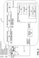
- FIG. 1-9 An exemplary embodiment of the longitudinal stiffness estimation system 10 of the present invention is presented in Figures 1-9 .
- the system 10 estimates a longitudinal stiffness of a tire 12 that supports a vehicle 14, as shown in Figure 1 . While the vehicle 14 is depicted as a passenger car, the invention is not to be so restricted. The principles of the invention find application in other vehicle categories, such as commercial trucks, in which vehicles may be supported by more or fewer tires.
- Each tire 12 is preferably of conventional construction, and is mounted on a wheel 16. Each tire 12 preferably includes a pair of sidewalls 18 that extend to a circumferential tread 20. Each tire 12 is preferably equipped with a sensor or transducer 24, which may be a tire pressure monitoring (TPMS) module or sensor, and detects tire parameters such as pressure within a tire cavity 21 and tire temperature.
- TPMS tire pressure monitoring
- the sensor 24 preferably is affixed to an inner liner 22 of the tire 12 by suitable means such as adhesive.
- the tire 12 includes a longitudinal stiffness, which is its stiffness in a longitudinal or travel direction.
- the longitudinal stiffness estimation system 10 calculates the longitudinal stiffness of the tire 12 by providing a longitudinal stiffness estimate 52. Aspects of the longitudinal stiffness estimation system 10 preferably are executed on a processor 26 that is accessible through an electronic communication system on the vehicle, which enables central communication between multiple vehicle sensors, such as a CAN bus system 28.
- the processor 26 may be a local processor that is mounted on the vehicle 14, or may be a remote processor, such as a cloud computing processor.
- the longitudinal stiffness estimation system 10 preferably provides a longitudinal stiffness estimate 52 for each tire 12 mounted on a driven wheel 16 of the vehicle 14. For example, in a front wheel drive vehicle 14, the system 10 generates a stiffness estimate 52 for each one of the front tires 12. For the purpose of convenience, the system 10 is described with reference to one tire 12, with the understanding that an estimate 52 preferably is provided for each tire 12 mounted on a driven wheel 16 of the vehicle 14.
- the longitudinal stiffness estimation system 10 receives as inputs certain parameters measured by sensors that are mounted on the vehicle 14 and which are in electronic communication with the vehicle CAN bus system 28.
- the CAN bus 28 electronically communicates a longitudinal acceleration (A x or a x ) 30 of the vehicle 14, a wheel speed 32, a throttle or gas pedal position 34, a brake pedal position 36, and a vehicle reference speed 38, to an acceleration module 40 and a ⁇ -slip curve generator 42.
- the vehicle reference speed 38 may be obtained from a global positioning system (GPS) or other reliable source of the vehicle reference speed.
- GPS global positioning system
- the gas pedal position 34 and brake pedal position 36 are employed to confirm that the vehicle 14 is accelerating. For example, if the gas pedal position 34 is below a predetermined throttle threshold, or if the brake pedal position 36 is above a predetermined brake threshold, the system 10 determines that the vehicle 14 is not accelerating. When the vehicle 14 is not accelerating, the system 10 does not proceed to the ⁇ -slip curve generator 42. If the gas pedal position 34 is greater than a predetermined throttle threshold and/or the brake pedal position 36 is below a predetermined brake threshold, the system 10 determines that the vehicle 14 is accelerating and proceeds to the ⁇ -slip curve generator 42.
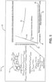
- the ⁇ -slip curve generator 42 generates a ⁇ -slip curve 44 in real time.
- the ⁇ -slip curve 44 plots the frictional force between the tire 12 and the surface on which the tire is traveling, represented by the coefficient of friction mu ( ⁇ ).
- the ⁇ -slip curve generator 42 employs the longitudinal acceleration 30 of the vehicle 14 to approximate the coefficient of friction ⁇ during vehicle acceleration.
- the ⁇ -slip curve 44 plots tire slip 46, which is the relative motion between the tire 12 and the surface on which the tire is traveling.
- the ⁇ -slip curve generator 42 of the longitudinal stiffness estimation system 10 generates a ⁇ -slip curve 44 in real time using input signals from the vehicle CAN bus system 28.
- a slope 48 of a linear portion 50 of the ⁇ -slip curve 44 corresponds to the longitudinal stiffness of the tire 12.
- the longitudinal stiffness estimation system 10 extracts the longitudinal stiffness of the tire 12 and provides a longitudinal stiffness estimate 52 in an accurate manner.
- an extraction module 54 extracts raw data 56 from the linear portion 50 of the ⁇ -slip curve 44.
- the raw data 56 includes signal noise, that is, unwanted modifications in the data that occur during capture, storage, transmission, and/or processing. As a result, the raw data 56 must be de-noised or cleaned to improve its accuracy. It is to be understood that the data shown in Figures 4-9 may include hypothetical representations by way of example for the purpose of illustrating the principles of the invention.
- a denoising module 58 de-noises or cleans the raw data 56.
- Denoising module 58 preferably applies principal component analysis (PCA) to determine patterns from the raw data 56 for prediction analysis.
- PCA principal component analysis
- PCA identifies a principal component or eigenvector, which is a characteristic vector of a linear transformation of the raw data 56. In this manner, a pattern that is visualized or represented by a vector 60 is determined from the raw data 56.
- the PCA of the denoising module 58 predicts an orientation 62 of the vector 60, which corresponds to the data variance, rather than predicting each value of the raw data 56.
- the orientation of the vector 60 and the raw data 56 is determined using the first principal component of the raw data.
- another parameter referred to as a heading of the vector 60 which is indicated at theta ( ⁇ ) is determined.
- the heading ⁇ enables an accurate fit of the vector 60 to be obtained that covers the variance of the data.
- the heading ⁇ is the angle between a horizontal line 64 extending from an origin of ⁇ and the orientation 62 of the vector 60.
- the heading ⁇ must reflect a proper alignment of the vector 60 with the data. Since the heading ⁇ is initially an unknown value, a density module 66 is employed to determine the heading. In the density module 66, the determination of an optimum value for the heading ⁇ is driven by the data.
- the data are transformed to polar coordinates 68 and a density versus heading ⁇ plot 72 is generated. Density is indicated by rho ( ⁇ ). Because the data are symmetric, positive values may be used for simplicity. In addition, because the data are not continuous, the first ten percent (10%) of the standard deviation of the data is used to select a data range 70.
- the density ⁇ of the data range 70 is calculated based on a median of the data: med x ⁇ 0.1 ⁇ x ⁇ x _ selected ⁇ med x + 0.1 ⁇ x
- a density center of the data range 70 is determined using the median of the headings ⁇ , which corresponds to the optimum value for the heading.
- the data range 70 is transformed back to the ⁇ versus slip 46 plot and the orientation 62 of the vector 60 is calculated using the polar coordinates. Specifically, the coefficient of a second polar axis PC2 is divided by the coefficient of a first polar axis PC1 to determine the orientation 62. In this manner, the orientation 62 and the heading ⁇ for the vector 60 are determined, thus de-noising the data 74.
- a stiffness calculator 76 ascertains a slope of the vector.
- the slope of the vector 60 is the longitudinal stiffness estimate 52 for the tire 12.
- the longitudinal stiffness estimate 52 is communicated by the CAN bus system 28 to other vehicle control systems for use in such systems and/or to determine certain conditions of the tire 12.
- the longitudinal stiffness estimate 52 may be used in a road state monitor 106 to monitor the condition of a road surface over which the tire 12 travels by distinguishing between different road surface conditions 88.
- the stiffness 52 of the tire 12 exhibits fast time-varying characteristics on different road surface conditions 88. More particularly, in a non-temperature compensated plot 78, each tire stiffness estimate 52 is different for a summer tire 80, an all-season tire 82, and a winter tire 84 on a dry surface 90, a wet surface 92, a snow-covered surface 94, and an icy surface 96, respectively.
- tire stiffness is sensitive to temperature, it is important to correct the tire stiffness estimate 52 for the influence of temperature, as shown in temperature-compensated plot 86. From the temperature-compensated plot 86, it can be seen that temperature compensation may exaggerate the differences in the stiffness estimate 52, particularly for the summer tire 80 and the all-season tire 82. In addition, it can be seen that the stiffness estimate 52 for the winter tire 84 generally exhibits a lower dependence on the type of road surface 88, while the stiffness estimate for the summer tire 80 and the all-season tire 82 is higher on an icy surface 96 than on a snow-covered surface 94. Based on this information, the longitudinal stiffness estimate 52 may thus be used by the road surface monitor 106 to distinguish between a dry road surface 90, a wet road surface 92, a snow-covered road surface 94, and an icy road surface 96.
- the longitudinal stiffness estimate 52 may be used in a wear state monitor 108 to monitor the wear state of the tire 12 by distinguishing between different wear states.
- the stiffness 52 of the tire 12 exhibits slow time-varying characteristics with wear. More particularly, in ⁇ versus slip plots 98 for worn tires 100, the stiffness estimates 52 were at least thirty percent (30%) higher than the stiffness estimates in ⁇ versus slip plots 102 for worn tires 104. Based on this information, the longitudinal stiffness estimate 52 may thus be used by the wear state monitor 108 to distinguish between different wear states of the tire 12.
- the longitudinal stiffness estimation system 10 of the present invention provides a stiffness estimate 52 for a tire 12 in real time based on input signals from a standard vehicle system, such as the CAN bus system 28.
- the longitudinal stiffness estimation system 10 of the present invention thus provides an accurate stiffness estimate 52 based on minimal data sources.
- the use of the above-described denoising module 58 in the longitudinal stiffness estimation system 10 involves a low computing load and may thus be executed on a vehicle-based processor 26, as opposed to prior art systems that involve high computing loads and must be executed remotely.
- the present invention also includes a method of estimating the longitudinal stiffness of a tire 12.
- the method includes steps in accordance with the description that is presented above and shown in Figures 1 through 9 .
- the longitudinal stiffness estimation system 10 of the present invention and the accompanying method may be referred to as a Nouri technique.
- stiffness estimation system 10 may be altered or rearranged, or components or steps known to those skilled in the art omitted or added, without affecting the overall concept or operation of the invention.
- the system 10 is described above using an acceleration condition of the vehicle 14, the system may be applied to cruising and braking conditions without affecting the overall concept or operation of the invention.
Landscapes
- Engineering & Computer Science (AREA)
- Physics & Mathematics (AREA)
- General Physics & Mathematics (AREA)
- Mechanical Engineering (AREA)
- Automation & Control Theory (AREA)
- Mathematical Physics (AREA)
- Transportation (AREA)
- Tires In General (AREA)
Claims (15)
- Système d'estimation de la rigidité longitudinale destiné à au moins un bandage pneumatique (12) qui supporte un véhicule (14), le système d'estimation de la rigidité longitudinale (10) comprenant :un système (28) de mise en communication par voie électronique qui est disposé sur le véhicule (14) ;au moins un capteur (24) qui est disposé sur le véhicule (14) et qui est mis en communication par voie électronique avec le système (28) de mise en communication par voie électronique ; etun processeur (26) qui est accessible par le biais du système (28) de mise en communication par voie électronique ;ledit au moins un capteur (24) étant configuré pour mesurer des paramètres sélectionnés qui sont associés au véhicule (14) et pour communiquer des données concernant les paramètres sélectionnés par le biais du système (28) de mise en communication par voie électronique au processeur (26) ;caractérisé en ce que le système comprend en outre :un générateur (42) d'une courbe de dérapage par rapport au coefficient de friction µ mis en communication avec le processeur (26) et configuré pour recevoir les paramètres qui ont été sélectionnés et pour générer une courbe de dérapage par rapport au coefficient de friction µ (44) en temps réel à partir des données qui ont été communiquées ;un module d'extraction (54) mis en communication avec le processeur (26) et configuré pour extraire des données brutes à partir d'une portion linéaire (50) de la courbe de dérapage par rapport au coefficient de friction µ (44) ;un module de suppression des nuisances sonores (66) mis en communication avec le processeur (26) et configuré pour la suppression des nuisances sonores des données brutes (56) à partir de la courbe de dérapage par rapport au coefficient de friction µ (44) en déterminant un tracé à partir des données brutes (56), représenté par un vecteur (60), une orientation du vecteur (60) et une direction du vecteur (60) ; dans lequel le module de suppression des nuisances sonores (66) est configuré pour générer des données (74) qui ont fait l'objet d'une suppression des nuisances sonores ; etun calculateur de la rigidité (76) qui est configuré pour recevoir les données (74) qui ont fait l'objet d'une suppression des nuisances sonores et pour générer une estimation (52) de la rigidité longitudinale pour ledit au moins un bandage pneumatique (12).
- Système selon la revendication 1, dans lequel les paramètres qui ont été sélectionnés englobent au moins un paramètre choisi parmi une accélération longitudinale (30) du véhicule (14), une vitesse (32) de la roue, et une vitesse de référence du véhicule (38), et, de manière facultative, dans lequel le générateur (42) d'une courbe de dérapage par rapport au coefficient de friction µ est configuré pour recevoir l'accélération longitudinale (32) véhicule (14) afin d'obtenir un coefficient de friction µ approximatif dans la courbe de dérapage par rapport au coefficient de friction µ à titre de coefficient de friction entre le bandage pneumatique (12) et une surface sur laquelle se déplace le bandage pneumatique (12).
- Système selon la revendication 1 ou 2, dans lequel le générateur (42) d'une courbe de dérapage par rapport au coefficient de friction µ est configuré pour recevoir une vitesse de roue (32) et une vitesse de référence de véhicule (38) pour calculer le dérapage dans la courbe de dérapage par rapport au coefficient de friction µ.
- Système selon au moins une des revendications précédentes, qui comprend en outre un module d'accélération (40), le module d'accélération (40) étant configuré pour recevoir une position de l'accélérateur (34) et une position de la pédale de frein (36) afin de déterminer le fait de savoir si le véhicule (14) accélère ou non.
- Système selon au moins une des revendications précédentes, dans lequel le tracé est déterminé sous la forme d'un vecteur caractéristique des données brutes.
- Système selon au moins une des revendications précédentes, dans lequel la direction du vecteur (60) représente un angle formé entre une ligne horizontale qui s'étend à partir d'une origine de µ dans la courbe de dérapage par rapport au coefficient de friction µ (44) et l'orientation du vecteur (60).
- Système selon au moins une des revendications précédentes, dans lequel le module de suppression des nuisances sonores (58) englobe un module de densité (66) qui est destiné à déterminer la direction du vecteur (60), le module de densité (66) étant configuré pour transformer les données brutes (56) en coordonnées polaires et pour générer un un graphique de la densité en fonction de la direction, et, de manière facultative, le module de densité étant configuré pour déterminer une plage de données sélectionnées dans le graphique de la densité en fonction de la direction et pour calculer une densité de la plage de données sélectionnées en se basant sur une médiane de la plage de données sélectionnées.
- Système selon la revendication 7, dans lequel le module de densité (66) est configuré pour déterminer un centre de densité de la plage de données sélectionnées, le centre de densité correspondant à une valeur optimale pour la direction du vecteur (60).
- Système selon au moins une des revendications précédentes, dans lequel le module de suppression des nuisances sonores (58) est configuré pour déterminer une orientation du vecteur (60) en utilisant des coordonnées polaires, de préférence en divisant un coefficient d'un second axe polaire par un coefficient d'un premier axe polaire afin de déterminer l'orientation du vecteur.
- Système selon au moins une des revendications précédentes, dans lequel le calculateur de la rigidité (76) est configuré pour déterminer une pente du vecteur afin de générer l'estimation de la rigidité longitudinale (52).
- Système selon au moins une des revendications précédentes, dans lequel le processeur (26) est monté sur le véhicule (14) ; ou dans lequel le processeur (26) représente un processeur pour l'informatique en nuage ; et/ou dans lequel l'estimation de la rigidité longitudinale (52) est communiquée par le biais du système (28) de mise en communication par voie électronique à un système de commande du véhicule.
- Système selon au moins une des revendications précédentes, dans lequel le système (10) est configuré pour procurer une estimation de la rigidité longitudinale (50) pour chaque bandage pneumatique (12) qui est monté sur une roue motrice du véhicule (14).
- Système selon au moins une des revendications précédentes, qui comprend en outre un dispositif de surveillance (106) de l'état de la surface de la route, dans lequel le dispositif de surveillance (106) de l'état de la surface de la route est configuré pour recevoir un certain nombre d'estimations de la rigidité longitudinale ; et, en se basant sur des caractéristiques des estimations de la rigidité longitudinale, qui varient dans le temps, le dispositif de surveillance de l'état de la surface de la route est configuré pour opérer une distinction entre au moins deux surfaces de route choisies parmi une surface de route sèche, une surface de route mouillée, une surface de route recouverte de neige et une surface de route verglacée ; et, de manière facultative, dans lequel le dispositif de surveillance (106) de l'état de la surface de la route englobe en outre une correction de la température pour chaque estimation de la rigidité longitudinale (52).
- Système selon au moins une des revendications précédentes, qui comprend en outre un dispositif de surveillance de l'état d'usure (108), dans lequel le dispositif de surveillance de l'état d'usure (108) est configuré pour recevoir un certain nombre d'estimations de la rigidité longitudinale ; et, en se basant sur des caractéristiques des estimations de la rigidité longitudinale, qui varient dans le temps, le dispositif de surveillance de l'état d'usure est configuré pour opérer une distinction entre différents états d'usure du bandage pneumatique (12) ; et, de manière facultative, dans lequel le dispositif de surveillance de l'état d'usure est configuré pour opérer une distinction entre différents états d'usure du bandage pneumatique (12) en se basant sur le fait qu'une estimation de la rigidité d'un bandage pneumatique usé est supérieure à une estimation de la rigidité d'un bandage pneumatique à l'état neuf.
- Procédé d'estimation de la rigidité longitudinale d'au moins un bandage pneumatique (12) qui supporte un véhicule (14), le procédé comprenant le fait de :procurer un système (28) de mise en communication par voie électronique qui est disposé sur le véhicule (14) ;procurer au moins un capteur (24) qui est disposé sur le véhicule (14) et qui est mis en communication par voie électronique avec le système (28) de mise en communication par voie électronique ; etprocurer un processeur (26) qui est accessible par le biais du système (28) de mise en communication par voie électronique ; etutiliser ledit au moins un capteur (24) pour mesurer des paramètres sélectionnés qui sont associés au véhicule (14) et pour communiquer des données concernant les paramètres sélectionnés par le biais du système (28) de mise en communication par voie électronique au processeur (26) ;caractérisé en ce que le procédé comprend en outre le fait de :utiliser un générateur (42) d'une courbe de dérapage par rapport au coefficient de friction µ mis en communication avec le processeur (26) et recevoir les paramètres qui ont été sélectionnés et pour générer une courbe de dérapage par rapport au coefficient de friction µ (44) en temps réel à partir des données qui ont été communiquées ;utiliser un module d'extraction (54) mis en communication avec le processeur (26) et extraire des données brutes à partir d'une portion linéaire (50) de la courbe de dérapage par rapport au coefficient de friction µ (44) ;utiliser un module de suppression des nuisances sonores (66) mis en communication avec le processeur (26) et procéder à la suppression des nuisances sonores des données brutes (56) à partir de la courbe de dérapage par rapport au coefficient de friction µ (44) en déterminant un tracé à partir des données brutes (56), représenté par un vecteur (60), une orientation du vecteur (60) et une direction du vecteur (60) ; dans lequel le module de suppression des nuisances sonores (66) est configuré pour générer des données (74) qui ont fait l'objet d'une suppression des nuisances sonores ; etutiliser un calculateur de la rigidité (76) pour recevoir les données (74) qui ont fait l'objet d'une suppression des nuisances sonores et pour générer une estimation (52) de la rigidité longitudinale pour ledit au moins un bandage pneumatique (12).
Applications Claiming Priority (2)
| Application Number | Priority Date | Filing Date | Title |
|---|---|---|---|
| US202163289672P | 2021-12-15 | 2021-12-15 | |
| US18/056,388 US12134391B2 (en) | 2021-12-15 | 2022-11-17 | Tire stiffness estimation system |
Publications (2)
| Publication Number | Publication Date |
|---|---|
| EP4197821A1 EP4197821A1 (fr) | 2023-06-21 |
| EP4197821B1 true EP4197821B1 (fr) | 2024-12-25 |
Family
ID=86337508
Family Applications (1)
| Application Number | Title | Priority Date | Filing Date |
|---|---|---|---|
| EP22212288.9A Active EP4197821B1 (fr) | 2021-12-15 | 2022-12-08 | Système et procédé d'estimation de rigidité de pneu |
Country Status (2)
| Country | Link |
|---|---|
| US (1) | US12134391B2 (fr) |
| EP (1) | EP4197821B1 (fr) |
Families Citing this family (2)
| Publication number | Priority date | Publication date | Assignee | Title |
|---|---|---|---|---|
| DE102021129981A1 (de) * | 2021-11-17 | 2023-05-17 | Valeo Schalter Und Sensoren Gmbh | Sensorvorrichtung mit einer Drehmomentsensoreinrichtung und einer Lenkwinkelsensoreinrichtung für ein Kraftfahrzeug |
| CN117848629B (zh) * | 2023-12-21 | 2024-10-08 | 山东玲珑轮胎股份有限公司 | 轮胎纵向刚度测试方法、装置、电子设备及存储介质 |
Family Cites Families (29)
| Publication number | Priority date | Publication date | Assignee | Title |
|---|---|---|---|---|
| JP3150893B2 (ja) | 1996-01-12 | 2001-03-26 | 住友ゴム工業株式会社 | タイヤ識別方法および装置 |
| JP3418121B2 (ja) | 1997-07-10 | 2003-06-16 | 住友ゴム工業株式会社 | タイヤの摩耗状態検知装置および方法 |
| US6539788B1 (en) | 1998-12-22 | 2003-04-01 | Pirelli Pneumatici S.P.A. | Method for determining preselected performance characteristics of a tread of a tire and tire provided with a tread having optimal characteristics with reference to said performance characteristics |
| JP2000255226A (ja) | 1998-12-22 | 2000-09-19 | Pirelli Pneumatici Spa | タイヤのトレッドの予め選択した性能特性を決定する方法及び該性能特性に関して最適な特性を有するトレッドが設けられたタイヤ |
| FR2841827A1 (fr) | 2002-07-04 | 2004-01-09 | Michelin Soc Tech | Estimation de l'usure d'un pneu |
| US20040225423A1 (en) | 2003-05-07 | 2004-11-11 | Carlson Christopher R. | Determination of operational parameters of tires in vehicles from longitudinal stiffness and effective tire radius |
| JP3876244B2 (ja) | 2003-09-19 | 2007-01-31 | 横浜ゴム株式会社 | タイヤのパラメータ値導出方法、タイヤのコーナリング特性算出方法、タイヤの設計方法、車両の運動解析方法およびプログラム |
| US7912683B2 (en) | 2006-03-31 | 2011-03-22 | The Yokohama Rubber Co., Ltd. | Tire transient response data calculating method, data processing method, tire designing method, vehicle motion predicting method, and tire cornering characteristic evaluation method and evaluation device therefor |
| JP4909644B2 (ja) | 2006-05-31 | 2012-04-04 | 住友ゴム工業株式会社 | 路面摩擦係数判定方法および装置、ならびに路面摩擦係数判定プログラム |
| ATE528185T1 (de) | 2007-03-01 | 2011-10-15 | Haldex Brake Prod Ab | SYSTEME UND VERFAHREN ZUR BESTIMMUNG EINES PARAMETERS IN ZUSAMMENHANG MIT DEM KONTAKT ZWISCHEN REIFEN UND STRAßE UND/ODER DEM VERHÄLTNIS ZWISCHEN EINEM RAD UND EINER FAHRZEUGBEWEGUNG |
| DE102007052751A1 (de) | 2007-11-06 | 2009-05-07 | Robert Bosch Gmbh | Verfahren zur Ermittlung der Reifenlängssteifigkeit |
| US8498775B2 (en) | 2011-01-10 | 2013-07-30 | GM Global Technology Operations LLC | Linear and non-linear identification of the longitudinal tire-road friction coefficient |
| US20150057877A1 (en) | 2013-08-22 | 2015-02-26 | The Goodyear Tire & Rubber Company | Tire wear state estimation system utilizing cornering stiffness and method |
| US9751533B2 (en) * | 2014-04-03 | 2017-09-05 | The Goodyear Tire & Rubber Company | Road surface friction and surface type estimation system and method |
| US9442045B2 (en) | 2014-04-03 | 2016-09-13 | The Goodyear Tire & Rubber Company | Model-based longitudinal stiffness estimation system and method |
| DE102014008500A1 (de) | 2014-06-09 | 2015-12-17 | Nira Dynamics Ab | Reifenklassifizierung |
| DE102014220747A1 (de) | 2014-08-13 | 2016-02-18 | Robert Bosch Gmbh | Verfahren zur Ermittlung der Reifenlängssteifigkeit |
| US9739689B2 (en) | 2014-11-21 | 2017-08-22 | The Goodyear Tire & Rubber Company | Tire cornering stiffness estimation system and method |
| EP3059130A1 (fr) | 2015-02-20 | 2016-08-24 | Volvo Car Corporation | Procédé, dispositif et système permettant d'estimer la raideur de virage d'un véhicule |
| EP3106360B1 (fr) * | 2015-06-16 | 2018-04-11 | Volvo Car Corporation | Procédé et agencement pour pneu permettant l'estimation de frottement sur la route |
| US9995654B2 (en) | 2015-07-08 | 2018-06-12 | The Goodyear Tire & Rubber Company | Tire and vehicle sensor-based vehicle state estimation system and method |
| US9522578B1 (en) | 2015-11-11 | 2016-12-20 | The Goodyear Tire & Rubber Company | Robust system and method for auto-location of tire-based sensors |
| WO2017102086A1 (fr) | 2015-12-18 | 2017-06-22 | Nira Dynamics Ab | Estimation de rigidité de pneu et estimation de frottement de route |
| US10065636B2 (en) | 2016-06-23 | 2018-09-04 | Ford Global Technologies, Llc | Vehicle tire saturation estimator |
| EP3309024B1 (fr) | 2016-10-13 | 2020-12-16 | Volvo Car Corporation | Procédé et système de détermination du frottement entre le sol et le pneumatique d'un véhicule |
| US10603962B2 (en) | 2017-06-29 | 2020-03-31 | The Goodyear Tire & Rubber Company | Tire wear state estimation system and method |
| DE102018132157B3 (de) | 2018-12-13 | 2020-06-18 | Nira Dynamics Ab | Reifensteifigkeitsschätzung und Fahrbahnreibungsschätzung |
| US11254315B2 (en) * | 2019-03-12 | 2022-02-22 | Mitsubishi Electric Research Laboratories, Inc. | Friction adaptive vehicle control |
| US11834108B2 (en) * | 2020-11-30 | 2023-12-05 | Steering Solutions Ip Holding Corporation | Dynamic vehicle model based assist without torque sensor |
-
2022
- 2022-11-17 US US18/056,388 patent/US12134391B2/en active Active
- 2022-12-08 EP EP22212288.9A patent/EP4197821B1/fr active Active
Also Published As
| Publication number | Publication date |
|---|---|
| US12134391B2 (en) | 2024-11-05 |
| US20230182751A1 (en) | 2023-06-15 |
| EP4197821A1 (fr) | 2023-06-21 |
Similar Documents
| Publication | Publication Date | Title |
|---|---|---|
| EP3115765B1 (fr) | Procédé et système d'estimation d'état de véhicule basé sur capteur monté sur pneu du véhicule | |
| EP3378679B1 (fr) | Système et procédé d'estimation de l'usure des pneus à base de modèle | |
| EP3023761B1 (fr) | Système et procédé d'estimation de raideur de virage de pneu | |
| EP2774784B1 (fr) | Système d'estimation de charge de pneu et procédé utilisant un filtrage adaptatif de profil d'une route | |
| US6816804B1 (en) | System and method for estimating velocity using reliability indexed sensor fusion | |
| US6351694B1 (en) | Method for robust estimation of road bank angle | |
| EP2957440B1 (fr) | Système de prévision de température de pneu et procédé | |
| US10479368B2 (en) | Method and device for operating a driver assistance system, and driver assistance system | |
| US12157455B2 (en) | Tire stiffness estimation and road friction estimation | |
| CN112829761B (zh) | 车辆侧滑角估计系统和方法 | |
| EP2865572A1 (fr) | Système d'estimation de friction de route et procédé | |
| CN110562263A (zh) | 一种基于多模型融合的轮毂电机驱动车辆车速估计方法 | |
| EP4197821B1 (fr) | Système et procédé d'estimation de rigidité de pneu | |
| CN114792478B (zh) | 一种基于事件触发的智能网联汽车编队控制方法 | |
| US20230196854A1 (en) | Tire replacement system | |
| US10131360B2 (en) | Methods and systems for estimating road surface friction | |
| US20240208516A1 (en) | Vehicle status parameter estimation method and apparatus | |
| CN112660136B (zh) | 汽车底盘动力学域控制器的路面附着系数辨识方法及装置 | |
| US6543278B1 (en) | Apparatus for estimating road friction coefficient | |
| CN116262403B (zh) | 轮胎刚度估计系统 | |
| Wittmer et al. | A beta-less approach for vehicle cornering stiffness estimation | |
| JP3271955B2 (ja) | 車両の路面摩擦係数推定装置 | |
| Bardawil et al. | Combined fuzzy and nonlinear dynamic observer for vehicle longitudinal velocity and side-slip angle | |
| CN115991198A (zh) | 用于估算路面对车辆轮胎的路面摩擦力的方法 | |
| CN116278523A (zh) | 轮胎更换系统 |
Legal Events
| Date | Code | Title | Description |
|---|---|---|---|
| PUAI | Public reference made under article 153(3) epc to a published international application that has entered the european phase |
Free format text: ORIGINAL CODE: 0009012 |
|
| STAA | Information on the status of an ep patent application or granted ep patent |
Free format text: STATUS: THE APPLICATION HAS BEEN PUBLISHED |
|
| AK | Designated contracting states |
Kind code of ref document: A1 Designated state(s): AL AT BE BG CH CY CZ DE DK EE ES FI FR GB GR HR HU IE IS IT LI LT LU LV MC ME MK MT NL NO PL PT RO RS SE SI SK SM TR |
|
| STAA | Information on the status of an ep patent application or granted ep patent |
Free format text: STATUS: REQUEST FOR EXAMINATION WAS MADE |
|
| 17P | Request for examination filed |
Effective date: 20231221 |
|
| RBV | Designated contracting states (corrected) |
Designated state(s): AL AT BE BG CH CY CZ DE DK EE ES FI FR GB GR HR HU IE IS IT LI LT LU LV MC ME MK MT NL NO PL PT RO RS SE SI SK SM TR |
|
| RIC1 | Information provided on ipc code assigned before grant |
Ipc: B60W 40/00 20060101ALI20240613BHEP Ipc: B60C 11/24 20060101AFI20240613BHEP |
|
| GRAP | Despatch of communication of intention to grant a patent |
Free format text: ORIGINAL CODE: EPIDOSNIGR1 |
|
| STAA | Information on the status of an ep patent application or granted ep patent |
Free format text: STATUS: GRANT OF PATENT IS INTENDED |
|
| INTG | Intention to grant announced |
Effective date: 20240726 |
|
| GRAS | Grant fee paid |
Free format text: ORIGINAL CODE: EPIDOSNIGR3 |
|
| GRAA | (expected) grant |
Free format text: ORIGINAL CODE: 0009210 |
|
| STAA | Information on the status of an ep patent application or granted ep patent |
Free format text: STATUS: THE PATENT HAS BEEN GRANTED |
|
| AK | Designated contracting states |
Kind code of ref document: B1 Designated state(s): AL AT BE BG CH CY CZ DE DK EE ES FI FR GB GR HR HU IE IS IT LI LT LU LV MC ME MK MT NL NO PL PT RO RS SE SI SK SM TR |
|
| REG | Reference to a national code |
Ref country code: GB Ref legal event code: FG4D |
|
| REG | Reference to a national code |
Ref country code: CH Ref legal event code: EP |
|
| REG | Reference to a national code |
Ref country code: DE Ref legal event code: R096 Ref document number: 602022009079 Country of ref document: DE |
|
| REG | Reference to a national code |
Ref country code: IE Ref legal event code: FG4D |
|
| REG | Reference to a national code |
Ref country code: LT Ref legal event code: MG9D |
|
| PG25 | Lapsed in a contracting state [announced via postgrant information from national office to epo] |
Ref country code: HR Free format text: LAPSE BECAUSE OF FAILURE TO SUBMIT A TRANSLATION OF THE DESCRIPTION OR TO PAY THE FEE WITHIN THE PRESCRIBED TIME-LIMIT Effective date: 20241225 |
|
| PG25 | Lapsed in a contracting state [announced via postgrant information from national office to epo] |
Ref country code: FI Free format text: LAPSE BECAUSE OF FAILURE TO SUBMIT A TRANSLATION OF THE DESCRIPTION OR TO PAY THE FEE WITHIN THE PRESCRIBED TIME-LIMIT Effective date: 20241225 |
|
| PG25 | Lapsed in a contracting state [announced via postgrant information from national office to epo] |
Ref country code: BG Free format text: LAPSE BECAUSE OF FAILURE TO SUBMIT A TRANSLATION OF THE DESCRIPTION OR TO PAY THE FEE WITHIN THE PRESCRIBED TIME-LIMIT Effective date: 20241225 |
|
| PG25 | Lapsed in a contracting state [announced via postgrant information from national office to epo] |
Ref country code: NO Free format text: LAPSE BECAUSE OF FAILURE TO SUBMIT A TRANSLATION OF THE DESCRIPTION OR TO PAY THE FEE WITHIN THE PRESCRIBED TIME-LIMIT Effective date: 20250325 |
|
| PG25 | Lapsed in a contracting state [announced via postgrant information from national office to epo] |
Ref country code: LV Free format text: LAPSE BECAUSE OF FAILURE TO SUBMIT A TRANSLATION OF THE DESCRIPTION OR TO PAY THE FEE WITHIN THE PRESCRIBED TIME-LIMIT Effective date: 20241225 Ref country code: GR Free format text: LAPSE BECAUSE OF FAILURE TO SUBMIT A TRANSLATION OF THE DESCRIPTION OR TO PAY THE FEE WITHIN THE PRESCRIBED TIME-LIMIT Effective date: 20250326 |
|
| PG25 | Lapsed in a contracting state [announced via postgrant information from national office to epo] |
Ref country code: RS Free format text: LAPSE BECAUSE OF FAILURE TO SUBMIT A TRANSLATION OF THE DESCRIPTION OR TO PAY THE FEE WITHIN THE PRESCRIBED TIME-LIMIT Effective date: 20250325 |
|
| REG | Reference to a national code |
Ref country code: NL Ref legal event code: MP Effective date: 20241225 |
|
| PG25 | Lapsed in a contracting state [announced via postgrant information from national office to epo] |
Ref country code: NL Free format text: LAPSE BECAUSE OF FAILURE TO SUBMIT A TRANSLATION OF THE DESCRIPTION OR TO PAY THE FEE WITHIN THE PRESCRIBED TIME-LIMIT Effective date: 20241225 |
|
| REG | Reference to a national code |
Ref country code: AT Ref legal event code: MK05 Ref document number: 1753879 Country of ref document: AT Kind code of ref document: T Effective date: 20241225 |
|
| PG25 | Lapsed in a contracting state [announced via postgrant information from national office to epo] |
Ref country code: SM Free format text: LAPSE BECAUSE OF FAILURE TO SUBMIT A TRANSLATION OF THE DESCRIPTION OR TO PAY THE FEE WITHIN THE PRESCRIBED TIME-LIMIT Effective date: 20241225 |
|
| PG25 | Lapsed in a contracting state [announced via postgrant information from national office to epo] |
Ref country code: PL Free format text: LAPSE BECAUSE OF FAILURE TO SUBMIT A TRANSLATION OF THE DESCRIPTION OR TO PAY THE FEE WITHIN THE PRESCRIBED TIME-LIMIT Effective date: 20241225 |
|
| PG25 | Lapsed in a contracting state [announced via postgrant information from national office to epo] |
Ref country code: ES Free format text: LAPSE BECAUSE OF FAILURE TO SUBMIT A TRANSLATION OF THE DESCRIPTION OR TO PAY THE FEE WITHIN THE PRESCRIBED TIME-LIMIT Effective date: 20241225 |
|
| PG25 | Lapsed in a contracting state [announced via postgrant information from national office to epo] |
Ref country code: IS Free format text: LAPSE BECAUSE OF FAILURE TO SUBMIT A TRANSLATION OF THE DESCRIPTION OR TO PAY THE FEE WITHIN THE PRESCRIBED TIME-LIMIT Effective date: 20250425 |
|
| PG25 | Lapsed in a contracting state [announced via postgrant information from national office to epo] |
Ref country code: PT Free format text: LAPSE BECAUSE OF FAILURE TO SUBMIT A TRANSLATION OF THE DESCRIPTION OR TO PAY THE FEE WITHIN THE PRESCRIBED TIME-LIMIT Effective date: 20250428 |
|
| PG25 | Lapsed in a contracting state [announced via postgrant information from national office to epo] |
Ref country code: EE Free format text: LAPSE BECAUSE OF FAILURE TO SUBMIT A TRANSLATION OF THE DESCRIPTION OR TO PAY THE FEE WITHIN THE PRESCRIBED TIME-LIMIT Effective date: 20241225 |
|
| PG25 | Lapsed in a contracting state [announced via postgrant information from national office to epo] |
Ref country code: RO Free format text: LAPSE BECAUSE OF FAILURE TO SUBMIT A TRANSLATION OF THE DESCRIPTION OR TO PAY THE FEE WITHIN THE PRESCRIBED TIME-LIMIT Effective date: 20241225 Ref country code: AT Free format text: LAPSE BECAUSE OF FAILURE TO SUBMIT A TRANSLATION OF THE DESCRIPTION OR TO PAY THE FEE WITHIN THE PRESCRIBED TIME-LIMIT Effective date: 20241225 |
|
| PG25 | Lapsed in a contracting state [announced via postgrant information from national office to epo] |
Ref country code: SK Free format text: LAPSE BECAUSE OF FAILURE TO SUBMIT A TRANSLATION OF THE DESCRIPTION OR TO PAY THE FEE WITHIN THE PRESCRIBED TIME-LIMIT Effective date: 20241225 |
|
| PG25 | Lapsed in a contracting state [announced via postgrant information from national office to epo] |
Ref country code: CZ Free format text: LAPSE BECAUSE OF FAILURE TO SUBMIT A TRANSLATION OF THE DESCRIPTION OR TO PAY THE FEE WITHIN THE PRESCRIBED TIME-LIMIT Effective date: 20241225 |
|
| PG25 | Lapsed in a contracting state [announced via postgrant information from national office to epo] |
Ref country code: IT Free format text: LAPSE BECAUSE OF FAILURE TO SUBMIT A TRANSLATION OF THE DESCRIPTION OR TO PAY THE FEE WITHIN THE PRESCRIBED TIME-LIMIT Effective date: 20241225 |
|
| PG25 | Lapsed in a contracting state [announced via postgrant information from national office to epo] |
Ref country code: SE Free format text: LAPSE BECAUSE OF FAILURE TO SUBMIT A TRANSLATION OF THE DESCRIPTION OR TO PAY THE FEE WITHIN THE PRESCRIBED TIME-LIMIT Effective date: 20241225 |
|
| REG | Reference to a national code |
Ref country code: DE Ref legal event code: R097 Ref document number: 602022009079 Country of ref document: DE |
|
| PG25 | Lapsed in a contracting state [announced via postgrant information from national office to epo] |
Ref country code: DK Free format text: LAPSE BECAUSE OF FAILURE TO SUBMIT A TRANSLATION OF THE DESCRIPTION OR TO PAY THE FEE WITHIN THE PRESCRIBED TIME-LIMIT Effective date: 20241225 |
|
| PLBE | No opposition filed within time limit |
Free format text: ORIGINAL CODE: 0009261 |
|
| STAA | Information on the status of an ep patent application or granted ep patent |
Free format text: STATUS: NO OPPOSITION FILED WITHIN TIME LIMIT |
|
| 26N | No opposition filed |
Effective date: 20250926 |
|
| PGFP | Annual fee paid to national office [announced via postgrant information from national office to epo] |
Ref country code: DE Payment date: 20251126 Year of fee payment: 4 |
|
| PGFP | Annual fee paid to national office [announced via postgrant information from national office to epo] |
Ref country code: FR Payment date: 20251120 Year of fee payment: 4 |