EP4197896A1 - Schiffsfender und verfahren zur übertragung eines körpers zwischen einem schiff und einer offshore-struktur - Google Patents
Schiffsfender und verfahren zur übertragung eines körpers zwischen einem schiff und einer offshore-struktur Download PDFInfo
- Publication number
- EP4197896A1 EP4197896A1 EP21215701.0A EP21215701A EP4197896A1 EP 4197896 A1 EP4197896 A1 EP 4197896A1 EP 21215701 A EP21215701 A EP 21215701A EP 4197896 A1 EP4197896 A1 EP 4197896A1
- Authority
- EP
- European Patent Office
- Prior art keywords
- opposing surface
- engagement part
- vessel
- fender
- regulating
- Prior art date
- Legal status (The legal status is an assumption and is not a legal conclusion. Google has not performed a legal analysis and makes no representation as to the accuracy of the status listed.)
- Granted
Links
Images

Classifications
-
- B—PERFORMING OPERATIONS; TRANSPORTING
- B63—SHIPS OR OTHER WATERBORNE VESSELS; RELATED EQUIPMENT
- B63B—SHIPS OR OTHER WATERBORNE VESSELS; EQUIPMENT FOR SHIPPING
- B63B27/00—Arrangement of ship-based loading or unloading equipment for cargo or passengers
- B63B27/14—Arrangement of ship-based loading or unloading equipment for cargo or passengers of ramps, gangways or outboard ladders ; Pilot lifts
-
- B—PERFORMING OPERATIONS; TRANSPORTING
- B62—LAND VEHICLES FOR TRAVELLING OTHERWISE THAN ON RAILS
- B62D—MOTOR VEHICLES; TRAILERS
- B62D25/00—Superstructure or monocoque structure sub-units; Parts or details thereof not otherwise provided for
- B62D25/08—Front or rear portions
- B62D25/16—Mud-guards or wings; Wheel cover panels
- B62D25/163—Mounting devices
-
- B—PERFORMING OPERATIONS; TRANSPORTING
- B62—LAND VEHICLES FOR TRAVELLING OTHERWISE THAN ON RAILS
- B62D—MOTOR VEHICLES; TRAILERS
- B62D25/00—Superstructure or monocoque structure sub-units; Parts or details thereof not otherwise provided for
- B62D25/08—Front or rear portions
- B62D25/16—Mud-guards or wings; Wheel cover panels
- B62D25/18—Parts or details thereof, e.g. mudguard flaps
-
- B—PERFORMING OPERATIONS; TRANSPORTING
- B63—SHIPS OR OTHER WATERBORNE VESSELS; RELATED EQUIPMENT
- B63B—SHIPS OR OTHER WATERBORNE VESSELS; EQUIPMENT FOR SHIPPING
- B63B27/00—Arrangement of ship-based loading or unloading equipment for cargo or passengers
- B63B27/30—Arrangement of ship-based loading or unloading equipment for transfer at sea between ships or between ships and off-shore structures
-
- B—PERFORMING OPERATIONS; TRANSPORTING
- B63—SHIPS OR OTHER WATERBORNE VESSELS; RELATED EQUIPMENT
- B63B—SHIPS OR OTHER WATERBORNE VESSELS; EQUIPMENT FOR SHIPPING
- B63B59/00—Hull protection specially adapted for vessels; Cleaning devices specially adapted for vessels
- B63B59/02—Fenders integral with waterborne vessels or specially adapted therefor, e.g. fenders forming part of the hull or incorporated in the hull; Rubbing-strakes
-
- E—FIXED CONSTRUCTIONS
- E02—HYDRAULIC ENGINEERING; FOUNDATIONS; SOIL SHIFTING
- E02B—HYDRAULIC ENGINEERING
- E02B17/00—Artificial islands mounted on piles or like supports, e.g. platforms on raisable legs or offshore constructions; Construction methods therefor
- E02B17/0017—Means for protecting offshore constructions
- E02B17/003—Fenders
-
- E—FIXED CONSTRUCTIONS
- E02—HYDRAULIC ENGINEERING; FOUNDATIONS; SOIL SHIFTING
- E02B—HYDRAULIC ENGINEERING
- E02B3/00—Engineering works in connection with control or use of streams, rivers, coasts, or other marine sites; Sealings or joints for engineering works in general
- E02B3/20—Equipment for shipping on coasts, in harbours or on other fixed marine structures, e.g. bollards
- E02B3/26—Fenders
-
- B—PERFORMING OPERATIONS; TRANSPORTING
- B63—SHIPS OR OTHER WATERBORNE VESSELS; RELATED EQUIPMENT
- B63B—SHIPS OR OTHER WATERBORNE VESSELS; EQUIPMENT FOR SHIPPING
- B63B17/00—Vessels parts, details, or accessories, not otherwise provided for
- B63B2017/0072—Seaway compensators
-
- Y—GENERAL TAGGING OF NEW TECHNOLOGICAL DEVELOPMENTS; GENERAL TAGGING OF CROSS-SECTIONAL TECHNOLOGIES SPANNING OVER SEVERAL SECTIONS OF THE IPC; TECHNICAL SUBJECTS COVERED BY FORMER USPC CROSS-REFERENCE ART COLLECTIONS [XRACs] AND DIGESTS
- Y02—TECHNOLOGIES OR APPLICATIONS FOR MITIGATION OR ADAPTATION AGAINST CLIMATE CHANGE
- Y02A—TECHNOLOGIES FOR ADAPTATION TO CLIMATE CHANGE
- Y02A30/00—Adapting or protecting infrastructure or their operation
- Y02A30/30—Adapting or protecting infrastructure or their operation in transportation, e.g. on roads, waterways or railways
Definitions
- the present invention concerns a marine fender and a marine transfer method for transferring a body between a vessel and an offshore structure.
- the disclosure particularly concerns a marine transfer apparatus and method for use with a monopile offshore structure, such as a wind turbine generator having a monopile foundation.
- the disclosure is particularly relevant to a marine bumper for use when transferring a person between a crew transfer vessel and an offshore structure.
- Transferring a body, such as a person or an object, between a marine vessel, such as a boat, and a fixed offshore structure can be a challenging and hazardous process. Waves in the water, caused by wind or swell, apply forces on the vessel, moving its position relative to the offshore structure. In particular, as waves pass through, movements of the vessel can be complex and difficult to predict because the vessel may be simultaneously subjected to both rotational motions, such as pitch, roll and yaw, as well as translational motions, such as heave, sway and surge.
- the present invention therefore seeks to address the above issues.
- a marine fender for engaging an offshore structure during a transfer operation, the fender comprising: a mount for fixing the fender to a vessel; an engagement part for engaging with an opposing surface of the offshore structure when the vessel and opposing surface are forced together such that interface friction resists movement of the engagement part over the opposing surface; and a coupling connecting the engagement part to the mount, wherein the coupling comprises a regulating part for regulating the velocity of movement of the engagement part over the opposing surface.
- the movements of the vessel relative to the structure may be moderated by regulating the movement of the engagement part over the opposing surface.
- rapid changes in the position of the vessel, such as a ship may be restrained.
- movement of the engagement part over the opposing surface may be controlled to slow the transition as the vessel drops to a lower position.
- a wave crest forces the vessel upwards, the transition to a higher position may be slowed. Accordingly, the length of time where a body may be safely transferred between the vessel and the structure is effectively extended.
- the regulating part is configured to regulate the vertical velocity of the engagement part over the opposing surface. In this way, sudden falls and rises of the vessel may be mitigated.
- the regulating part comprises a damper. In this way, energy from the forces applied to the vessel may be dissipated through the damper to prevent rapid changes of position.
- the damper comprises a viscous fluid damper or a computer regulated damper.
- a passive damper may be provided which does not require active control and hence improved reliability may be achieved.
- an actively controllable damper may be provided.
- the damper may include a variable resistance gear in which the movement resistance is adjusted depending on the forces applied to the fender.
- a controller may be used to implement an anti-lock braking protocol by regulating the movement resistance using the controllable damper.
- the damper may be a computer regulated damper.
- the regulating part is configured to moderate movement between the engagement part relative to the mount for damping forces applied through the vessel to the opposing surface. In this way, the engagement part is moveable relative to the mount such that forces delivered through the engagement part's interface with the structure can be minimised.
- the regulating part is configured to limit the amplitude of forces applied through the vessel to the opposing surface.
- the regulating part is configured for limiting the amplitude of forces applied through the vessel to the opposing surface to less than the static friction between the engagement part and the opposing surface during the transfer operation. In this way, once engaged, uncontrolled slippage between the engagement part and the opposing surface may be avoided by dissipating the applied forces through a controlled movement.
- the engagement part comprises a roller, wherein the roller is rotatably connected to the mount by the coupling, and the regulating part regulates its rotational speed for regulating the velocity of movement of the engagement part over the opposing surface.
- movement of the fender may be regulated by controlling the speed of the roller. That is, the roller may have a rolling resistance which arrests rapid movements over the opposing surface.
- the regulating part comprises a rotary damper.
- a simple regulator may be used to slow down the motions of the engagement part.
- the engagement part further comprises a second roller, wherein the second roller is rotatably connected to the mount by the coupling, and the regulating part regulates its rotational speed for regulating the velocity of movement of the engagement part over the opposing surface.
- the second roller is rotatably connected to the mount by the coupling, and the regulating part regulates its rotational speed for regulating the velocity of movement of the engagement part over the opposing surface.
- the engagement part forms a concave engagement interface to the opposing surface.
- a larger surface area may be provided for engaging with an opposing curved surface of the structure.
- a higher interface friction may be provided, thereby allowing a greater resistance to interface failure.
- the engagement part comprises first and second rollers
- the rollers are supported by the coupling in a concave V-configuration for engaging with a curved opposing surface.
- the opposing surface has a curved profile, such as a monopile, it may be wedged between the rollers for gripping the exterior of the structure.
- the engagement part is for engagement with a monopile foundation.
- the engagement part may be shaped for mating to an exterior surface of the monopile for facilitating transfer of crew from a vessel, such as a maintenance boat, to the structure supported by the monopile foundation.
- the engagement part may be for engagement with a wind turbine monopile foundation.
- a method for transferring a body between a vessel and an offshore structure in a transfer operation comprising the steps of: providing a marine fender for engaging the offshore structure during the transfer operation, the fender being fixed to the vessel by a mount: forcing the vessel and the structure together to engage an engagement part of the fender with an opposing surface of the offshore structure such that interface friction resists movement of the engagement part over the opposing surface; regulating the velocity of movement of the engagement part over the opposing surface using a regulating part of a coupling connecting the engagement part to the mount; and transferring the body between the vessel and the offshore structure.
- improved safety may be achieved during transfer operations by minimising rapid movements of the vessel and thereby extending the duration of periods within which safe transfer may be facilitated.
- the step of regulating the velocity comprises limiting the amplitude of forces applied through the vessel to the opposing surface to less than the static friction between the engagement part and the opposing surface during the transfer operation.
- a marine vessel comprising: a mount; a fender fixed to the mount for engaging an offshore structure during a transfer operation, the fender comprising: an engagement part for engaging with an opposing surface of the offshore structure when the vessel and opposing surface are forced together such that interface friction resists movement of the engagement part over the opposing surface; and a coupling connecting the engagement part to the mount, wherein the coupling comprises a regulating part for regulating the velocity of movement of the engagement part over the opposing surface.
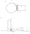
- Figure 1 shows a first embodiment of a marine fender 1.
- the fender 1 is configured for engagement with a wind turbine monopile 10 during a transfer operation in which crew is transferred between a boat 5 and so-called secondary steel', such as external ladders and platforms, provided on the monopile's exterior.
- the fender 1 includes a frame 3 which is mounted at its rear to the bow of the boat 5.
- the front of the fender 1 comprises a roller 2 which forms an engagement part used to engage with the opposing surface 11 of the monopile 10.
- the roller has a rubberised outer surface which forms a high friction interface when pressed against the monopile.
- the roller 2 is held in a horizontal orientation and is connected to the frame 3 by a rotatable coupling 4.
- the coupling 4 comprises a horizontal axel which extends through the roller 2 and a rotary damper which restrains rotation of the roller about the axel.
- the rotary damper is a viscous rotary damper, whereby rotation is resisted by the shearing of viscous fluid within the damper body. This thereby controls the speed of rotation of the roller 2.
- other damper mechanisms may be used, such as spring dampers or computer regulated dampers.
- the resistance profile of the damper may be controlled, for example based on feedback from force sensor and/or a wave prediction system. This may allow the speed of rotation of the roller 2 to be varied throughout its movement to optimise the velocity control provided by the fender.
- the boat 5 and monopile 10 are forced together, for example by driving the boat 5 toward the monopile 10, such that roller 2 is forced into engagement with the opposing surface 11 of the monopile body 10.
- other mechanisms may be used to force the vessel and structure together, such as a magnetic arrangement which draws the surfaces together.
- the engagement force establishes static friction at the interface between the surface area of the roller 2 in contact with the monopile 10.
- the restraining action of the rotary damper resists rotation of the roller 2 such that it is not free to roll vertically up or down the opposing surface 11.
- the boat 5 is effectively pinned at its bow to the exterior of the monopile 10 through the fender 1, with the forward drive force of the boat's propeller pressing the interface surfaces together.
- the fender 1 may be pinned to the opposing surface 11 in a relatively high position.
- wave troughs will cause the water level to move downward relative to the position of the boat 5.
- the rotational damper provided in coupling 4 is configured to permit the roller 2 to roll down the monopile 10 in a controlled manner.
- the boat 5 transitions slowly to a lower position, as shown in Figure 2 , with some of the potential energy from the vertical transition being dissipated through the rotary damper.
- the risk of uncontrolled slippage between the fender 1 and the monopile 10 is mitigated.
- rapid changes in the vertical position of the boat's bow may be avoided by damping movements caused by passing waves through the regulated movement of the roller 2.
- This thereby extends the time periods during which safe transfer of crew and other bodies between the boat 5 and monopile 10 may be achieved.
- the horizontal roller 2 in this embodiment acts to regulate vertical movement, it will be understood that lateral and rotational forces applied through the interface are also resisted.
- slippage of the fender across the opposing surface is minimised, wear and other mechanical damage which might otherwise occur to the structure or its secondary steel is minimised.
- the roller 2 may also be provided with a profile for more closely mating with the corresponding surface of the opposing structure.
- the roller 2 may have a concave cylinder profile for mating with the curvature of the monopile body.
- Figure 3 shows a schematic top view of a marine fender according to a second embodiment.
- This embodiment operates in substantially the same way as the first embodiment, except that a second roller 2b is provided.
- first and second rollers 2a,2b are supported in a V-configuration by the frame 3, to form a combined concave engagement area which can be wedged onto the curved opposing surface 11 of the monopile 10.
- the coupling 4 comprises two axels for supporting the rollers 2a,2b, with the axels connected to a central rotary damper 7 which regulates the rotational speed of both rollers 2a,2b for thereby resisting rapid changes in position of the boat 5 during the transfer operation.
- rollers 2a,2b in an angled configuration provides greater resistance to lateral forces applied to the boat 5, as well as a larger contact surface area for regulating vertical movements.
- more than two rollers may be provided.
- three rollers 2 may be used to further increase the frictional engagement with the foundation 10.
- FIG. 4 shows a schematic side view of a marine fender according to a third embodiment.
- This embodiment operates in a similar way to the first and second embodiments except that, rather than a roller, the engagement part is provided as an interface plate 2 which is moveably coupled to the mounting frame 3 by a coupling 4 comprising piston fluid viscous dampers.
- the coupling 4 allows the interface plate 2 to move vertically relative to the mounting frame 3 in a plane that is parallel to the vertical plane of the mounting.
- the interface plate 2 can resistively shear vertically relative to its mounting.
- the fender 1 effectively deforms in response to the forces applied to it. Consequently, upward or downward forces applied to the boat 5 are initially absorbed by the coupling 4, until it reaches the extremity of its moveable range.
- the periods where the boat 5 moves in an uncontrolled manner are reduced, thereby minimising the occurrences of rapid changes in the vertical position of the boat's bow. Accordingly, a safer method of transferring crew and other bodies between a boat and an offshore structure, such as a monopile, may thereby be provided.
- a wave detection system with an indicator may be used to alert crew members to periods where safe transfer from a vessel to a structure may be facilitated.
- arrangements according to the claimed invention may extend these time periods by resisting vessel movements when the vessel is subjected to smaller waves and slowing vessel movements when larger waves hit.
- the offshore structure may be provided with an adapted surface as the opposing surface for engagement by the engagement part.
- a high-friction coating may be provided to increase the interface friction with the engagement part.
- a controllable frictional interface between the engagement part and the opposing surface is provided. This may be achieved, for instance, by providing a fluid feed at the coupling for selectively lubricating the contact area between the engagement part and the opposing surface. This may be used independently with a fixed engagement plate or in combination with a mechanically moveable engagement part. In periods where the vertical transition between a wave crest and trough are larger, liquid may be applied to lubricate the interface for controlling the fender's movement across the surface of the structure. This may allow a consistent and predicable movement, rather than a sudden drop or rise. Conversely, in periods where the vertical transition between a wave crest and trough are smaller, friction may be increased by removing the lubricant, thereby providing a more stable position of the vessel.
- the fender may be configured for engagement with other parts of the offshore structure.
- the engagement part of the fender may be profiled for engagement with a boat landing or with secondary steel structures.
- embodiments of the invention are also applicable to transfer operations between a vessel and a floating offshore structure, such as a floating wind turbine or platform.
- both the vessel and the structure may move in the waves.
- the vessel and the structure can have, for instance, different weights, shapes, different centres of gravity, different buoyancies, and be influenced by wind differently, they may move differently in the water.
- embodiments of the invention may similarly be used to resist and regulate relative movements between the two engaged parts, thereby allowing safer object transfer operations between the vessel and the structure.
Landscapes
- Engineering & Computer Science (AREA)
- Mechanical Engineering (AREA)
- General Engineering & Computer Science (AREA)
- Chemical & Material Sciences (AREA)
- Combustion & Propulsion (AREA)
- Ocean & Marine Engineering (AREA)
- Civil Engineering (AREA)
- Structural Engineering (AREA)
- Transportation (AREA)
- Environmental & Geological Engineering (AREA)
- Vibration Prevention Devices (AREA)
Priority Applications (2)
| Application Number | Priority Date | Filing Date | Title |
|---|---|---|---|
| EP21215701.0A EP4197896B1 (de) | 2021-12-17 | 2021-12-17 | Schiffsfender und verfahren zur übertragung eines körpers zwischen einem schiff und einer offshore-struktur |
| US18/081,520 US20230192250A1 (en) | 2021-12-17 | 2022-12-14 | Marine fender and method for transferring a body between a vessel and an offshore structure |
Applications Claiming Priority (1)
| Application Number | Priority Date | Filing Date | Title |
|---|---|---|---|
| EP21215701.0A EP4197896B1 (de) | 2021-12-17 | 2021-12-17 | Schiffsfender und verfahren zur übertragung eines körpers zwischen einem schiff und einer offshore-struktur |
Publications (2)
| Publication Number | Publication Date |
|---|---|
| EP4197896A1 true EP4197896A1 (de) | 2023-06-21 |
| EP4197896B1 EP4197896B1 (de) | 2026-01-28 |
Family
ID=78957199
Family Applications (1)
| Application Number | Title | Priority Date | Filing Date |
|---|---|---|---|
| EP21215701.0A Active EP4197896B1 (de) | 2021-12-17 | 2021-12-17 | Schiffsfender und verfahren zur übertragung eines körpers zwischen einem schiff und einer offshore-struktur |
Country Status (2)
| Country | Link |
|---|---|
| US (1) | US20230192250A1 (de) |
| EP (1) | EP4197896B1 (de) |
Families Citing this family (1)
| Publication number | Priority date | Publication date | Assignee | Title |
|---|---|---|---|---|
| DE102024109773A1 (de) * | 2024-04-08 | 2025-10-09 | Hochschule Flensburg Körperschaft des öffentlichen Rechts | Boot-fender-anlege-vorrichtung und verwendung |
Citations (6)
| Publication number | Priority date | Publication date | Assignee | Title |
|---|---|---|---|---|
| DE8806733U1 (de) * | 1988-05-24 | 1988-07-21 | Kolb, Rudolf, 5590 Cochem | Fender |
| WO2011154730A2 (en) * | 2010-06-07 | 2011-12-15 | Bmt Nigel Gee Limited | Transfer apparatus for vessels |
| GB2483401A (en) * | 2009-11-05 | 2012-03-07 | David Armstrong | Pivoting deck vessel for allowing transfer to a fixed structure |
| GB2520094A (en) * | 2013-09-17 | 2015-05-13 | Alicat Workboats Ltd | Pole Engagement device for marine vessels |
| EP3647178A1 (de) * | 2018-10-29 | 2020-05-06 | Ørsted Wind Power A/S | Ein schiff mit einem bugfender |
| KR20210115676A (ko) * | 2020-03-16 | 2021-09-27 | 와이엠아이 주식회사 | 회전기능과 선박 손상을 방지할 수 있는 해상구조물 |
Family Cites Families (1)
| Publication number | Priority date | Publication date | Assignee | Title |
|---|---|---|---|---|
| US3585958A (en) * | 1969-05-05 | 1971-06-22 | North American Rockwell | Buffer system for ships |
-
2021
- 2021-12-17 EP EP21215701.0A patent/EP4197896B1/de active Active
-
2022
- 2022-12-14 US US18/081,520 patent/US20230192250A1/en active Pending
Patent Citations (6)
| Publication number | Priority date | Publication date | Assignee | Title |
|---|---|---|---|---|
| DE8806733U1 (de) * | 1988-05-24 | 1988-07-21 | Kolb, Rudolf, 5590 Cochem | Fender |
| GB2483401A (en) * | 2009-11-05 | 2012-03-07 | David Armstrong | Pivoting deck vessel for allowing transfer to a fixed structure |
| WO2011154730A2 (en) * | 2010-06-07 | 2011-12-15 | Bmt Nigel Gee Limited | Transfer apparatus for vessels |
| GB2520094A (en) * | 2013-09-17 | 2015-05-13 | Alicat Workboats Ltd | Pole Engagement device for marine vessels |
| EP3647178A1 (de) * | 2018-10-29 | 2020-05-06 | Ørsted Wind Power A/S | Ein schiff mit einem bugfender |
| KR20210115676A (ko) * | 2020-03-16 | 2021-09-27 | 와이엠아이 주식회사 | 회전기능과 선박 손상을 방지할 수 있는 해상구조물 |
Also Published As
| Publication number | Publication date |
|---|---|
| US20230192250A1 (en) | 2023-06-22 |
| EP4197896B1 (de) | 2026-01-28 |
Similar Documents
| Publication | Publication Date | Title |
|---|---|---|
| EP2520485B1 (de) | System und Verfahren zum Vertäuen eines schwimmenden Fahrzeugs an einem ortsfesten Objekt | |
| DE69917050T2 (de) | Festmachvorrichtung | |
| GB2473490A (en) | Progressive bow transfer apparatus and method | |
| US20230192250A1 (en) | Marine fender and method for transferring a body between a vessel and an offshore structure | |
| EP2487102A1 (de) | Zugangsvorrichtung zum Umladen von Schiffen auf feste Strukturen | |
| WO2021130133A1 (en) | A feeder vessel | |
| CN110761172A (zh) | 一种伸缩式栈桥系统及其控制方法 | |
| WO2013174886A1 (en) | Vessel gangway system | |
| US4544137A (en) | Offshore crane wave motion compensation apparatus | |
| WO2016192719A1 (de) | Verfahren zum anlanden eines wasserfahrzeugs an einem bauwerk | |
| CN112829879B (zh) | 一种抱桩登塔系统 | |
| CN210827339U (zh) | 一种提供全向回复力的系泊装置 | |
| CN114562497B (zh) | 一种用于防坠落装置的液压自适应控制系统及其控制方法 | |
| EP2829468A2 (de) | Marines Übertragungssystem | |
| DE102007011711A1 (de) | Verfahren zur Antizipation von Wellen- und Windbewegungen und zu deren Kompensation | |
| CN113213361B (zh) | 一种吊具防挂舱装置、方法及起重设备 | |
| CN119611650A (zh) | 适用于复杂海况条件的水面及水下装备布放回收方法及装置 | |
| US7996942B2 (en) | Rotating gangway support platform | |
| EP2151375A1 (de) | Systeme zum Umsetzen einer Person oder Ladung zwischen einem Schiff und einem Meeresbauwerk | |
| CN119553646B (zh) | 一种主动自适应船艏形状的升船机防撞装置及方法 | |
| EP3318477A1 (de) | Krängungsarmes segelboot | |
| AU2016223339B2 (en) | Device for handling and towing a submersible object | |
| Marsh | Deep offshore O&M: accessing all areas | |
| KR101626389B1 (ko) | 구명정의 자세유지 및 감속장치 | |
| GB2482370A (en) | Apparatus for controlling a suspended load or a moored vessel |
Legal Events
| Date | Code | Title | Description |
|---|---|---|---|
| PUAI | Public reference made under article 153(3) epc to a published international application that has entered the european phase |
Free format text: ORIGINAL CODE: 0009012 |
|
| STAA | Information on the status of an ep patent application or granted ep patent |
Free format text: STATUS: THE APPLICATION HAS BEEN PUBLISHED |
|
| AK | Designated contracting states |
Kind code of ref document: A1 Designated state(s): AL AT BE BG CH CY CZ DE DK EE ES FI FR GB GR HR HU IE IS IT LI LT LU LV MC MK MT NL NO PL PT RO RS SE SI SK SM TR |
|
| STAA | Information on the status of an ep patent application or granted ep patent |
Free format text: STATUS: REQUEST FOR EXAMINATION WAS MADE |
|
| 17P | Request for examination filed |
Effective date: 20231219 |
|
| RBV | Designated contracting states (corrected) |
Designated state(s): AL AT BE BG CH CY CZ DE DK EE ES FI FR GB GR HR HU IE IS IT LI LT LU LV MC MK MT NL NO PL PT RO RS SE SI SK SM TR |
|
| STAA | Information on the status of an ep patent application or granted ep patent |
Free format text: STATUS: EXAMINATION IS IN PROGRESS |
|
| 17Q | First examination report despatched |
Effective date: 20250303 |
|
| GRAP | Despatch of communication of intention to grant a patent |
Free format text: ORIGINAL CODE: EPIDOSNIGR1 |
|
| STAA | Information on the status of an ep patent application or granted ep patent |
Free format text: STATUS: GRANT OF PATENT IS INTENDED |
|
| RIC1 | Information provided on ipc code assigned before grant |
Ipc: B63B 27/14 20060101AFI20250925BHEP Ipc: B63B 27/30 20060101ALI20250925BHEP Ipc: B63B 59/02 20060101ALI20250925BHEP Ipc: B63B 17/00 20060101ALN20250925BHEP Ipc: E02B 3/26 20060101ALN20250925BHEP |
|
| INTG | Intention to grant announced |
Effective date: 20251014 |
|
| GRAS | Grant fee paid |
Free format text: ORIGINAL CODE: EPIDOSNIGR3 |
|
| GRAA | (expected) grant |
Free format text: ORIGINAL CODE: 0009210 |
|
| STAA | Information on the status of an ep patent application or granted ep patent |
Free format text: STATUS: THE PATENT HAS BEEN GRANTED |
|
| AK | Designated contracting states |
Kind code of ref document: B1 Designated state(s): AL AT BE BG CH CY CZ DE DK EE ES FI FR GB GR HR HU IE IS IT LI LT LU LV MC MK MT NL NO PL PT RO RS SE SI SK SM TR |
|
| REG | Reference to a national code |
Ref country code: CH Ref legal event code: F10 Free format text: ST27 STATUS EVENT CODE: U-0-0-F10-F00 (AS PROVIDED BY THE NATIONAL OFFICE) Effective date: 20260128 Ref country code: GB Ref legal event code: FG4D |
|
| REG | Reference to a national code |
Ref country code: DE Ref legal event code: R096 Ref document number: 602021046734 Country of ref document: DE |
|
| REG | Reference to a national code |
Ref country code: IE Ref legal event code: FG4D |