EP4197911B1 - Appareil d'extension de siège, élément de division de cabine et cabine d'aéronef - Google Patents
Appareil d'extension de siège, élément de division de cabine et cabine d'aéronef Download PDFInfo
- Publication number
- EP4197911B1 EP4197911B1 EP23156261.2A EP23156261A EP4197911B1 EP 4197911 B1 EP4197911 B1 EP 4197911B1 EP 23156261 A EP23156261 A EP 23156261A EP 4197911 B1 EP4197911 B1 EP 4197911B1
- Authority
- EP
- European Patent Office
- Prior art keywords
- extension device
- seat
- extension
- cabin
- extension apparatus
- Prior art date
- Legal status (The legal status is an assumption and is not a legal conclusion. Google has not performed a legal analysis and makes no representation as to the accuracy of the status listed.)
- Active
Links
Images






Classifications
-
- B—PERFORMING OPERATIONS; TRANSPORTING
- B64—AIRCRAFT; AVIATION; COSMONAUTICS
- B64D—EQUIPMENT FOR FITTING IN OR TO AIRCRAFT; FLIGHT SUITS; PARACHUTES; ARRANGEMENT OR MOUNTING OF POWER PLANTS OR PROPULSION TRANSMISSIONS IN AIRCRAFT
- B64D11/00—Passenger or crew accommodation; Flight-deck installations not otherwise provided for
- B64D11/06—Arrangements of seats, or adaptations or details specially adapted for aircraft seats
- B64D11/0602—Seat modules, i.e. seat systems including furniture separate from the seat itself
- B64D11/0604—Seat modules, i.e. seat systems including furniture separate from the seat itself including a bed, e.g. cocoon type passenger seat modules
-
- B—PERFORMING OPERATIONS; TRANSPORTING
- B64—AIRCRAFT; AVIATION; COSMONAUTICS
- B64D—EQUIPMENT FOR FITTING IN OR TO AIRCRAFT; FLIGHT SUITS; PARACHUTES; ARRANGEMENT OR MOUNTING OF POWER PLANTS OR PROPULSION TRANSMISSIONS IN AIRCRAFT
- B64D11/00—Passenger or crew accommodation; Flight-deck installations not otherwise provided for
- B64D11/0023—Movable or removable cabin dividers, e.g. for class separation
-
- B—PERFORMING OPERATIONS; TRANSPORTING
- B64—AIRCRAFT; AVIATION; COSMONAUTICS
- B64D—EQUIPMENT FOR FITTING IN OR TO AIRCRAFT; FLIGHT SUITS; PARACHUTES; ARRANGEMENT OR MOUNTING OF POWER PLANTS OR PROPULSION TRANSMISSIONS IN AIRCRAFT
- B64D11/00—Passenger or crew accommodation; Flight-deck installations not otherwise provided for
- B64D11/06—Arrangements of seats, or adaptations or details specially adapted for aircraft seats
- B64D11/0698—Seats suspended from aircraft walls
Definitions
- Seating arrangements in passenger vehicles such as aircraft often have limited space. Moreover, such seating arrangements are often configured such that the passenger is in a substantially upright or a slightly reclined position (e.g., a seated position). However, sitting upright for long periods of time can cause strain and is undesirable, such as on long flights.
- US 3 898 704 A discloses convertible seat-bed equipment for converting a reclining seat into an upper and lower bunk bed in an aircraft cabin. From seat position the bottom and back pivot up and legs pivotally mounted on the back drop down to support the horizontally extended bottom and back to comprise the top bunk. A fastener on the bottom attaches to the adjacent wall.
- the bottom bunk comprises pivotally mounted sections which extend with one end resting on a cross-member on the legs of the upper bunk. The midsection is supported and secured on wall-mounted brackets which were used to support and secure the bottom of the seat when the seat position is used.
- US 2005/040288 A1 discloses an aircraft medical unit which comprises a front panel configured to fit in an aircraft cabin so as to form a divider inside the cabin and a spaced rear panel of substantially the same shape as that of the front panel.
- a side panel is constructed between the front and rear panels, and the front, rear and side panels defines a chamber.
- An access opening is formed in the front panel.
- a stretcher frame is provided and is movable between a folded and stowed position in the chamber and an unfolded and extended position to the outside of the chamber.
- the aircraft medical unit further includes at least one item of medical equipment used in the treatment of a patient.
- US 2005/087650 A1 discloses a booth-type seating arrangement with fore and aft seats for airplanes and aircraft.
- a cabinet with a stowable video monitor and pull-up table can be positioned between the seats.
- Sliding gates integrated into the aisle seat end base can be deployed to form an enclosed play area for children.
- Theater-style seat bottoms can be provided which flip-up to provide more floor space.
- Child booster seats can be built into the seatbacks.
- the seatback and bottom cushions can articulate and slide within fixed frame members to combine with opposite cushions to form a flat sleeping configuration for passengers.
- US 2018/057169 A1 discloses a stowable reversible seat for a vehicle which includes a first member pivotally coupled to a floor for supporting a seat base, a second member releasably secured to the floor for supporting the seat base, and a seat back pivotally coupled to the first member. Components of the seat pivot between a folded configuration for stowing and a deployed configuration for seating. The orientation of the seat may be reversed for switching between a forward-facing direction and an aft-facing direction.
- a method of configuring a seat into an aircraft includes adapting a cabinet area to receive and conceal the seat, configuring a rail to make the seat slidable out from the cabinet area into an aisle, attaching a pivotable seat base on the seat, and pivotally mounting a supporting leg underneath a portion of the seat to secure the pivotable seat base in a substantially horizontal position.
- said seat extension apparatus is configured for a cabin dividing element, such as a bulkhead.
- the seat extension apparatus is also configured to provide an improved, stable and wide lay-flat bed surface to the passenger.
- the seat extension apparatus can be fixed to any type of cabin dividing element, such as a bulkhead or any other cabin interior and furniture element.
- the object of the seat extension apparatus is solved by the features claimed in claim 1.
- the object of the cabin dividing element is solved by the features claimed in claim 12.
- the extension device is movable between a vertical stowed position in which the mounting side is facing into the aircraft cabin and the bed surface side is in alignment with the cabin dividing element, and a horizontal use position in which the bed surface side is in alignment with a seat surface of the passenger seating arrangement and the mounting side is arranged on a bottom of the bed surface side.
- the seat extension apparatus comprises a support structure coupled to the extension device to pivotably support the extension device, wherein the support structure comprises at least one pivotable strut element having at least one end pivotably coupled to the mounting side of the extension device and at least one free end.
- the strut element In the vertical stowed position of the extension device the strut element is arranged substantially parallel to a longitudinal axis of the extension device, and in the horizontal use position of the extension device the strut element is arranged substantially perpendicular or angled to the longitudinal axis of the extension device.
- the mounting side In the vertical stowed position, the mounting side is facing into the aircraft cabin. For example, the mounting side is facing in a direction toward a passenger seat.
- the bed surface side is arranged on an opposite side of the mounting side.
- the bed surface side and the mounting side are arranged extending parallel to each other.
- the mounting side In the horizontal use position, the mounting side is arranged on a bottom of the bed surface side.
- the mounting side may be arranged facing in a direction toward a cabin floor.
- the bed surface side may be arranged facing in a direction toward a cabin ceiling.
- the extension device is configured as a bulkhead economy bed.
- the extension device may be configured as a substantially panel-shaped shelf element.
- the extension device may be configured as an ottoman.
- the bed surface side of the extension device may be cushioned providing more comfort to a passenger when the extension device is moved to the horizontal use position. In this position, the bed surface side may be arranged in a cabin space. That means that the bed surface side of the extension device may be visible and so as usable for the passenger as body support element.
- the strut element may be constructed to stably support the extension device in the horizontal use position, such as a wide lie-flat bed position, on a cabin floor.
- the second free end may be configured to be positioned on the cabin floor in a slip-resistant manner.
- the bed surface side may be substantially hidden from view of the passenger.
- the mounting side of the extension device is visible to the passenger.
- the mounting side may comprise an optically appealing finish, such as a layer, a cover, a coating or the like which fits to a design of the aircraft cabin.
- the mounting side may be provided with any surface material, a placard and/or a logo design.
- the seat extension apparatus is fixed to a cabin dividing element, such as a bulkhead, positioned in front of a passenger seating arrangement, such as a single seat or a row of at least two seats adjacent to each other in transverse direction of the cabin.
- the cabin dividing element may be a shell-like or wall-like element, such as a bulkhead, which for example divides aircraft cabin classes.
- the cabin dividing element may be arranged between a cabin seating arrangement and a galley or between a cabin seating arrangement and a doorway of the aircraft.
- the extension device can be moved, for example fold down in a pivot motion away from the cabin dividing element, into the horizontal use position.
- the bed surface side and a seat cushion create one continuously lay-flat bed surface to the passenger.
- the mounting side of the extension device comprises at least one carrier device to which the strut element is pivotably coupled.
- the carrier device may be arranged on side of the mounting side.
- the carrier device may be attached to the mounting side by a firm bond, force-fit and/or form-fit connection.
- the carrier device and the extension device may be configured as one-piece element.
- the extension device and the carrier device may be a molded, such as injection-molded part.
- the carrier device comprises at least one recess into which the strut element is fully arranged when the extension device is in the vertical stowed position.
- the extension device comprises an integrated carrier device with a recess.
- the extension device and the carrier device may be configured as one-piece component.
- the carrier device comprises at least one storage pocket.
- the storage pocket can be used to stow private items of the passenger and/or items provided by airline, such as magazines, a headphone or the like.
- the carrier device may be configured as a substantially box-shaped support element.
- the strut element is substantially U-shaped.
- free ends of legs of the U-shaped strut element may be connected to the extension device.
- the storage pocket may be formed between the legs of the U-shaped strut element.
- a connecting portion of the legs of the U-shaped strut element may be configured to be positioned on the cabin floor to sturdy support the extension device in the horizontal use position.
- the support structure comprises at least one support linkage configured to pivotably couple the extension device to the support structure.
- the support linkage is coupled to each one of the extension device and the support structure via a pivot point.
- a pivot point of the strut element and the pivot point of the support linkage are substantially arranged on the same pivot axis.
- the pivot axis is arranged in a center area of the extension device and perpendicular to the longitudinal axis of the extension device.
- the strut element when the extension device is pivoted from the vertical stowed position to the horizontal use position, the strut element is pivoted such that the strut element is fully arranged outside the recess of the carrier device.
- a rear side of the extension device comprises at least one latch mechanism to latch the extension device in the horizontal use position.
- a cabin dividing element for an aircraft cabin is provided, in particular arranged in front of a passenger seating arrangement, the cabin dividing element comprising at least a wall surface and a seat extension apparatus as described above, wherein the seat extension apparatus is coupled to the wall surface.
- the support structure comprises at least a bracket fixedly connected to the wall surface or to a cabin floor to pivotably support the extension device relative to the wall surface.
- the wall surface comprises a latch element for the latch mechanism of the seat extension apparatus so that the extension device is latched to the wall surface in the horizontal use position.
- the wall surface comprises an attachment mechanism for at least one bassinet.
- parents can lie flat on the seat extension apparatus or sit on the passenger seating arrangement while their baby is safely located near to them.
- an aircraft cabin may comprise at least a passenger seating arrangement, and a cabin dividing element as described above, wherein the cabin dividing element may be arranged in front of the passenger seating arrangement.
- the passenger seating arrangement may comprise at least one pivotable armrest having at least one stowable tray table.
- a movable tray table is integrated inside the armrest.
- the armrest provides an in-arm tray table.
- the tray table may be moved out from the inside of the armrest to provide a surface panel to the passenger.
- the armrest may be movable between a retracted stowed position, in which the armrest is arranged substantially alongside a side surface of a backrest of the passenger seating arrangement, and a deployed use position, in which the armrest is arranged substantially parallel and above a seat cushion of the passenger seating arrangement.
- the extension device is positioned in the horizontal use position the bed surface side of the extension device is in alignment with a seat surface of the passenger seating arrangement.
- Figures 1A to 1F show in perspective views an example of a seat extension apparatus 1 and a conversion of the seat extension apparatus 1 from a vertical stowed position P1, as shown in figures 1A and 1B , to a horizontal use position P2, as shown in figures 1E and 1F .
- the figures 1A to 1F shows an aircraft cabin C having a cabin dividing element 2, such as a bulkhead, and a passenger seating arrangement SA, wherein the seat extension apparatus 1 is fixed to the cabin dividing element 2.
- the passenger seating arrangement SA is arranged behind the cabin dividing element 2 and, for example, facing in flight direction of an aircraft.
- the seat extension apparatus 1 and the cabin dividing element 2 provide an improved bed feature within the aircraft cabin C.
- the seat extension apparatus 1 comprises an extension device 3 having a mounting side 3.1 and a bed surface side 3.2.
- the extension device 3 is movable between the vertical stowed position P1 and the horizontal use position P2.
- the seat extension apparatus 1 comprises a support structure 4 coupled to the extension device 3 to pivotably support the extension device 3 on the cabin dividing element 2.
- the support structure 4 comprises a pivotable strut element 5 having a first end 5.1 pivotably coupled to the mounting side 3.1 of the extension device 3 and a second free end 5.2.
- the strut element 5 is U-shaped. For example, free ends 5.2 of the two legs 5.3 of the U-shaped strut element 5 are connected to the extension device 3.
- a connecting portion 5.4 of the legs 5.3 of the U-shaped strut element 5 is configured to be positioned on a cabin floor F to sturdy support the extension device 3 in the horizontal use position P2.
- the strut element 5 being U-shaped provides a simple synchronized movement of the legs 5.3.
- the strut element 5 may be substantially O-shaped.
- the first ends 5.1 may be coupled together by a second connecting portion which is pivotably coupled to the mounting side 3.1.
- the strut element 5 may comprise two separate legs 5.3 arranged parallel to each other, wherein the free end 5.2 of each leg 5.3 is positioned on the cabin floor F in the horizontal use position P2 of the extension device 3.
- Each leg 5.3 may be substantially I-shaped.
- the strut element 5 may be springloaded for a damped motion.
- the strut element 5 In the vertical stowed position P1 the strut element 5 is arranged substantially parallel to a longitudinal axis a of the extension device 3. In the horizontal use position P2 of the extension device 3 the strut element 5 is arranged substantially perpendicular or angled to the longitudinal axis a of the extension device 3.
- the bed surface side 3.2 is cushioned providing more comfort to a passenger O when the extension device 3 is positioned in the horizontal use position P2. In this position, the bed surface side 3.2 is visible and so as usable for the passenger O as body support element.
- the strut element 5 is constructed to stably support the extension device 3 in the horizontal use position P2, such as a wide lie-flat bed position, on the cabin floor F.
- the second free end 5.2 is configured to be positioned on the cabin floor F.
- the bed surface side 3.2 is substantially hidden from view of the passenger O.
- the mounting side 3.1 is visible to the passenger O.
- the mounting side 3.1 comprises an optically appealing finish, such as a layer, a cover, a coating or the like which fits to a design of the aircraft cabin C.
- the mounting side 3.1 may comprise a storage pocket 6, a mobile device holder or the like.
- the storage pocket 6 comprises a holding belt or strap 6.1 configured to secure items arranged inside the storage pocket 6.
- the mounting side 3.1 comprises a carrier device 7 to which the strut element 5 is pivotably coupled to.
- the carrier device 7 comprises a recess 7.1 corresponding with the shape, for example U-shape, O-shape or I-shape, of the strut element 5.
- the strut element 5 is fully arranged in the recess 7.1 when the extension device 3 is positioned in the vertical stowed position P1.
- the carrier device 7 may comprise the storage pocket 6.
- the storage pocket 6 is arranged between the legs 5.3 of the strut element 5.
- the support structure 4 comprises a support linkage 8 configured to pivotably couple the extension device 3 to the support structure 4.
- the support structure 4 comprises at least a bracket 9 fixedly connected to a wall surface 2.1 of the cabin dividing element 2 to pivotably support the extension device 3 relative to the wall surface 2.1.
- the support structure 4 comprises two parallel aligned and spaced-apart brackets 9.
- the brackets 9 are fixed to a bottom side of the wall surface 2.1.
- the brackets 9 may be fixed to the cabin floor F.
- the support structure 4 comprises two parallel aligned and spaced-apart support linkages 8.
- Each of the support linkages 8 is pivotably hold in one of the brackets 9 and coupled to the extension device 3.
- the wall surface 2.1 may comprise at least one no further shown cavity in which the extension device 3 may be arranged. When the extension device 3 is stowed, the extension device 3 and the wall surface 2.1 may provide a substantially flat vertical surface.
- the support linkage 8 is coupled to each one of the extension device 3 and the support structure 4 via a pivot point PP1, PP2.
- Each lower pivot point PP1 is provided in the brackets 9.
- Each upper pivot point PP2 is provided on the mounting side 3.1 of the extension device 3.
- the upper pivot points PP2 are provided by the carrier device 7.
- Pivot points PP3 of the strut element 5 and each pivot point PP2 of the support linkages 8 are substantially arranged on the same pivot axis PA provided through the carrier device 7.
- the pivot axis PA is arranged in a center area of the extension device 3.
- the pivot axis PA is arranged perpendicular to the longitudinal axis a of the extension device 3. It is also possible to provide the pivot axis PA in a rear area or a front area of the extension device 3. The rear area is an area facing toward the wall surface and the front area is an area facing toward the passenger seating arrangement SA.
- the strut element 5 When the extension device 3 is pivoted from the vertical stowed position P1 to the horizontal use position P2, the strut element 5 is pivoted such that the strut element 5 is fully arranged outside the recess 7.1 of the carrier device 7. For example, the strut element 5 deploys by the rotation of the extension device 3.
- the strut element 5 may be coupled to the extension device 3 via a not further shown gear mechanism.
- a front side 3.3 of the extension device 3 comprises a flap 3.4 configured to be pulled by the passenger O to initiate movement, in particular rotation, of the extension device 3.
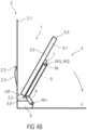
- a rear side 3.5 of the extension device 3 comprises a latch mechanism LM to latch the extension device 3 in the horizontal use position P2, as shown in figure 4D in more detail.
- the wall surface 2.1 comprises a latch element 2.2 as shown in figures 4A to 4D in more detail.
- the latch element 2.2 is one of a bar-like, ring, eyelet or loop element.
- the latch mechanism LM of the extension device 3 comprises a hook-like element 3.6, such as a claw latch, which is configured to detachably engage the latch element 2.2 arranged on the wall surface 2.1.
- the wall surface 2.1 comprises a cavity 2.3 in which the latch element 2.2 is arranged. It is also possible to provide the seat extension apparatus 1 with at least one motorized adjustment device which is configured to move the extension device 3 between the horizontal use position P2 and the vertical stowed position P1 automatically upon actuation e.g. via a remote control.
- the seat extension apparatus 1 comprises three extension devices 3 and corresponding supporting parts as described above.
- the extension devices 3 are arranged in a row, adjacent to each other in transverse direction of the aircraft cabin C.
- the passenger seating arrangement SA comprises therefore three single seats 10 arranged adjacent to each other in transverse direction of the aircraft cabin C.
- Each seat 10 comprises at least a seat cushion 10.1 and a backrest 10.2.
- Each seat 10 corresponds to one extension device 3 arranged in the front.
- Each passenger O of each seat 10 can use the respective extension device 3 as seat extension.
- the front side 3.3 of the extension device 3 contacts the seat cushion 10.1 such that the bed surface side 3.2 of the extension device 3 and the seat cushion 10.1 together form the seat extension, such as a bed extension.
- the passenger seating arrangement SA comprises a number of pivotable armrests 11, 11' arranged between two seats 10.
- the arrangement may comprise four armrests 11 to 11".
- outer side armrests 11" are fixed to outer sides of outer seats 10 facing in a direction e.g. toward a cabin aisle.
- the outer side armrests 11" may be pivotable or non-pivotable.
- Each armrest 11 and 11" having a stowable tray table 12.
- only one pivotable armrest 11 with a stowable tray table 12 arranged inside the pivotable armrest 11 is enough.
- the pivotable armrest 11 provides the tray table 12 for a center seat 10 arranged between two outer seats 10.
- the outer seats 10 will be given an additional reference sign 10'.
- the center seat 10 will be given an additional reference sign 10".
- each of the pivotable armrests 11, 11' is arranged between two adjacent seats 10.
- the tray table 12 is vertically stowed and the armrest 11 is in the deployed use position P3, as shown in figure 1A , the deployed armrest 11 can be used as a seating area dividing element.
- the armrests 11, 11' are movable between a retracted stowed position P4, as exemplarily shown in figure 1B , in which the armrests 11 are arranged substantially alongside a side surface of the backrests 10.2, and the deployed use position P3, in which the armrests 11 are arranged substantially parallel and above the seat cushions 10.1.
- each armrest 11 is locked.
- a commonly known release button connected to a lock mechanism of the armrest 11 may be provided on the armrest 11 and pushed.
- the passenger seating arrangement SA in particular all seats 10, turn into a divan bed.
- seat cushion surfaces of each seat cushion 10.1 are in contact with each other such that the seat cushion surfaces form a unitary sitting (bench-like) and bed surface along the passenger seating arrangement SA.
- Figure 2 shows a perspective view of an embodiment of a converted seat extension apparatus 1 creating a wide lie-flat bed surface with the passenger seating arrangement SA.
- this wide lie-flat bed surface may be used by one single passenger O or by more than one passenger O on each corresponding seat 10.
- Figure 3 shows a perspective view of an embodiment of a cabin dividing element 2 comprising an attachment mechanism AM, as shown in figure 2 , for a bassinet 13.
- the wall surface 2.1 comprises the attachment mechanism AM for the bassinet 13.
- Figures 4A to 4D schematically show the seat extension apparatus 1 and a conversion of the seat extension apparatus 1 from a vertical stowed position P1 to a horizontal use position P2.
- figure 4A shows the extension device 3 in the vertical stowed position P1
- figure 4B shows the extension device 3 in a slightly pivoted forward position from the stowed position P1 in a direction to the horizontal use position P2
- figure 4C shows the extension device 3 in a pivoted position close to the horizontal use position P2
- figure 4D shows the extension device 3 in the horizontal use position P2.
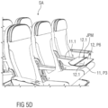
- Figures 5A to 5E show in perspective views an embodiment of a passenger seating arrangement SA comprising at least one pivotable armrest 11 having a stowable tray table 12.
- the tray table 12 is configured as a bi-fold table.
- the armrest 11 comprises a slot 11.1, for example in form of a through hole, through which the tray table 12 can be moved in a bi-folded state.
- the tray table 12 is configured as a single shelf.
- figure 5A shows each of the armrests 11 and 11' arranged above and substantially parallel to the seat cushion 10.1, each armrest 11 and 11' being positioned in the deployed use position P3, wherein a tray table 12 is arranged within the armrest 11 and is stowed inside the armrest 11, the tray table 12 being arranged in a vertical position P5.
- Figure 5B shows the armrest 11 with an open lid 11.3 and a tray table 12 which is moved out from the inside of the armrest 11
- figures 5C and 5D show the armrest 11 with the tray table 12 in a horizontal position P6
- figure 5E shows the armrests 11 and 11' in the retracted stowed position P4.
- Figure 5F shows an enlarged section of the seating arrangement SA according to figure 5B .
- the seating arrangement SA comprises three seats 10, two outer side seats 10' and one center seat 10" arranged between the outer side seats 10'.
- the seating arrangement SA further comprises four armrests 11 to 11", two outer side armrests 11" and two inner side armrests 11 and 11'.
- Each of the inner side armrests 11 and 11' is arranged between one of the outer side seats 10' and the center seat 10". Therefore, each seat 10, 10' to 10" comprises two armrests 11 to 11" which may be used.
- the outer side armrests 11" comprise stowable tray tables 12 for passengers of the outer side seats 10'.
- One of the inner side armrests 11 comprises a tray table 12 for a passenger of the center seat 10".
- pivotable armrests 11 In an arrangement of two seats 10, it is possible to provide pivotable armrests 11 with tray tables 12 on outer sides of the seats 10. Between the two seats 10 one pivotable armrest without a tray table 12 may be arranged.
- the armrest 11 is pivotable mounted to a backrest 10.2, such as a backrest 10.2 frame structure.
- the tray table 12 is configured as a bi-fold table; for example the tray table 12 comprises two tabletops 12.1 which are hinged to each other such that the two tabletops 12.1 can be folded one above the other.
- the armrest 11 comprises the slot 11.1 in which the tray table 12 may be fully stowed when not needed.
- the armrest 11 comprises a casing 11.2 which corresponds to the tray table 12 in its bi-folded shape.
- the casing 11.2 comprises an attachment section 11.2.1 which is pivotable mounted to the seat 10, for example to the center seat 10" and/or to the corresponding outer side seat 10'.
- the casing 11.2 further comprises a main section 11.2.2 for the passenger.
- the lid 11.3, the tray table 12 and the joint and pivot mechanism JPM are arranged being easy to reach for the passenger.
- the casing 11.2 is configured such that dimensions of the main section 11.2.2 are larger than dimensions of the attachment section 11.2.1.
- the armrest 11 comprises the lid 11.3 which is hinged on the area of the slot 11.1 to cover up the slot 11.1.
- the lid 11.3 is arranged on an upper surface side of the armrest 11.
- the lid 11.3 is arranged on the upper surface side of the casing 11.2.
- the joint and pivot mechanism JPM may be arranged outside the slot 11.1 and a lid covering area.
- the joint and pivot mechanism JPM is arranged on the upper surface side of the armrest 11, for example of the casing 11.2.
- figure 5A shows the tray table 12 in a stowed state within the armrest 11.
- Figure 5B shows the tray table 12 in a vertically deployed and upward directed state.
- Figure 5C shows the tray table 12 in a folded down horizontal state.
- Figure 5D shows the tray table 12 in a flipped opened state, wherein the tabletops 12.1 form a wider table surface.
- Figure 5E shows the armrest 11 in a retracted stowed position P4, wherein the tray table 12 is stowed within the armrest casing 11.2.
- armrests 11 of the outer seats 10' each comprise a stowable tray table 12.
- a second center armrest 11' may be configured as a common pivotable armrest 11'.
- the passenger seating arrangement SA comprises an armrest apparatus 11A comprising a tray table apparatus 12A.
- the armrest apparatus 11A comprises the casing 11.2 configured to receive and retain the tray table apparatus 12A.
- the tray table apparatus 12A comprises the tray table 12 and the joint and pivot mechanism JPM.
- the joint and pivot mechanism JPM is configured to connect the tray table apparatus 12A to the armrest apparatus 11A.
- the armrest apparatus 11A comprises the main section 11.2.2 and the attachment section 11.2.1.
- the casing 11.2 of the armrest apparatus 11A comprises the slot 11.1 to receive the tray table apparatus 12A.
- the tray table apparatus 12A is arranged in the main section 11.2.2 of the armrest apparatus 11A.
- the slot 11.1 is configured as a vertical recess provided in the casing 11.2. In the stowed vertical position P5 of the tray table apparatus 12A, the tray table 12 of the tray table apparatus 12A is fully arranged inside the slot 11.1 so as inside the casing 11.2 protected from external influences.
- the slot 11.1 is open at a top of the casing 11.2 facing in a direction toward the cabin ceiling.
- the armrest apparatus 11A further comprises the lid 11.3. One side of the lid 11.3 is hinged to the casing 11.2 in the area of the slot 11.1.
- the casing 11.2 comprises a latch element 11.4 arranged in the area of the slot 11.1 on an opposite side of a hinge 11.5 of the lid 11.3.
- the latch element 11.4 may comprise a clip-function, snap-function or any other engagement function to secure the lid 11.3 in a closed position to the casing 11.2.
- the joint and pivot mechanism JPM is arranged outside of the lid covering area.
- the joint and pivot mechanism JPM may be arranged in the slot 11.1 in an area which is not covered by the lid 11.3.
- the joint and pivot mechanism JPM comprises a first hinge element 14.
- the first hinge element 14 is pivotable coupled to armrest apparatus 11A, for example the casing 11.2.
- the first hinge element 14 is pivotable about a first pivot axis PA1 extending parallel to a transverse axis y of the cabin C.
- the joint and pivot mechanism JPM comprises a second hinge element 15.
- the second hinge element 15 is pivotable about a second pivot axis PA2 extending parallel to a longitudinal axis x of the cabin C.
- the pivot axes PA1 and PA2 are extending substantially perpendicular to each other.
- the second hinge element 15 is pivotable coupled to the first hinge element 14. Further, the second hinge element 15 couples the tray table 12 to the first hinge element 14.
- the first hinge element 14 is, for example, substantially U-shaped.
- the second hinge element 15 is arranged between legs 14.1 of the first hinge element 14. A connection region of the legs 14.1 is pivotable coupled to the casing 11.2.
- the tray table 12 Via the first pivot axis PA1, the tray table 12 is movable from the slot 11.1.
- the tray table 12 is pivotable between the stowed vertical position P5 and the intermediate deployed position P7.
- the tray table 12 is movable toward the seat cushion 10.1.
- the tray table 12 is pivotable between the intermediate deployed position P7 and the horizontal position P6.
- the tray table apparatus 12A further comprises a table support 12.2.
- the table support 12.2 is configured as a bracket or holder element to movably support the tray table 12.
- the tray table 12 is attached to the table support 12.2.
- one of the two tabletops 12.1 is attached to the table support 12.2.
- the tray table 12 comprises a pull-out flap 12.3.
- the pull-out flap 12.3 is arranged in an area of a hinge connection of the two tabletops 12.1.
- the pull-out flap 12.3 allows a simple operation to move the tray table 12 out from the slot 11.1, i.e. from the stowed vertical position P5 to the intermediate deployed position P7.
- outer side armrests 11" also may be configured from an armrest apparatus 11A comprising a tray table apparatus 12A as described above.
- Figure 6 shows a flow chart of a method of deploying a seat extension apparatus 1, wherein the method comprises at least two steps S1 and S2.
- the seat extension apparatus 1 is coupled to a cabin dividing element 2.
- the seat extension apparatus 1 comprises an extension device 3 having a mounting side 3.1 and a bed surface side 3.2.
- the extension device 3 is movable between a vertical stowed position P1 and a horizontal use position P2.
- the seat extension apparatus 1 comprises a support structure 4 coupled to the extension device 3 to pivotably support the extension device 3 on the cabin dividing element 2.
- the support structure 4 comprises a pivotable strut element 5 having at least one end 5.1 pivotably coupled to the mounting side 3.1 of the extension device 3 and at least one free end 5.2 which, when located on a cabin floor F, supports the extension device 3 in the horizontal use position P2.
- a first step S1 comprises moving the extension device 3 from the vertical stowed position P1 in a direction toward the horizontal use position P2. That means that in the first step S1, the extension device 3 moves, e.g. pivots, from the vertical stowed position P1 in a direction away from the cabin dividing element 2.
- a second step S2 comprises pivoting the support structure 4 such that the strut element 5 moves from a substantially parallel orientation relative to the extension device 3 to a substantially perpendicular or angled orientation relative to the extension device 3. That means that in the second step S2, the strut element 5 pivots in a direction away from the cabin dividing element 2 toward the cabin floor F.
- a third step may comprise positioning at least one free end 5.2 of the strut element 5 on the cabin floor F and the extension device 3 in the horizontal use position P2. That means that when the strut element 5 stands on the cabin floor F, e.g. when the free end 5.2 reaches the cabin floor F, the extension device 3 is fully positioned in the horizontal use position P2.
- a not further shown step for example between the second step S2 and the third step or after the third step, may comprise latching the extension device 3 to the cabin dividing element 2.
Landscapes
- Engineering & Computer Science (AREA)
- Aviation & Aerospace Engineering (AREA)
- Seats For Vehicles (AREA)
- Health & Medical Sciences (AREA)
- Child & Adolescent Psychology (AREA)
- General Health & Medical Sciences (AREA)
Claims (15)
- Appareil d'extension de siège (1) pouvant être fixé à un élément de division de cabine (2) positionné devant une disposition de sièges passagers (SA) dans une cabine d'aéronef (C), l'appareil d'extension de siège (1) comprenant au moins :- un dispositif d'extension (3) ayant un côté de montage (3.1) et un côté de surface de lit (3.2), dans lequel le dispositif d'extension (3) peut se déplacer entre une position de rangement verticale (P1) dans laquelle le côté de montage (3.1) fait face à la cabine d'aéronef (C) et le côté de surface de lit (3.2) est en alignement avec l'élément de division de cabine (2), et une position d'utilisation horizontale (P2) dans laquelle le côté de surface de lit (3.2) est en alignement avec une surface de siège de l'arrangement de siège passager (SA) et le côté de montage (3.1) est disposé sur un fond du côté de surface de lit (3.2), et- une structure de support (4) accouplée au dispositif d'extension (3) afin de soutenir de manière pivotante le dispositif d'extension (3), dans lequel la structure de support (4) comprend au moins un élément d'entretoise (5) pivotant ayant au moins une extrémité (5.1) accouplée de manière pivotante au côté de montage (3.1) du dispositif d'extension (3) et au moins une extrémité libre (5.2), dans lequel- dans la position de rangement verticale (P1) du dispositif d'extension (3), l'élément d'entretoise (5) est disposé sensiblement parallèlement à un axe longitudinal (a) du dispositif d'extension (3), et- dans la position d'utilisation horizontale (P2) du dispositif d'extension (3), l'élément d'entretoise (5) est disposé sensiblement perpendiculairement ou incliné par rapport à l'axe longitudinal (a) du dispositif d'extension (3).
- Appareil d'extension de siège (1) selon la revendication 1, dans lequel le côté de montage (3.1) du dispositif d'extension (3) comprend au moins un dispositif porteur (7) auquel l'élément d'entretoise (5) est accouplé de manière pivotante.
- Appareil d'extension de siège (1) selon la revendication 2, dans lequel le dispositif porteur (7) comprend au moins un évidement (7.1) dans lequel l'élément d'entretoise (5) est entièrement disposé lorsque le dispositif d'extension (3) est dans la position de rangement verticale (P1).
- Appareil d'extension de siège (1) selon la revendication 2 ou 3, dans lequel le dispositif porteur (7) comprend au moins une poche de rangement (6).
- Appareil d'extension de siège (1) selon l'une quelconque des revendications précédentes, dans lequel l'élément d'entretoise (5) est sensiblement en forme de U.
- Appareil d'extension de siège (1) selon l'une quelconque des revendications précédentes, dans lequel la structure de support (4) comprend au moins une liaison de support (8) conçue pour accoupler de manière pivotante le dispositif d'extension (3) à la structure de support (4).
- Appareil d'extension de siège (1) selon l'une quelconque des revendications 3 à 6, dans lequel la liaison de support (8) est accouplée à chacun du dispositif d'extension (3) et de la structure de support (4) par l'intermédiaire d'un point de pivotement (PP1, PP2).
- Appareil d'extension de siège (1) selon l'une quelconque des revendications précédentes, dans lequel un point de pivotement (PP3) de l'élément d'entretoise (5) et le point de pivotement (PP2) de la liaison de support (8) sont sensiblement disposés sur le même axe de pivotement (PA).
- Appareil d'extension de siège (1) selon la revendication 8, dans lequel l'axe de pivotement (PA) est disposé dans une zone centrale du dispositif d'extension (3) et perpendiculaire à l'axe longitudinal (a) du dispositif d'extension (3).
- Appareil d'extension de siège (1) selon l'une quelconque des revendications précédentes, dans lequel, lorsque le dispositif d'extension (3) pivote à partir de la position de rangement verticale (P1) vers la position d'utilisation horizontale (P2), l'élément d'entretoise (5) pivote de sorte que l'élément d'entretoise (5) est entièrement disposé à l'extérieur de l'évidement (7.1) du dispositif porteur (7).
- Appareil d'extension de siège (1) selon l'une quelconque des revendications précédentes, dans lequel un côté arrière (3.5) du dispositif d'extension (3) comprend au moins un mécanisme de verrouillage (LM) afin de verrouiller le dispositif d'extension (3) dans la position d'utilisation horizontale (P2).
- Élément de division de cabine (2) pour une cabine d'aéronef, conçu pour être disposé devant un arrangement de siège passager (SA), l'élément de division de cabine (2) comprenant au moins :- une surface de paroi (2.1) et- un appareil d'extension de siège (1) selon les revendications précédentes 1 à 11, dans lequel l'appareil d'extension de siège (1) est accouplé à la surface de paroi (2.1).
- Élément de division de cabine (2) selon la revendication 12, dans lequel la structure de support (4) comprend au moins un support (9) relié de manière fixe à la surface de paroi (2.1) ou à un plancher de cabine (F) afin de soutenir de manière pivotante le dispositif d'extension (3) par rapport à la surface de paroi (2.1).
- Élément de division de cabine (2) selon la revendication 12 ou 13, dans lequel la surface de paroi (2.1) comprend un élément de verrouillage (2.2) pour le mécanisme de verrouillage (LM) de l'appareil d'extension de siège (1) de sorte que le dispositif d'extension (3) est verrouillé à la surface de paroi (2.1) dans la position d'utilisation horizontale (P2).
- Élément de division de cabine (2) selon l'une quelconque des revendications 12 à 14, dans lequel la surface de paroi (2.1) comprend un mécanisme de fixation (AM) pour au moins un berceau (13).
Applications Claiming Priority (2)
| Application Number | Priority Date | Filing Date | Title |
|---|---|---|---|
| US201962925496P | 2019-10-24 | 2019-10-24 | |
| EP20203584.6A EP3812274B1 (fr) | 2019-10-24 | 2020-10-23 | Appareil d'extension de siège, élément de division de cabine et cabine d'aéronef |
Related Parent Applications (2)
| Application Number | Title | Priority Date | Filing Date |
|---|---|---|---|
| EP20203584.6A Division EP3812274B1 (fr) | 2019-10-24 | 2020-10-23 | Appareil d'extension de siège, élément de division de cabine et cabine d'aéronef |
| EP20203584.6A Division-Into EP3812274B1 (fr) | 2019-10-24 | 2020-10-23 | Appareil d'extension de siège, élément de division de cabine et cabine d'aéronef |
Publications (2)
| Publication Number | Publication Date |
|---|---|
| EP4197911A1 EP4197911A1 (fr) | 2023-06-21 |
| EP4197911B1 true EP4197911B1 (fr) | 2025-03-26 |
Family
ID=73014309
Family Applications (2)
| Application Number | Title | Priority Date | Filing Date |
|---|---|---|---|
| EP23156261.2A Active EP4197911B1 (fr) | 2019-10-24 | 2020-10-23 | Appareil d'extension de siège, élément de division de cabine et cabine d'aéronef |
| EP20203584.6A Active EP3812274B1 (fr) | 2019-10-24 | 2020-10-23 | Appareil d'extension de siège, élément de division de cabine et cabine d'aéronef |
Family Applications After (1)
| Application Number | Title | Priority Date | Filing Date |
|---|---|---|---|
| EP20203584.6A Active EP3812274B1 (fr) | 2019-10-24 | 2020-10-23 | Appareil d'extension de siège, élément de division de cabine et cabine d'aéronef |
Country Status (2)
| Country | Link |
|---|---|
| US (1) | US12065249B2 (fr) |
| EP (2) | EP4197911B1 (fr) |
Families Citing this family (4)
| Publication number | Priority date | Publication date | Assignee | Title |
|---|---|---|---|---|
| US20210339868A1 (en) * | 2020-04-30 | 2021-11-04 | Adient Aerospace, Llc | Passenger utility element and seat unit |
| DE102023101497B4 (de) * | 2023-01-23 | 2024-08-01 | Diehl Aviation Laupheim Gmbh | Am Flugbegleitersitz abgestützte Schlafliege |
| EP4434885A1 (fr) * | 2023-03-22 | 2024-09-25 | Safran Seats GB Limited | Berceau amélioré |
| US12304639B2 (en) | 2023-08-29 | 2025-05-20 | B/E Aerospace, Inc. | Contiguous passenger seat rows configured to form a bed |
Family Cites Families (16)
| Publication number | Priority date | Publication date | Assignee | Title |
|---|---|---|---|---|
| US2614613A (en) * | 1951-06-14 | 1952-10-21 | Helen W Bushong | Portable foldable leg rest |
| US2632408A (en) * | 1951-10-04 | 1953-03-24 | Giles Eugene Manning | Compartmentizable seat for railroad coaches and the like |
| US3264033A (en) * | 1965-04-08 | 1966-08-02 | George B Hansburg | Leg support |
| US3898704A (en) * | 1974-07-18 | 1975-08-12 | Mc Donnell Douglas Corp | Convertible seat-bed equipment |
| US5738306A (en) * | 1995-10-13 | 1998-04-14 | Air Methods Corporation | Articulating patient loading system and transport device for aircraft |
| DE10114837A1 (de) * | 2001-03-26 | 2002-10-10 | Fast Ag Grenchen | Armlehne |
| US6691952B2 (en) * | 2001-09-26 | 2004-02-17 | Marvin Keogh | Aircraft medical unit |
| US7108226B2 (en) * | 2003-10-10 | 2006-09-19 | The Boeing Company | Interior seating architecture for aircraft |
| GB0425323D0 (en) * | 2004-11-17 | 2004-12-22 | Britax Aircraft Interiors Uk L | Aircraft seat |
| GB2448835B (en) * | 2005-12-23 | 2010-12-29 | British Airways Plc | Aircraft passenger seat |
| US8960602B2 (en) * | 2008-02-27 | 2015-02-24 | Airbus Operations Gmbh | Partition wall in an aircraft |
| US20140084562A1 (en) * | 2012-09-27 | 2014-03-27 | Sunrise Medical (Us), Llc | Wheelchair transit bracket assembly |
| GB2526358B (en) * | 2014-05-23 | 2016-04-27 | Wan-yu li | Folding table and chair device |
| US10689120B2 (en) * | 2016-08-29 | 2020-06-23 | Textron Innovations, Inc. | Stowable reversible seat |
| US10059455B2 (en) * | 2016-10-26 | 2018-08-28 | Ami Industries, Inc. | Cabin attendant seat legrest with an extendable footrest |
| USD833161S1 (en) * | 2017-11-14 | 2018-11-13 | Christopher F. Haskell | Foldable leg support |
-
2020
- 2020-10-23 EP EP23156261.2A patent/EP4197911B1/fr active Active
- 2020-10-23 EP EP20203584.6A patent/EP3812274B1/fr active Active
- 2020-10-26 US US17/080,818 patent/US12065249B2/en active Active
Also Published As
| Publication number | Publication date |
|---|---|
| EP4197911A1 (fr) | 2023-06-21 |
| EP3812274B1 (fr) | 2023-03-22 |
| US20210122472A1 (en) | 2021-04-29 |
| EP3812274A1 (fr) | 2021-04-28 |
| US12065249B2 (en) | 2024-08-20 |
Similar Documents
| Publication | Publication Date | Title |
|---|---|---|
| EP4197911B1 (fr) | Appareil d'extension de siège, élément de division de cabine et cabine d'aéronef | |
| EP3653505B1 (fr) | Système de canapé inclinable pour siège de classe économique | |
| EP3704020B1 (fr) | Système de couchette inclinable pour siège de classe économique | |
| EP2635492B1 (fr) | Nacelle à lit coulissant | |
| CN102361795B (zh) | 与交通工具乘客座椅有关的改进 | |
| EP1817228B1 (fr) | Siege d'aeronef | |
| CN103596844B (zh) | 灵活使用的旅行套间 | |
| JP3990986B2 (ja) | 調節可能なシート | |
| US7311354B2 (en) | Seat for aircraft | |
| FI112638B (fi) | Istuinyksikkö | |
| RU2335417C2 (ru) | Трансформируемое кресло, предназначенное для размещения пассажира воздушного судна | |
| US8342450B2 (en) | Seating arrangement of a vehicle compartment | |
| CN102341306A (zh) | 座椅布置、座椅单元、托盘桌以及座椅系统 | |
| CN103857592A (zh) | 可转换为双层床的飞机沙发椅 | |
| CN110506004B (zh) | 具有舒适布局的乘客座椅 | |
| US8851568B2 (en) | Retractable passenger seat | |
| US11801941B2 (en) | Suite with improved arrangement, in particular for an aircraft cabin | |
| CN218999906U (zh) | 一种具有多姿态转换的座椅 | |
| GB2642361A (en) | A seat device |
Legal Events
| Date | Code | Title | Description |
|---|---|---|---|
| PUAI | Public reference made under article 153(3) epc to a published international application that has entered the european phase |
Free format text: ORIGINAL CODE: 0009012 |
|
| STAA | Information on the status of an ep patent application or granted ep patent |
Free format text: STATUS: THE APPLICATION HAS BEEN PUBLISHED |
|
| AC | Divisional application: reference to earlier application |
Ref document number: 3812274 Country of ref document: EP Kind code of ref document: P |
|
| AK | Designated contracting states |
Kind code of ref document: A1 Designated state(s): AL AT BE BG CH CY CZ DE DK EE ES FI FR GB GR HR HU IE IS IT LI LT LU LV MC MK MT NL NO PL PT RO RS SE SI SK SM TR |
|
| STAA | Information on the status of an ep patent application or granted ep patent |
Free format text: STATUS: REQUEST FOR EXAMINATION WAS MADE |
|
| 17P | Request for examination filed |
Effective date: 20231221 |
|
| RBV | Designated contracting states (corrected) |
Designated state(s): AL AT BE BG CH CY CZ DE DK EE ES FI FR GB GR HR HU IE IS IT LI LT LU LV MC MK MT NL NO PL PT RO RS SE SI SK SM TR |
|
| GRAP | Despatch of communication of intention to grant a patent |
Free format text: ORIGINAL CODE: EPIDOSNIGR1 |
|
| STAA | Information on the status of an ep patent application or granted ep patent |
Free format text: STATUS: GRANT OF PATENT IS INTENDED |
|
| INTG | Intention to grant announced |
Effective date: 20241024 |
|
| GRAS | Grant fee paid |
Free format text: ORIGINAL CODE: EPIDOSNIGR3 |
|
| GRAA | (expected) grant |
Free format text: ORIGINAL CODE: 0009210 |
|
| STAA | Information on the status of an ep patent application or granted ep patent |
Free format text: STATUS: THE PATENT HAS BEEN GRANTED |
|
| AC | Divisional application: reference to earlier application |
Ref document number: 3812274 Country of ref document: EP Kind code of ref document: P |
|
| AK | Designated contracting states |
Kind code of ref document: B1 Designated state(s): AL AT BE BG CH CY CZ DE DK EE ES FI FR GB GR HR HU IE IS IT LI LT LU LV MC MK MT NL NO PL PT RO RS SE SI SK SM TR |
|
| REG | Reference to a national code |
Ref country code: GB Ref legal event code: FG4D |
|
| REG | Reference to a national code |
Ref country code: CH Ref legal event code: EP |
|
| P01 | Opt-out of the competence of the unified patent court (upc) registered |
Free format text: CASE NUMBER: APP_10354/2025 Effective date: 20250302 |
|
| REG | Reference to a national code |
Ref country code: DE Ref legal event code: R096 Ref document number: 602020048568 Country of ref document: DE |
|
| REG | Reference to a national code |
Ref country code: IE Ref legal event code: FG4D |
|
| PG25 | Lapsed in a contracting state [announced via postgrant information from national office to epo] |
Ref country code: RS Free format text: LAPSE BECAUSE OF FAILURE TO SUBMIT A TRANSLATION OF THE DESCRIPTION OR TO PAY THE FEE WITHIN THE PRESCRIBED TIME-LIMIT Effective date: 20250626 |
|
| PG25 | Lapsed in a contracting state [announced via postgrant information from national office to epo] |
Ref country code: FI Free format text: LAPSE BECAUSE OF FAILURE TO SUBMIT A TRANSLATION OF THE DESCRIPTION OR TO PAY THE FEE WITHIN THE PRESCRIBED TIME-LIMIT Effective date: 20250326 |
|
| REG | Reference to a national code |
Ref country code: LT Ref legal event code: MG9D |
|
| PG25 | Lapsed in a contracting state [announced via postgrant information from national office to epo] |
Ref country code: NO Free format text: LAPSE BECAUSE OF FAILURE TO SUBMIT A TRANSLATION OF THE DESCRIPTION OR TO PAY THE FEE WITHIN THE PRESCRIBED TIME-LIMIT Effective date: 20250626 |
|
| PG25 | Lapsed in a contracting state [announced via postgrant information from national office to epo] |
Ref country code: HR Free format text: LAPSE BECAUSE OF FAILURE TO SUBMIT A TRANSLATION OF THE DESCRIPTION OR TO PAY THE FEE WITHIN THE PRESCRIBED TIME-LIMIT Effective date: 20250326 |
|
| PG25 | Lapsed in a contracting state [announced via postgrant information from national office to epo] |
Ref country code: LV Free format text: LAPSE BECAUSE OF FAILURE TO SUBMIT A TRANSLATION OF THE DESCRIPTION OR TO PAY THE FEE WITHIN THE PRESCRIBED TIME-LIMIT Effective date: 20250326 |
|
| PG25 | Lapsed in a contracting state [announced via postgrant information from national office to epo] |
Ref country code: BG Free format text: LAPSE BECAUSE OF FAILURE TO SUBMIT A TRANSLATION OF THE DESCRIPTION OR TO PAY THE FEE WITHIN THE PRESCRIBED TIME-LIMIT Effective date: 20250326 Ref country code: GR Free format text: LAPSE BECAUSE OF FAILURE TO SUBMIT A TRANSLATION OF THE DESCRIPTION OR TO PAY THE FEE WITHIN THE PRESCRIBED TIME-LIMIT Effective date: 20250627 |
|
| REG | Reference to a national code |
Ref country code: NL Ref legal event code: MP Effective date: 20250326 |
|
| PG25 | Lapsed in a contracting state [announced via postgrant information from national office to epo] |
Ref country code: NL Free format text: LAPSE BECAUSE OF FAILURE TO SUBMIT A TRANSLATION OF THE DESCRIPTION OR TO PAY THE FEE WITHIN THE PRESCRIBED TIME-LIMIT Effective date: 20250326 |
|
| RAP4 | Party data changed (patent owner data changed or rights of a patent transferred) |
Owner name: ELEVATE AIRCRAFT SEATING LLC |
|
| PG25 | Lapsed in a contracting state [announced via postgrant information from national office to epo] |
Ref country code: SE Free format text: LAPSE BECAUSE OF FAILURE TO SUBMIT A TRANSLATION OF THE DESCRIPTION OR TO PAY THE FEE WITHIN THE PRESCRIBED TIME-LIMIT Effective date: 20250326 |
|
| REG | Reference to a national code |
Ref country code: AT Ref legal event code: MK05 Ref document number: 1778845 Country of ref document: AT Kind code of ref document: T Effective date: 20250326 |
|
| PG25 | Lapsed in a contracting state [announced via postgrant information from national office to epo] |
Ref country code: SM Free format text: LAPSE BECAUSE OF FAILURE TO SUBMIT A TRANSLATION OF THE DESCRIPTION OR TO PAY THE FEE WITHIN THE PRESCRIBED TIME-LIMIT Effective date: 20250326 |
|
| PG25 | Lapsed in a contracting state [announced via postgrant information from national office to epo] |
Ref country code: ES Free format text: LAPSE BECAUSE OF FAILURE TO SUBMIT A TRANSLATION OF THE DESCRIPTION OR TO PAY THE FEE WITHIN THE PRESCRIBED TIME-LIMIT Effective date: 20250326 Ref country code: PT Free format text: LAPSE BECAUSE OF FAILURE TO SUBMIT A TRANSLATION OF THE DESCRIPTION OR TO PAY THE FEE WITHIN THE PRESCRIBED TIME-LIMIT Effective date: 20250728 |
|
| PG25 | Lapsed in a contracting state [announced via postgrant information from national office to epo] |
Ref country code: IT Free format text: LAPSE BECAUSE OF FAILURE TO SUBMIT A TRANSLATION OF THE DESCRIPTION OR TO PAY THE FEE WITHIN THE PRESCRIBED TIME-LIMIT Effective date: 20250326 Ref country code: PL Free format text: LAPSE BECAUSE OF FAILURE TO SUBMIT A TRANSLATION OF THE DESCRIPTION OR TO PAY THE FEE WITHIN THE PRESCRIBED TIME-LIMIT Effective date: 20250326 |
|
| PG25 | Lapsed in a contracting state [announced via postgrant information from national office to epo] |
Ref country code: AT Free format text: LAPSE BECAUSE OF FAILURE TO SUBMIT A TRANSLATION OF THE DESCRIPTION OR TO PAY THE FEE WITHIN THE PRESCRIBED TIME-LIMIT Effective date: 20250326 |
|
| PG25 | Lapsed in a contracting state [announced via postgrant information from national office to epo] |
Ref country code: EE Free format text: LAPSE BECAUSE OF FAILURE TO SUBMIT A TRANSLATION OF THE DESCRIPTION OR TO PAY THE FEE WITHIN THE PRESCRIBED TIME-LIMIT Effective date: 20250326 |
|
| PG25 | Lapsed in a contracting state [announced via postgrant information from national office to epo] |
Ref country code: RO Free format text: LAPSE BECAUSE OF FAILURE TO SUBMIT A TRANSLATION OF THE DESCRIPTION OR TO PAY THE FEE WITHIN THE PRESCRIBED TIME-LIMIT Effective date: 20250326 |
|
| PG25 | Lapsed in a contracting state [announced via postgrant information from national office to epo] |
Ref country code: SK Free format text: LAPSE BECAUSE OF FAILURE TO SUBMIT A TRANSLATION OF THE DESCRIPTION OR TO PAY THE FEE WITHIN THE PRESCRIBED TIME-LIMIT Effective date: 20250326 |
|
| PG25 | Lapsed in a contracting state [announced via postgrant information from national office to epo] |
Ref country code: IS Free format text: LAPSE BECAUSE OF FAILURE TO SUBMIT A TRANSLATION OF THE DESCRIPTION OR TO PAY THE FEE WITHIN THE PRESCRIBED TIME-LIMIT Effective date: 20250726 |
|
| REG | Reference to a national code |
Ref country code: DE Ref legal event code: R097 Ref document number: 602020048568 Country of ref document: DE |
|
| PGFP | Annual fee paid to national office [announced via postgrant information from national office to epo] |
Ref country code: DE Payment date: 20251029 Year of fee payment: 6 |
|
| PGFP | Annual fee paid to national office [announced via postgrant information from national office to epo] |
Ref country code: GB Payment date: 20251027 Year of fee payment: 6 |
|
| PG25 | Lapsed in a contracting state [announced via postgrant information from national office to epo] |
Ref country code: DK Free format text: LAPSE BECAUSE OF FAILURE TO SUBMIT A TRANSLATION OF THE DESCRIPTION OR TO PAY THE FEE WITHIN THE PRESCRIBED TIME-LIMIT Effective date: 20250326 |
|
| PGFP | Annual fee paid to national office [announced via postgrant information from national office to epo] |
Ref country code: FR Payment date: 20251027 Year of fee payment: 6 |
|
| PG25 | Lapsed in a contracting state [announced via postgrant information from national office to epo] |
Ref country code: CZ Free format text: LAPSE BECAUSE OF FAILURE TO SUBMIT A TRANSLATION OF THE DESCRIPTION OR TO PAY THE FEE WITHIN THE PRESCRIBED TIME-LIMIT Effective date: 20250326 |
|
| PLBE | No opposition filed within time limit |
Free format text: ORIGINAL CODE: 0009261 |
|
| STAA | Information on the status of an ep patent application or granted ep patent |
Free format text: STATUS: NO OPPOSITION FILED WITHIN TIME LIMIT |
|
| REG | Reference to a national code |
Ref country code: CH Ref legal event code: L10 Free format text: ST27 STATUS EVENT CODE: U-0-0-L10-L00 (AS PROVIDED BY THE NATIONAL OFFICE) Effective date: 20260211 |
|
| 26N | No opposition filed |
Effective date: 20260105 |