EP4197944A1 - Installation de chargement et de déchargement de matière en vrac et procédé associé - Google Patents
Installation de chargement et de déchargement de matière en vrac et procédé associé Download PDFInfo
- Publication number
- EP4197944A1 EP4197944A1 EP21216035.2A EP21216035A EP4197944A1 EP 4197944 A1 EP4197944 A1 EP 4197944A1 EP 21216035 A EP21216035 A EP 21216035A EP 4197944 A1 EP4197944 A1 EP 4197944A1
- Authority
- EP
- European Patent Office
- Prior art keywords
- bulk material
- storage box
- bulk
- frame
- elements
- Prior art date
- Legal status (The legal status is an assumption and is not a legal conclusion. Google has not performed a legal analysis and makes no representation as to the accuracy of the status listed.)
- Granted
Links
Images



Classifications
-
- B—PERFORMING OPERATIONS; TRANSPORTING
- B65—CONVEYING; PACKING; STORING; HANDLING THIN OR FILAMENTARY MATERIAL
- B65G—TRANSPORT OR STORAGE DEVICES, e.g. CONVEYORS FOR LOADING OR TIPPING, SHOP CONVEYOR SYSTEMS OR PNEUMATIC TUBE CONVEYORS
- B65G65/00—Loading or unloading
- B65G65/30—Methods or devices for filling or emptying bunkers, hoppers, tanks, or like containers, of interest apart from their use in particular chemical or physical processes or their application in particular machines, e.g. not covered by a single other subclass
- B65G65/34—Emptying devices
- B65G65/40—Devices for emptying otherwise than from the top
- B65G65/42—Devices for emptying otherwise than from the top using belt or chain conveyors
- B65G65/425—Devices for emptying otherwise than from the top using belt or chain conveyors arranged to be movable
-
- B—PERFORMING OPERATIONS; TRANSPORTING
- B65—CONVEYING; PACKING; STORING; HANDLING THIN OR FILAMENTARY MATERIAL
- B65G—TRANSPORT OR STORAGE DEVICES, e.g. CONVEYORS FOR LOADING OR TIPPING, SHOP CONVEYOR SYSTEMS OR PNEUMATIC TUBE CONVEYORS
- B65G47/00—Article or material-handling devices associated with conveyors; Methods employing such devices
- B65G47/74—Feeding, transfer, or discharging devices of particular kinds or types
- B65G47/82—Rotary or reciprocating members for direct action on articles or materials, e.g. pushers, rakes, shovels
-
- B—PERFORMING OPERATIONS; TRANSPORTING
- B65—CONVEYING; PACKING; STORING; HANDLING THIN OR FILAMENTARY MATERIAL
- B65G—TRANSPORT OR STORAGE DEVICES, e.g. CONVEYORS FOR LOADING OR TIPPING, SHOP CONVEYOR SYSTEMS OR PNEUMATIC TUBE CONVEYORS
- B65G65/00—Loading or unloading
- B65G65/30—Methods or devices for filling or emptying bunkers, hoppers, tanks, or like containers, of interest apart from their use in particular chemical or physical processes or their application in particular machines, e.g. not covered by a single other subclass
- B65G65/34—Emptying devices
- B65G65/40—Devices for emptying otherwise than from the top
- B65G65/44—Devices for emptying otherwise than from the top using reciprocating conveyors, e.g. jigging conveyors
-
- B—PERFORMING OPERATIONS; TRANSPORTING
- B65—CONVEYING; PACKING; STORING; HANDLING THIN OR FILAMENTARY MATERIAL
- B65G—TRANSPORT OR STORAGE DEVICES, e.g. CONVEYORS FOR LOADING OR TIPPING, SHOP CONVEYOR SYSTEMS OR PNEUMATIC TUBE CONVEYORS
- B65G65/00—Loading or unloading
- B65G65/30—Methods or devices for filling or emptying bunkers, hoppers, tanks, or like containers, of interest apart from their use in particular chemical or physical processes or their application in particular machines, e.g. not covered by a single other subclass
- B65G65/34—Emptying devices
- B65G65/40—Devices for emptying otherwise than from the top
- B65G65/46—Devices for emptying otherwise than from the top using screw conveyors
- B65G65/466—Devices for emptying otherwise than from the top using screw conveyors arranged to be movable
Definitions
- the invention relates to systems for storing and retrieving bulk material in bulk material storage boxes, and methods for carrying out the storage and retrieval process in such systems.
- the invention is based on the object of providing a system for storing and retrieving bulk material that provides improved maintenance and administration costs.
- the invention is also based on the object of providing a system for storing and retrieving bulk goods that enables improved movement of the bulk goods in a bulk goods storage box.
- a first embodiment of the system for storing and retrieving bulk material it comprises at least one bulk material storage box.
- a bulk material storage box has two side walls and an open side for storing and removing bulk material, which is arranged opposite a rear wall. Side walls and rear wall are arranged on a base plate.
- at least one outlet opening for bulk material is arranged on an edge present between the base plate and the rear wall, below which there is a retrieval device.
- the system has at least one device for moving bulk material, which advantageously also conveys the bulk material to the outlet opening and thus conveys it away. This device can support the storage of the bulk material within the bulk material storage box, for example by moving the bulk material to suitable positions.
- the system also has at least one detection device, which is designed to detect a quantity of bulk material in the bulk material storage box, and has a control device, which is coupled to at least one detection device and the device for moving bulk material.
- the device for moving bulk material can advantageously be controlled in this way.
- Retrieval facility means any suitable device for retrieving or removing bulk material.
- the system can definitely have two, three or even more bulk material storage boxes, which are advantageously arranged adjacent to one another. Then the bulk storage boxes can also share side walls and can have a common rear wall.
- the base plate here provides that underneath it there is still space for one or more outsourcing devices.
- the bulk material which is not fed back through the conveying direction, from the open side opposite the rear wall into the interior of the bulk material storage box lying, is conveyed away or dumped, in which case it is brought to a level below the floor slab by falling through one or more outlet openings, and from where it is conveyed away.
- This can be done with a conveyor belt, for example.
- the detection device arranged in the bulk goods storage box - there can be several, and if there are several bulk goods storage boxes, one or more detection devices are assigned to each of the bulk goods storage boxes - is designed to provide automatic control and regulation of the control device of the device for moving bulk goods on detecting the quantity of bulk material in the bulk material storage box by the detection device(s) arranged there and thus automatically moving bulk material in the one or more bulk material storage boxes, the administrative effort is advantageously low.
- the detection devices can also be used for optical control per se.
- the detection device(s) arranged in the bulk material storage box can communicate not quite automatically, but quasi semi-automatically with at least one data processing device of an operator, which is coupled to the control device of the device for moving bulk material for indirect control.
- the detection devices which are designed to detect a quantity of bulk material in the bulk material storage box, can comprise one or more cameras and/or sensors. These are advantageously arranged on one or both of the side walls and additionally or alternatively on the rear wall, or, also additionally or alternatively, attached to a holding device on the open side of the bulk goods storage box.
- This camera(s) and/or sensors is/are aimed at the bulk material stored on the base plate and record the location at which the bulk material was deposited, but also the amount, for example by measuring the bulk material volume using optical sensors or by imaging a or multiple cameras is detected.
- weighing devices for example weighing sensors, to be arranged on or in the base plate.
- the detection devices can advantageously be sensors for distance measurement (ultrasound) in an upper area of the side walls.
- the cameras can usefully supplement or even replace this, because the storage of bulk goods can be expected to result in high dust emissions.
- the outlet opening(s) present at the edge formed by the rear wall and the base plate can be one or more passage openings.
- This outlet opening(s) can have a polygonal, preferably a rectangular, but also a semi-circular cross section. They can be designed like holes, oblong holes or slits and allow the bulk material to be conveyed into the plane located under the base plate.
- the device according to the invention for moving bulk material has a slide system which is arranged on the open side of the bulk material storage box and which has a frame on which a slide is arranged, which can be moved by means of a traversing device - preferably a telescopic one Traversing device - can be moved, preferably telescopically, from the open side of the bulk goods storage box at least over a length up to the at least one outlet opening, and which has a width which corresponds to at least a part or the entire width of the rear wall.
- the system according to the invention could be operated without the device according to the invention for moving bulk material and instead be loaded and managed conventionally, for example by a wheel loader or with another device.
- these devices can be supplied with data using the detection device according to the invention and controlled fully or partially automatically, they can be driven autonomously, or an operator, who can also be the driver, receives the measured values and data recorded by the detection device via corresponding data transmission units that are the acquisition devices and those with the data acquisition units that are present on the operator side or in the devices that move the bulk material autonomously.
- the system according to the invention has a device according to the invention for moving bulk material, it can, according to yet another embodiment Have slider system with a lifting device which is coupled to the frame and is adapted to move the telescoping traversing device with the slider along the height of the frame.
- the traversing device can be moved either just a short distance or up to the upper edge of the frame. In this way, the slide can advantageously be raised up to the height of the top edge of the stored bulk material and move it.
- the bulk material when it is stored, it will form piles.
- the device used to store the bulk material e.g. from above through a filling hopper, from above or from the front (open side, which is understood here as the front side), through one or more conveyor belts, or also through wheel loaders or other conveying devices , the displacement of the bulk material and also its transfer to the outlet opening for the purpose of outsourcing becomes necessary.
- a sliding device is arranged on or in front of the bottom plate on the open side of the bulk storage box, on or by means of which the frame on which the slide is arranged, in relation to the width of the open Side of the at least one bulk storage box is transversely displaceable.
- the frame can have at least two vertical support elements which are connected to one another at an upper end remote from the ground by at least one horizontal stabilizing element, and have at least one displacement device at a lower end close to the ground.
- the vertical support elements - there can be one on each vertical side of the frame, but there can also be several depending on the stability required of the frame - be traverse elements or plate elements.
- the displacement device can have wheels or rollers in order to make the frame displaceable or movable.
- wheels or rollers in order to make the frame displaceable or movable.
- equivalent means here for example runners, in addition to the wheels or rollers.
- close to the ground means the end of the frame pointing to the ground on which the base plate also rests, whereas “far from the ground” means the end facing away from it and consequently upper end of the frame means.
- the system can have a first rail device for sliding and as an abutment for the frame.
- This counter bearing which also allows the frame to be moved, can be present at the top end on the two side walls of the bulk goods storage box. It is preferably a cross bar that allows the upper, ground-distant section of the frame to be slidable along its length.
- this rail device can extend over the entire width of the front sides of the bulk storage boxes.
- the telescoping slide can have a plurality of telescoping sliding elements that can be moved into one another and are arranged on the horizontal stabilizing element of the frame via a device for holding and actuating.
- a first of the sliding elements can be attached to a fastening device which can be arranged at the bottom of the frame, while the last of the sliding elements supports the slider.
- the telescoping sliding elements can be flat frame or plate elements, but also lifting cylinders or electric cylinders, which can also be operated by electric motors.
- the device for holding and actuating the sliding elements can be actuated hydraulically (hydraulic elements), pneumatically, by a gear drive or by a cable pull.
- the fastening device is positioned between the at least two vertical support elements of the frame and has two legs, each of which has a holding foot on which a swivel arm is fastened, which can be swiveled laterally with the telescoping sliding elements, preferably with a of the two longitudinal edges of the first frame or plate element.
- the majority of the frame or plate elements arrive when the telescoping sliding elements are in a retracted state or in the first of the frame or plate members for abutment. In a retracted non-use state of the telescoping sliding elements, i.e.
- the attachment device can also provide the lifting device.
- the device for moving bulk material has at least two rails which are arranged along the length of the at least one or along the plurality of bulk material storage boxes in which the frame on which the pusher is arranged is arranged and in which the slide device is displaceable, and wherein preferably at least one profile element is arranged between the at least two rails along their length and is displaceably fastened along the rails and has recesses with which the holding feet of the fastening device engage.
- this also has, according to the invention, a bulk goods storage box with two side walls and the open side for storing and removing bulk goods, which is arranged opposite a rear wall, the side walls and the rear wall having are arranged on a base plate, and at least one outlet opening for bulk material is arranged on an edge between the base plate and the rear wall, below which the retrieval device is located as set out above, and at least one device for moving bulk material.
- the outlet opening which is present at the edge formed by the rear wall and the base plate, is formed by one or more passage openings.
- the device for moving bulk material has a slide system which has a frame on which a slide is arranged which can be moved, preferably telescopically, from the open side of the bulk material storage box at least over a length up to the at least one outlet opening and which has a width , which corresponds to at least part or all of the width of the rear wall.
- this alternative system has no detection devices that are designed to detect the amount of bulk material in the bulk storage box, and with a or more control device (s) is coupled, which control the device for moving bulk material directly or indirectly.
- a counter bearing for the frame can be formed at the top end of the two side walls, which can also be made of a rail or suspension device and by means of which the frame can be moved.
- the data obtained by means of the detection device can advantageously cause a partial or complete emptying of a bulk material storage box by controlling the device for moving bulk material.
- An emptying mode of the bulk material storage box can be executed, which can be created based on a sequence of recorded data and which can also be stored in the control device.
- the slide of the device for moving bulk material can be moved along predetermined control curves. These control curves can be stored in the control device or generated on the basis of the data provided by the detection device.
- this includes the steps of moving the bulk material in the one or more bulk material storage boxes by activating the detection device, which is designed to record a quantity of bulk material in the bulk material storage box, and transmitting the data on the detected quantity of bulk material in the bulk material storage box to the Control device, which is coupled to the detection device and the device for moving bulk material, and controlling the device for moving bulk material by self-control and regulation of the control device of the device for moving bulk material, which quasi-advantageously provides automated moving, based on the detection of the quantity of bulk material in the bulk material storage box by the detection device(s) arranged there.
- the control of the device for moving bulk material is thus advantageously effected directly by the detection device.
- this comprises the steps of moving the bulk material in the one or more bulk material storage boxes by activating the detection device, which is designed to record a quantity of bulk material in the bulk material storage box, and transmitting the data the detected amount of bulk material in the bulk material storage box to the control device, which is coupled to the detection device and the device for moving bulk material.
- the device for moving bulk material is controlled by the detection device(s) arranged or arranged in the at least one bulk material storage box communicating with at least one data processing device of an operator, which is coupled to the control device of the device for moving bulk material for indirect control.
- An emptying mode of the bulk storage box can be executed, which can be established based on a predetermined emptying pattern, which can also be set independently of the detection of the amount of the bulk material in the bulk storage box.
- the devices for moving bulk material can be operated with this emptying mode.
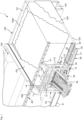
- each bulk storage box 100 is formed by two side walls 102, 102' and a rear wall 101. Between the side walls 102, 102' there is a base plate 103 on which the bulk material 1000 in 1 is stored.
- outlet openings 104 are provided in the base plate 103, through which bulk material 1000 can be discharged.
- the outlet openings 104 are present at the edge formed by the rear wall 101 and the bottom panel 103 and can be shaped in different ways: 2 shows two square outlet openings 104 in the bottom plate 103, in figure 5 a slit-shaped outlet opening 104 is introduced into the base plate 103, which extends from one side wall of the bulk goods storage box to just before the side wall 102.
- a retrieval device 105 onto which bulk material can fall for retrieval or removal through the outlet openings 104 .
- a device for moving bulk material 1000 is arranged, with the aid of which the bulk material 1000 can be arranged on the base plate 103 or pushed into the outlet openings.
- a continuous slot could be provided in the base plate.
- the slider can also be designed over the entire width. The slot could, for example, be designed with thin webs in order to make it unnecessary to move the bulk material laterally over the openings.
- the device for moving bulk material 1000 also has a pusher system which has a width which corresponds to part of the width of the rear wall 101 .
- the slider system includes a frame 11 to which the components of the slider system are attached and which can be moved along the open side of the bulk storage box 100 .
- the frame 11 has two vertical traverse elements 111, 112 as lateral support elements.
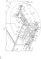
- the traverse elements 111, 112 are connected to one another at an upper end remote from the ground by a horizontal stabilizing element 14. Also this one Stabilizing element 14 is how in particular 3 and 4 show a truss element.
- rollers 15 are provided, which form a traversing device for the frame 11 .
- a telescopically extendable slide 12 is arranged on the frame, which in Figures 1 to 6 has four telescopic frame elements 20 to 23 that can be moved into one another.
- the frame 11 supports a device 18 for holding and actuating the telescoping slide 12 on the horizontal stabilizing element 14 of the frame.
- the further frame elements 21 to 23 are mounted in the first frame element 20 and the slider 12 is fastened to the last frame element 23 .
- the slider 12 can be moved to a length up to the at least one outlet opening 104, as in 3 and 4 is shown.
- the pusher 12 has foldable side elements 121 on each of its outer sides, which can be tilted at a preferably right angle or any angle between 0° and 90° by a lifting cylinder 122 on each side forward, towards the rear wall 101, can be folded.
- the telescoping sliding elements, here plate elements 20 to 23, of the slide 12 are equipped with a holding and actuating device 18 in 3 and 4 connected via cable pull elements.
- the device 18 for holding and actuating is arranged on an upper edge of the stabilizing element 14 .
- the fastening device 30 is assigned to this device.
- the fastening device 30 is positioned between the vertical traverse elements 111, 112 of the frame 11 and has two legs, each of which has a holding foot 31 to which a pivot arm 32 is attached, which is pivotally connected to the two longitudinal edges of the first frame element 20 of the slider 12 is.
- a retracted state as in 2 or figure 5 shown, which corresponds to a state of non-use of the slider system, the telescoping frame elements 21 to 23 rest against the first frame element 20 . Due to the swivel arm 32, the retracted frame elements 20 to 23 are below the horizontal Stabilizing element 14 of the frame 11 pivoted out of the bulk storage box 100 is arranged. In an extended state, the swivel arm 32 swivels the frame elements 20 to 23 out of the frame 11 and into the bulk goods storage box 100 .
- the attachment device 30, in cooperation with the device 18 for holding and actuating, also provides a lifting device for the slider 12, so that the slider 12 can be moved not only along the bottom plate 103, but also in a plane parallel to the bottom plate 103 or at an angle thereto can be moved.
- the device 18 is equipped with a cable pull system for holding and actuating, a cable 181 being connected to a motorized cable pull pulley 182 via a pulley system.
- the cable 181 is further up to a bracket 183 which is located on a third frame member 22 of the slider 12, biased.
- the cable pulley 182 is arranged laterally on one of the two swivel arms 32 and, together with the device 18 for holding and actuating, which comprises a corresponding motorized cable pulley, makes it possible to pivot the telescoping sliding elements, here the plate elements 20 to 23.
- This embodiment of the invention is based on the fact that the cable system is purely a lifting device (not shown in the figures), which defines the height of the material removal, ie the height of a bulk material accumulation. It is possible to release the slide from the material contact (bulk material contact) in the return stroke.
- the lifting movement can be carried out using a cable drum, chain hoist, hydraulic or electric cylinder.
- the telescoping movement can, for example, take place via toothed racks and motors on both sides, with an individual drive of each telescopic stage being conceivable or also a coupled telescoping of all stages at the same time.
- the frame 11 can be moved transversely (ie parallel to the rear wall 101) in front of the open side of the bulk material storage box 100, for which purpose the device for moving bulk material 1000 has a sliding device 40.
- the pushing device 40 comprises two rails 41, 42, which also extend in front of further, adjacent bulk material storage boxes 100. Between the rails 41, 42 there is a profile element 43 which is mounted so as to be displaceable along the rails 41, 42.
- the profile element 43 has recesses 44 with which the holding feet 31 of the fastening device 30 are engaged.
- the traverse elements 111, 112 of the frame 11 are mounted in or on the rails 41, 42 via their rollers 15 or elements alternative to the rollers.
- the pusher 40 may further include a third rail 45 .
- the traverse elements 111 and 112 run on the rails 41,42 as explained. These rails 41, 42 do not offer lateral guidance.
- the lower end 112', 111' of the traverse elements 111, 112 pointing in the direction of the bulk goods storage box is guided horizontally by the rail 45, which is firmly connected to the ends 112', 111' of the traverse elements 111, 112.
- This rail 45 runs on the base plate or on the base plate 103 and is held in pockets in the side walls 102 .
- the rail is consequently threaded into the pocket 106 in order to be held on both sides.
- the arrangement with the rail 45 is suitable for embodiments of the invention with or without detection devices such as the cameras 51 .
- the sliding device 40 has a second rail device 401, which is used to be able to move the frame 11 in a counter-supported manner.
- this second rail device 401 is provided at the top end on the two side walls 102, 102' of the bulk goods storage box 100, which rail device comprises a transverse beam 402.
- An upper section 17 of the frame 11 which is remote from the ground is slidably mounted along the length of this transverse beam 402 .
- the upper section 17 of the frame 11 has rollers 16 which additionally support the frame 11 against the transverse bar 402 and thus stabilize a movement of the frame 11 .
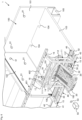
- the system 1 for storing and retrieving bulk goods also includes a detection device with which the filling quantity of the stored bulk goods 1000 is detected, as in FIG 6 is shown.
- the detection device includes some cameras 51 as optical sensors, which continuously record images of the interior of the bulk storage box 100 .
- the cameras 51 are arranged on the side walls 102, 102' and the rear wall 101 at different heights.
- a data processing unit 50 is assigned to the cameras 51 and is also electronically connected to a control device 52 in order to enable automated storage and retrieval of the bulk material 1000 .
- the data processing unit 50 can be a mobile device such as a laptop or smartphone or a fixed end device with which automated monitoring of the interior of the bulk storage box 100 is made possible. All components of the detection device are electronically connected to each other for data exchange, data processing and control of the device for moving the bulk material via suitable data connections, whether wired or wireless via a mobile network, in 6 schematized by a wireless connection 53 .
- the data processing unit 50 which can be arranged in a switch cabinet, for example, can be positioned in the vicinity of the control device 52 and thus connected to a fixed LAN connection.
- sensors for distance measurement (ultrasound) in an upper area of the side walls 102, 102' can advantageously supplement the cameras 51.
Landscapes
- Engineering & Computer Science (AREA)
- Mechanical Engineering (AREA)
- Filling Or Emptying Of Bunkers, Hoppers, And Tanks (AREA)
Priority Applications (2)
| Application Number | Priority Date | Filing Date | Title |
|---|---|---|---|
| EP23151246.8A EP4212461A1 (fr) | 2021-12-20 | 2021-12-20 | Installation pour stocker et déstocker des produits en vrac et procédé correspondant |
| EP21216035.2A EP4197944B8 (fr) | 2021-12-20 | 2021-12-20 | Installation de chargement et de déchargement de matière en vrac et procédé associé |
Applications Claiming Priority (1)
| Application Number | Priority Date | Filing Date | Title |
|---|---|---|---|
| EP21216035.2A EP4197944B8 (fr) | 2021-12-20 | 2021-12-20 | Installation de chargement et de déchargement de matière en vrac et procédé associé |
Related Child Applications (2)
| Application Number | Title | Priority Date | Filing Date |
|---|---|---|---|
| EP23151246.8A Division-Into EP4212461A1 (fr) | 2021-12-20 | 2021-12-20 | Installation pour stocker et déstocker des produits en vrac et procédé correspondant |
| EP23151246.8A Division EP4212461A1 (fr) | 2021-12-20 | 2021-12-20 | Installation pour stocker et déstocker des produits en vrac et procédé correspondant |
Publications (3)
| Publication Number | Publication Date |
|---|---|
| EP4197944A1 true EP4197944A1 (fr) | 2023-06-21 |
| EP4197944B1 EP4197944B1 (fr) | 2024-05-08 |
| EP4197944B8 EP4197944B8 (fr) | 2024-10-23 |
Family
ID=78957444
Family Applications (2)
| Application Number | Title | Priority Date | Filing Date |
|---|---|---|---|
| EP21216035.2A Active EP4197944B8 (fr) | 2021-12-20 | 2021-12-20 | Installation de chargement et de déchargement de matière en vrac et procédé associé |
| EP23151246.8A Pending EP4212461A1 (fr) | 2021-12-20 | 2021-12-20 | Installation pour stocker et déstocker des produits en vrac et procédé correspondant |
Family Applications After (1)
| Application Number | Title | Priority Date | Filing Date |
|---|---|---|---|
| EP23151246.8A Pending EP4212461A1 (fr) | 2021-12-20 | 2021-12-20 | Installation pour stocker et déstocker des produits en vrac et procédé correspondant |
Country Status (1)
| Country | Link |
|---|---|
| EP (2) | EP4197944B8 (fr) |
Citations (6)
| Publication number | Priority date | Publication date | Assignee | Title |
|---|---|---|---|---|
| GB844441A (en) * | 1956-03-29 | 1960-08-10 | Grant Lyon And Company Ltd | Improvements in or relating to apparatus for the unloading of vehicles |
| EP0283697A1 (fr) | 1987-03-13 | 1988-09-28 | Krupp Polysius Ag | Dispositif pour stocker et prélever des matières en vrac dans des terrils |
| US20130216340A1 (en) * | 2012-02-20 | 2013-08-22 | Jason Luster | Bin sweep |
| US20190256305A1 (en) * | 2011-04-22 | 2019-08-22 | Sudenga Industries, In.c | Bin sweep with weight-sensitive link |
| CN110683375A (zh) * | 2019-11-19 | 2020-01-14 | 湖北中烟工业有限责任公司 | 一种气净式w型底槽烟草原料仓 |
| CN112551189A (zh) * | 2020-12-18 | 2021-03-26 | 晶测自动化(深圳)有限公司 | 一种集装箱或者箱型卡车散件快速卸货装置与方法 |
Family Cites Families (2)
| Publication number | Priority date | Publication date | Assignee | Title |
|---|---|---|---|---|
| US3891099A (en) * | 1974-01-31 | 1975-06-24 | Glaus Pyle Schomer Burns And D | Material storage and transfer device |
| JPS5781202U (fr) * | 1980-11-05 | 1982-05-19 |
-
2021
- 2021-12-20 EP EP21216035.2A patent/EP4197944B8/fr active Active
- 2021-12-20 EP EP23151246.8A patent/EP4212461A1/fr active Pending
Patent Citations (6)
| Publication number | Priority date | Publication date | Assignee | Title |
|---|---|---|---|---|
| GB844441A (en) * | 1956-03-29 | 1960-08-10 | Grant Lyon And Company Ltd | Improvements in or relating to apparatus for the unloading of vehicles |
| EP0283697A1 (fr) | 1987-03-13 | 1988-09-28 | Krupp Polysius Ag | Dispositif pour stocker et prélever des matières en vrac dans des terrils |
| US20190256305A1 (en) * | 2011-04-22 | 2019-08-22 | Sudenga Industries, In.c | Bin sweep with weight-sensitive link |
| US20130216340A1 (en) * | 2012-02-20 | 2013-08-22 | Jason Luster | Bin sweep |
| CN110683375A (zh) * | 2019-11-19 | 2020-01-14 | 湖北中烟工业有限责任公司 | 一种气净式w型底槽烟草原料仓 |
| CN112551189A (zh) * | 2020-12-18 | 2021-03-26 | 晶测自动化(深圳)有限公司 | 一种集装箱或者箱型卡车散件快速卸货装置与方法 |
Also Published As
| Publication number | Publication date |
|---|---|
| EP4197944B1 (fr) | 2024-05-08 |
| EP4212461A1 (fr) | 2023-07-19 |
| EP4197944B8 (fr) | 2024-10-23 |
Similar Documents
| Publication | Publication Date | Title |
|---|---|---|
| DE10255843B4 (de) | Teleskopfördereinrichtung | |
| EP2444341B1 (fr) | Dispositif de traitement de produits en vrac d'une unité de transport, notamment d'un conteneur interchangeable et dispositif de déchargement | |
| DE68913047T2 (de) | Vorrichtung zum verladen von gefüllten säcken oder dergleichen in in längsrichtung offene behälter oder entsprechende laderäume. | |
| EP0264925B1 (fr) | Procédé pour charger et décharger un récipient creux, tel qu'un silo, conteneur ou semblable sur/d'un véhicule à l'aide d'un dispositif interchangeable, dispositif interchangeable pour la réalisation de ce procédé ainsi que récipient utilisé pour la réalisation de ce procédé | |
| EP2390185B1 (fr) | Transporteur de conteneur | |
| WO2008031718A1 (fr) | Plate-forme pour porter et transporter des charges à fond roulant, et dispositif de transport équipé d'une telle plate-forme | |
| DE102014002480A1 (de) | Verfahren und Einrichtung zum Nivellieren und Verbinden von mindestens zwei in einer Reihe auf einem Untergrund abgestellten begehbaren Container-Modulen zu einem modularen Gebäude | |
| DE102022132923B4 (de) | Logistiksystem | |
| DE102011002710A1 (de) | Entladevorrichtung | |
| DE102014102165A1 (de) | Vorrichtung und Verfahren zum Umladen von Ladungseinheiten | |
| EP4197944B1 (fr) | Installation de chargement et de déchargement de matière en vrac et procédé associé | |
| DE102012009434A1 (de) | Hubvorrichtung sowie Güterumschlagvorrichtung und Güterumschlagverfahren mit zumindest einer derartigen Hubvorrichtung | |
| DE102015115323A1 (de) | Regalbediengerät | |
| EP2743214B1 (fr) | Dispositif de chargement ou de déchargement et appareil de déplacement et de levage pour le chargement ou le déchargement d'étagères | |
| EP0298147A1 (fr) | Dispositif de chargement et de déchargement, en particulier de bateaux avec articles, en particulier de palettes chargées | |
| DE102023127255B4 (de) | Verfahren und Vorrichtung zum Kommissionieren von Stückgut in einen Rollbehälter | |
| DE2143078C3 (de) | Durchlauftrockner zum Trocknen druckfeuchter Druckereierzeugnisse | |
| EP0118586A2 (fr) | Véhicule porte-conteneur | |
| DE4417904A1 (de) | Verfahren und Vorrichtungen zum Befüllen sowie zum Aufeinanderstapeln von Behältern | |
| CH700505B1 (de) | Stanzanlage mit Hubvorrichtung. | |
| DE450850C (de) | Verfahren und Vorrichtung zur Aufstapelung und Weiterbefoerderung von Ziegeln, welche auf der Strangpresse hergestellt werden | |
| DE1657462B1 (de) | Vorrichtung zum automatischen Laden von Erntegut auf einen Transportwagen | |
| DE1657462C (de) | Vorrichtung zum automatischen Laden von Erntegut auf einen Transportwagen | |
| DE3814397A1 (de) | Einrichtung zur aufnahme des aus mindestens einer filterpresse ausgetragenen filterkuchens und zur befoerderung des aufgenommenen filterkuchens zu einer uebergabestation | |
| DE10116005B4 (de) | Werkzeugübergabevorrichtung |
Legal Events
| Date | Code | Title | Description |
|---|---|---|---|
| PUAI | Public reference made under article 153(3) epc to a published international application that has entered the european phase |
Free format text: ORIGINAL CODE: 0009012 |
|
| STAA | Information on the status of an ep patent application or granted ep patent |
Free format text: STATUS: REQUEST FOR EXAMINATION WAS MADE |
|
| 17P | Request for examination filed |
Effective date: 20230328 |
|
| AK | Designated contracting states |
Kind code of ref document: A1 Designated state(s): AL AT BE BG CH CY CZ DE DK EE ES FI FR GB GR HR HU IE IS IT LI LT LU LV MC MK MT NL NO PL PT RO RS SE SI SK SM TR |
|
| GRAJ | Information related to disapproval of communication of intention to grant by the applicant or resumption of examination proceedings by the epo deleted |
Free format text: ORIGINAL CODE: EPIDOSDIGR1 |
|
| GRAP | Despatch of communication of intention to grant a patent |
Free format text: ORIGINAL CODE: EPIDOSNIGR1 |
|
| GRAP | Despatch of communication of intention to grant a patent |
Free format text: ORIGINAL CODE: EPIDOSNIGR1 |
|
| STAA | Information on the status of an ep patent application or granted ep patent |
Free format text: STATUS: GRANT OF PATENT IS INTENDED |
|
| INTG | Intention to grant announced |
Effective date: 20240216 |
|
| GRAS | Grant fee paid |
Free format text: ORIGINAL CODE: EPIDOSNIGR3 |
|
| GRAA | (expected) grant |
Free format text: ORIGINAL CODE: 0009210 |
|
| STAA | Information on the status of an ep patent application or granted ep patent |
Free format text: STATUS: THE PATENT HAS BEEN GRANTED |
|
| AK | Designated contracting states |
Kind code of ref document: B1 Designated state(s): AL AT BE BG CH CY CZ DE DK EE ES FI FR GB GR HR HU IE IS IT LI LT LU LV MC MK MT NL NO PL PT RO RS SE SI SK SM TR |
|
| REG | Reference to a national code |
Ref country code: GB Ref legal event code: FG4D Free format text: NOT ENGLISH |
|
| REG | Reference to a national code |
Ref country code: CH Ref legal event code: EP |
|
| REG | Reference to a national code |
Ref country code: DE Ref legal event code: R096 Ref document number: 502021003653 Country of ref document: DE |
|
| REG | Reference to a national code |
Ref country code: IE Ref legal event code: FG4D Free format text: LANGUAGE OF EP DOCUMENT: GERMAN |
|
| REG | Reference to a national code |
Ref country code: LT Ref legal event code: MG9D |
|
| GRAT | Correction requested after decision to grant or after decision to maintain patent in amended form |
Free format text: ORIGINAL CODE: EPIDOSNCDEC |
|
| REG | Reference to a national code |
Ref country code: NL Ref legal event code: MP Effective date: 20240508 |
|
| REG | Reference to a national code |
Ref country code: CH Ref legal event code: PK Free format text: BERICHTIGUNG B8 Ref country code: CH Ref legal event code: PK Free format text: BERICHTIGUNGEN |
|
| PG25 | Lapsed in a contracting state [announced via postgrant information from national office to epo] |
Ref country code: IS Free format text: LAPSE BECAUSE OF FAILURE TO SUBMIT A TRANSLATION OF THE DESCRIPTION OR TO PAY THE FEE WITHIN THE PRESCRIBED TIME-LIMIT Effective date: 20240908 |
|
| PG25 | Lapsed in a contracting state [announced via postgrant information from national office to epo] |
Ref country code: BG Free format text: LAPSE BECAUSE OF FAILURE TO SUBMIT A TRANSLATION OF THE DESCRIPTION OR TO PAY THE FEE WITHIN THE PRESCRIBED TIME-LIMIT Effective date: 20240508 |
|
| PG25 | Lapsed in a contracting state [announced via postgrant information from national office to epo] |
Ref country code: HR Free format text: LAPSE BECAUSE OF FAILURE TO SUBMIT A TRANSLATION OF THE DESCRIPTION OR TO PAY THE FEE WITHIN THE PRESCRIBED TIME-LIMIT Effective date: 20240508 Ref country code: FI Free format text: LAPSE BECAUSE OF FAILURE TO SUBMIT A TRANSLATION OF THE DESCRIPTION OR TO PAY THE FEE WITHIN THE PRESCRIBED TIME-LIMIT Effective date: 20240508 |
|
| PG25 | Lapsed in a contracting state [announced via postgrant information from national office to epo] |
Ref country code: GR Free format text: LAPSE BECAUSE OF FAILURE TO SUBMIT A TRANSLATION OF THE DESCRIPTION OR TO PAY THE FEE WITHIN THE PRESCRIBED TIME-LIMIT Effective date: 20240809 |
|
| PG25 | Lapsed in a contracting state [announced via postgrant information from national office to epo] |
Ref country code: PT Free format text: LAPSE BECAUSE OF FAILURE TO SUBMIT A TRANSLATION OF THE DESCRIPTION OR TO PAY THE FEE WITHIN THE PRESCRIBED TIME-LIMIT Effective date: 20240909 |
|
| RIN2 | Information on inventor provided after grant (corrected) |
Inventor name: VONHOFF, AXEL Inventor name: ZUERCHER, RALF |
|
| PG25 | Lapsed in a contracting state [announced via postgrant information from national office to epo] |
Ref country code: NL Free format text: LAPSE BECAUSE OF FAILURE TO SUBMIT A TRANSLATION OF THE DESCRIPTION OR TO PAY THE FEE WITHIN THE PRESCRIBED TIME-LIMIT Effective date: 20240508 |
|
| PG25 | Lapsed in a contracting state [announced via postgrant information from national office to epo] |
Ref country code: ES Free format text: LAPSE BECAUSE OF FAILURE TO SUBMIT A TRANSLATION OF THE DESCRIPTION OR TO PAY THE FEE WITHIN THE PRESCRIBED TIME-LIMIT Effective date: 20240508 |
|
| PG25 | Lapsed in a contracting state [announced via postgrant information from national office to epo] |
Ref country code: PL Free format text: LAPSE BECAUSE OF FAILURE TO SUBMIT A TRANSLATION OF THE DESCRIPTION OR TO PAY THE FEE WITHIN THE PRESCRIBED TIME-LIMIT Effective date: 20240508 |
|
| PG25 | Lapsed in a contracting state [announced via postgrant information from national office to epo] |
Ref country code: LV Free format text: LAPSE BECAUSE OF FAILURE TO SUBMIT A TRANSLATION OF THE DESCRIPTION OR TO PAY THE FEE WITHIN THE PRESCRIBED TIME-LIMIT Effective date: 20240508 |
|
| PG25 | Lapsed in a contracting state [announced via postgrant information from national office to epo] |
Ref country code: PT Free format text: LAPSE BECAUSE OF FAILURE TO SUBMIT A TRANSLATION OF THE DESCRIPTION OR TO PAY THE FEE WITHIN THE PRESCRIBED TIME-LIMIT Effective date: 20240909 Ref country code: PL Free format text: LAPSE BECAUSE OF FAILURE TO SUBMIT A TRANSLATION OF THE DESCRIPTION OR TO PAY THE FEE WITHIN THE PRESCRIBED TIME-LIMIT Effective date: 20240508 Ref country code: NO Free format text: LAPSE BECAUSE OF FAILURE TO SUBMIT A TRANSLATION OF THE DESCRIPTION OR TO PAY THE FEE WITHIN THE PRESCRIBED TIME-LIMIT Effective date: 20240808 Ref country code: NL Free format text: LAPSE BECAUSE OF FAILURE TO SUBMIT A TRANSLATION OF THE DESCRIPTION OR TO PAY THE FEE WITHIN THE PRESCRIBED TIME-LIMIT Effective date: 20240508 Ref country code: LV Free format text: LAPSE BECAUSE OF FAILURE TO SUBMIT A TRANSLATION OF THE DESCRIPTION OR TO PAY THE FEE WITHIN THE PRESCRIBED TIME-LIMIT Effective date: 20240508 Ref country code: IS Free format text: LAPSE BECAUSE OF FAILURE TO SUBMIT A TRANSLATION OF THE DESCRIPTION OR TO PAY THE FEE WITHIN THE PRESCRIBED TIME-LIMIT Effective date: 20240908 Ref country code: HR Free format text: LAPSE BECAUSE OF FAILURE TO SUBMIT A TRANSLATION OF THE DESCRIPTION OR TO PAY THE FEE WITHIN THE PRESCRIBED TIME-LIMIT Effective date: 20240508 Ref country code: GR Free format text: LAPSE BECAUSE OF FAILURE TO SUBMIT A TRANSLATION OF THE DESCRIPTION OR TO PAY THE FEE WITHIN THE PRESCRIBED TIME-LIMIT Effective date: 20240809 Ref country code: FI Free format text: LAPSE BECAUSE OF FAILURE TO SUBMIT A TRANSLATION OF THE DESCRIPTION OR TO PAY THE FEE WITHIN THE PRESCRIBED TIME-LIMIT Effective date: 20240508 Ref country code: ES Free format text: LAPSE BECAUSE OF FAILURE TO SUBMIT A TRANSLATION OF THE DESCRIPTION OR TO PAY THE FEE WITHIN THE PRESCRIBED TIME-LIMIT Effective date: 20240508 Ref country code: BG Free format text: LAPSE BECAUSE OF FAILURE TO SUBMIT A TRANSLATION OF THE DESCRIPTION OR TO PAY THE FEE WITHIN THE PRESCRIBED TIME-LIMIT Effective date: 20240508 Ref country code: RS Free format text: LAPSE BECAUSE OF FAILURE TO SUBMIT A TRANSLATION OF THE DESCRIPTION OR TO PAY THE FEE WITHIN THE PRESCRIBED TIME-LIMIT Effective date: 20240808 |
|
| REG | Reference to a national code |
Ref country code: DE Ref legal event code: R083 Ref document number: 502021003653 Country of ref document: DE |
|
| PG25 | Lapsed in a contracting state [announced via postgrant information from national office to epo] |
Ref country code: DK Free format text: LAPSE BECAUSE OF FAILURE TO SUBMIT A TRANSLATION OF THE DESCRIPTION OR TO PAY THE FEE WITHIN THE PRESCRIBED TIME-LIMIT Effective date: 20240508 |
|
| PGFP | Annual fee paid to national office [announced via postgrant information from national office to epo] |
Ref country code: FR Payment date: 20241216 Year of fee payment: 4 |
|
| PG25 | Lapsed in a contracting state [announced via postgrant information from national office to epo] |
Ref country code: EE Free format text: LAPSE BECAUSE OF FAILURE TO SUBMIT A TRANSLATION OF THE DESCRIPTION OR TO PAY THE FEE WITHIN THE PRESCRIBED TIME-LIMIT Effective date: 20240508 |
|
| PG25 | Lapsed in a contracting state [announced via postgrant information from national office to epo] |
Ref country code: CZ Free format text: LAPSE BECAUSE OF FAILURE TO SUBMIT A TRANSLATION OF THE DESCRIPTION OR TO PAY THE FEE WITHIN THE PRESCRIBED TIME-LIMIT Effective date: 20240508 |
|
| PG25 | Lapsed in a contracting state [announced via postgrant information from national office to epo] |
Ref country code: SK Free format text: LAPSE BECAUSE OF FAILURE TO SUBMIT A TRANSLATION OF THE DESCRIPTION OR TO PAY THE FEE WITHIN THE PRESCRIBED TIME-LIMIT Effective date: 20240508 Ref country code: RO Free format text: LAPSE BECAUSE OF FAILURE TO SUBMIT A TRANSLATION OF THE DESCRIPTION OR TO PAY THE FEE WITHIN THE PRESCRIBED TIME-LIMIT Effective date: 20240508 |
|
| PG25 | Lapsed in a contracting state [announced via postgrant information from national office to epo] |
Ref country code: SM Free format text: LAPSE BECAUSE OF FAILURE TO SUBMIT A TRANSLATION OF THE DESCRIPTION OR TO PAY THE FEE WITHIN THE PRESCRIBED TIME-LIMIT Effective date: 20240508 |
|
| PG25 | Lapsed in a contracting state [announced via postgrant information from national office to epo] |
Ref country code: SM Free format text: LAPSE BECAUSE OF FAILURE TO SUBMIT A TRANSLATION OF THE DESCRIPTION OR TO PAY THE FEE WITHIN THE PRESCRIBED TIME-LIMIT Effective date: 20240508 Ref country code: SK Free format text: LAPSE BECAUSE OF FAILURE TO SUBMIT A TRANSLATION OF THE DESCRIPTION OR TO PAY THE FEE WITHIN THE PRESCRIBED TIME-LIMIT Effective date: 20240508 Ref country code: RO Free format text: LAPSE BECAUSE OF FAILURE TO SUBMIT A TRANSLATION OF THE DESCRIPTION OR TO PAY THE FEE WITHIN THE PRESCRIBED TIME-LIMIT Effective date: 20240508 Ref country code: EE Free format text: LAPSE BECAUSE OF FAILURE TO SUBMIT A TRANSLATION OF THE DESCRIPTION OR TO PAY THE FEE WITHIN THE PRESCRIBED TIME-LIMIT Effective date: 20240508 Ref country code: DK Free format text: LAPSE BECAUSE OF FAILURE TO SUBMIT A TRANSLATION OF THE DESCRIPTION OR TO PAY THE FEE WITHIN THE PRESCRIBED TIME-LIMIT Effective date: 20240508 Ref country code: CZ Free format text: LAPSE BECAUSE OF FAILURE TO SUBMIT A TRANSLATION OF THE DESCRIPTION OR TO PAY THE FEE WITHIN THE PRESCRIBED TIME-LIMIT Effective date: 20240508 |
|
| PG25 | Lapsed in a contracting state [announced via postgrant information from national office to epo] |
Ref country code: IT Free format text: LAPSE BECAUSE OF FAILURE TO SUBMIT A TRANSLATION OF THE DESCRIPTION OR TO PAY THE FEE WITHIN THE PRESCRIBED TIME-LIMIT Effective date: 20240508 |
|
| REG | Reference to a national code |
Ref country code: DE Ref legal event code: R097 Ref document number: 502021003653 Country of ref document: DE |
|
| PLBE | No opposition filed within time limit |
Free format text: ORIGINAL CODE: 0009261 |
|
| STAA | Information on the status of an ep patent application or granted ep patent |
Free format text: STATUS: NO OPPOSITION FILED WITHIN TIME LIMIT |
|
| PGFP | Annual fee paid to national office [announced via postgrant information from national office to epo] |
Ref country code: DE Payment date: 20241219 Year of fee payment: 4 |
|
| 26N | No opposition filed |
Effective date: 20250211 |
|
| PG25 | Lapsed in a contracting state [announced via postgrant information from national office to epo] |
Ref country code: SI Free format text: LAPSE BECAUSE OF FAILURE TO SUBMIT A TRANSLATION OF THE DESCRIPTION OR TO PAY THE FEE WITHIN THE PRESCRIBED TIME-LIMIT Effective date: 20240508 |
|
| PGFP | Annual fee paid to national office [announced via postgrant information from national office to epo] |
Ref country code: CH Payment date: 20250101 Year of fee payment: 4 |
|
| PG25 | Lapsed in a contracting state [announced via postgrant information from national office to epo] |
Ref country code: MC Free format text: LAPSE BECAUSE OF FAILURE TO SUBMIT A TRANSLATION OF THE DESCRIPTION OR TO PAY THE FEE WITHIN THE PRESCRIBED TIME-LIMIT Effective date: 20240508 |
|
| PG25 | Lapsed in a contracting state [announced via postgrant information from national office to epo] |
Ref country code: LU Free format text: LAPSE BECAUSE OF NON-PAYMENT OF DUE FEES Effective date: 20241220 |
|
| PG25 | Lapsed in a contracting state [announced via postgrant information from national office to epo] |
Ref country code: SE Free format text: LAPSE BECAUSE OF FAILURE TO SUBMIT A TRANSLATION OF THE DESCRIPTION OR TO PAY THE FEE WITHIN THE PRESCRIBED TIME-LIMIT Effective date: 20240508 |
|
| REG | Reference to a national code |
Ref country code: BE Ref legal event code: MM Effective date: 20241231 |
|
| PG25 | Lapsed in a contracting state [announced via postgrant information from national office to epo] |
Ref country code: BE Free format text: LAPSE BECAUSE OF NON-PAYMENT OF DUE FEES Effective date: 20241231 |
|
| PG25 | Lapsed in a contracting state [announced via postgrant information from national office to epo] |
Ref country code: IE Free format text: LAPSE BECAUSE OF NON-PAYMENT OF DUE FEES Effective date: 20241220 |
|
| PGFP | Annual fee paid to national office [announced via postgrant information from national office to epo] |
Ref country code: AT Payment date: 20260113 Year of fee payment: 5 |