EP4198202B1 - Appareil d'insertion de barre de goujon et procédé de fonctionnement dudit appareil d'insertion de barre de goujon - Google Patents
Appareil d'insertion de barre de goujon et procédé de fonctionnement dudit appareil d'insertion de barre de goujon Download PDFInfo
- Publication number
- EP4198202B1 EP4198202B1 EP22211870.5A EP22211870A EP4198202B1 EP 4198202 B1 EP4198202 B1 EP 4198202B1 EP 22211870 A EP22211870 A EP 22211870A EP 4198202 B1 EP4198202 B1 EP 4198202B1
- Authority
- EP
- European Patent Office
- Prior art keywords
- actuators
- deflection compensation
- actuator
- suspension
- extension
- Prior art date
- Legal status (The legal status is an assumption and is not a legal conclusion. Google has not performed a legal analysis and makes no representation as to the accuracy of the status listed.)
- Active
Links
Images



Classifications
-
- E—FIXED CONSTRUCTIONS
- E04—BUILDING
- E04G—SCAFFOLDING; FORMS; SHUTTERING; BUILDING IMPLEMENTS OR AIDS, OR THEIR USE; HANDLING BUILDING MATERIALS ON THE SITE; REPAIRING, BREAKING-UP OR OTHER WORK ON EXISTING BUILDINGS
- E04G21/00—Preparing, conveying, or working-up building materials or building elements in situ; Other devices or measures for constructional work
- E04G21/14—Conveying or assembling building elements
- E04G21/16—Tools or apparatus
- E04G21/18—Adjusting tools; Templates
- E04G21/1841—Means for positioning building parts or elements
-
- E—FIXED CONSTRUCTIONS
- E01—CONSTRUCTION OF ROADS, RAILWAYS, OR BRIDGES
- E01C—CONSTRUCTION OF, OR SURFACES FOR, ROADS, SPORTS GROUNDS, OR THE LIKE; MACHINES OR AUXILIARY TOOLS FOR CONSTRUCTION OR REPAIR
- E01C23/00—Auxiliary devices or arrangements for constructing, repairing, reconditioning, or taking-up road or like surfaces
- E01C23/04—Devices for laying inserting or positioning reinforcing elements or dowel bars with or without joint bodies; Removable supports for reinforcing or load transfer elements; Devices, e.g. removable forms, for making essentially horizontal ducts in paving, e.g. for prestressed reinforcements
-
- E—FIXED CONSTRUCTIONS
- E01—CONSTRUCTION OF ROADS, RAILWAYS, OR BRIDGES
- E01C—CONSTRUCTION OF, OR SURFACES FOR, ROADS, SPORTS GROUNDS, OR THE LIKE; MACHINES OR AUXILIARY TOOLS FOR CONSTRUCTION OR REPAIR
- E01C19/00—Machines, tools or auxiliary devices for preparing or distributing paving materials, for working the placed materials, or for forming, consolidating, or finishing the paving
- E01C19/48—Machines, tools or auxiliary devices for preparing or distributing paving materials, for working the placed materials, or for forming, consolidating, or finishing the paving for laying-down the materials and consolidating them, or finishing the surface, e.g. slip forms therefor, forming kerbs or gutters in a continuous operation in situ
- E01C19/4833—Machines, tools or auxiliary devices for preparing or distributing paving materials, for working the placed materials, or for forming, consolidating, or finishing the paving for laying-down the materials and consolidating them, or finishing the surface, e.g. slip forms therefor, forming kerbs or gutters in a continuous operation in situ with tamping or vibrating means for consolidating or finishing, e.g. immersed vibrators, with or without non-vibratory or non-percussive pressing or smoothing means
-
- E—FIXED CONSTRUCTIONS
- E01—CONSTRUCTION OF ROADS, RAILWAYS, OR BRIDGES
- E01C—CONSTRUCTION OF, OR SURFACES FOR, ROADS, SPORTS GROUNDS, OR THE LIKE; MACHINES OR AUXILIARY TOOLS FOR CONSTRUCTION OR REPAIR
- E01C19/00—Machines, tools or auxiliary devices for preparing or distributing paving materials, for working the placed materials, or for forming, consolidating, or finishing the paving
- E01C19/48—Machines, tools or auxiliary devices for preparing or distributing paving materials, for working the placed materials, or for forming, consolidating, or finishing the paving for laying-down the materials and consolidating them, or finishing the surface, e.g. slip forms therefor, forming kerbs or gutters in a continuous operation in situ
Definitions
- the present disclosure relates to a dowel bar inserter apparatus for inserting dowel bars in a freshly placed concrete slab, and to methods of operation of such an apparatus.
- a dowel bar inserter apparatus includes a bottom pan assembly, sometimes referred to as a bottom-group assembly.
- the bottom pan assembly is the structure that slides across the top of the freshly placed concrete slab, and from which the dowel bars are inserted into the concrete slab.
- Modern slip form pavers and the associated dowel bar inserters must span large widths, up to as much as 15,24 m (50 feet).
- the bottom pan assembly is supported from the structure of the dowel bar inserter which in turn is typically supported from the main frame of the associated slip form paver.
- This support is typically proved by a series of threaded rods which must be manually adjusted during the set-up of the dowel bar inserter for a given paving job. If height corrections of the bottom pan assembly are necessary during the paving operation, again these adjustments are typically made by further manual adjustment of the threaded support rods.
- Such height corrections of the bottom pan assembly are often necessitated by changes which may occur in the consistency of the concrete during the paving operation. Such changes in consistency may occur across the working width of the dowel bar inserter and/or in the paving direction.
- Such manual corrections of the height of the bottom pan assembly are needed they often can only be carried out by a human operator stepping onto the freshly paved concrete surface to adjust the threaded support rods, and access to those mechanical components is often difficult. But it is very undesirable for the operator to step onto the concrete surface because that may influence the position of dowel bars that have already been inserted.
- a dowel bar inserter apparatus includes first and second end carriages, a bottom pan assembly configured to engage a top surface of a freshly placed concrete slab, an insertion beam having a plurality of insertion forks attached to the insertion beam, and first and second insertion actuators supporting the insertion beam from the first and second end carriages, respectively, for raising and lowering the insertion beam and the insertion forks relative to the end carriages.
- At least one first suspension actuator supports the bottom pan assembly from the first end carriage independent of the raising and lowering of the insertion beam relative to the first end carriage.
- At least one second suspension actuator supports the bottom pan assembly from the second end carriage independent of the raising and lowering of the insertion beam relative to the second end carriage.
- Each of the suspension actuators includes associated therewith a suspension actuator extension sensor configured to detect an amount of extension of the respective suspension actuator.
- the at least one first end suspension actuator may include a forward first end suspension actuator and a rear first end suspension actuator.
- the at least one second end suspension actuator may include a forward second end suspension actuator and a rear second end suspension actuator.
- each of the suspension actuators may be a hydraulic cylinder.
- each of the suspension actuators may comprise a hydraulic smart cylinder, and the suspension actuator extension sensor associated with each suspension actuator may be an integral part of the hydraulic smart cylinder.
- the dowel bar inserter may include a plurality of deflection compensation actuators configured to support a plurality of intermediate locations of the bottom pan assembly, the deflection compensation actuators being located between the first and second suspension actuators.
- each of the deflection compensation actuators may include a hydraulic cylinder and a flexible connector connecting the hydraulic cylinder to the bottom pan assembly such that the deflection compensation actuators can support the bottom pan assembly in tension loading but not compression loading of the flexible connectors.
- each of the hydraulic cylinders of the deflection compensation actuators may comprise a hydraulic smart cylinder including an integral deflection compensation actuator extension sensor.
- each of the deflection compensation actuators may be connected to the insertion beam so that the plurality of intermediate locations of the bottom pan assembly are supported from the insertion beam.
- each of the deflection compensation actuators may be connected to a support structure fixed to the first and second end carriages so that the plurality of intermediate locations of the bottom pan assembly are supported from the support structure.
- the deflection compensation actuators may be arranged in pairs of deflection compensation actuators, each pair including a front deflection compensation actuator and a rear deflection compensation actuator.
- the dowel bar inserter may include a chain conveyor configured to carry dowel bars to the bottom pan assembly and a hydraulic chain tensioning cylinder configured to maintain a tension in the chain conveyor.
- each of the suspension actuator extension sensors may be configured to generate a suspension actuator extension signal corresponding to the amount of extension of the respective suspension actuator
- the dowel bar inserter may further include a controller configured to receive the suspension actuator extension signals and to send control signals to the respective suspension actuators, at least in part in response to the suspension actuator extension signals for the respective suspension actuators.
- the dowel bar inserter may include a plurality of deflection compensation actuators configured to support a plurality of intermediate locations of the bottom pan assembly from the insertion beam, each of the deflection compensation actuators including a hydraulic smart cylinder including an integral deflection compensation actuator extension sensor, and the controller may be further configured to receive deflection compensation actuator extension signals from the deflection compensation actuator extension sensors corresponding to an extension of the respective deflection compensation actuators, and to send control signals to the respective deflection compensation actuators, at least in part in response to the deflection compensation actuator extension signals for the respective deflection compensation actuators.
- the dowel bar inserter may include at least one dowel bar storage bin located above the first end carriage, a chain conveyor configured to carry dowel bars from the at least one dowel bar storage bin to the bottom pan assembly, and an adjustable height support supporting the at least one dowel bar storage bin at an adjustable height above the first end carriage such that adjustment of the height of the at least one dowel bar storage bin above the first end carriage provides an initial adjustment of a chain tension in the chain conveyor during setup of the dowel bar inserter apparatus.
- the dowel bar inserter may include at least one hydraulic chain tensioning cylinder or other tensioning device extending between the first end carriage and the chain conveyor and configured to provide a further adjustment of chain tension in the chain conveyor during operation of the dowel bar inserter apparatus. Similar hydraulic chain tensioning cylinders may extend between the second end carriage and the chain conveyor.
- the dowel bar inserter may include at least one chain conveyor configured to carry dowel bars to the bottom pan assembly, a chain tensioning actuator configured to maintain a tension in the chain conveyor, a chain tensioning sensor, and a controller configured to receive a chain tension signal from the chain tensioning sensor and to send a control signal to the chain tensioning actuator, at least in part in response to the chain tension signal.
- the at least one first end suspension actuator may include a forward first end suspension actuator and a rear first end suspension actuator
- the at least one second end suspension actuator may include a forward second end suspension actuator and a rear second end suspension actuator.
- the controller may be configured to adjust the amount of extension of the forward first end suspension actuator and the forward second end suspension actuator relative to the amount of extension of the rear first end suspension actuator and the rear second end suspension actuator, respectively, to adjust a front to rear slope of the bottom pan assembly.
- the dowel bar inserter may include a plurality of deflection compensation actuators configured to support a plurality of intermediate locations of the bottom pan assembly, the deflection compensation actuators being located between the first and second suspension actuators, the deflection compensation actuators being arranged in pairs of deflection compensation actuators, each pair including a front deflection compensation actuator and a rear deflection compensation actuator, and the controller may be further configured to adjust an amount of extension of the front deflection compensation actuators relative to an amount of extension of the rear deflection compensation actuators to adjust the front to rear slope of the bottom pan assembly.
- the dowel bar inserter may include a swelling sensor configured to detect a swelling of the concrete slab and the controller may be configured to receive a signal from the swelling sensor corresponding to the swelling of the concrete slab, and to adjust the front to rear slope of the bottom pan assembly at least in part in response to the signal from the swelling sensor.
- the swelling sensor may be mounted on the dowel bar inserter itself or it may be mounted on other associated structures such as the paving mold which is a part of the paving apparatus located ahead of the dowel bar inserter.
- controller may be further configured to adjust all of the suspension actuators to raise the entire bottom pan assembly at least in part in response to the signal from the swelling sensor.
- the controller may be configured to have a transport mode in which all of the suspension actuators are adjusted to raise the bottom pan assembly to a transport position.
- the above method may further include:
- Any of the above methods may further include:
- Any of the above methods may further include: sending control signals from the controller to adjust the amount of extension of the forward first end suspension actuator and the forward second end suspension actuator relative to the amount of extension of the rear first end suspension actuator and the rear second end suspension actuator, respectively, thereby adjusting a front to rear slope of the bottom pan assembly, wherein the at least one first end suspension actuator includes a forward first end suspension actuator and a rear first end suspension actuator, and the at least one second end suspension actuator includes a forward second end suspension actuator and a rear second end suspension actuator.
- Any of the above methods may further include: sending control signals from the controller to adjust an amount of extension of the front deflection compensation actuators relative to an amount of extension of the rear deflection compensation actuators to adjust the front to rear slope of the bottom pan assembly, wherein the apparatus further includes a plurality of deflection compensation actuators configured to support a plurality of intermediate locations of the bottom pan assembly, the deflection compensation actuators being located between the first and second suspension actuators, the deflection compensation actuators being arranged in pairs of deflection compensation actuators, each pair including a front deflection compensation actuator and a rear deflection compensation actuator.
- Any of the above methods may further include:
- Any of the above methods may further include: sending control signals from the controller to retract all of the suspension actuators and thereby raising the entire bottom pan assembly at least in part in response to the signal from the swelling sensor.
- Any of the above methods may further include: sending control signals from the controller to retract all of the suspension actuators to raise the bottom pan assembly to a transport position.
- a slip form paver apparatus is shown and generally designated by the number 10.
- the apparatus 10 is configured to move in a paving direction 12 across a ground surface 14 for spreading, leveling and finishing concrete into a finished concrete structure 16 having a generally upwardly exposed concrete surface 18 and terminating in lateral concrete sides such as 20.
- the slip form paver apparatus 10 includes a main frame 22 and a slip form paver mold 24 supported from the main frame 22. Left and right side form assemblies 26 are connected to the slip form paver mold 24 to close the slip form paver mold 24 on the left and right sides to form the lateral concrete sides such as 20 of the finished concrete structure 16.
- the slip form paver apparatus 10 shown in Fig. 1 is an inset type slip form paver apparatus.
- the main frame 22 is supported from the ground surface by a plurality of ground engaging units such as 30, which in the illustrated embodiment are tracked ground engaging units 30. Wheeled ground engaging units may also be used.
- Each of the ground engaging units 30 is connected to the main frame 22 by a lifting column such as 32 which is attached to a swing arm such as 34.
- An operator's station 36 is located on the main frame 22.
- a plow or spreader device 38 is supported from the main frame 22 ahead of the slip form paver mold 24. Behind the slip form paver mold 24 a dowel bar inserter apparatus 40 may be provided. Behind the dowel bar inserter apparatus 40 an oscillating beam 41 and a super smoother apparatus 42 may be provided.
- the present disclosure is focused on the construction of the dowel bar inserter 40.
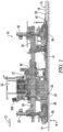
- Fig. 2 shows a partially sectioned rear perspective view
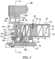
- Fig. 3 shows an enlarged rear elevation view of the left end portion of the dowel bar inserter 40.
- the dowel bar inserter 40 is an apparatus for inserting short lengths of reinforcing bar, referred to as dowel bars 79 (see Figs. 9 and 10 ), into the freshly poured concrete slab 16.
- the dowel bar inserter 40 includes first and second end carriages 44 and 46. As can be seen in Fig. 2 the first or left end carriage 44 is shown in place on a lengthwise rail 48 which may be a part of the main frame 22 of the slip form paver 10, or which may be a separate rail attached to the rear of the main frame 22. The corresponding rail on the right side for the second or right end carriage 46 is not shown so that the construction of the second end carriage 46 may be seen.
- the end carriages each include a C-shape lateral opening such as 50 which is received on the respective rail such as 48 so that the dowel bar inserter 40 may move forward and backward relative to the main frame 22 during the dowel bar insertion operation.
- the dowel bar inserter 40 includes bottom pan assembly 52 which slides across the top surface 18 of the concrete slab 16 during the paving operation.
- the bottom pan assembly 52 includes a forward pan beam 54, a rearward pan beam 56, and a series of pan sections 58 attached to the pan beams and having spaces 60 between adjacent pan sections.
- the pan section 58 may extend in one or more segments across the width of the dowel bar inserter 40 and the spaces 60 may be formed in the pan section 58 itself. As further described below the dowel bars are pushed downward through the spaces 60 into the freshly poured concrete slab 16.
- the dowel bar inserter 40 slides forward and backward on the rails 48 during the dowel bar insertion operation.
- the slip form paver 10 moves forward continuously.
- the dowel bar inserter 40 reaches a location where a group of dowel bars 79 are to be inserted the dowel bar inserter 40 is held stationary relative to the ground surface 14 and the slab 16 while the slip form paver 10 continues to move forward.
- This temporary stopping of the dowel bar inserter 40 is achieved by sliding the dowel bar inserter rearward on rails 48 at the same speed at which the slip form paver 10 is advancing.
- the dowel bar inserter 40 is stationary over the slab 16 a set of dowel bars is inserted. Then the dowel bar inserter 40 is moved forward on the rails 48 back to its initial forward position and it is ready to perform the next insertion cycle.
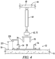
- FIG. 4 is a schematic left end view of the dowel bar inserter 40 taken along line 4-4 of Fig. 3 .
- Fig. 4 shows a portion of the left end carriage 44 with a first insertion actuator 64 having its upper end attached to a cross-beam 68 of left end carriage 44 and having its lower end connected to the insertion beam 62.
- a similar second insertion actuator 66 is connected between the right end carriage 46 and the insertion beam 62.
- the insertion beam 62 is a truss structure including an upper beam channel 70, a lower beam channel 72, a plurality of vertical supports 74 and a plurality of diagonal supports 76 extending between the upper and lower beam channels 70 and 72.
- the lower ends of the first and second insertion actuators 64 and 66 may be attached to the lower beam channel 72 as seen in Fig. 4 .
- a plurality of insertion forks 78 are attached to the insertion beam 62.
- the insertion forks 78 push the dowel bars through the spaces 60 down into the freshly poured concrete slab 16.
- Upper and lower positions of the insertion beam 62 are schematically shown in Figs. 9 and 10 .
- the insertion beam 62 is in a raised position relative to bottom pan assembly 52 and the insertion forks 78 are engaged with dowel bars 79 which are being held in the bottom pan assembly 52.
- the insertion beam has been lowered by the insertion actuators 64 and 66 to a lower position relative to the bottom pan assembly 52 wherein the dowel bars 79 have been pushed by the insertion forks 78 down into the freshly poured concrete slab 16.
- first and second insertion actuators 64 and 66 may be hydraulic "smart" cylinders such as are further described below with reference to Fig. 5 .
- FIG. 3 the details of construction of the left end carriage 44 can be seen.
- the right end carriage 46 is a mirror image.
- Left end carriage 44 includes a main carriage body 80.
- Front and rear support legs 82 are attached to and extend downward from carriage body 80.
- the rear support leg 82 is seen in Fig. 3 .
- the bottom pan assembly 52 is supported from the support legs such as 82 of the left and right end carriages 44, 46 by four suspension actuators 84, 86, 88 and 90.
- the left rear suspension actuator 84 is shown having its upper end connected to the left rear support leg 82 of the left end carriage 44 and having its lower end connected to the left end of the rear pan beam 56 of bottom pan assembly 52. Retraction and extension of the left rear suspension actuator 84 raises and lowers the left rear corner of the bottom pan assembly 52.
- the right rear suspension actuator 86 supports the right end of rear pan beam 56
- the left and right front suspension actuators 88 and 90 support the left and right ends of the front pan beam 54.
- each of the suspension actuators 84, 86, 88 and 90 is independently controllable. Thus, all the suspension actuators may be simultaneously or separately retracted or extended. In one embodiment all the suspension actuators may be simultaneously retracted or extended to raise or lower the bottom pan assembly 52. In another embodiment the front suspension actuators 88 and 90 may be raised more than the rear suspension actuators 84 and 86 to adjust a front to rear slope of the bottom pan assembly 52. In a further embodiment the left end suspension actuators 84 and 88 may be extended differently from the right end suspension actuators 86 and 90 to provide a cross slope of the bottom pan assembly 52.
- the dowel bar inserter 40 may be described as having at least one first end suspension actuator 84 and/or 88 for supporting the bottom pan assembly 52 from the first end carriage 44 independent of the raising and lowering of the insertion beam 62 relative to the first end carriage 44.
- the dowel bar inserter 40 may be described as having at least one second end suspension actuator 86 and/or 90 for supporting the bottom pan assembly 52 from the second end carriage 46 independent of the raising and lowering of the insertion beam 62 relative to the second end carriage 46.
- suspension actuators 84, 86, 88 and 90 may each have associated therewith a suspension actuator extension sensor 84S, 86S, 88S and 90S, respectively, configured to detect an amount of extension of the respective suspension actuator.
- each of the suspension actuators may be a hydraulic cylinder.
- the hydraulic cylinders may each be a hydraulic smart cylinder and the suspension actuator extension sensors associated with each suspension actuator may be an integral part of the hydraulic smart cylinder, as is further described below with reference to Fig. 5 .
- the suspension actuator extension sensors may be separate from the associated hydraulic cylinders.
- the deflection compensation actuators 92 may be configured to support a plurality of intermediate locations of the bottom pan assembly 52 from the insertion beam 62.
- the deflection compensation actuators may be configured to support the bottom pan assembly from a truss or other cross-beam support structure 95 extending between the first and second end carriages 44 and 46 as further described below with reference to Fig 8 .
- each of the deflection compensation actuators 92 includes a hydraulic cylinder 94 attached to the insertion beam 62 and a flexible connector 96 connecting the hydraulic cylinder 94 to the bottom pan assembly 52.
- the flexible connector 96 may for example be a length of cable. Due to the presence of the flexible connector 96 the deflection compensation actuators 92 may support the bottom pan assembly 52 in tension loading but the deflection compensation actuators 92 cannot support the bottom pan assembly in compression loading.
- each of the hydraulic cylinders 94 may be a hydraulic "smart" cylinder including an integral deflection compensation actuator extension sensor 94S as further described below with regard to Fig. 5 .
- the deflection compensation actuator extension sensors may be separate from the associated hydraulic cylinders.
- the deflection compensation actuators 92 may be arranged in pairs, each pair including a front and a rear deflection compensation actuator 92 having its lower end connected to the front pan beam 54 or the rear pan beam 56, respectively.
- the upper ends of each pair of deflection compensation actuators may be connected to the arms of one of a plurality of T-shaped supports 98 extending upward from the insertion beam 62.
- each of the deflection compensation actuators 92 may be independently controllable. Thus, all of the deflection compensation actuators 92 may be simultaneously retracted or extended in synchronicity with the suspension actuators 84, 86, 88 and 90 to raise or lower the bottom pan assembly 52. Also, the front deflection compensation actuators may be raised more than the rear deflection compensation actuators to adjust a front to rear slope of the bottom pan assembly 52. Further, in rare cases, the front deflection actuators may even be set lower than the rear deflection compensation actuators. And along the length of the dowel bar inserter 40 from left to right the deflection compensation actuators may be extended different distances to provide a cross slope or a crown to the bottom pan assembly 52.
- the deflection compensation actuators 92 are mounted on the insertion beam 62.
- the actuators 92 move up and down with the insertion beam 62 relative to the bottom pan assembly 52.
- the deflection compensation actuators may control the tension therein when the bottom pan assembly 52 is sliding across the top of the freshly poured concrete.
- the bottom pan assembly 52 rests with its entire weight on the concrete as the insertion beam is lowered.
- the deflection compensation actuators 92 may be supported from a truss beam 95 spanning between the carriages 44 and 46 so that the deflection compensation actuators 92 do not move up and down with the insertion beam 62.
- this schematic illustration only two of the deflection compensation actuators 92 are shown.
- the operator can either maintain supporting tension on the deflection compensation actuators during the insertion step or lower the bottom pan assembly 52 to place its weight on the concrete during the dowel bar insertion step, as desired.
- deflection compensation actuators may be supported from both the insertion beam 62 and from the truss beam 95.
- a further feature that can be provided when the deflection compensation actuators are supported from the truss beam 95 is to lower the entire weight of the bottom pan assembly 52 onto the concrete during the insertion step, and then return the bottom pan assembly 52 to exactly the same height and tension loading after the insertion step.
- the dowel bar inserter 40 may include left and right dowel bar storage bins 100 and 102 located above the left and right end carriages 44 and 46, respectively.
- the details of the left dowel bar storage bin 100 are best shown in Fig. 3 .
- the left dowel bar storage bin 100 is adjustably supported from end carriage 44 on a plurality of telescoping supports 104 and by at least one adjustable height support 106.
- the adjustable height support 106 may include one or more hydraulic cylinders.
- a chain conveyor 108 is configured to carry dowel bars from the dowel bar storage bin 100 to the left half of the bottom pan assembly 52.
- the right dowel bar storage bin 102 similarly provides dowel bars to the right half of the bottom pan assembly 52.
- a single endless chain conveyor may extend across the entire dowel bar inserter and depending on the direction of travel of the chain conveyor dowels may be fed from either of the storage bins 100 and 102.
- the adjustment of the height of the dowel bar storage bin 100 relative to end carriage 44 by the adjustable height support 106 may provide an initial adjustment of a chain length in the chain conveyor 108 to correspond to the width of the dowel bar inserter 40 during setup of the dowel bar inserter 40. This adjustment of chain length also provides an initial tension in the chain conveyor.
- a hydraulic chain tensioning cylinder 110 may have one end 112 pivotally connected to a support arm 114 attached to the end carriage 44.
- a second end 116 of the hydraulic chain tensioning cylinder 110 may be connected to a pivotable arm 118 carrying sprockets 120 and 122 which apply tension to the chain conveyor 108.
- the hydraulic chain tensioning cylinder 110 may be configured to provide a further adjustment of chain tension in the chain conveyor 108 during operation of the dowel bar inserter 40.
- the chain tensioning cylinders 110 may each be described as a chain tensioning actuator 110 configured to maintain a tension in the chain conveyor 108.
- the chain conveyor 108 may have associated therewith a chain tensioning sensor 124 configured to detect a tension in the chain conveyor 108.
- the chain tensioning sensor 124 may be a pressure sensor associated with the chain tensioning cylinder 110 to detect a hydraulic pressure within the hydraulic cylinder 110 as seen in Fig. 3 .
- the chain tensioning sensor may be a strain gauge mounted on the pivotable arm 118 or some other part of the supporting structure which holds the chain conveyor 108.
- each of the hydraulic cylinders 110 may be a hydraulic "smart" cylinder including an integral extension sensor 110S as further described below with regard to Fig. 5 .
- the hydraulic cylinders 110 may be conventional "dumb” hydraulic cylinders which do not include any extension sensor.
- the insertion beam 62 may include left and right insertion beam portions 62L and 62R pivotally connected at an upper pivot joint 126 and the bottom pan assembly 52 may include left and right bottom pan assembly portions 52L and 52R pivotally connected together at a lower pivot joint 128.
- One or more crown adjustment actuators 130 may extend between the left and right insertion beam portions 62L and 62R to adjust a crown angle 132 of the dowel bar inserter 40.
- the crown adjustment actuator 130 may be a hydraulic cylinder.
- the hydraulic cylinder 130 may be a hydraulic smart cylinder 130 having an integral hydraulic cylinder extension sensor 130S associated therewith as further described below with reference to Fig. 5 .
- the extension sensor 130S may be separate from the hydraulic cylinder 130.
- first and second insertion actuators 64 and 66, the suspension actuators 84, 86, 88 and 90, the hydraulic cylinders 94 of the deflection compensation actuators 92, the hydraulic chain tensioning cylinders 110 and the crown actuators 130 may be "smart" hydraulic cylinders having integral extension sensors associated therewith.
- the integral sensor associated with each such smart cylinder is designated by the same numeral as the hydraulic cylinder with the addition of a suffix "S".
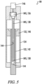
- Fig. 5 A representative construction of such a "smart" hydraulic cylinder is shown in Fig. 5 , and the details of a “smart” hydraulic suspension actuator 84 will be described by way of example.
- Fig. 5 may also be representative of the internal construction of any of the other actuators herein described when those actuators are implemented as “smart" cylinders.
- the actuator 84 includes an integrated sensor 84S configured to provide a signal corresponding to an extension of a piston member 132 relative to a cylinder member 134 of the actuator 84.
- the sensor 84S includes a position sensor electronics housing 136 and a position sensor coil element 138.
- the piston portion 132 of actuator 84 includes a piston 140 and a rod 142.
- the piston 140 and rod 142 have a bore 144 defined therein, within which is received the position sensor coil element 138.
- the actuator 84 is constructed such that a signal is provided at connector 146 representative of the position of the piston 140 relative to the position sensor coil element 138.
- Such smart cylinders may operate on several different physical principles. Examples of such smart cylinders include but are not limited to magneto-strictive sensing, magneto-resistive sensing, resistive (potentiometric) sensing, Hall effect sensing, sensing using linear variable differential transformers, and sensing using linear variable inductance transducers.
- the dowel bar inserter apparatus 40 includes a control system 200 including a controller 202.
- the controller 202 may be part of the machine control system of the slip form paver 10, or it may be a separate control module.
- the controller 202 may for example be mounted in a control panel 203 located at the operator's station 36.
- the controller 202 is configured to receive input signals from the various sensors.
- the signals transmitted from the various sensors to the controller 202 are schematically indicated in Fig. 7 by lines connecting the sensors to the controller with an arrowhead indicating the flow of the signal from the sensor to the controller 202.
- extension signals from the extension sensors such as 84S will be received so that the controller can monitor the extension of the suspension actuators such as 84.
- controller 202 will generate control signals for controlling the operation of the various actuators discussed above, which control signals are indicated schematically in Fig. 7 by lines connecting the controller 202 to graphic depictions of the various actuators with the arrow indicating the flow of the command signal from the controller 202 to the respective actuators. It will be understood that for control of a hydraulic cylinder type actuator the controller 202 will send an electrical signal to an electro/mechanical control valve (not shown) which controls flow of hydraulic fluid to and from the hydraulic cylinder.
- Fig. 7 schematically shows the adjustable height support actuator 106, the left insertion actuator 64, the left hydraulic chain tensioning cylinder 110, the left rear suspension actuator 84, one of the deflection compensation actuators 92, and the crown actuator 130.
- Controller 202 includes or may be associated with a processor 204, a computer readable medium 206, a data base 208 and an input/output module or control panel 210 having a display 212.
- An input/output device 214 such as a keyboard, joystick or other user interface, is provided so that the human operator may input instructions to the controller. It is understood that the controller 202 described herein may be a single controller having all of the described functionality, or it may include multiple controllers wherein the described functionality is distributed among the multiple controllers.
- Various operations, steps or algorithms as described in connection with the controller 202 can be embodied directly in hardware, in a computer program product 216 such as a software module executed by the processor 204, or in a combination of the two.
- the computer program product 216 can reside in RAM memory, flash memory, ROM memory, EPROM memory, EEPROM memory, registers, hard disk, a removable disk, or any other form of computer-readable medium 206 known in the art.
- An exemplary computer-readable medium 206 can be coupled to the processor 204 such that the processor can read information from, and write information to, the memory/ storage medium.
- the medium can be integral to the processor.
- the processor and the medium can reside in an application specific integrated circuit (ASIC).
- the ASIC can reside in a user terminal.
- the processor and the medium can reside as discrete components in a user terminal.
- processor may refer to at least general-purpose or specific-purpose processing devices and/or logic as may be understood by one of skill in the art, including but not limited to a microprocessor, a microcontroller, a state machine, and the like.
- a processor can also be implemented as a combination of computing devices, e.g., a combination of a DSP and a microprocessor, a plurality of microprocessors, one or more microprocessors in conjunction with a DSP core, or any other such configuration.
- controller 202 may be programmed to receive extension signals from each of the extension sensors of the various hydraulic smart cylinders and to send control signals to control the extension of those hydraulic smart cylinders at least in part in response to the respective extension signals.
- each of the suspension actuator extension sensors 84S, 86S, 88S and 90S may be configured to generate a suspension actuator extension signal corresponding to the amount of extension of the respective suspension actuator.
- the controller 202 may be configured to receive the suspension actuator extension signals to send control signals to the respective suspension actuators, at least in part in response to the suspension actuator extension signals for the respective suspension actuators.
- controller 202 may be configured to adjust the amount of extension of the forward suspension actuators 88 and 90 relative to the amount of extension of the rear suspension actuators 84 and 86 to adjust a front to rear slope of the bottom pan assembly 52.
- the forward edge of the bottom pan assembly is typically held slightly higher that the rear edge so as to prevent the accumulation of a ridge of concrete material in front of the bottom pan assembly 52 as the bottom pan assembly slides forward over the surface 18 of the freshly formed concrete slab 16.
- a swelling sensor 220 may be provided to detect such swelling.
- the swelling sensor 220 generates a swelling signal which is received by the controller 202.
- the controller 202 in response to the swelling signal, may send control signals to all of the suspension actuators 84, 86, 88 and 90 to raise the entire bottom pan assembly 52 and/or to adjust the front to rear slope of the bottom pan assembly 52 so as to accommodate the detected swelling.
- the control signals are at least in part in response to the signal from the swelling sensor 220.
- the swelling may be accommodated by an adjustment of the front to rear slope of the bottom pan assembly 52, but if a relatively large amount of swelling is detected the swelling may be accommodated by raising the entire bottom pan assembly 52 in addition to possibly adjusting the front to rear slope of the bottom pan assembly 52.
- the swelling sensor 220 may be a contactless distance sensor such as an ultrasonic sensor or a laser sensor supported from the bottom pan assembly 52 and directed toward the surface 18 of the concrete slab 16 ahead of the bottom pan assembly 52 to measure a vertical distance 221 from a fixed location on the bottom pan assembly to the surface 18. If the slab 16 ahead of the bottom pan assembly 52 begins to swell the distance measured by the swelling sensor 220 will decrease and corrective action can be taken to raise the bottom pan assembly 52 and/or to raise the forward edge of the bottom pan assembly 52 to increase the front to rear slope.
- a contactless distance sensor such as an ultrasonic sensor or a laser sensor supported from the bottom pan assembly 52 and directed toward the surface 18 of the concrete slab 16 ahead of the bottom pan assembly 52 to measure a vertical distance 221 from a fixed location on the bottom pan assembly to the surface 18.
- the swelling sensor 220 may be a contactless distance sensor such as an ultrasonic sensor or a laser sensor supported from the slip form paver mold 24 and directed toward the surface 18 of the concrete slab 16 behind of the slip form paver mold 24 to measure a vertical distance 223 from a fixed location on the mold 24 to the surface 18.
- Figs. 12A and 12B schematically show the relative positions of the slip form paver mold 24 and the dowel bar inserter 40 in the forwardmost relative position of the dowel bar inserter 40 (when the insertion step begins) and the rearwardmost position of the dowel bar inserter 40 (when the insertion step ends), respectively.
- the dowel bar inserter 40 slides forward and backward relative to slip form paver mold 24 on the rails 48 during the dowel bar insertion operation.
- the swelling sensor 220 mounted on the slip form paver mold 24 can monitor the extent of concrete swelling as the slip form paver mold 24 moves ahead relative to the dowel bar inserter 40, and then as the dowel bar inserter 40 moves forward over the swollen concrete the controller 202 can make appropriate adjustments in the suspension actuators 84, 86, 88 and 90 and the deflection compensation actuators 92 to accommodate the swelling.
- a still further alternative type of swelling sensor 220 may be a pressure sensor 220P placed in the concrete near the bottom of the concrete mold 24 at its forward edge as schematically illustrated in Figs. 12A and 12B .
- a pressure sensor 220P placed in the concrete near the bottom of the concrete mold 24 at its forward edge as schematically illustrated in Figs. 12A and 12B .
- vibrators not shown
- the mass of concrete is significantly liquified and behaves in large part like a liquid.
- the measure of pressure in the concrete by pressure sensor 220P may be used as an indicator of expected swelling.
- each of the deflection compensation actuators 92 may comprise a hydraulic smart cylinder 94 including an integral deflection compensation actuator extension sensor 92S configured to generate a deflection compensation actuator extension signal corresponding to the amount of extension of the respective deflection compensation actuator 92.
- the controller 202 may be configured to receive the deflection compensation actuator extension signals from the deflection compensation actuator extension sensors 92S, and to send control signals to hydraulic cylinders 94 of the respective deflection compensation actuators 92, at least in part in response to the deflection compensation actuator extension signals for the respective deflection compensation actuators 92.
- the deflection compensation actuators 92 may be adjusted simultaneously with the suspension actuators 84, 86, 88 and 90 to assist in the adjustment of front to rear slope of the bottom pan assembly 52 and/or to assist in height adjustment of the bottom pan assembly 52. Such adjustments of the deflection compensation actuators 92 may be at least in part in response to the signals from the swelling sensor 220 similar to that described above for the suspension actuators.
- controller 202 may be configured to have a transport mode in which all of the suspension actuators 84, 86, 88 and 90 and all of the deflection compensation actuators 92 are retracted in unison to raise the bottom pan assembly 52 to a transport position in which the bottom pan assembly 52 is located a substantial distance 91 above either the ground surface or the paving slab 16 as necessary.
- a transport position is schematically illustrated in Fig. 11 .
- the controller 202 may save the extension data for all of the suspension actuators 84, 86, 88 and 90 and for the deflection compensation actuators 92, thereby defining the vertical location of the bottom pan assembly 52 in engagement with the concrete slab 16. Then the bottom pan assembly may be raised above the slab 16 as in the transport mode. Then at the beginning of the next paving day the controller 202 may return the bottom pan assembly 52 to the exact same vertical position to resume paving. Similarly, any of the other actuators having associated extension sensors may be returned to their previous positions after any break in the paving operation.
- each of the chain tensioning actuators 110 may have associated therewith a chain tensioning sensor 124.
- the controller 202 may be configured to receive a chain tensioning signal from the chain tensioning sensor 124 and to send a control signal to the chain tensioning actuator 110, at least in part in response to the chain tension signal.
- the human operator may input or set a desired chain tension to the controller 202 via the input 214 and the controller 202 may control the chain tension to that set point.
Landscapes
- Engineering & Computer Science (AREA)
- Architecture (AREA)
- Civil Engineering (AREA)
- Structural Engineering (AREA)
- Mechanical Engineering (AREA)
- Road Paving Machines (AREA)
- On-Site Construction Work That Accompanies The Preparation And Application Of Concrete (AREA)
- Conveying And Assembling Of Building Elements In Situ (AREA)
Claims (17)
- Appareil introducteur de goujons destiné à introduire des goujons dans une dalle de béton récemment mise en place, l'appareil comprenant :des premier et second chariots d'extrémité (44, 46) ;un ensemble table de coffrage inférieur (52) configuré pour venir en contact avec une surface supérieure de la dalle de béton ;une poutre d'introduction (62) ;une pluralité de fourches d'introduction (78) fixées à la poutre d'introduction (62) ;des premier et second actionneurs d'introduction (64, 66) supportant la poutre d'introduction (62) à partir respectivement des premier et second chariots d'extrémité (44, 46) pour élever et abaisser la poutre d'introduction et les fourches d'introduction par rapport aux chariots d'extrémité ;au moins un actionneur de suspension de la première extrémité (84, 88) destiné à supporter l'ensemble table de coffrage inférieur (52) à partir du premier chariot d'extrémité indépendamment de l'élévation et de l'abaissement de la poutre d'introduction par rapport au premier chariot d'extrémité ;au moins un actionneur de suspension de la seconde extrémité (86, 90) destiné à supporter l'ensemble table de coffrage inférieur (52) à partir du second chariot d'extrémité indépendamment de l'élévation et de l'abaissement de la poutre d'introduction par rapport au second chariot d'extrémité ; etdans lequel chacun des actionneurs de suspension (84, 86, 88, 90) comprend, associé à ce dernier, capteur d'extension de l'actionneur de suspension(84S, 86S, 88S, 90S) configuré pour détecter une quantité d'extension de l'actionneur de suspension respectif.
- Appareil introducteur de goujons selon la revendication 1, dans lequel :l'au moins un actionneur de suspension de la première extrémité comprend un premier actionneur de suspension d'extrémité avant (84) et un premier actionneur de suspension d'extrémité arrière (88) ;l'au moins un actionneur de suspension de la seconde extrémité comprend un second actionneur de suspension d'extrémité avant (86) et un second actionneur de suspension d'extrémité arrière (90) ; etchacun des actionneurs de suspension (84, 86, 88, 90) comprend un vérin hydraulique intelligent, et le capteur de course d'actionneur de suspension (84S, 86S, 88S, 90S) associé à chaque actionneur de suspension fait partie intégrante du vérin hydraulique intelligent.
- Appareil introducteur de goujons selon la revendication 1 ou la revendication 2, comprenant en outre :
une pluralité d'actionneurs de compensation de fléchissement (92) configurés pour supporter une pluralité de positions intermédiaires de l'ensemble table de coffrage inférieur (52), les actionneurs de compensation de fléchissement (92) étant situés entre les premier et second actionneurs de suspension (84, 86, 88, 90). - Appareil introducteur de goujons selon la revendication 3, dans lequel :
chacun des actionneurs de compensation de fléchissement (92) comprend un vérin hydraulique (94) et un connecteur flexible (96) reliant le vérin hydraulique à l'ensemble table de coffrage inférieur (52) de sorte que les actionneurs de compensation de fléchissement (92) puissent supporter l'ensemble table de coffrage inférieur (52) du point de vue d'une charge de traction mais pas d'une charge de compression des connecteurs flexibles. - Appareil introducteur de goujons selon la revendication 4, dans lequel :
chacun des vérins hydrauliques (94) comprend un vérin hydraulique intelligent comprenant un capteur d'extension d'actionneur de compensation de fléchissement intégré (94S). - Appareil introducteur de goujons selon la revendication 3, dans lequel :chacun des actionneurs de compensation de fléchissement (92) est relié à la poutre d'introduction (62) de sorte que les positions de la pluralité de positions intermédiaires de l'ensemble table de coffrage inférieur (52) soient supportées à partir de la poutre d'introduction ;
ouchacun des actionneurs de compensation de fléchissement (92) est relié à une structure de support (95) fixée aux premier et second chariots d'extrémité de sorte que les positions de la pluralité de positions intermédiaires de l'ensemble table de coffrage inférieur (52) soient supportées à partir de la structure de support. - Appareil introducteur de goujons selon la revendication 1, dans lequel :chacun des capteurs d'extension d'actionneur de suspension (84S, 86S, 88S, 90S) est configuré pour générer un signal d'extension d'actionneur de suspension correspondant à la quantité d'extension de l'actionneur de suspension respectif (84, 86, 88, 90) ; etl'appareil comprend en outre :
un organe de commande (202) configuré pour recevoir les signaux d'extension d'actionneur de suspension et pour envoyer des signaux de commande aux actionneurs de suspension respectifs (84, 86, 88, 90), au moins en partie en réponse aux signaux d'extension d'actionneur de suspension des actionneurs de suspension respectifs. - Appareil introducteur de goujons selon la revendication 7, comprenant en outre :une pluralité d'actionneurs de compensation de fléchissement (92) configurés pour supporter une pluralité de positions intermédiaires de l'ensemble table de coffrage inférieur (52) à partir de la poutre d'introduction (62), chacun des actionneurs de compensation de fléchissement (92) comprenant un vérin hydraulique intelligent comprenant un capteur d'extension d'actionneur de compensation de fléchissement intégré (92S) ; etdans lequel l'organe de commande (202) est en outre configuré pour recevoir des signaux d'extensiond'actionneur de compensation de fléchissement en provenance des capteurs d'extension d'actionneur de compensation de fléchissement (92S) correspondant à une extension des actionneurs de compensation de fléchissement respectifs, et pour envoyer des signaux de commande aux actionneurs de compensation de fléchissement respectifs (92), au moins en partie en réponse aux signaux d'extension d'actionneur de compensation de fléchissement des actionneurs de compensation de fléchissement respectifs.
- Appareil introducteur de goujons selon la revendication 1, comprenant en outre :un convoyeur à chaîne (108) configuré pour transporter des goujons vers l'ensemble table de coffrage inférieur (52) ;un actionneur de tension de chaîne (110) configuré pour maintenir une certaine tension dans le convoyeur à chaîne (108) ;un capteur de tension de chaîne (124) ; etun organe de commande (202) configuré pour :recevoir un signal de tension de chaîne en provenance du capteur de tension de chaîne (124) ; etenvoyer un signal de commande à l'actionneur de tension de chaîne (110), au moins en partie en réponse au signal de tension de chaîne.
- Appareil introducteur de goujons selon la revendication 1, dans lequel :l'au moins un actionneur de suspension de la première extrémité comprend un premier actionneur de suspension d'extrémité avant (84) et un premier actionneur de suspension d'extrémité arrière (88) ; etl'au moins un actionneur de suspension de la seconde extrémité comprend un second actionneur de suspension d'extrémité avant (86) et un second actionneur de suspension d'extrémité arrière (90) ;dans lequel l'appareil introducteur de goujons comprend en outre un organe de commande (202) configuré pour régler la quantité d'extension du premier actionneur de suspension d'extrémité avant (84) et du second actionneur de suspension d'extrémité avant (88) par rapport à la quantité d'extension respectivement du premier actionneur de suspension d'extrémité arrière (86) et du second actionneur de suspension d'extrémité arrière (90) pour régler une pente de l'avant vers l'arrière de l'ensemble table de coffrage inférieur.
- Appareil introducteur de goujons selon la revendication 10, comprenant en outre :
une pluralité d'actionneurs de compensation de fléchissement (92) configurés pour supporter une pluralité de positions intermédiaires de l'ensemble table de coffrage inférieur (52), les actionneurs de compensation de fléchissement (92) étant situés entre les premier et second actionneurs de suspension (84, 86, 88, 90), les actionneurs de compensation de fléchissement (92) étant disposés par paire d'actionneurs de compensation de fléchissement, chaque paire comprenant un actionneur de compensation de fléchissement avant et un actionneur de compensation de fléchissement arrière ; et dans lequel l'organe de commande (202) est en outre configuré pour régler une quantité d'extension des actionneurs de compensation de fléchissement avant par rapport à une quantité d'extension des actionneurs de compensation de fléchissement arrière pour régler la pente de l'avant vers l'arrière de l'ensemble table de coffrage inférieur (52). - Appareil introducteur de goujons selon la revendication 10, comprenant en outre :un capteur de gonflement (220) configuré pour détecter un gonflement de la dalle de béton ; etdans lequel l'organe de commande (202) est configuré pour recevoir un signal en provenance du capteur de gonflement (220) correspondant au gonflement de la dalle de béton, et pour régler la pente de l'avant vers l'arrière de l'ensemble table de coffrage inférieur (52) au moins en partie en réponse au signal provenant du capteur de gonflement.
- Appareil introducteur de goujons selon la revendication 12, dans lequel :
l'organe de commande (202) est en outre configuré pour régler tous les actionneurs de suspension (84, 86, 88, 90) pour élever tout l'ensemble table de coffrage inférieur (52) au moins en partie en réponse au signal provenant du capteur de gonflement. - Appareil introducteur de goujons selon la revendication 1, comprenant en outre :
un organe de commande (202) configuré pour avoir un mode de transport dans lequel tous les actionneurs de suspension (84, 86, 88, 90) sont réglés pour élever l'ensemble table de coffrage inférieur (52) jusqu'à une position de transport. - Procédé de mise en œuvre d'un appareil introducteur de goujons selon la revendication 1, le procédé comprenant les étapes consistant à :recevoir des signaux d'extension d'actionneur de suspension en provenance des capteurs d'extension d'actionneur de suspension au moyen d'un organe de commande ; etenvoyer des signaux de commande de l'organe de commande aux actionneurs de suspension au moins en partie en réponse aux signaux d'extension d'actionneur de suspension des actionneurs de suspension respectifs.
- Procédé selon la revendication 15, dans lequel l'appareil comprend en outre une pluralité d'actionneurs de compensation de fléchissement configurés pour supporter une pluralité de positions intermédiaires de l'ensemble table de coffrage inférieur à partir de la poutre d'introduction, chacun des actionneurs de compensation de fléchissement comprenant un vérin hydraulique intelligent comprenant un capteur d'extension d'actionneur de compensation de fléchissement intégré, le procédé comprenant en outre les étapes consistant à :recevoir des signaux d'extension d'actionneur de compensation de fléchissement en provenance des capteurs d'extension d'actionneur de compensation de fléchissement correspondant à une extension des actionneurs de compensation de fléchissement respectifs ; etenvoyer des signaux de commande aux actionneurs de compensation de fléchissement respectifs, au moins en partie en réponse aux signaux d'extension d'actionneur de compensation de fléchissement des actionneurs de compensation de fléchissement respectifs.
- Procédé selon la revendication 15, comprenant en outre les étapes consistant à :détecter un gonflement de la dalle de béton au moyen d'un capteur de gonflement ;recevoir, au moyen de l'organe de commande, un signal provenant du capteur de gonflement correspondant au gonflement de la dalle de béton ; etenvoyer des signaux de commande à partir de l'organe de commande pour régler la pente de l'avant vers l'arrière de l'ensemble table de coffrage inférieur au moins en partie en réponse au signal provenant du capteur de gonflement.
Applications Claiming Priority (1)
| Application Number | Priority Date | Filing Date | Title |
|---|---|---|---|
| US17/555,568 US12203226B2 (en) | 2021-12-20 | 2021-12-20 | Dowel bar inserter |
Publications (3)
| Publication Number | Publication Date |
|---|---|
| EP4198202A1 EP4198202A1 (fr) | 2023-06-21 |
| EP4198202C0 EP4198202C0 (fr) | 2024-07-31 |
| EP4198202B1 true EP4198202B1 (fr) | 2024-07-31 |
Family
ID=84439762
Family Applications (2)
| Application Number | Title | Priority Date | Filing Date |
|---|---|---|---|
| EP22211870.5A Active EP4198202B1 (fr) | 2021-12-20 | 2022-12-07 | Appareil d'insertion de barre de goujon et procédé de fonctionnement dudit appareil d'insertion de barre de goujon |
| EP22838754.4A Active EP4453316B1 (fr) | 2021-12-20 | 2022-12-14 | Machine de pavage par coffrage glissant avec capteur de gonflement et procédé de commande d'une telle machine de pavage par coffrage glissant |
Family Applications After (1)
| Application Number | Title | Priority Date | Filing Date |
|---|---|---|---|
| EP22838754.4A Active EP4453316B1 (fr) | 2021-12-20 | 2022-12-14 | Machine de pavage par coffrage glissant avec capteur de gonflement et procédé de commande d'une telle machine de pavage par coffrage glissant |
Country Status (4)
| Country | Link |
|---|---|
| US (1) | US12203226B2 (fr) |
| EP (2) | EP4198202B1 (fr) |
| CN (3) | CN118434940A (fr) |
| WO (1) | WO2023117639A1 (fr) |
Families Citing this family (3)
| Publication number | Priority date | Publication date | Assignee | Title |
|---|---|---|---|---|
| WO2022041234A1 (fr) * | 2020-08-31 | 2022-03-03 | L'oreal | Compte-gouttes à régulation de dosage |
| US12203226B2 (en) * | 2021-12-20 | 2025-01-21 | Wirtgen Gmbh | Dowel bar inserter |
| CN119571730A (zh) * | 2024-12-05 | 2025-03-07 | 中交二公局第一工程有限公司 | 一种激光超声波双系统摊铺机及摊铺施工方法 |
Family Cites Families (45)
| Publication number | Priority date | Publication date | Assignee | Title |
|---|---|---|---|---|
| US3605579A (en) | 1968-12-11 | 1971-09-20 | Carl J Heltzel | Anti-skid surface texturing and groove forming equipment for use in concrete roads |
| FR2209009B1 (fr) | 1972-08-22 | 1975-01-03 | Screg | |
| US4493584A (en) * | 1981-12-17 | 1985-01-15 | Guntert & Zimmerman Const. Div., Inc. | Apparatus and process for dowel insertions |
| CH669232A5 (de) * | 1986-03-27 | 1989-02-28 | Thoma Werksvertretungen | Vorrichtung zum einbringen von bewehrungsstaeben in eine fahrbahndecke aus beton. |
| US5101360A (en) | 1990-04-16 | 1992-03-31 | Gomaco Corporation | Method and apparatus for automatically adjusting the crown height for a slip forming paver |
| US5190397A (en) * | 1991-03-18 | 1993-03-02 | Gomaco Corporation | Dowel bar insertion method and apparatus for concrete paving machine |
| US5209602A (en) | 1991-06-10 | 1993-05-11 | Gomaco Corporation | Method and apparatus for inserting dowel bars for a concrete slip forming machine |
| US5318377A (en) * | 1992-06-18 | 1994-06-07 | Cmi Corporation | Paving machine with midline dowel bar insertion |
| US5405212A (en) | 1992-06-18 | 1995-04-11 | Cmi Corporation | Paving machine with drop-then-stop dowel bar insertion |
| US5529434A (en) * | 1993-04-08 | 1996-06-25 | Swisher, Jr.; George W. | Paving material machine having hopper capacity and compensating tunnel capacity |
| AU1832795A (en) * | 1994-01-21 | 1995-08-08 | George W. Swisher Jr. | Paving material machine having a tunnel with automatic gate control |
| US5568992A (en) | 1995-05-19 | 1996-10-29 | Caterpillar Paving Products Inc. | Screed control system for an asphalt paver and method of use |
| CA2211331C (fr) | 1996-08-13 | 2002-05-28 | Gary L. Godbersen | Installation pour inserer des barres d'armature dans un moule de machine pour le moulage continu de dalles de beton |
| US6099204A (en) * | 1996-08-13 | 2000-08-08 | Godbersen; Gary L. | Apparatus for inserting dowel bars in a concrete slip forming machine |
| BE1011454A6 (nl) * | 1997-09-16 | 1999-09-07 | Casters Francois | Betonneermachine en deuvelapparaat hierbij aangewend. |
| US5991225A (en) | 1998-02-27 | 1999-11-23 | Micron Technology, Inc. | Programmable memory address decode array with vertical transistors |
| DE19904797C1 (de) | 1999-02-05 | 2000-12-28 | Wirtgen Gmbh | Vorrichtung zum Einbringen von Dübeln in frisch verlegte Fahrbahndecken |
| US6390726B1 (en) * | 1999-10-01 | 2002-05-21 | Guntert & Zimmerman Const. Div. | Dowel bar inserter kit having chain feeder |
| US6176643B1 (en) | 1999-10-01 | 2001-01-23 | Guntert & Zimmerman Const. Div. | Detachable dowel bar inserter kit for portable slip form paver |
| BE1014342A3 (nl) | 2001-08-13 | 2003-09-02 | Drion Constructie Bvba | Werkwijze en machine voor het vormen van een betonbaan of dergelijke, alsmede inrichting voor het inbrengen van deuvels hierbij aangewend. |
| US6655689B1 (en) | 2002-02-28 | 2003-12-02 | Perry B. Stasi | Craps game improvement |
| US7136522B2 (en) | 2002-10-09 | 2006-11-14 | Xerox Corporation | Systems for spectral multiplexing of source images to provide a composite image, for rendering the composite image, and for spectral demultiplexing of the composite image to animate recovered source images |
| US7316522B2 (en) | 2005-03-10 | 2008-01-08 | Guntert & Zimmerman Const. Div., Inc. | Concrete placer/spreader having roll in/roll out conveyor |
| CN2786190Y (zh) * | 2005-04-29 | 2006-06-07 | 长沙理工大学 | 一种独立施工的悬挂式水泥混凝土路面纵向传力杆压入机 |
| EP2199466B1 (fr) | 2008-12-16 | 2011-07-13 | Joseph Vögele AG | Procédé destiné à l'insertion d'un revêtement de chaussée |
| US8382396B2 (en) | 2009-09-09 | 2013-02-26 | Guntert & Zimmerman Const. Div., Inc. | Paver having dowel bar inserter with automated dowel bar feeder |
| DE102009059106A1 (de) | 2009-12-18 | 2011-06-22 | Wirtgen GmbH, 53578 | Selbstfahrende Baumaschine und Verfahren zur Steuerung einer selbstfahrenden Baumaschine |
| US8989968B2 (en) | 2012-10-12 | 2015-03-24 | Wirtgen Gmbh | Self-propelled civil engineering machine system with field rover |
| US9051696B1 (en) | 2013-02-04 | 2015-06-09 | Gomaco Corporation | Modular configurable paving apparatus and modular configurable paving operation system |
| US9096977B2 (en) | 2013-05-23 | 2015-08-04 | Wirtgen Gmbh | Milling machine with location indicator system |
| US9395726B1 (en) | 2014-07-24 | 2016-07-19 | Google Inc. | Methods and devices for bound and gallop gaits |
| US9428869B2 (en) | 2014-10-24 | 2016-08-30 | Gomaco Corporation | Adjustable width trail paver |
| US9551115B2 (en) | 2014-12-19 | 2017-01-24 | Wirtgen Gmbh | Transition on the fly |
| US9631329B2 (en) | 2014-12-19 | 2017-04-25 | Wirtgen Gmbh | Frame distortion control |
| US10132046B2 (en) | 2015-04-20 | 2018-11-20 | Wirtgen Gmbh | Concrete texturing machine |
| US20170073907A1 (en) * | 2015-09-10 | 2017-03-16 | Caterpillar Paving Products Inc. | Screed cushioning system and method |
| US10253461B2 (en) | 2016-12-07 | 2019-04-09 | Wirtgen Gmbh | Variable width automatic transition |
| US10738421B2 (en) * | 2017-12-29 | 2020-08-11 | Guntert & Zimmerman Const. Div., Inc. | Extended width dowel bar inserter |
| US10982396B2 (en) | 2019-07-11 | 2021-04-20 | Wirtgen Gmbh | Slip form paver |
| US11339541B2 (en) | 2019-12-05 | 2022-05-24 | Wirtgen Gmbh | Adjustable width mold |
| US11162233B2 (en) | 2019-12-05 | 2021-11-02 | Wirtgen Gmbh | Adjustable width mold |
| US11085154B2 (en) | 2019-12-30 | 2021-08-10 | Wirtgen Gmbh | Adjustable wear sole |
| US11473250B2 (en) | 2020-01-21 | 2022-10-18 | Wirtgen Gmbh | Placer spreader with adjustable strike off |
| CN111549629A (zh) * | 2020-04-28 | 2020-08-18 | 中国一冶集团有限公司 | 一种便捷式砼路面传力杆安装器及传力杆安装方法 |
| US12203226B2 (en) * | 2021-12-20 | 2025-01-21 | Wirtgen Gmbh | Dowel bar inserter |
-
2021
- 2021-12-20 US US17/555,568 patent/US12203226B2/en active Active
-
2022
- 2022-12-07 EP EP22211870.5A patent/EP4198202B1/fr active Active
- 2022-12-14 EP EP22838754.4A patent/EP4453316B1/fr active Active
- 2022-12-14 CN CN202280084869.1A patent/CN118434940A/zh active Pending
- 2022-12-14 WO PCT/EP2022/085911 patent/WO2023117639A1/fr not_active Ceased
- 2022-12-20 CN CN202211644233.6A patent/CN116290835A/zh active Pending
- 2022-12-20 CN CN202223432133.5U patent/CN219431414U/zh active Active
Also Published As
| Publication number | Publication date |
|---|---|
| EP4198202C0 (fr) | 2024-07-31 |
| CN118434940A (zh) | 2024-08-02 |
| US12203226B2 (en) | 2025-01-21 |
| EP4453316C0 (fr) | 2025-08-27 |
| CN219431414U (zh) | 2023-07-28 |
| EP4453316B1 (fr) | 2025-08-27 |
| US20230193570A1 (en) | 2023-06-22 |
| EP4198202A1 (fr) | 2023-06-21 |
| CN116290835A (zh) | 2023-06-23 |
| WO2023117639A1 (fr) | 2023-06-29 |
| EP4453316A1 (fr) | 2024-10-30 |
Similar Documents
| Publication | Publication Date | Title |
|---|---|---|
| EP4198202A1 (fr) | Appareil d'insertion de barre de goujon et procédé de fonctionnement dudit appareil d'insertion de barre de goujon | |
| EP3763877B1 (fr) | Finisseur à coffrage glissant | |
| EP3034697B1 (fr) | Machine de construction et procédé de fonctionnement d'une machine de construction | |
| EP3674483B1 (fr) | Finisseur à coffrages glissants | |
| DE2131650A1 (de) | Strassenbaumaschine und Steuerungen dafuer | |
| EP4386141B1 (fr) | Machine à coffrage glissant et procédé de commande d'une machine à coffrage glissant | |
| US20250012022A1 (en) | Slip Form Paving Machine with A Swelling Sensor and Method of Controlling Such Slip Form Paving Machine | |
| CN112878147A (zh) | 具有能够调节的刮除器的砂料撒布器 | |
| EP4249679A1 (fr) | Finisseuse de forme coulissante avec moule suspendu à largeur réglable | |
| CN113005859B (zh) | 可变高度的模具 | |
| EP4502273B1 (fr) | Machine de pavage à coffrage glissant et procédé de fonctionnement d'une machine de pavage à coffrage glissant | |
| US11421389B2 (en) | Variable height mold | |
| CN115506207A (zh) | 自动调零整平板组件 | |
| EP4386140B1 (fr) | Machine à coffrage glissant et procédé de commande d'une machine à coffrage glissant | |
| EP4386139A1 (fr) | Machine de pavage à coffrage glissant et procédé de fonctionnement d'une machine de pavage à coffrage glissant |
Legal Events
| Date | Code | Title | Description |
|---|---|---|---|
| PUAI | Public reference made under article 153(3) epc to a published international application that has entered the european phase |
Free format text: ORIGINAL CODE: 0009012 |
|
| STAA | Information on the status of an ep patent application or granted ep patent |
Free format text: STATUS: THE APPLICATION HAS BEEN PUBLISHED |
|
| AK | Designated contracting states |
Kind code of ref document: A1 Designated state(s): AL AT BE BG CH CY CZ DE DK EE ES FI FR GB GR HR HU IE IS IT LI LT LU LV MC ME MK MT NL NO PL PT RO RS SE SI SK SM TR |
|
| STAA | Information on the status of an ep patent application or granted ep patent |
Free format text: STATUS: REQUEST FOR EXAMINATION WAS MADE |
|
| 17P | Request for examination filed |
Effective date: 20231220 |
|
| RBV | Designated contracting states (corrected) |
Designated state(s): AL AT BE BG CH CY CZ DE DK EE ES FI FR GB GR HR HU IE IS IT LI LT LU LV MC ME MK MT NL NO PL PT RO RS SE SI SK SM TR |
|
| GRAP | Despatch of communication of intention to grant a patent |
Free format text: ORIGINAL CODE: EPIDOSNIGR1 |
|
| STAA | Information on the status of an ep patent application or granted ep patent |
Free format text: STATUS: GRANT OF PATENT IS INTENDED |
|
| RIC1 | Information provided on ipc code assigned before grant |
Ipc: E01C 19/48 20060101ALI20240307BHEP Ipc: E01C 11/14 20060101ALI20240307BHEP Ipc: E01C 23/04 20060101AFI20240307BHEP |
|
| INTG | Intention to grant announced |
Effective date: 20240327 |
|
| GRAS | Grant fee paid |
Free format text: ORIGINAL CODE: EPIDOSNIGR3 |
|
| GRAA | (expected) grant |
Free format text: ORIGINAL CODE: 0009210 |
|
| STAA | Information on the status of an ep patent application or granted ep patent |
Free format text: STATUS: THE PATENT HAS BEEN GRANTED |
|
| AK | Designated contracting states |
Kind code of ref document: B1 Designated state(s): AL AT BE BG CH CY CZ DE DK EE ES FI FR GB GR HR HU IE IS IT LI LT LU LV MC ME MK MT NL NO PL PT RO RS SE SI SK SM TR |
|
| REG | Reference to a national code |
Ref country code: CH Ref legal event code: EP Ref country code: GB Ref legal event code: FG4D |
|
| REG | Reference to a national code |
Ref country code: DE Ref legal event code: R096 Ref document number: 602022004982 Country of ref document: DE |
|
| REG | Reference to a national code |
Ref country code: IE Ref legal event code: FG4D |
|
| U01 | Request for unitary effect filed |
Effective date: 20240822 |
|
| U07 | Unitary effect registered |
Designated state(s): AT BE BG DE DK EE FI FR IT LT LU LV MT NL PT RO SE SI Effective date: 20240902 |
|
| PG25 | Lapsed in a contracting state [announced via postgrant information from national office to epo] |
Ref country code: NO Free format text: LAPSE BECAUSE OF FAILURE TO SUBMIT A TRANSLATION OF THE DESCRIPTION OR TO PAY THE FEE WITHIN THE PRESCRIBED TIME-LIMIT Effective date: 20241031 |
|
| PG25 | Lapsed in a contracting state [announced via postgrant information from national office to epo] |
Ref country code: GR Free format text: LAPSE BECAUSE OF FAILURE TO SUBMIT A TRANSLATION OF THE DESCRIPTION OR TO PAY THE FEE WITHIN THE PRESCRIBED TIME-LIMIT Effective date: 20241101 Ref country code: PL Free format text: LAPSE BECAUSE OF FAILURE TO SUBMIT A TRANSLATION OF THE DESCRIPTION OR TO PAY THE FEE WITHIN THE PRESCRIBED TIME-LIMIT Effective date: 20240731 |
|
| U20 | Renewal fee for the european patent with unitary effect paid |
Year of fee payment: 3 Effective date: 20241219 |
|
| PG25 | Lapsed in a contracting state [announced via postgrant information from national office to epo] |
Ref country code: IS Free format text: LAPSE BECAUSE OF FAILURE TO SUBMIT A TRANSLATION OF THE DESCRIPTION OR TO PAY THE FEE WITHIN THE PRESCRIBED TIME-LIMIT Effective date: 20241130 |
|
| PG25 | Lapsed in a contracting state [announced via postgrant information from national office to epo] |
Ref country code: HR Free format text: LAPSE BECAUSE OF FAILURE TO SUBMIT A TRANSLATION OF THE DESCRIPTION OR TO PAY THE FEE WITHIN THE PRESCRIBED TIME-LIMIT Effective date: 20240731 |
|
| PG25 | Lapsed in a contracting state [announced via postgrant information from national office to epo] |
Ref country code: RS Free format text: LAPSE BECAUSE OF FAILURE TO SUBMIT A TRANSLATION OF THE DESCRIPTION OR TO PAY THE FEE WITHIN THE PRESCRIBED TIME-LIMIT Effective date: 20241031 Ref country code: ES Free format text: LAPSE BECAUSE OF FAILURE TO SUBMIT A TRANSLATION OF THE DESCRIPTION OR TO PAY THE FEE WITHIN THE PRESCRIBED TIME-LIMIT Effective date: 20240731 |
|
| PG25 | Lapsed in a contracting state [announced via postgrant information from national office to epo] |
Ref country code: RS Free format text: LAPSE BECAUSE OF FAILURE TO SUBMIT A TRANSLATION OF THE DESCRIPTION OR TO PAY THE FEE WITHIN THE PRESCRIBED TIME-LIMIT Effective date: 20241031 Ref country code: PL Free format text: LAPSE BECAUSE OF FAILURE TO SUBMIT A TRANSLATION OF THE DESCRIPTION OR TO PAY THE FEE WITHIN THE PRESCRIBED TIME-LIMIT Effective date: 20240731 Ref country code: NO Free format text: LAPSE BECAUSE OF FAILURE TO SUBMIT A TRANSLATION OF THE DESCRIPTION OR TO PAY THE FEE WITHIN THE PRESCRIBED TIME-LIMIT Effective date: 20241031 Ref country code: IS Free format text: LAPSE BECAUSE OF FAILURE TO SUBMIT A TRANSLATION OF THE DESCRIPTION OR TO PAY THE FEE WITHIN THE PRESCRIBED TIME-LIMIT Effective date: 20241130 Ref country code: HR Free format text: LAPSE BECAUSE OF FAILURE TO SUBMIT A TRANSLATION OF THE DESCRIPTION OR TO PAY THE FEE WITHIN THE PRESCRIBED TIME-LIMIT Effective date: 20240731 Ref country code: GR Free format text: LAPSE BECAUSE OF FAILURE TO SUBMIT A TRANSLATION OF THE DESCRIPTION OR TO PAY THE FEE WITHIN THE PRESCRIBED TIME-LIMIT Effective date: 20241101 Ref country code: ES Free format text: LAPSE BECAUSE OF FAILURE TO SUBMIT A TRANSLATION OF THE DESCRIPTION OR TO PAY THE FEE WITHIN THE PRESCRIBED TIME-LIMIT Effective date: 20240731 |
|
| PG25 | Lapsed in a contracting state [announced via postgrant information from national office to epo] |
Ref country code: SM Free format text: LAPSE BECAUSE OF FAILURE TO SUBMIT A TRANSLATION OF THE DESCRIPTION OR TO PAY THE FEE WITHIN THE PRESCRIBED TIME-LIMIT Effective date: 20240731 |
|
| PG25 | Lapsed in a contracting state [announced via postgrant information from national office to epo] |
Ref country code: CZ Free format text: LAPSE BECAUSE OF FAILURE TO SUBMIT A TRANSLATION OF THE DESCRIPTION OR TO PAY THE FEE WITHIN THE PRESCRIBED TIME-LIMIT Effective date: 20240731 |
|
| PG25 | Lapsed in a contracting state [announced via postgrant information from national office to epo] |
Ref country code: SK Free format text: LAPSE BECAUSE OF FAILURE TO SUBMIT A TRANSLATION OF THE DESCRIPTION OR TO PAY THE FEE WITHIN THE PRESCRIBED TIME-LIMIT Effective date: 20240731 |
|
| PLBE | No opposition filed within time limit |
Free format text: ORIGINAL CODE: 0009261 |
|
| STAA | Information on the status of an ep patent application or granted ep patent |
Free format text: STATUS: NO OPPOSITION FILED WITHIN TIME LIMIT |
|
| PG25 | Lapsed in a contracting state [announced via postgrant information from national office to epo] |
Ref country code: MC Free format text: LAPSE BECAUSE OF FAILURE TO SUBMIT A TRANSLATION OF THE DESCRIPTION OR TO PAY THE FEE WITHIN THE PRESCRIBED TIME-LIMIT Effective date: 20240731 |
|
| 26N | No opposition filed |
Effective date: 20250501 |
|
| PG25 | Lapsed in a contracting state [announced via postgrant information from national office to epo] |
Ref country code: IE Free format text: LAPSE BECAUSE OF NON-PAYMENT OF DUE FEES Effective date: 20241207 |
|
| U20 | Renewal fee for the european patent with unitary effect paid |
Year of fee payment: 4 Effective date: 20251222 |
|
| PG25 | Lapsed in a contracting state [announced via postgrant information from national office to epo] |
Ref country code: CY Free format text: LAPSE BECAUSE OF FAILURE TO SUBMIT A TRANSLATION OF THE DESCRIPTION OR TO PAY THE FEE WITHIN THE PRESCRIBED TIME-LIMIT; INVALID AB INITIO Effective date: 20221207 |