EP4198218A1 - Recouvrement pour un mur - Google Patents
Recouvrement pour un mur Download PDFInfo
- Publication number
- EP4198218A1 EP4198218A1 EP21215235.9A EP21215235A EP4198218A1 EP 4198218 A1 EP4198218 A1 EP 4198218A1 EP 21215235 A EP21215235 A EP 21215235A EP 4198218 A1 EP4198218 A1 EP 4198218A1
- Authority
- EP
- European Patent Office
- Prior art keywords
- profile
- leg
- cover
- base plate
- fastening
- Prior art date
- Legal status (The legal status is an assumption and is not a legal conclusion. Google has not performed a legal analysis and makes no representation as to the accuracy of the status listed.)
- Withdrawn
Links
Images





Classifications
-
- E—FIXED CONSTRUCTIONS
- E04—BUILDING
- E04D—ROOF COVERINGS; SKY-LIGHTS; GUTTERS; ROOF-WORKING TOOLS
- E04D3/00—Roof covering by making use of flat or curved slabs or stiff sheets
- E04D3/40—Slabs or sheets locally modified for auxiliary purposes, e.g. for resting on walls, for serving as guttering; Elements for particular purposes, e.g. ridge elements, specially designed for use in conjunction with slabs or sheets
- E04D3/405—Wall copings
Definitions
- the present invention relates to a cover for a wall, for example a wall, masonry, a parapet or an attic.
- Wall covers are used to protect the wall from moisture and to drain moisture away.
- the covers can be formed from cover stones or metal cover elements, for example.
- measures must be taken between the adjacent cover elements to prevent waterlogging in the interfaces.
- the assembly of the cover is complex and error-prone.
- a cover for masonry comprising: a cover module with a head limb and laterally arranged side limbs.
- a fastening profile for fastening the cover is firmly connected to one end of the cover module.
- a protective channel for removing moisture is connected to the cover module at an end of the cover module opposite the fastening profile.
- the fastening profile is designed and arranged in such a way that a protective groove of a further cover module can be inserted between the fastening profile and the head piece to connect the cover modules to one another.
- the invention is based on the object of providing a cover for a wall that enables simple assembly that is less prone to errors.
- a cover for a wall comprising: a cover profile with a head limb and side limbs arranged laterally of the head limb; a fastening profile for fastening the cover to the wall; and a protective profile to wick away moisture; the fastening profile being connected to the cover profile at a first end thereof; and the protective profile is connected to the cover profile at a second end of the cover profile opposite the first end; and the fastening profile is designed and arranged in such a way that a protective profile of a further cover profile can be inserted between the fastening profile and the head piece in order to connect the cover profiles to one another, the fastening profile and the cover profile being braced against one another via a first spring element; and/or the protective profile and the cover profile are braced against one another via a second spring element.
- the first spring element can be designed as a resilient tab section of the fastening profile.
- the second spring element can be designed as a resilient tab section of the protective profile.
- the fastening profile and the cover profile can be braced against one another via a plurality of first spring elements.
- the protective profile and the cover profile can be braced against one another via a plurality of second spring elements.
- the fastening profile can have a base plate for fastening the cover to a wall.
- a first transition leg inclined relative to the base plate can be connected to a first side of the base plate.
- a second transition leg inclined relative to the base plate can connect to a second side of the base plate opposite the first side.
- a connection leg can be connected to the first transition leg.
- a support leg can connect to the second transition leg.
- a base plate plane spanned by the base plate and a connecting limb plane spanned by the connecting leg can be arranged parallel and at a distance from one another.
- the base plate can be connected to a bearing element, the bearing element comprising a bearing surface for bearing on the wall and a bearing plane spanned by the bearing surface being arranged transversely to the plane of the base plate.
- the support element can be designed integrally with the base plate.
- the support element can in particular be a shaped, for example a bent, section of the base plate. Alternatively, the support element can be welded or soldered to the base plate.
- the support element is connected to the base plate with connecting elements, for example screws, with the base plate also being able to be connected to the wall via these connecting elements in particular.
- the head leg and the connecting leg can be arranged at least partially at a distance from one another.
- a seal can be arranged between the head leg and the connecting leg.
- an adhesive can be provided between the head leg and the connecting leg, which glue connects the head leg and the connecting leg to one another.
- the seal can be formed by the adhesive.
- the protective profile can have a base plate.
- a first spacer leg can be connected to a first side of the base plate.
- a second spacer leg can be connected to a second side of the base plate opposite the first side.
- the protective profile can include one or more third spring elements.
- the protective profile can be clamped to the further cover profile via the one third spring element or the plurality of third spring elements.
- the head leg and the base plate of the protective profile can be arranged at least partially at a distance from one another.
- a seal can be arranged between the head leg and the base plate of the protective profile.
- the Head leg and the base plate of the protective profile can be provided with an adhesive that connects the head leg and the base plate of the protective profile.
- the seal can be formed by the adhesive.
- a first side limb can adjoin a first side of the head limb.
- a second side leg can be attached to a second side of the head leg opposite the first side.
- first side leg and the second side leg can have an engagement groove at their respective free end.
- the engagement groove of the first side leg can be designed as a beading of the first side leg.
- the engagement groove of the first side leg can be designed in such a way that a first section of the first side leg and a second section of the first side leg enclose an obtuse, right or acute angle.
- the engagement groove of the second side leg can be designed as a flanged portion of the second side leg.
- the engagement groove of the second side leg can be designed in such a way that a first section of the second side leg and a second section of the second side leg enclose an obtuse, right or acute angle.
- the first spacer leg of the fastening profile can engage in the engagement groove of the first side leg.
- the second spacer leg of the fastening profile can engage in the engagement groove of the second side leg.
- the first spacer leg of the protective profile can engage in the engagement groove of the first side leg.
- the second spacer leg of the protective profile can engage in the engagement groove of the second side leg.
- first side leg and the first spacer leg of the fastening profile can be arranged at least partially at a distance from one another.
- a seal can be arranged between the first side leg and the first spacer leg of the fastening profile.
- an adhesive can be provided between the first side leg and the first spacer leg of the fastening profile connects the first side leg and the first spacer leg to one another.
- the seal can be formed by the adhesive.
- the second side leg and the second spacer leg of the fastening profile can be arranged at least partially at a distance from one another.
- a seal can be arranged between the second side leg and the second spacer leg of the fastening profile.
- an adhesive can be provided between the second side leg and the second spacer leg of the fastening profile, which adhesive connects the second side leg and the second spacer leg of the fastening profile to one another.
- the seal can be formed by the adhesive.
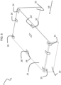
- the cover assembly 1 comprises a first cover 2 and a second cover 2' connected to each other.
- the first cover 2 and the second cover 2' are designed identically in the present case.
- the basic structure of the two covers 2, 2' is explained below with reference to the first cover 2.
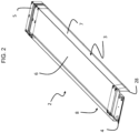
- the first cover 2 comprises a cover profile 3, which has a head limb 6, from which a first side limb 7 and a second side limb 8 extend on the opposite longitudinal sides.
- the head piece 6 is flat.
- the first side leg 7 and the second side leg 8 extend transversely to the head leg 6, the second side leg 8 having a greater extent than the first side leg 7.
- the first side leg 7 encloses an obtuse angle with the head leg 6.
- the second side leg 8 encloses an acute angle with the head leg 6 .
- the first side limb 7 and the second side limb 8 have an engagement groove 27 , 28 on their respective ends facing away from the head limb 6 .
- the engagement groove 27 of the first side leg 7 is designed as a flanging of the first side leg 7 .
- a section of the first side leg 7 is bent at a right angle to the rest of the first side leg 7 .
- the engagement groove 28 of the second side leg 8 is designed as a flanging of the second side leg 8 .
- a section of the second side leg 8 is bent at an acute angle to the rest of the second side leg 8 .
- the fastening profile 4 comprises a base plate 9, of which on a first side, which can also be referred to as the first end, a first transition leg 10 and on a second side opposite the first side, which can also be referred to as the second end, a second Transition leg 11 extends.
- the first transition leg 10 and the second transition leg 11 are each arranged transversely to the base plate 9 and have a rectangular shape.
- a connecting leg 12 connects to the first transition leg 10 .
- the connecting leg 12 also has a substantially rectangular shape.
- the connecting leg 12 spans a connecting leg plane which is arranged parallel to a base plate plane spanned by the base plate 9 .
- the plane of the connecting limbs and the plane of the base plate are arranged at a distance from one another, with the distance between the plane of the connecting limbs and the plane of the base plate being bridged by the first transition limb 10 .
- a first spacer leg 17 extends from the connecting leg 12 on a first side, which is arranged transversely to the first side of the base plate .
- the first and second spacer legs 17, 18 each have a substantially rectangular shape.
- the connecting leg 12 includes four spring elements 19, each of which is designed as an angled resilient tab section. One end of the spring elements 19 is connected to the connecting leg 12 .
- the spring elements 19 are essentially arranged in an opening 20 of the connecting leg 12 which extends from the connecting leg 12 into the first spacer leg 17 or into the second spacer leg 18 . In the unloaded state, the spring elements 19 are arranged in such a way that part of the tab section protrudes from the connecting leg 12 by the amount D1.
- a support leg 13 connects to the second transition leg 11 .
- the support leg 13 is in the assembled state of the cover assembly 1 on the Head leg 6 of the cover profile 3 of the second cover 2' or is connected to it via a seal or an adhesive.
- the support leg 13 also has an essentially rectangular shape.
- the support leg 13 spans a support leg plane which is arranged parallel to the base plate plane spanned by the base plate 9 and the connecting limb plane spanned by the connecting leg 12 .
- the plane of the supporting limbs and the plane of the base plate are arranged at a distance from one another, with the distance between the plane of the supporting limbs and the plane of the base plate being bridged by the second transition limb 11 .
- the distance between the supporting leg plane and the base plate plane and the distance between the connecting leg plane and the base plate plane are identical in the present case.
- the plane of the support leg thus lies in the plane of the connection leg and vice versa.
- the distance between the plane of the supporting limb and the plane of the base plate and the distance between the plane of the connecting limb and the plane of the base plate are designed differently.
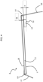
- the base plate 9 of the fastening profile 4 is connected to two support elements 14 .
- the support elements 14 are trapezoidal sections of the base plate 9, which are separated from the base plate 9 on three sides.
- the support elements 14 are bent over on the fourth side of the trapezium and are oriented essentially at right angles to the plane of the base plate. By bending over the support elements 14 an opening 15 is formed in the base plate 9 for each support element 14 .
- the support elements 14 have a support surface 16 which is arranged on an end pointing away from the base plate 9 and can be brought into contact with the wall.
- the bearing surface 16 is arranged transversely to the plane of the base plate.
- the bearing surface 16 and the plane of the base plate enclose an angle ⁇ . It can thus be ensured that the fastening profile 4 or the entire cover 2 can be fastened to the wall at an angle, so that moisture can run off the cover 2 and waterlogging can be avoided.
- the base plate 9 has three bores 25 through which the connecting means can be passed.
- a protective profile 5 is connected to the cover profile 3 on a second short side of the cover profile 3, which can also be referred to as the second transverse side.
- the protective profile 5 comprises a base plate 21, of which on a first side, which can also be referred to as the first end, a first spacer leg 22 and on a second side opposite the first side, which can also be referred to as the second end, a second Spacer leg 23 extends.
- the base plate 21 comprises six spring elements 24, 24', which are arranged in two rows of three spring elements each.
- the protective profile 5 can be braced with the cover profile 3 of the first cover 2 via the six spring elements 24, 24'.
- the four spring elements 24 are each designed as angled resilient tab sections.
- the spring elements 24 are connected to the base plate 21 at one end.
- the spring elements 24 are essentially arranged in an opening 31 which extends from the base plate 21 into the first spacer leg 22 or into the second spacer leg 23 .
- the two spring elements 24 ′ are each designed as straight, resilient tab sections which are arranged in an opening 32 in the base plate 21 .
- the base plate 21 comprises three spring elements 26, 26' which are arranged in a row.
- the protective profile 5 can be braced with a further cover profile 3 via the three spring elements 26, 26'.
- the two spring elements 26 are each designed as angled resilient tab sections.
- the spring elements 26 are connected to the base plate 21 at one end.
- the spring elements 26 are essentially arranged in an opening 33 which extends from the base plate 21 into the first spacer leg 22 or into the second spacer leg 23 .
- the spring element 26 ′ is designed as a straight, resilient tab section which is arranged in an opening 34 in the base plate 21 .
- the spring elements 24, 26 designed as angled resilient tab sections are arranged in the unloaded state in such a way that at least part of the tab section protrudes from the base plate 21 by the amount D2.
- the amount D2 can be the same as or different from the amount D1.
- the spring elements 24', 26' designed as a straight resilient tab section are arranged in the unloaded state in such a way that at least part of the tab section protrudes from the base plate 21 by the amount D3.
- the amount D3 can be the same as or different from the amounts D1 and/or D2.
- a fastening profile 4 sits in the cover profile 3 of the first cover 2 and is connected to it.
- the first spacer arm 17 engages in the engagement groove 27 of the first side arm 7
- the second spacer arm 18 engages in the engagement groove 28 of the second side arm 8 .
- the spring elements 19 of the fastening profile 4 are under resilient load in contact with the head leg 6 of the cover profile 3. The fastening profile 4 and the cover profile 3 are thus clamped together, so that there is a releasable frictional connection between the fastening profile 4 and the cover profile 3.
- An adhesive bond is provided between the cover profile 3 and the fastening profile 4, which extends completely or partially from the engagement groove 27 of the first side leg 7 via the first spacer leg 17, the connecting leg 12 and the second spacer leg 18 to the engagement groove 27 of the second side leg 8 .
- the bond extends over the connecting leg 12. The bond thus forms a seal 29 between the cover profile 3 and the fastening profile 4.
- the support leg 13 of the fastening profile 4 and the head leg 6 of the cover profile 3 of the second cover 2' are connected to one another by means of an adhesive.
- the protective profile 5 of the second cover 2' sits in the cover profile 3 of the second cover 2' and is connected to it.
- the first spacer arm 22 engages in the engagement groove 27 of the first side arm 7
- the second spacer arm 23 engages in the engagement groove 28 of the second side arm 8 .
- the spring elements 24, 24 'of the protective profile 5 are under resilient load in contact with the head leg 6 of the cover profile 3. The protective profile 5 and the Cover profile 3 are thus clamped together so that there is a releasable frictional connection between the protective profile 5 and the cover profile 3 .
- the protective profile 5 of the second cover 2' also sits in the cover profile 3 of the first cover 2 and is connected to it.
- the first spacer arm 22 engages in the engagement groove 27 of the first side arm 7
- the second spacer arm 23 engages in the engagement groove 28 of the second side arm 8 .
- the spring elements 26, 26 'of the protective profile 5 are under resilient load in contact with the head leg 6 of the cover profile 3 of the first cover 2.
- the protective profile 5 of the second cover 2' and the cover profile 3 of the first cover 2 are thus clamped together, so that a releasable frictional connection between the protective profile 5 of the second cover 2 'and the cover profile 3 of the first cover 2 is present.
- the base plate 21 of the protective profile 5 of the second cover 2 ′ is arranged between the cover profile 3 of the first cover 2 or the cover profile 3 of the second cover 2 ′ and the base plate 9 of the fastening profile 4 of the first cover 2 .
- the protective profile 5 of the second cover 2 ′ is introduced between the fastening profile 4 of the first cover 2 and the head leg 6 of the first cover 2 .
- An adhesive bond is provided between the cover profile 3 of the second cover 2' and the protective profile 5, which extends completely or partially from the engagement groove 27 of the first side leg 7 via the first spacer leg 22, the base plate 21 and the second spacer leg 23 to the engagement groove 27 of the second side leg 8 extends.
- the bond extends over the base plate 21. The bond thus forms a seal 30 between the cover profile 3 of the second cover 2' and the protective profile 5.
- Another bond is provided between the cover profile 3 of the first cover 2 and the protective profile 5, which extends completely or partially from the engagement groove 27 of the first side leg 7 via the first spacer leg 22, the base plate 21 and the second spacer leg 23 to the engagement groove 27 of second side leg 8 extends.
- the bond extends over the entire route. The bond thus forms a seal 30' between the cover profile 3 of the first cover 2 and the protective profile 5.
Landscapes
- Life Sciences & Earth Sciences (AREA)
- Sustainable Development (AREA)
- Engineering & Computer Science (AREA)
- Architecture (AREA)
- Civil Engineering (AREA)
- Structural Engineering (AREA)
- Connection Of Plates (AREA)
- Casings For Electric Apparatus (AREA)
Priority Applications (2)
| Application Number | Priority Date | Filing Date | Title |
|---|---|---|---|
| EP21215235.9A EP4198218A1 (fr) | 2021-12-16 | 2021-12-16 | Recouvrement pour un mur |
| PCT/EP2022/086361 WO2023111272A1 (fr) | 2021-12-16 | 2022-12-16 | Recouvrement de paroi |
Applications Claiming Priority (1)
| Application Number | Priority Date | Filing Date | Title |
|---|---|---|---|
| EP21215235.9A EP4198218A1 (fr) | 2021-12-16 | 2021-12-16 | Recouvrement pour un mur |
Publications (1)
| Publication Number | Publication Date |
|---|---|
| EP4198218A1 true EP4198218A1 (fr) | 2023-06-21 |
Family
ID=79230868
Family Applications (1)
| Application Number | Title | Priority Date | Filing Date |
|---|---|---|---|
| EP21215235.9A Withdrawn EP4198218A1 (fr) | 2021-12-16 | 2021-12-16 | Recouvrement pour un mur |
Country Status (2)
| Country | Link |
|---|---|
| EP (1) | EP4198218A1 (fr) |
| WO (1) | WO2023111272A1 (fr) |
Citations (4)
| Publication number | Priority date | Publication date | Assignee | Title |
|---|---|---|---|---|
| DE2213183A1 (de) * | 1972-03-17 | 1973-09-20 | Jobarid Werk Jonny Bartels Bau | Abdeckung fuer mauern od.dgl |
| US5893247A (en) * | 1998-01-13 | 1999-04-13 | W. P. Hickman Company | Coping |
| US20050235578A1 (en) * | 2004-04-22 | 2005-10-27 | Heidler Charles W Jr | Roof wall coping system and method |
| DE202015004656U1 (de) * | 2015-06-24 | 2016-07-18 | Leon Langenbach | Abdeckung für eine Mauerkrone, Mauerwerk, Balkonbrüstung oder Attika |
Family Cites Families (1)
| Publication number | Priority date | Publication date | Assignee | Title |
|---|---|---|---|---|
| DE29904302U1 (de) * | 1999-03-11 | 1999-06-24 | Brink, Richard, 33758 Schloß Holte-Stukenbrock | Fixierelement für Kantprofile |
-
2021
- 2021-12-16 EP EP21215235.9A patent/EP4198218A1/fr not_active Withdrawn
-
2022
- 2022-12-16 WO PCT/EP2022/086361 patent/WO2023111272A1/fr not_active Ceased
Patent Citations (5)
| Publication number | Priority date | Publication date | Assignee | Title |
|---|---|---|---|---|
| DE2213183A1 (de) * | 1972-03-17 | 1973-09-20 | Jobarid Werk Jonny Bartels Bau | Abdeckung fuer mauern od.dgl |
| US5893247A (en) * | 1998-01-13 | 1999-04-13 | W. P. Hickman Company | Coping |
| US20050235578A1 (en) * | 2004-04-22 | 2005-10-27 | Heidler Charles W Jr | Roof wall coping system and method |
| DE202015004656U1 (de) * | 2015-06-24 | 2016-07-18 | Leon Langenbach | Abdeckung für eine Mauerkrone, Mauerwerk, Balkonbrüstung oder Attika |
| DE102016007409A1 (de) | 2015-06-24 | 2016-12-29 | Leon Langenbach | Abdeckung für eine Mauerkrone,Mauerwerk, Balkonbrüstung oder Attika |
Also Published As
| Publication number | Publication date |
|---|---|
| WO2023111272A1 (fr) | 2023-06-22 |
Similar Documents
| Publication | Publication Date | Title |
|---|---|---|
| EP2270403B1 (fr) | Collecteur solaire avec rail de support | |
| WO2016198305A1 (fr) | Étrier de montage pour module photovoltaïque ainsi que système photovoltaïque | |
| EP1561956A1 (fr) | Dispositif de raccordement | |
| EP3623721A1 (fr) | Crochet de toit | |
| WO2013050168A1 (fr) | Bâti pour installation photovoltaïque, module à pannes et pièce de liaison | |
| EP3623722A1 (fr) | Crochet de toit | |
| EP2206147A2 (fr) | Pince de fixation | |
| DE4224285C2 (de) | Trägerkonstruktion zum Abstützen flächiger Bauelemente | |
| DE20319556U1 (de) | Vorrichtung zum Verbinden eines Trägerteiles mit einem Anbauteil | |
| EP3047135A1 (fr) | Élément de retenue pour un dispositif d'injection de carburant | |
| DE3204199C2 (de) | Montageblock | |
| WO2023111272A1 (fr) | Recouvrement de paroi | |
| DE102006019256A1 (de) | Befestigungsvorrichtung | |
| DE202023101486U1 (de) | Befestigungssystem | |
| DE20205094U1 (de) | Verbindungselement für Bauteile, die mit einer länglichen Ausnehmung versehen sind | |
| DE202023100435U1 (de) | Dachhaken | |
| DE9016393U1 (de) | Vorrichtung zum Verbinden mehrerer Teile | |
| DE10124048A1 (de) | Bauteil zum Verbinden von Profilschienen | |
| DE202006009764U1 (de) | Verbindungselement für C-Profile mit Ausgleichsmittel und Anordnung | |
| DE7921266U1 (de) | Verbindungselement zum Verbinden von aus Stahlgewebe abgekanteten Gitterrinnen | |
| DE102012221332B4 (de) | Vorrichtung zum Befestigen einer Dachleiste in einem Dachleistenkanal | |
| DE102022125081B3 (de) | Bodenstütze eines Kabeltragsystems | |
| DE202011109417U1 (de) | Dachhaken zur Befestigung von Montageeinrichtungen | |
| DE102006017424A1 (de) | Einstellbare Befestigungsvorrichtung | |
| EP3239537B1 (fr) | Dispositif de fixation et son procede de fabrication |
Legal Events
| Date | Code | Title | Description |
|---|---|---|---|
| PUAI | Public reference made under article 153(3) epc to a published international application that has entered the european phase |
Free format text: ORIGINAL CODE: 0009012 |
|
| STAA | Information on the status of an ep patent application or granted ep patent |
Free format text: STATUS: THE APPLICATION HAS BEEN PUBLISHED |
|
| AK | Designated contracting states |
Kind code of ref document: A1 Designated state(s): AL AT BE BG CH CY CZ DE DK EE ES FI FR GB GR HR HU IE IS IT LI LT LU LV MC MK MT NL NO PL PT RO RS SE SI SK SM TR |
|
| STAA | Information on the status of an ep patent application or granted ep patent |
Free format text: STATUS: REQUEST FOR EXAMINATION WAS MADE |
|
| 17P | Request for examination filed |
Effective date: 20231220 |
|
| RBV | Designated contracting states (corrected) |
Designated state(s): AL AT BE BG CH CY CZ DE DK EE ES FI FR GB GR HR HU IE IS IT LI LT LU LV MC MK MT NL NO PL PT RO RS SE SI SK SM TR |
|
| STAA | Information on the status of an ep patent application or granted ep patent |
Free format text: STATUS: EXAMINATION IS IN PROGRESS |
|
| 17Q | First examination report despatched |
Effective date: 20251008 |
|
| STAA | Information on the status of an ep patent application or granted ep patent |
Free format text: STATUS: THE APPLICATION IS DEEMED TO BE WITHDRAWN |
|
| 18D | Application deemed to be withdrawn |
Effective date: 20260210 |