EP4198219A1 - Dachziergarnitursatz, gebäude mit diesem dachziergarnitursatz und verfahren zur belüftung einer verkleideten wand - Google Patents
Dachziergarnitursatz, gebäude mit diesem dachziergarnitursatz und verfahren zur belüftung einer verkleideten wand Download PDFInfo
- Publication number
- EP4198219A1 EP4198219A1 EP22208573.0A EP22208573A EP4198219A1 EP 4198219 A1 EP4198219 A1 EP 4198219A1 EP 22208573 A EP22208573 A EP 22208573A EP 4198219 A1 EP4198219 A1 EP 4198219A1
- Authority
- EP
- European Patent Office
- Prior art keywords
- roof
- trim
- mounting beam
- mounting
- edge
- Prior art date
- Legal status (The legal status is an assumption and is not a legal conclusion. Google has not performed a legal analysis and makes no representation as to the accuracy of the status listed.)
- Granted
Links
Images



Classifications
-
- E—FIXED CONSTRUCTIONS
- E04—BUILDING
- E04D—ROOF COVERINGS; SKY-LIGHTS; GUTTERS; ROOF-WORKING TOOLS
- E04D13/00—Special arrangements or devices in connection with roof coverings; Protection against birds; Roof drainage ; Sky-lights
- E04D13/15—Trimming strips; Edge strips; Fascias; Expansion joints for roofs
- E04D13/152—Trimming strips; Edge strips; Fascias; Expansion joints for roofs with ventilating means in soffits or fascias
-
- E—FIXED CONSTRUCTIONS
- E04—BUILDING
- E04D—ROOF COVERINGS; SKY-LIGHTS; GUTTERS; ROOF-WORKING TOOLS
- E04D13/00—Special arrangements or devices in connection with roof coverings; Protection against birds; Roof drainage ; Sky-lights
- E04D13/17—Ventilation of roof coverings not otherwise provided for
- E04D13/178—Ventilation of roof coverings not otherwise provided for on the eaves of the roof
-
- E—FIXED CONSTRUCTIONS
- E04—BUILDING
- E04F—FINISHING WORK ON BUILDINGS, e.g. STAIRS, FLOORS
- E04F13/00—Coverings or linings, e.g. for walls or ceilings
- E04F13/007—Outer coverings for walls with ventilating means
Definitions
- the invention relates to a roof trim set, a building comprising said roof trim set and a method for ventilating a cladded wall.
- US 2,777,381 A discloses a roof ventilation device for a flat roofed building or a building without an attic.
- the roof ventilation device is fitted to roofing boards near the perimeter of the roof and that is provided with air inlet openings which are in fluid communication with the atmosphere and air outlet openings which are in fluid communication with an air space defined between the wall and the cladding or siding.
- the cladding or siding typically comes in various shapes and sizes. Moreover, the battens or laths to which the cladding or siding is mounted may also vary in size.
- a disadvantage of the known roof ventilation device is that it has specific dimension to fit over the cladding or siding at a specific position with the air inlet openings and the air outlet openings on opposite sides of the cladding. Hence, each wall construction may require a different specification of the roof ventilation device. In other words, the known roof ventilation device lacks flexibility.
- the invention provides a roof trim set for ventilating a cladded wall
- the roof trim set comprises a mounting beam that is mountable at a top end of said cladded wall in a position covering a cavity of said cladded wall, wherein the mounting beam has a first lateral side for facing outwards with respect to the cladded wall and a bottom side for facing towards the cavity when the mounting beam is mounted to said cladded wall
- the roof trim set further comprises an edge trim that is mountable at the first lateral side of the mounting beam, wherein the edge trim is provided with one or more ventilation apertures for ventilating the edge trim
- the mounting beam is provided with one or more ventilation passageways for connecting the one or more ventilation apertures in air communication with the cavity via the first lateral side and the bottom side, respectively, when the edge trim is mounted.
- the mounting beam By separating the part of the roof trim set that is responsible for covering the cavity of the cladded wall from the part of the roof trim set that extends on the outside of the cladded wall, only the part covering the cavity of the cladded wall, in this case the mounting beam, needs to be dimensioned properly, taking into account the dimensions of the battens, laths and/or the cladding.
- the mounting beam may be part of a collection of mounting beams of different shapes and/or sizes, each mounting beam specifically adapted for a specific situation.
- the mounting beam may be of a material, for example wood, that can be easily manufactured or adapted to fit to various dimensions of the cladded wall.
- the edge trim which is usually made from a less adaptable material, such as metal, may be universally dimensioned to fit on any specification of the mounting beam.
- the roof trim set has a more flexible configuration that can be easily adjusted to fit different cladded wall configurations, in particular compared to the integrally formed roof ventilation device according to the prior art.
- the edge trim is mountable directly to the mounting beam.
- the mounting beam can thus act as a direct support for the edge trim.
- the edge trim comprises an edge trim body and one or more fastening sections protruding from said edge trim body towards the mounting beam when the edge trim is positioned at the first lateral side of the mounting beam.
- the one or more fastening sections can be used to mount the edge trim to the mounting beam in an at least partially overlapping configuration while the edge trim body remains alongside the mounting beam at the first lateral side.
- the mounting beam comprises one or more direct mounting sections for receiving the one or more fastening sections when the edge trim is positioned at the first lateral side of the mounting beam.
- Said one or more direct mounting sections may be provided with preformed mounting features to aid the mounting of the edge trim to said mounting beam, for example pre-drilled holes for receiving corresponding fasteners.
- the one or more direct mounting sections are recessed with respect to a top side of the mounting beam.
- the one or more fastening sections can be mounted to the mounting beam in a recessed or flush manner. Consequently, any waterproofing layers applied on top of the mounting beam and/or the edge trim can be applied on a substantially flush or flat roof termination surface.
- the roof trim set further comprises a roof trim that is mountable to the edge trim, wherein the roof trim comprises a roof termination surface for terminating a waterproofing layer of a roof.
- the roof trim may be specifically adapted and/or optimized for the purpose of terminating the waterproofing layer, whereas the edge trim may be specifically adapted and/or optimized for obtaining ventilation.
- the roof trim being on the outside, also serves an esthetic purpose. Hence, by providing the roof trim as a separate part of the roof trim set, different roof trims may be chosen depending on the esthetics required.
- the roof trim is configured for snap-fit interlock with the edge trim.
- the roof trim can be attached to the edge trim without the use of additional tools.
- the edge trim comprises a roof termination surface for terminating a waterproofing layer of a roof.
- the roof termination functionality and/or esthetic features have been integrated into the edge trim. Hence, no separate roof trim is required.
- each passageway of the one or more ventilation passageways is formed as a cutout interrupting an edge between the first lateral side and the bottom side.
- the one or more ventilation passages are formed as a cutout in the edge of the mounting beam between the first lateral side and the bottom side. Consequently, interference of the mounting beam body with any airflow from the one or more ventilation apertures to the cavity can be prevented as much as possible.
- the shape of the mounting beam is less complex to a situation in which the one or more ventilation passageways would have been internal and/or fully enclosed by the mounting beam body.
- the one or more passageways can be formed by relatively simple machining actions on the outside of the mounting beam.
- the one or more ventilation passageways comprise a plurality of passageways distributed along a longitudinal direction of the mounting beam.
- the ventilation functionality can be distributed along said longitudinal direction.
- the ventilation functionality is distributed evenly and/or uniformly along the length of the mounting beam.
- the mounting beam, between the plurality of passageways has a rectangular or substantially rectangular cross section.
- the rectangular cross section can be easily mounted to the top end of the cladded wall, in particular on battens or laths of said cladded wall, in a stable and/or rigid manner.
- the mounting beam comprises or consists of wood.
- Wood can be easily machined to incorporate the aforementioned one or more ventilation passageways and can also be easily be adapted in width, height or thickness, for example by sawing or planing, provided that the ventilation functionality of the one or more ventilation passageways are not negatively affected.
- a wooden mounting beam may be wider than necessary for a relatively thin cladded wall, but can be easily adjusted by removing an excess part of said mounting beam at a second lateral side opposite to the first lateral side.
- the edge trim comprises or consists of metal.
- the edge trim is exposed to the weather, whereas the mounting beam becomes a part of the waterproofed structure underneath the roof. Hence, by manufacturing the edge trim from metal or another durable material, the durability of said edge trim can be improved.
- the edge trim comprises a ventilation surface extending at an oblique angle to the cladded wall when the edge trim is mounted. Because of the oblique angle, the ventilation surface can be arranged in a direction facing towards the cladded wall and therefore away from an outside observer. In this way, the ventilation surface can be more or less hidden from view for the outside observer.
- the edge trim has a cross sectional profile that defines an internal volume of the edge trim, wherein the first lateral side of the mounting beam closes or substantially closes the internal volume at the side of the mounting beam when the edge trim is mounted, except at the position of the one or more passageways.
- the mounting beam and the edge trim when assembled, cooperate to form or define the internal volume of the edge trim.
- the air flow that enters the internal volume of said edge trim through the one or more ventilation apertures can only flow into the cavity via the one or more ventilation passageways.
- the invention provides a building comprising the roof trim set according to any one of the embodiments according to the first aspect of the invention and a cladded wall.
- the cladded wall comprises an inner wall, cladding and battens for forming the cavity, wherein the mounting beam is mounted to the top end of the battens.
- the building according to the second aspect of the invention includes the roof trim set according to the first aspect of the invention in a mounted or assembled state on the cladded wall. Hence, the building has the same technical advantages which will not be repeated hereafter.
- the invention provides a method for mounting the roof trim set according to any one of the embodiments according to the first aspect of the invention to a building for ventilating a cladded wall of said building, wherein the method comprises the steps of:
- the method according to the third aspect of the invention relates to the practical implementation of the roof trim set on a building and therefore has the same technical advantages as the roof trim set according to the first aspect of the invention and/or the building according to the second aspect of the invention. These technical advantages will not be repeated hereafter.
- the method further comprises the step of choosing the mounting beam from a collection of mounting bars having different dimensions.
- the method further comprises the step of adapting the dimensions of the mounting beam.
- the mounting beam may for example be modified in-situ in accordance with the specific dimensions of the cladded wall.
- edge trim is mounted directly to the mounting beam.
- the roof trim set further comprises a roof trim with a roof termination surface, wherein the method further comprises the steps of:
- edge trim comprises a roof termination surface, wherein the method further comprises the step of:
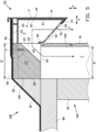
- Figures 1 and 4 show a building 8 with a roof 80, a cladded wall 9 and a roof trim set 1 for ventilating a cavity C of said cladded wall 9 according to a first exemplary embodiment of the invention.
- the roof 80 is a flat roof.
- the roof 80 may be provided with angle fillets 81, for example a triangular mastic piece, along the perimeter or the marginal portion of said roof 80.
- the roof 80 is waterproofed with a waterproofing layer 82, for example an asphalt or bitumen-based layer, which is shown only partially in figure 1 .
- the cladded wall 9 comprises an inner wall 90, for example a masonry wall or a wooden frame wall.
- the inner wall 90 extends vertically, substantially vertically or in a vertical direction Z.
- the cladded wall 9 is provided with siding or cladding 91.
- the cladded wall 9 further comprises posts, studs, laths or battens 92 for spacing apart the cladding 91 from the inner wall 90.
- the battens 92 extend vertically, substantially vertically or in the vertical direction Z.
- one or more of the battens may extend horizontally or in a different direction.
- the battens may be provided with openings to allow for a vertical draft of air through the cavity C.
- the battens 92 are spaced apart in a longitudinal direction Y perpendicular to said vertical direction Z.
- each pair of two battens 92 forms or defines the cavity C of the cladded wall 9.
- the thickness of the battens 92 in a lateral direction X perpendicular to the longitudinal direction Y and the vertical direction Z defines a width A of the cavity C, as shown in figure 4 .
- the cavity C extends vertically, substantially vertically or in the vertical direction Z between said battens 92.
- the cavity C is open at the top end of the cladded wall 9.
- the roof trim set 1 comprises a mounting member, a mounting bar or a mounting beam 2 that is mountable to or at the top end of said cladded wall 9 in a position covering a cavity C of said cladded wall 9.
- the mounting beam 2 has a mounting beam body 20 extending in the longitudinal direction Z parallel to the cladded wall 9 when mounted to said cladded wall 9.
- the mounting beam body 20 has a first lateral side 21 in the lateral direction X and a second lateral side 22, opposite to the first lateral side 21 in said lateral direction X.
- the mounting beam body 20 further has a width or a thickness B between the first lateral side 21 and the second lateral side 22 that is equal to or larger than the width A of the cavity C.
- the mounting body 20 further has a top side 23 facing upwards in the vertical direction Z and a bottom side 24, opposite to said top side 23, facing downwards in said vertical direction Z.
- the mounting beam 2 is configured to be mounted to the cladded wall 9 and/or the roof 9 in such a way that the first lateral side 21 faces outwards with respect to the cladded wall 9 and the bottom side 24 faces towards the cavity C.
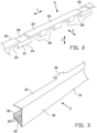
- the mounting beam 2 further comprises a plurality of ventilation cutouts, recesses or passageways 25 which are distributed and/or spaced apart along the length of the mounting beam body 20 in the longitudinal direction Y.
- the ventilation passageways 25 are formed as cutouts that interrupt the edge between the first lateral side 21 and the bottom side 24. More in particular, the passageways 25, in the cross section of figure 4 , define a triangular volume extending between the first lateral side 21 and the bottom side 24.
- the mounting beam body 20 has a rectangular or substantially rectangular cross section which can be used to fix, mount or attach the mounting beam 2 in stable and/or rigid manner to the battens 92 at the top end of the cladded wall 9.
- the mounting beam 2 is further provided with a plurality of direct mounting sections 26, the function of which will be discussed in more detail hereafter.
- the direct mounting sections 26 are recessed with respect to the top side 23 of the mounting beam body 20.
- the mounting beam 2 is made from wood.
- the mounting beam 2 may start out as a regular wooden beam having a constant, rectangular cross section.
- the ventilation passageways 25 and the direct mounting sections 26 are machined into said wooden beam.
- the mounting beam 2 may be made from a different material, such as plastic or metal, that is pre-formed with the ventilation passageways 25 and/or the direct mounting sections 26.
- the roof trim set 1 further comprises an edge profile or edge trim 3 that is mountable to or at the first lateral side 21 of the mounting beam 2.
- the edge trim 3 is located at least partially outside of the cladded wall 9 in the lateral direction X.
- the edge trim 3 comprises an edge trim body 30 having a first lateral side 31 and a second lateral side 32, opposite to the first lateral side 31, in the latera direction x.
- the edge trim body 30 further has a top side 33 and a bottom side 34, opposite to the top side 33, in the vertical direction Z.
- the edge trim 3 is configured to be mounted relative to the mounting beam 2 in such a way that the first lateral side 31 faces outwards and the bottom side 34 faces downwards.
- the bottom side 34 defines a ventilation surface having one or more ventilation openings or ventilation apertures 35.
- the ventilation apertures 35 together form a grating-like pattern.
- the bottom side 34 extends at an oblique angle K to the cladded wall 9 when the edge trim 3 is mounted, such that the bottom side 34 is at least partially hidden from an outside observer behind the first lateral side 31.
- the second lateral side 32 of the edge trim body 30 is formed as a flange or rim that can rest against first lateral side 21 of the mounting beam body 20 and/or the wall cladding 91 of the cladded wall 9.
- the first lateral side 31, the second lateral side 32, the top side 33 and the bottom side 34 of the edge trim 3 together form a cross sectional profile of the edge trim 3 that defines an internal volume H.
- the ventilation apertures 35 are arranged in fluid or air communication with said internal volume H to ventilate the internals of the edge trim 3.
- the mounting beam body 20 closes and/or seals the internal volume H at the first lateral side 21, except at the position of the ventilation passageways 25.
- the edge trim 3 further comprises at least one fastening section 36 protruding from the edge trim body 30 towards the mounting beam 2 when the edge trim 3 is positioned at the first lateral side 21 of the mounting beam 2.
- the at least one fastening section 36 can be aligned with and/or placed in an overlapping relationship with one of the direct mounting sections 26 of the mounting beam 2 for direct mounting of the edge trim 3 to said mounting beam 2. Because of the recessed position of said direct mounting sections 26, the edge trim 3 can be mounted in a flush or recessed manner with respect to the top side 23 of the mounting beam body 20.
- the unoccupied volume of the recesses formed by any one of said direct mounting sections 26 can be filled up with inserts, for example from wood, or a plastically deformable filling material, to obtain a flush or flat top side 23 of the mounting beam body 20.
- inserts for example from wood, or a plastically deformable filling material
- the edge trim 3 is made from metal, for example aluminum.
- the edge trim 3 can be made of another suitable material, such as plastic.
- the ventilation passageways 25 connect the ventilation apertures 35 in air communication (as schematically shown with air flow arrow F) with the cavity C via the first lateral side 21 and the bottom side 24, respectively, of the mounting beam body 20.
- the cavity C can be ventilated via the roof trim set 1.
- the roof trim set 1 further comprises a roof trim 4 that is mountable to the edge trim 3.
- the roof trim 4 has a roof trim body 40 with a first lateral side 41 facing outwards in the lateral direction X, a top side 42 facing upwards in the vertical direction Z and a bottom side 44, opposite to the top side 42, facing downwards in the vertical direction Z.
- the roof trim 4 is configured for snap-fit interlock with the edge trim 3.
- the roof trim body 40 is sufficiently flexible to snap-fit around the edge trim 3.
- the bottom side 44 of the roof trim body 40 is configured to hook around the lower edge of the edge trim 3.
- the roof trim 4 can be mounted without the use of tools.
- the roof trim 4 is provided with a roof termination surface 43 for terminating the waterproofing layer 82 of the roof 80.
- the roof termination surface 43 may be provided with a texture, ridges or corrugations to retain the waterproofing layer 82.
- the edge trim 3 may be provided with further ventilation apertures (not shown) in the top side 33 or the first lateral side 31 to allow moisture, for example as a result of condensation, to escape from any volume between the edge trim 3 and the roof trim 4.
- Figure 5 shows an alternative building 108 that differs from the aforementioned building 8 in that its cladded wall 109 is formed with wider or thicker battens 192. Consequently, the width A' of the cavity C in the lateral direction X is larger than the width A of the cavity C as shown in figure 4 .
- an alternative roof trim set 101 according to a second exemplary embodiment of the invention is used to ventilate said cavity C.
- the alternative roof trim set 101 differs from the aforementioned roof trim set 1 in that the mounting beam 102 has a mounting beam body 120 with a thickness or a width B' that is wider than the thickness or width B of the mounting beam body 20 as shown in figure 5 .
- the mounting bar 2, 102 may be chosen from a collection of mounting bars 2, 102 having different dimensions.
- the widths B, B' of the mounting beam bodies 20, 120, as shown in figures 4 and 5 may differ for the mounting bars 2, 102 in the collection.
- the mounting bars 2, 102 may have different heights, lengths and/or the ventilation passageways 26 formed therein may be different in size, shape and/or specification.
- the alternative mounting bar 102 of figure 5 may be adapted or modified, for example by machining, to the dimensions of the mounting bar 2 as shown in figure 4 , for example by cutting off excess thickness or width at the second lateral side 22, the top side 23 or any other side of the mounting bar body 120, as long as air communication functionality of the passageways 25 is maintained.
- FIG. 6 shows a further alternative roof trim set 201 according to a third exemplary embodiment of the invention, that differs from the aforementioned roof trim sets 1, 101 in that the functionality of the roof trim 4 and the edge 3 have been integrated into a single, integrated edge trim 203.
- the edge 203 has a first lateral side 231 facing outwards in the lateral direction X, a second lateral side 232, opposite to the first lateral side 231 in the lateral direction X, a top side 233 facing upwards in the vertical direction Z and a bottom side 234, opposite to the top side 233, facing downwards in the vertical direction Z.
- the first lateral side 231 now forms the outer surface of the further alternative roof trim set 201, instead of the separate roof trim 4.
- the top side 233 is provided with a roof termination surface for terminating the waterproofing layer 82 of the roof 80, like the top side 43 of the roof trim 4 in figure 4 .
- the edge trim 203 in figure 6 further differs from the edge trim 3 in figure 4 in that there is no fastening section for direct mounting of the edge trim 203 to the mounting member 202. Accordingly, the mounting body 220 of the mounting member 202 does not have a direct mounting section. Instead, the edge trim 203 is mounted at the first lateral side 21 of the mounting member 202 by sandwiching said edge trim 203 between the waterproofing layer 82 and the top side 23 of said mounting member 202. Note that this type of indirect mounting of the edge trim 203 to the mounting member 202 may also be applied, mutatis mutandis, to the roof trim sets 1, 101 of figures 1-5 .
- the shape, size, dimensions, materials and/or specifications of the mounting bar 2, 202, the edge trim 3, 203 and/or the roof trim 4 may be varied, not only for best matching the respective roof trim sets 1, 101, 201 to the respective buildings 8, 108, but also for esthetic purposes.
- other functionalities known in the field of roof trims may be applied to the roof trim sets 1, 101, 201 according to the present invention, for example features relating to forming joints at corners of a roof, or features relating to drip catching.
Landscapes
- Engineering & Computer Science (AREA)
- Architecture (AREA)
- Civil Engineering (AREA)
- Structural Engineering (AREA)
- Building Environments (AREA)
Applications Claiming Priority (1)
| Application Number | Priority Date | Filing Date | Title |
|---|---|---|---|
| NL2030177A NL2030177B1 (en) | 2021-12-17 | 2021-12-17 | Roof trim set, building comprising said roof trim set and method for ventilating a cladded wall |
Publications (3)
| Publication Number | Publication Date |
|---|---|
| EP4198219A1 true EP4198219A1 (de) | 2023-06-21 |
| EP4198219B1 EP4198219B1 (de) | 2026-03-18 |
| EP4198219C0 EP4198219C0 (de) | 2026-03-18 |
Family
ID=84360510
Family Applications (1)
| Application Number | Title | Priority Date | Filing Date |
|---|---|---|---|
| EP22208573.0A Active EP4198219B1 (de) | 2021-12-17 | 2022-11-21 | Gebäude mit einem dachziergarnitursatz und verfahren zur belüftung einer verkleideten wand |
Country Status (2)
| Country | Link |
|---|---|
| EP (1) | EP4198219B1 (de) |
| NL (1) | NL2030177B1 (de) |
Citations (7)
| Publication number | Priority date | Publication date | Assignee | Title |
|---|---|---|---|---|
| US2777381A (en) | 1954-09-10 | 1957-01-15 | Noyes | Roof ventilating devices |
| GB2142947A (en) * | 1983-06-27 | 1985-01-30 | John Longworth | Ventilated roof abutment curb |
| US20070193150A1 (en) * | 2005-09-09 | 2007-08-23 | Premier Forest Products, Inc. | Siding system and method |
| US8281522B1 (en) * | 2010-09-21 | 2012-10-09 | Andrei Hawryshko | Ventilated roofing system |
| ITMI20111317A1 (it) * | 2011-07-15 | 2013-01-16 | Uni Politecnica Delle Marche | Modulo per cappotto e cappotto |
| US20130227900A1 (en) * | 2012-03-01 | 2013-09-05 | Joseph Peterson | Insulating Member for Building Construction |
| JP2019090167A (ja) * | 2017-11-10 | 2019-06-13 | ケイミュー株式会社 | 通気構造及び断熱材付き通気部材 |
-
2021
- 2021-12-17 NL NL2030177A patent/NL2030177B1/en active
-
2022
- 2022-11-21 EP EP22208573.0A patent/EP4198219B1/de active Active
Patent Citations (7)
| Publication number | Priority date | Publication date | Assignee | Title |
|---|---|---|---|---|
| US2777381A (en) | 1954-09-10 | 1957-01-15 | Noyes | Roof ventilating devices |
| GB2142947A (en) * | 1983-06-27 | 1985-01-30 | John Longworth | Ventilated roof abutment curb |
| US20070193150A1 (en) * | 2005-09-09 | 2007-08-23 | Premier Forest Products, Inc. | Siding system and method |
| US8281522B1 (en) * | 2010-09-21 | 2012-10-09 | Andrei Hawryshko | Ventilated roofing system |
| ITMI20111317A1 (it) * | 2011-07-15 | 2013-01-16 | Uni Politecnica Delle Marche | Modulo per cappotto e cappotto |
| US20130227900A1 (en) * | 2012-03-01 | 2013-09-05 | Joseph Peterson | Insulating Member for Building Construction |
| JP2019090167A (ja) * | 2017-11-10 | 2019-06-13 | ケイミュー株式会社 | 通気構造及び断熱材付き通気部材 |
Also Published As
| Publication number | Publication date |
|---|---|
| EP4198219B1 (de) | 2026-03-18 |
| NL2030177B1 (en) | 2023-06-28 |
| EP4198219C0 (de) | 2026-03-18 |
Similar Documents
| Publication | Publication Date | Title |
|---|---|---|
| US8205398B2 (en) | Fascia vent | |
| US5832677A (en) | Eve air vent | |
| CA2523692C (en) | Vented soffit panel | |
| EP0539909A1 (de) | Traufenlüftung und -abschlussprofil | |
| US4807409A (en) | Vented fascia board | |
| US20180258633A1 (en) | Insulation and ventilation systems for building structures | |
| US6997800B1 (en) | Roof vent system | |
| US8528270B2 (en) | Fascia vent | |
| US8528269B2 (en) | Fascia vent | |
| US5560157A (en) | Fascia vent | |
| US6620040B2 (en) | Moisture venting structure for the construction of walls | |
| EP4198219A1 (de) | Dachziergarnitursatz, gebäude mit diesem dachziergarnitursatz und verfahren zur belüftung einer verkleideten wand | |
| GB2127060A (en) | Improvements in roof ventilation | |
| US6718699B1 (en) | Placing inadvertently omitted ventilation strip | |
| US5729935A (en) | Gable vent | |
| US3373676A (en) | Eave venting system utilizing a ventilated fascia member | |
| US20070256372A1 (en) | Component gable vent | |
| US7743571B2 (en) | Injection moldable composite gable vent | |
| US20040200170A1 (en) | Board fastener with underside ventilation | |
| JPH0421370Y2 (de) | ||
| CA2458006A1 (en) | Soffit structure | |
| JPH0529284Y2 (de) | ||
| CA3057231C (en) | Perforated eave trim and roof ventilation system | |
| CA2199392C (en) | Fascia vent | |
| JPS625457Y2 (de) |
Legal Events
| Date | Code | Title | Description |
|---|---|---|---|
| PUAI | Public reference made under article 153(3) epc to a published international application that has entered the european phase |
Free format text: ORIGINAL CODE: 0009012 |
|
| STAA | Information on the status of an ep patent application or granted ep patent |
Free format text: STATUS: THE APPLICATION HAS BEEN PUBLISHED |
|
| AK | Designated contracting states |
Kind code of ref document: A1 Designated state(s): AL AT BE BG CH CY CZ DE DK EE ES FI FR GB GR HR HU IE IS IT LI LT LU LV MC ME MK MT NL NO PL PT RO RS SE SI SK SM TR |
|
| STAA | Information on the status of an ep patent application or granted ep patent |
Free format text: STATUS: REQUEST FOR EXAMINATION WAS MADE |
|
| 17P | Request for examination filed |
Effective date: 20231214 |
|
| RBV | Designated contracting states (corrected) |
Designated state(s): AL AT BE BG CH CY CZ DE DK EE ES FI FR GB GR HR HU IE IS IT LI LT LU LV MC ME MK MT NL NO PL PT RO RS SE SI SK SM TR |
|
| STAA | Information on the status of an ep patent application or granted ep patent |
Free format text: STATUS: EXAMINATION IS IN PROGRESS |
|
| 17Q | First examination report despatched |
Effective date: 20240531 |
|
| GRAP | Despatch of communication of intention to grant a patent |
Free format text: ORIGINAL CODE: EPIDOSNIGR1 |
|
| STAA | Information on the status of an ep patent application or granted ep patent |
Free format text: STATUS: GRANT OF PATENT IS INTENDED |
|
| INTG | Intention to grant announced |
Effective date: 20250228 |
|
| GRAJ | Information related to disapproval of communication of intention to grant by the applicant or resumption of examination proceedings by the epo deleted |
Free format text: ORIGINAL CODE: EPIDOSDIGR1 |
|
| STAA | Information on the status of an ep patent application or granted ep patent |
Free format text: STATUS: EXAMINATION IS IN PROGRESS |
|
| GRAP | Despatch of communication of intention to grant a patent |
Free format text: ORIGINAL CODE: EPIDOSNIGR1 |
|
| STAA | Information on the status of an ep patent application or granted ep patent |
Free format text: STATUS: GRANT OF PATENT IS INTENDED |
|
| INTC | Intention to grant announced (deleted) | ||
| INTG | Intention to grant announced |
Effective date: 20250724 |
|
| GRAS | Grant fee paid |
Free format text: ORIGINAL CODE: EPIDOSNIGR3 |
|
| GRAA | (expected) grant |
Free format text: ORIGINAL CODE: 0009210 |
|
| STAA | Information on the status of an ep patent application or granted ep patent |
Free format text: STATUS: THE PATENT HAS BEEN GRANTED |
|
| AK | Designated contracting states |
Kind code of ref document: B1 Designated state(s): AL AT BE BG CH CY CZ DE DK EE ES FI FR GB GR HR HU IE IS IT LI LT LU LV MC ME MK MT NL NO PL PT RO RS SE SI SK SM TR |
|
| REG | Reference to a national code |
Ref country code: CH Ref legal event code: F10 Free format text: ST27 STATUS EVENT CODE: U-0-0-F10-F00 (AS PROVIDED BY THE NATIONAL OFFICE) Effective date: 20260318 Ref country code: GB Ref legal event code: FG4D |
|
| REG | Reference to a national code |
Ref country code: DE Ref legal event code: R096 Ref document number: 602022032493 Country of ref document: DE |
|
| REG | Reference to a national code |
Ref country code: IE Ref legal event code: FG4D |
|
| U01 | Request for unitary effect filed |
Effective date: 20260324 |
|
| U07 | Unitary effect registered |
Designated state(s): AT BE BG DE DK EE FI FR IT LT LU LV MT NL PT RO SE SI Effective date: 20260330 |