EP4198220A1 - Escalier et procédé de montage d'un tel escalier, et procédé de fabrication d'une pièce d'escalier - Google Patents
Escalier et procédé de montage d'un tel escalier, et procédé de fabrication d'une pièce d'escalier Download PDFInfo
- Publication number
- EP4198220A1 EP4198220A1 EP21215660.8A EP21215660A EP4198220A1 EP 4198220 A1 EP4198220 A1 EP 4198220A1 EP 21215660 A EP21215660 A EP 21215660A EP 4198220 A1 EP4198220 A1 EP 4198220A1
- Authority
- EP
- European Patent Office
- Prior art keywords
- staircase
- railing
- tread
- riser
- edge
- Prior art date
- Legal status (The legal status is an assumption and is not a legal conclusion. Google has not performed a legal analysis and makes no representation as to the accuracy of the status listed.)
- Granted
Links
Images


Classifications
-
- E—FIXED CONSTRUCTIONS
- E04—BUILDING
- E04F—FINISHING WORK ON BUILDINGS, e.g. STAIRS, FLOORS
- E04F11/00—Stairways, ramps, or like structures; Balustrades; Handrails
- E04F11/02—Stairways; Layouts thereof
- E04F11/104—Treads
- E04F11/112—Treads of metal or with an upper layer of metal
-
- B—PERFORMING OPERATIONS; TRANSPORTING
- B21—MECHANICAL METAL-WORKING WITHOUT ESSENTIALLY REMOVING MATERIAL; PUNCHING METAL
- B21D—WORKING OR PROCESSING OF SHEET METAL OR METAL TUBES, RODS OR PROFILES WITHOUT ESSENTIALLY REMOVING MATERIAL; PUNCHING METAL
- B21D11/00—Bending not restricted to forms of material mentioned in only one of groups B21D5/00, B21D7/00, B21D9/00; Bending not provided for in groups B21D5/00 - B21D9/00; Twisting
- B21D11/10—Bending specially adapted to produce specific articles, e.g. leaf springs
-
- B—PERFORMING OPERATIONS; TRANSPORTING
- B21—MECHANICAL METAL-WORKING WITHOUT ESSENTIALLY REMOVING MATERIAL; PUNCHING METAL
- B21D—WORKING OR PROCESSING OF SHEET METAL OR METAL TUBES, RODS OR PROFILES WITHOUT ESSENTIALLY REMOVING MATERIAL; PUNCHING METAL
- B21D11/00—Bending not restricted to forms of material mentioned in only one of groups B21D5/00, B21D7/00, B21D9/00; Bending not provided for in groups B21D5/00 - B21D9/00; Twisting
- B21D11/20—Bending sheet metal, not otherwise provided for
-
- B—PERFORMING OPERATIONS; TRANSPORTING
- B21—MECHANICAL METAL-WORKING WITHOUT ESSENTIALLY REMOVING MATERIAL; PUNCHING METAL
- B21D—WORKING OR PROCESSING OF SHEET METAL OR METAL TUBES, RODS OR PROFILES WITHOUT ESSENTIALLY REMOVING MATERIAL; PUNCHING METAL
- B21D53/00—Making other particular articles
-
- E—FIXED CONSTRUCTIONS
- E04—BUILDING
- E04F—FINISHING WORK ON BUILDINGS, e.g. STAIRS, FLOORS
- E04F11/00—Stairways, ramps, or like structures; Balustrades; Handrails
- E04F11/02—Stairways; Layouts thereof
- E04F2011/0203—Miscellaneous features of stairways not otherwise provided for
- E04F2011/0205—Stairways characterised by the use of specific materials for the supporting structure of the treads
- E04F2011/0209—Stairways characterised by the use of specific materials for the supporting structure of the treads mainly of metal
-
- E—FIXED CONSTRUCTIONS
- E04—BUILDING
- E04F—FINISHING WORK ON BUILDINGS, e.g. STAIRS, FLOORS
- E04F11/00—Stairways, ramps, or like structures; Balustrades; Handrails
- E04F11/18—Balustrades; Handrails
- E04F2011/1885—Handrails or balusters characterized by the use of specific materials
- E04F2011/1889—Handrails or balusters characterized by the use of specific materials mainly of metal
Definitions
- the invention considers a staircase and a method for mounting such staircase. Further, a production method for producing a staircase part is disclosed.
- Staircases consist of four main components, railings (or baluster), handrail, stair treads and landings. Other parts of a staircase are for example risers, stringers, followers, bolts etc. Risers may cover parts or the whole distance between the treads and the so-called followers are an alternative form of a stringer and may for example be one or two flat steel followers which runs between the steps, and by that connects the steps at its outer edges, wherein the construction becomes stable.
- a spiral staircase normally comprises a pillar to which the treads are screwed, wherein the staircase runs around the central pillar upwards and a stringer, or one or more flat steel followers, connects the outer ends of the treads to make the staircase stable.
- railings (balusters) are mounted to the outer ends of the treads and handrails are mounted to the railings or to the treads via railing posts and sometimes, an inner handrail is mounted to the central pillar.
- the treads of the staircase may be made in various designs, materials and so on, and may comprise perforations with a hole pattern and design of the holes to cope with issues like providing a non-slippery surface.
- staircase One type of known staircase is where the treads are made of steel grating, where load bearing bars are joined with cross bars under high pressure and high amperage which gives a welded joint at each connection between load bearing and cross bars. Edging bars are welded perpendicularly to the bearing bars on the grating and the gratings are then normally hot dip galvanized, before they are ready to be packed and sent to a site for mounting to a complete staircase.
- a common type of spiral staircase comprises a metal pillar, to which the stair treads are fixedly attached by screws which connects the treads directly to the pillar or to brackets which in turn are fixedly connected to the central pillar. Further, this type comprises flat steel “followers", which are metal bands which are screwed to the outer ends of the treads, one upper and one lower. Of course, one wide steel follower may be used. To the outer ends of the treads or to the followers, some kind of railings are mounted.
- the railings may, depending on visual and/or safety issues be in form vertical bars, horizontal bars, combinations of horizontal and vertical bars, perforated or unperforated sheet metal, wire mesh, glass etc. Due to safety reasons, the railings must have a certain height, which height normally is higher than the natural height for a handrail, why the handrail must be positioned a bit below the upper edge of the railing.
- Known metal staircases are produced like single parts, where some of the parts are welded to each other and after the details are in a "ready" state, the parts are then normally galvanized to protect the steel from corrosion, as explained for a known staircase above.
- the kit When delivering a complete staircase, the kit comprises a lot of components which are to be mounted to each other to build up the staircase.
- the kit for a complete staircase in known art is bulky and to mount a complete staircase is time-consuming with a lot of components to handle and mount.
- one other problem with known staircases is that some parts first must be welded and then galvanized, why the lack possibility to produce the parts directly from a galvanized raw material, for example from a coil of galvanized steel.
- a complete staircase comprises a plurality of staircase parts which are mounted consecutively to each other, and wherein each staircase part consists of one single sheet metal part.
- Each staircase part comprises a tread part, a riser part and at least one railing part, which all preferably are substantially flat, and wherein the tread part comprises a back edge, a front edge, which is opposite the back edge, and further a first side edge and a second side edge, which is opposite the first side edge.
- the back edge, the front edge and the first and second side edge thereby encloses the tread part.
- the riser part is arranged along the back edge of the tread part and extends in a first direction, which preferably is perpendicular to the tread part, but the inventive concept also discloses other angles of the riser part relative the tread part.
- the design of the riser part may comprise different bends and angles to provide a certain design, as long as the riser part origins from the one single sheet metal part. By that, a free riser edge of the riser faces away from the tread part.
- the railing part is arranged along the first side edge of the tread part and extends in the first direction, which preferably is perpendicular to the tread part such as a free railing edge faces away from the tread part.
- the inventive concept also discloses other angles of the railing part relative the tread part.
- the design of the railing part may comprise different bends and angles to provide a certain design, as long as the railing part origins from the one single sheet metal part.
- Such a staircase is unique in that a lot of parts which normally are parts of a staircase, particularly for a metal staircase, are integrated in the modular staircase parts, which further by their design contribute to the overall stability and strength of the staircase, thus resulting in a reduced number of parts.
- the staircase parts are fixedly connected to each other in many positions along the parts.
- the reduced number of parts are positive in view of environment (less details, less weight, transport etc.) as well in view of mounting time.
- a prior art spiral metal staircase comprises a number of individual parts as a plurality of steps, risers, railing parts, outer metal rim bands/followers which connects the plurality of steps to each other, handrail etc.
- the inventive staircase which achieves a good strength and stability and a quick and easy mounting.
- One further positive aspect is that the thickness of the steel sheet metal may be reduced compared to similar staircases of known art.
- the free edge of the riser part of a lower arranged staircase part of the plurality of staircase parts is connected to the tread part of an upper arranged staircase part of the plurality of staircase parts positioned immediately adjacent the lower staircase part, preferably to its front edge.
- the free riser edge may be connected to the tread part in any "depth location" between the front edge and the back edge of the tread part of the upper staircase part so the invention is not limited to a connection with the front edge.
- the tread part of each staircase part further comprises a nose part, arranged along the front edge of the tread part, wherein the nose part of an upper arranged staircase part of the plurality of staircase parts is connected to the free riser edge of the riser part of a lower arranged staircase part of the plurality of staircase parts, positioned immediately adjacent the upper staircase part, or to a riser part which is not part of any other of the plurality of staircase parts, if the upper arranged staircase part is a lowermost staircase part.
- the tread part gets increased stability as well as the nose part provides a natural connection point for the free riser edge of a lower staircase part.
- the nose part of each staircase part comprises a plurality of first through holes and the riser part of each staircase part comprises a corresponding number of second through holes arranged near the free riser edge of the riser part.
- the free riser edge of a lower staircase part is easily connected to the nose part of an upper staircase part.
- the first through holes of the nose part do not have threads and the second through holes of the riser part comprise threads.
- the railing part of each staircase part of the plurality of staircase parts comprises at least one first tongue part, arranged along a back edge of each railing part, which first tongue part of a lower arranged staircase part of the plurality of staircase parts is connected to a front edge of a railing part of an upper staircase part or to a post.
- first tongue part of a lower arranged staircase part of the plurality of staircase parts is connected to a front edge of a railing part of an upper staircase part or to a post.
- the tongue part of each staircase part comprises a plurality of third through holes and the railing part of each staircase part further comprises a corresponding number of fourth through holes arranged near the front edge of the railing part.
- the third through holes of the tongue part have threads and the fourth through holes at the front edge do not comprise threads.
- the riser part of each staircase part comprises at least one second tongue part arranged along a second side edge of the riser part, which second side edge faces away from the railing part, wherein the at least one second tongue part comprises at least one fifth through hole.
- the staircase part may be screwed to a wall or a center pillar or the like, in a very convenient way, since the second tongue part may easily be adopted to the surface, or the angle between the surface (of the wall or pillar) by bending it further on site, if the predetermined angle is a bit wrong.
- the fifth through hole do not have threads but underlying fixation means/holes of the pillar may comprise threads, for fixation of the staircase part to the pillar.
- the wall may comprise fixation means or not, depending on the wall material (steel, concrete, wood, etc.).
- the staircase is a spiral staircase, wherein the thread part of each staircase part has a substantially triangular shape, wherein the staircase further comprises a center pillar extending in the first direction, which preferably is a vertical direction, wherein each staircase part further is fixedly attached to the center pillar.
- This may be done via the second tongue part of the riser, if the riser is equipped with that tongue part, or via another part of the stair tread, for example a tongue or the like arranged directly on the second edge of the tread part.
- the pillar comprises a plurality of fixation means, for example holes, arranged spaced apart in the first direction and circumferentially around the pillar in a spiral pattern, wherein each riser part of the plurality of staircase parts may be fixedly attached to the center pillar.
- fixation means for example holes, arranged spaced apart in the first direction and circumferentially around the pillar in a spiral pattern, wherein each riser part of the plurality of staircase parts may be fixedly attached to the center pillar.
- the staircase further comprising a floor part (landing), which at least is attached to the riser part of the uppermost staircase part of the staircase, and preferably also to a building part and/or a pillar, if applicable.
- a floor part which at least is attached to the riser part of the uppermost staircase part of the staircase, and preferably also to a building part and/or a pillar, if applicable.
- a kit of parts for a staircase comprises a plurality of staircase parts, wherein each staircase part consists of one single sheet metal part.
- Each staircase part comprises a tread part, a riser part and at least one railing part, wherein the tread part comprises a back edge, a front edge, which is opposite the back edge, and further a first side edge and a second side edge, which is opposite the first side edge.
- the riser part is arranged along the back edge of the tread part and extends in a first direction, which preferably is perpendicular to the tread part, but the inventive concept also discloses other angles of the riser part relative the tread part.
- the design of the riser part may comprise different bends and angles to provide a certain design, as long as the riser part origins from the one single sheet metal part.
- a free riser edge of the riser faces away from the tread part.
- the railing part is arranged along the first side edge of the tread part and extends in the first direction, which preferably is perpendicular to the tread part such as a free railing edge faces away from the tread part.
- the inventive concept also discloses other angles of the railing part relative the tread part.
- the design of the railing part may comprise different bends and angles to provide a certain design, as long as the railing part origins from the one single sheet metal part.
- Such kit of parts may easily be loaded on a one single pallet which then may comprise only one type of parts, which is far better and more convenient compared to prior art staircases.
- the kit of parts may of course further comprise, attachment means, pillar, handrail etc.
- a method for mounting a staircase as described above is disclosed.
- the staircase is mounted between a lower floor level and an upper floor level in a building or the like, starting from a lowermost stair tread of the staircase.
- the method comprising:
- the staircase comprises a plurality of staircase parts which are mounted consecutively to each other, wherein each staircase part consists of one single sheet metal part.
- Each staircase part comprises a tread part, a riser part and at least one railing part, which all preferably are substantially flat, and wherein the tread part comprises a back edge, a front edge, which is opposite the back edge, and further a first side edge and a second side edge, which is opposite the first side edge.
- the back edge, the front edge and the first and second side edge thereby encloses the tread part.
- the riser part is arranged along the back edge of the tread part and extends in a first direction, which preferably is perpendicular to the tread part, but the inventive concept also discloses other angles of the riser part relative the tread part.
- a free riser edge of the riser faces away from the tread part.
- the railing part is arranged along the first side edge of the tread part and extends in the first direction, which preferably is perpendicular to the tread part such as a free railing edge faces away from the tread part.
- a method for mounting a staircase wherein the staircase is a spiral staircase and wherein the spiral staircase comprises a center pillar, to which the staircase parts are to be mounted, the method further comprising, before the above presented step a):
- the spiral staircase comprises as mentioned some kind of pillar or central wall or the like, around which the staircase runs upwards in a spiral way, and in the case of having a pillar, the method steps i) - iii) are applicable.
- the bottom plate may be used to easier secure the lower end of the pillar to the floor, and when the pillar is positioned and secured, the mounting according to step a) - step j) may start.
- a method for mounting an alternative staircase between a lower floor level and an upper floor level in a building or the like starts in a similar way by mounting a lowermost stair tread of the staircase.
- the alternative staircase is more or less similar with the previously described staircase but now each staircase part comprises two railing parts.
- One railing part is arranged along the first side edge of the tread part (similar with the former described staircase) and extends in the first direction such as a free railing edge faces away from the tread part, and one other railing part is arranged along the second side edge of the tread part and extends in the first direction such as a free railing edge faces away from the tread part.
- the method comprising:
- a straight or angled staircase with one railing part at respective sides of the staircase may be mounted according to the inventive concept.
- a method for producing a staircase part from a roll of sheet metal comprising:
- the method further comprising:
- a staircase part which comprises tread part, riser part and railing part from a roll of sheet metal a number of advantages are achieved.
- the roll of sheet metal may already by galvanized, which is a great advantage over prior art staircases, which normally first must be produced as single parts which are not galvanized since a number of welding operations must be performed before galvanization is possible.
- the inventive production method eliminates a number of steps and speed up the production process of a complete staircase.
- Other advantages are for example elimination transports and intermediate storage of the different parts since it is now possible to produce the staircase parts from the roll to a final product which is ready for delivery.
- a staircase which is constructed by a plurality of modular staircase parts is disclosed. Further, methods for mounting different kinds of staircases, like a spiral staircase, a straight or angled staircase and the like, which are constructed by such modular staircase parts are disclosed as well as a method for producing such staircase part.
- the inventive staircase and methods for producing and mounting a staircase comprising the inventive staircase parts enables a very cost-efficient staircase due to very few parts and which further enables a very space-efficient and easy handled transport of the complete staircase. Further, a very quick mounting of the staircase on sight minimizes mounting time and thereby mounting costs.
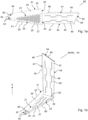
- Fig. 1a-b show a top view of a flat single sheet metal part 60 ( Fig. 1a ) and the single sheet metal part 60 when it is bent to form a staircase part 6a, 6b, ..., 6n ( Fig. 1b ).
- a plurality of staircase parts 6a, 6b, ..., 6n are used to together form a complete staircase (see Fig. 2 ), which according to the inventive concept reduces the number of parts and thus speeds up the mounting of the staircase.
- Each staircase part 6a, 6b, ..., 6n as visible in Fig. 1b as well as the sheet metal part 60 as visible in Fig. 1a comprises a tread part 20, a riser part 30 and one railing part 40.
- 1a-b show the sheet metal part 60/ the staircase part 6a, 6b, ..., 6n when designed for a spiral staircase, where the tread part 20 has a substantially triangular shape, and where the staircase parts 6a, 6b, ..., 6n normally are attached to a center pillar or a center wall or a similar building part or the like.
- the sheet metal part 60/ the staircase part 6a, 6b, ..., 6n would have a rectangular tread part 20 and preferably would comprise a second railing part 40, opposite the right railing part 40 of Figs. 1a-b .
- the tread part 20 comprises a back edge 21, a front edge 23 which is opposite the back edge 21, and further a first side edge 22 and a second side edge 24 opposite the first side edge 22.
- each tread part 20 may comprise a non-slippery surface or some kind of anti-slip arrangement 27, which may be in the form of a perforation made in such a way that a plurality of holes is punched from the underside of the tread part 20, in a way to create an upwardly directed collars around the holes. The number of holes, the height of the collars as well as the design of the holes and the collars is proven to get the wanted anti-slip function.
- the tread part 20 further comprises a nose part 50, which is arranged as a bent tongue part along the front edge 23 of the tread part 20 of the staircase part 6a, 6b, ..., 6n.
- the nose part 50 is arranged to be connected to a free riser edge 31 of the riser part 30 of a lower arranged staircase part 6a, 6b, ..., 6n or to a riser part 70 which is not part of another staircase part 6a, 6b, ..., 6n, that is normally a riser part 70 arranged for the first (lowermost) step.
- the nose part 50 comprises a plurality of first through holes 51 and the riser part 30 comprises a corresponding number of second through holes 33, arranged near the free riser edge 31 of the riser part 30.
- the riser part 30 is explained further below.
- the railing part 40 is arranged along the first side edge 22 of the tread part 20 and protrudes in the first direction Z (upwards when mounted to a staircase) such as a free railing edge 44 faces away from the tread part 20.
- the railing part 40 further comprises a back edge 41, a front edge 43 opposite the back edge 41, and at least one first tongue part 45, which is arranged along the back edge 41 of the railing part 40 and extends in a direction perpendicular to the first direction Z, for example extending backwards with an angle relative the railing part 40.
- the first tongue part 45 is arranged to be connected to the front edge 43 of a railing part 40 of an adjacent staircase part 6a, 6b, ..., 6n or to a post 80 by that it comprises a plurality of third through holes 46.
- the railing part 40 further comprises a corresponding number of fourth through holes 47 arranged near the front edge 43 of the railing part 40, which are arranged in positions which correspond to the third through holes 46, when adjacent staircase part 6a, 6b, ..., 6n are mounted together to form the staircase 1, which of course depends on the height of the steps 2 (see Fig. 2 ) and the height of the riser 3/riser part 30.
- the railing part 40 may comprise a designed pattern of holes 48 or the like to create a visual effect and the pattern of holes 48 may vary within the concept from no holes to a very open structure/design of the railing part 40.
- the free railing edge 44 preferably comprise a tongue part 49, which in the formed (bent) staircase part 6a, 6b, ..., 6n, is bent to form a stable upper edge of the railing part 40.
- the riser part 30 is arranged along the back edge 21 of the tread part 20 and protrudes in the first direction Z, which is upwards in the vertical direction (when mounted), such as the free riser edge 31 faces away from the tread part 20. Further, the riser part 30 comprises a first side edge 32 and an opposite second side edge 34, wherein the first side edge 32 is arranged near the railing part 40. As mentioned above, the plurality of second through holes 33 is arranged near the free riser edge 31 of the riser part 30.
- the riser part 30 comprises at least one second tongue part 35, which is arranged along the second side edge 34 of the riser part 30, and the second tongue part 35 comprises at least one, but preferably two fifth through holes 36, wherein the second tongue part 35 is arranged to be connected to a center pillar or the like (see Fig. 2 ).
- Fig. 2 shows a perspective view of a staircase 1 according to the invention, which comprises a number of main parts in the form of a pillar 100, a floor part 110 (landing) and a plurality of staircase parts 6a, 6b, ..., 6n and which is mounted according to the inventive method.
- Fig. 3a shows a detailed side view of a part of the pillar 100 and shows how staircase parts 6a, 6b, ..., 6n are attached to the pillar 100 and
- Fig. 3b shows a section view through the pillar 100 of Fig. 3a .
- the staircase 1 is made of metal and comprises of course a plurality of stair treads 2 and risers 3 as well as a railing 4 and attachment means 5, the latter for fixedly attaching the parts to each other.
- the attachment means 5 may be screws, screw plus bolt and other types of known attachment means.
- the inventive staircase 1 is unique in that a lot of parts which normally are parts of a staircase, particularly a metal staircase, are integrated in the modular staircase parts 6a, 6b, ..., 6n which further by their design contribute to the overall stability and strength of the staircase, thus resulting in a reduced number of parts.
- the reduced number of parts are positive in view of environment (less details, less weight, transport etc.) as well in view of mounting time.
- a prior art spiral metal staircase comprises a number of individual parts as a plurality of steps, risers, railing parts, outer metal rim bands/followers which connects the plurality of steps to each other, handrail etc.
- all these parts except the handrail are integrated (or omitted) in the inventive staircase 1, which achieves a good strength and stability and a quick and easy mounting.
- Each staircase part 6a, 6b, ..., 6n is arranged to be connected to at least one other staircase part 6a, 6b, ..., 6n and also to be connected to the center pillar 100 and a post 80 or the like (where applicable), see Figs. 2 and 4 .
- only the first staircase part 6a and the last, uppermost staircase part 6n are connected, preferably by screws 5, to a respective post 80.
- the staircase 1 is mounted between a lower floor level and an upper floor level in a building or the like, from the bottom to the top such as the first stair tread 2 to be mounted, is the lowermost stair tread 2 of the staircase 1, i.e. the lowermost staircase part 6a.
- the first step 2 the riser 3 and the ceiling 4 (part of ceiling 4) is constituted by the first staircase part 6a.
- a first method step may be to first fixedly attach a bottom plate 103 to the floor of the lower floor level and then apply the pillar 100 to the bottom plate 103.
- a bottom plate 103 is as said optionally depending on the pillar design, but according to the preferred embodiment, a bottom plate 103 is used. After fixation of the bottom plate 103 to the floor, one positions a bottom end 101 of the center pillar 100 on the bottom plate 103 and then fixedly attaches the pillar 100 to the bottom plate 103 (or optionally direct to the floor if a bottom plate is not used).
- a second end 102 of the pillar 100 which is opposite the first end 101, may be attached to a ceiling or be a free end, like the staircase 1 of Fig. 2 .
- the pillar 100 has according to the preferred embodiment a circular cross-section, but may as well have a square, hexagonal, octagonal or other cross-section.
- the next method step is to attach a floor part 110 to a preferably uppermost fixation means of the center pillar 100, at a level close to or at the upper floor level and preferably also attach it to a building part of the building, for example a wall or an upper floor of the upper floor level, by some kind of fixation means. This is optionally, since the floor part 110 (or the landing which it is also called) may be omitted if the staircase 1 is possible to attach directly to the floor of the next floor level.
- the next step is to mount a first stair tread 2 by arranging one first staircase part 6a such as the railing part 40 faces away from the pillar 100 wherein it is possible to, after that, attaching/mounting the first staircase part 6a to a first fixation means 105a of the center pillar 100 by one or more attachment means 5, for example screws, wherein the second side edge 24 of the tread part 20 of the staircase part 6a is close to the pillar 100 and the first side edge 22 faces away from the pillar 100.
- the riser part 30 of each staircase part 6a, 6b, ..., 6n comprises the second tongue part 35, arranged along the second side edge 34 of the riser part 30, and the second tongue part 35 comprises two fifth through holes 36, wherein the second tongue part 35 is connected/screwed to the center pillar 100, see Figs. 3a-b .
- the fixation means 105a, 105b, ... 105n of the pillar preferably are holes in which a respective screw (attachment means 5) may be screwed to fixedly attach the second tongue part 35 of the riser 30 of each staircase part 6a, 6b, ...6n.
- the fixation means 105a, 105b, ..., 105n follows helically around and upwards along the circular pillar 100, like a spiral pattern.
- a riser 70 which not is a part of another staircase part 6a, 6b, ..., 6n may be mounted to the first staircase part 6a, by connecting the riser 70 to the tread part 20 of the first staircase part 6a, preferably to the nose part 50 of the same.
- the next step is to mount a next stair tread 2 by mounting one second staircase part 6b to the next second fixation means 105b of the center pillar 100 by one or more attachment means 5, in the same way as described above in relation to the first step 2.
- next stair tread 2 is fixedly attached to the pillar 100
- the following step is to mount another stair tread 2 by mounting one next staircase part 6c to the corresponding fixation means 105c of the center pillar 100 by one or more attachment means 5, in the same way as described above.
- the staircase 1 is the further mounted by repeating the above steps, for each step, until the uppermost stair tread 2 is attached to a fixation means 105n of the pillar 100 and to the stair tread 2 below the uppermost stair tread 2. Then, the riser part 30 of the uppermost stair tread 2 is attached to an upper floor of the upper floor level or to the floor part 110 by a plurality of attachment means 5.
- the staircase preferably comprises two posts 80, wherein the method for mounting the staircase 1 further comprises to attach one post 80 to the front edge 43 of the staircase part 6a of the first stair tread 2, and further to attach one second post 80 to the back edge 41 or the first tongue 45 of the uppermost staircase part 6n of the last stair tread 2 of the staircase 1, by a plurality of attachment means 5. This may be done at any time during the mounting, but preferably in connection to the mounting of respective first and last step 2.
- Fig. 4 shows a side view of a staircase 1 mounted according to the inventive method and comprising a number of staircase parts 6a, 6b, ..., 6n.
- the staircase 1 made of metal comprises in this case four stair treads 2 and the floor part 110.
- There are five risers 3 wherein four are riser parts 30 of respective staircase part 6a, 6b, 6c, 6d, and the first one is the "extra" riser 70.
- the railing 4 actually consists of four railing parts 40 attach to each other by attachment means 5, to form the complete railing 4.
- the first and the last riser part 40 are attached to a respective squared post 80.
- the railing part 40 comprises the designed pattern of holes 48 and the free railing edge 44 comprises the tongue part 49, which in the formed (bent) staircase part 6a, 6b, ..., 6n, is bent to form a stable upper edge of the railing part 40.
- Fig. 5 shows a section view of a part of a railing 4 of the staircase 1 of Fig. 4 which shows how a handrail 120 is screwed to the railing by a threaded spacer.
Landscapes
- Engineering & Computer Science (AREA)
- Mechanical Engineering (AREA)
- Architecture (AREA)
- Civil Engineering (AREA)
- Structural Engineering (AREA)
- Steps, Ramps, And Handrails (AREA)
Priority Applications (1)
| Application Number | Priority Date | Filing Date | Title |
|---|---|---|---|
| EP21215660.8A EP4198220B1 (fr) | 2021-12-17 | 2021-12-17 | Escalier et procédé de montage d'un tel escalier, et procédé de fabrication d'une pièce d'escalier |
Applications Claiming Priority (1)
| Application Number | Priority Date | Filing Date | Title |
|---|---|---|---|
| EP21215660.8A EP4198220B1 (fr) | 2021-12-17 | 2021-12-17 | Escalier et procédé de montage d'un tel escalier, et procédé de fabrication d'une pièce d'escalier |
Publications (3)
| Publication Number | Publication Date |
|---|---|
| EP4198220A1 true EP4198220A1 (fr) | 2023-06-21 |
| EP4198220C0 EP4198220C0 (fr) | 2025-11-19 |
| EP4198220B1 EP4198220B1 (fr) | 2025-11-19 |
Family
ID=78957307
Family Applications (1)
| Application Number | Title | Priority Date | Filing Date |
|---|---|---|---|
| EP21215660.8A Active EP4198220B1 (fr) | 2021-12-17 | 2021-12-17 | Escalier et procédé de montage d'un tel escalier, et procédé de fabrication d'une pièce d'escalier |
Country Status (1)
| Country | Link |
|---|---|
| EP (1) | EP4198220B1 (fr) |
Citations (2)
| Publication number | Priority date | Publication date | Assignee | Title |
|---|---|---|---|---|
| US5799448A (en) * | 1996-09-13 | 1998-09-01 | Harsco Corporation | Adjustable closed-riser metal staircase system |
| WO2010099561A1 (fr) * | 2009-03-06 | 2010-09-10 | Kenneth David Roberts | Marche, procédé et kit pour escalier |
-
2021
- 2021-12-17 EP EP21215660.8A patent/EP4198220B1/fr active Active
Patent Citations (2)
| Publication number | Priority date | Publication date | Assignee | Title |
|---|---|---|---|---|
| US5799448A (en) * | 1996-09-13 | 1998-09-01 | Harsco Corporation | Adjustable closed-riser metal staircase system |
| WO2010099561A1 (fr) * | 2009-03-06 | 2010-09-10 | Kenneth David Roberts | Marche, procédé et kit pour escalier |
Also Published As
| Publication number | Publication date |
|---|---|
| EP4198220C0 (fr) | 2025-11-19 |
| EP4198220B1 (fr) | 2025-11-19 |
Similar Documents
| Publication | Publication Date | Title |
|---|---|---|
| US7946085B2 (en) | Stair stringer assembly | |
| US5347774A (en) | Methods of manufacturing curved staircases and staircases produced | |
| US20220372765A1 (en) | Modular staircase and method of constructing same | |
| US5632124A (en) | Circular stairway and method of making same | |
| US20050097835A1 (en) | Stairway | |
| US5778610A (en) | Modular stair jack system | |
| EP4198220B1 (fr) | Escalier et procédé de montage d'un tel escalier, et procédé de fabrication d'une pièce d'escalier | |
| US3994113A (en) | Stairs and railing system for multi-floored buildings and method of constructing same | |
| US20050284043A1 (en) | Stair system with expandable center | |
| US5123210A (en) | Flight of stairs | |
| AU2025203152A1 (en) | Step Module for Stairs | |
| WO2005071182A1 (fr) | Escalier en colimaçon modulaire | |
| US705794A (en) | Winding staircase. | |
| JP6869512B2 (ja) | 螺旋階段用踏み段 | |
| EP1181423B1 (fr) | Escaliers interieurs de batiment et leur procede de construction | |
| JPH0593448A (ja) | 標準化したステツプモジユール | |
| US4050203A (en) | Stairs and railing system for multi-floored buildings and method of constructing same | |
| US20070000191A1 (en) | Spiral staircase kit | |
| JP5476701B2 (ja) | 階段 | |
| US20070022697A1 (en) | Modular curvilinear staircase | |
| US4831706A (en) | Method of making spiral staircases | |
| US8112952B2 (en) | Bent pole composite stairs | |
| CA2299923C (fr) | Systeme et methode de production automatisee de listes de materiaux pour rampes multisections | |
| US20070022679A1 (en) | Modular curvilinear staircase | |
| JPH06146519A (ja) | 階段ユニット |
Legal Events
| Date | Code | Title | Description |
|---|---|---|---|
| PUAI | Public reference made under article 153(3) epc to a published international application that has entered the european phase |
Free format text: ORIGINAL CODE: 0009012 |
|
| STAA | Information on the status of an ep patent application or granted ep patent |
Free format text: STATUS: THE APPLICATION HAS BEEN PUBLISHED |
|
| AK | Designated contracting states |
Kind code of ref document: A1 Designated state(s): AL AT BE BG CH CY CZ DE DK EE ES FI FR GB GR HR HU IE IS IT LI LT LU LV MC MK MT NL NO PL PT RO RS SE SI SK SM TR |
|
| STAA | Information on the status of an ep patent application or granted ep patent |
Free format text: STATUS: REQUEST FOR EXAMINATION WAS MADE |
|
| 17P | Request for examination filed |
Effective date: 20231218 |
|
| RBV | Designated contracting states (corrected) |
Designated state(s): AL AT BE BG CH CY CZ DE DK EE ES FI FR GB GR HR HU IE IS IT LI LT LU LV MC MK MT NL NO PL PT RO RS SE SI SK SM TR |
|
| GRAP | Despatch of communication of intention to grant a patent |
Free format text: ORIGINAL CODE: EPIDOSNIGR1 |
|
| STAA | Information on the status of an ep patent application or granted ep patent |
Free format text: STATUS: GRANT OF PATENT IS INTENDED |
|
| RIC1 | Information provided on ipc code assigned before grant |
Ipc: B21D 53/00 20060101ALI20250507BHEP Ipc: B21D 11/10 20060101ALI20250507BHEP Ipc: B21D 11/20 20060101ALI20250507BHEP Ipc: E04F 11/18 20060101ALI20250507BHEP Ipc: E04F 11/02 20060101ALI20250507BHEP Ipc: E04F 11/112 20060101AFI20250507BHEP |
|
| INTG | Intention to grant announced |
Effective date: 20250611 |
|
| GRAS | Grant fee paid |
Free format text: ORIGINAL CODE: EPIDOSNIGR3 |
|
| GRAA | (expected) grant |
Free format text: ORIGINAL CODE: 0009210 |
|
| STAA | Information on the status of an ep patent application or granted ep patent |
Free format text: STATUS: THE PATENT HAS BEEN GRANTED |
|
| AK | Designated contracting states |
Kind code of ref document: B1 Designated state(s): AL AT BE BG CH CY CZ DE DK EE ES FI FR GB GR HR HU IE IS IT LI LT LU LV MC MK MT NL NO PL PT RO RS SE SI SK SM TR |
|
| REG | Reference to a national code |
Ref country code: CH Ref legal event code: F10 Free format text: ST27 STATUS EVENT CODE: U-0-0-F10-F00 (AS PROVIDED BY THE NATIONAL OFFICE) Effective date: 20251119 Ref country code: GB Ref legal event code: FG4D |
|
| REG | Reference to a national code |
Ref country code: DE Ref legal event code: R096 Ref document number: 602021042561 Country of ref document: DE |
|
| REG | Reference to a national code |
Ref country code: IE Ref legal event code: FG4D |
|
| PGFP | Annual fee paid to national office [announced via postgrant information from national office to epo] |
Ref country code: AT Payment date: 20260113 Year of fee payment: 5 |
|
| PGFP | Annual fee paid to national office [announced via postgrant information from national office to epo] |
Ref country code: IE Payment date: 20251212 Year of fee payment: 5 |
|
| U01 | Request for unitary effect filed |
Effective date: 20251217 |
|
| U07 | Unitary effect registered |
Designated state(s): AT BE BG DE DK EE FI FR IT LT LU LV MT NL PT RO SE SI Effective date: 20251223 |
|
| U20 | Renewal fee for the european patent with unitary effect paid |
Year of fee payment: 5 Effective date: 20251230 |
|
| PGFP | Annual fee paid to national office [announced via postgrant information from national office to epo] |
Ref country code: GB Payment date: 20260218 Year of fee payment: 5 |
|
| PG25 | Lapsed in a contracting state [announced via postgrant information from national office to epo] |
Ref country code: ES Free format text: LAPSE BECAUSE OF FAILURE TO SUBMIT A TRANSLATION OF THE DESCRIPTION OR TO PAY THE FEE WITHIN THE PRESCRIBED TIME-LIMIT Effective date: 20251119 |
|
| PGFP | Annual fee paid to national office [announced via postgrant information from national office to epo] |
Ref country code: NO Payment date: 20251215 Year of fee payment: 5 |
|
| PG25 | Lapsed in a contracting state [announced via postgrant information from national office to epo] |
Ref country code: HR Free format text: LAPSE BECAUSE OF FAILURE TO SUBMIT A TRANSLATION OF THE DESCRIPTION OR TO PAY THE FEE WITHIN THE PRESCRIBED TIME-LIMIT Effective date: 20251119 |
|
| PG25 | Lapsed in a contracting state [announced via postgrant information from national office to epo] |
Ref country code: RS Free format text: LAPSE BECAUSE OF FAILURE TO SUBMIT A TRANSLATION OF THE DESCRIPTION OR TO PAY THE FEE WITHIN THE PRESCRIBED TIME-LIMIT Effective date: 20260219 |
|
| PG25 | Lapsed in a contracting state [announced via postgrant information from national office to epo] |
Ref country code: IS Free format text: LAPSE BECAUSE OF FAILURE TO SUBMIT A TRANSLATION OF THE DESCRIPTION OR TO PAY THE FEE WITHIN THE PRESCRIBED TIME-LIMIT Effective date: 20260319 |
|
| PG25 | Lapsed in a contracting state [announced via postgrant information from national office to epo] |
Ref country code: PL Free format text: LAPSE BECAUSE OF FAILURE TO SUBMIT A TRANSLATION OF THE DESCRIPTION OR TO PAY THE FEE WITHIN THE PRESCRIBED TIME-LIMIT Effective date: 20251119 |