EP4198230A1 - Charnière - Google Patents
Charnière Download PDFInfo
- Publication number
- EP4198230A1 EP4198230A1 EP21214287.1A EP21214287A EP4198230A1 EP 4198230 A1 EP4198230 A1 EP 4198230A1 EP 21214287 A EP21214287 A EP 21214287A EP 4198230 A1 EP4198230 A1 EP 4198230A1
- Authority
- EP
- European Patent Office
- Prior art keywords
- hinge
- actuating element
- hinge cup
- cup
- articulated lever
- Prior art date
- Legal status (The legal status is an assumption and is not a legal conclusion. Google has not performed a legal analysis and makes no representation as to the accuracy of the status listed.)
- Pending
Links
Images



Classifications
-
- E—FIXED CONSTRUCTIONS
- E05—LOCKS; KEYS; WINDOW OR DOOR FITTINGS; SAFES
- E05D—HINGES OR SUSPENSION DEVICES FOR DOORS, WINDOWS OR WINGS
- E05D3/00—Hinges with pins
- E05D3/06—Hinges with pins with two or more pins
- E05D3/14—Hinges with pins with two or more pins with four parallel pins and two arms
- E05D3/142—Hinges with pins with two or more pins with four parallel pins and two arms with at least one of the hinge parts having a cup-shaped fixing part, e.g. for attachment to cabinets or furniture
-
- E—FIXED CONSTRUCTIONS
- E05—LOCKS; KEYS; WINDOW OR DOOR FITTINGS; SAFES
- E05D—HINGES OR SUSPENSION DEVICES FOR DOORS, WINDOWS OR WINGS
- E05D5/00—Construction of single parts, e.g. the parts for attachment
- E05D5/02—Parts for attachment, e.g. flaps
- E05D5/0276—Parts for attachment, e.g. flaps for attachment to cabinets or furniture, the hinge having two or more pins
-
- E—FIXED CONSTRUCTIONS
- E05—LOCKS; KEYS; WINDOW OR DOOR FITTINGS; SAFES
- E05F—DEVICES FOR MOVING WINGS INTO OPEN OR CLOSED POSITION; CHECKS FOR WINGS; WING FITTINGS NOT OTHERWISE PROVIDED FOR, CONCERNED WITH THE FUNCTIONING OF THE WING
- E05F5/00—Braking devices, e.g. checks; Stops; Buffers
- E05F5/006—Braking devices, e.g. checks; Stops; Buffers for hinges having a cup-shaped fixing part, e.g. for attachment to cabinets or furniture
-
- E—FIXED CONSTRUCTIONS
- E05—LOCKS; KEYS; WINDOW OR DOOR FITTINGS; SAFES
- E05F—DEVICES FOR MOVING WINGS INTO OPEN OR CLOSED POSITION; CHECKS FOR WINGS; WING FITTINGS NOT OTHERWISE PROVIDED FOR, CONCERNED WITH THE FUNCTIONING OF THE WING
- E05F5/00—Braking devices, e.g. checks; Stops; Buffers
- E05F5/02—Braking devices, e.g. checks; Stops; Buffers specially for preventing the slamming of swinging wings during final closing movement, e.g. jamb stops
-
- E—FIXED CONSTRUCTIONS
- E05—LOCKS; KEYS; WINDOW OR DOOR FITTINGS; SAFES
- E05Y—INDEXING SCHEME ASSOCIATED WITH SUBCLASSES E05D AND E05F, RELATING TO CONSTRUCTION ELEMENTS, ELECTRIC CONTROL, POWER SUPPLY, POWER SIGNAL OR TRANSMISSION, USER INTERFACES, MOUNTING OR COUPLING, DETAILS, ACCESSORIES, AUXILIARY OPERATIONS NOT OTHERWISE PROVIDED FOR, APPLICATION THEREOF
- E05Y2201/00—Constructional elements; Accessories therefor
- E05Y2201/10—Covers; Housings
- E05Y2201/11—Covers
-
- E—FIXED CONSTRUCTIONS
- E05—LOCKS; KEYS; WINDOW OR DOOR FITTINGS; SAFES
- E05Y—INDEXING SCHEME ASSOCIATED WITH SUBCLASSES E05D AND E05F, RELATING TO CONSTRUCTION ELEMENTS, ELECTRIC CONTROL, POWER SUPPLY, POWER SIGNAL OR TRANSMISSION, USER INTERFACES, MOUNTING OR COUPLING, DETAILS, ACCESSORIES, AUXILIARY OPERATIONS NOT OTHERWISE PROVIDED FOR, APPLICATION THEREOF
- E05Y2201/00—Constructional elements; Accessories therefor
- E05Y2201/20—Brakes; Disengaging means; Holders; Stops; Valves; Accessories therefor
- E05Y2201/23—Actuation thereof
- E05Y2201/232—Actuation thereof by automatically acting means
-
- E—FIXED CONSTRUCTIONS
- E05—LOCKS; KEYS; WINDOW OR DOOR FITTINGS; SAFES
- E05Y—INDEXING SCHEME ASSOCIATED WITH SUBCLASSES E05D AND E05F, RELATING TO CONSTRUCTION ELEMENTS, ELECTRIC CONTROL, POWER SUPPLY, POWER SIGNAL OR TRANSMISSION, USER INTERFACES, MOUNTING OR COUPLING, DETAILS, ACCESSORIES, AUXILIARY OPERATIONS NOT OTHERWISE PROVIDED FOR, APPLICATION THEREOF
- E05Y2201/00—Constructional elements; Accessories therefor
- E05Y2201/20—Brakes; Disengaging means; Holders; Stops; Valves; Accessories therefor
- E05Y2201/23—Actuation thereof
- E05Y2201/232—Actuation thereof by automatically acting means
- E05Y2201/24—Actuation thereof by automatically acting means using lost motion
-
- E—FIXED CONSTRUCTIONS
- E05—LOCKS; KEYS; WINDOW OR DOOR FITTINGS; SAFES
- E05Y—INDEXING SCHEME ASSOCIATED WITH SUBCLASSES E05D AND E05F, RELATING TO CONSTRUCTION ELEMENTS, ELECTRIC CONTROL, POWER SUPPLY, POWER SIGNAL OR TRANSMISSION, USER INTERFACES, MOUNTING OR COUPLING, DETAILS, ACCESSORIES, AUXILIARY OPERATIONS NOT OTHERWISE PROVIDED FOR, APPLICATION THEREOF
- E05Y2201/00—Constructional elements; Accessories therefor
- E05Y2201/20—Brakes; Disengaging means; Holders; Stops; Valves; Accessories therefor
- E05Y2201/262—Type of motion, e.g. braking
- E05Y2201/264—Type of motion, e.g. braking linear
-
- E—FIXED CONSTRUCTIONS
- E05—LOCKS; KEYS; WINDOW OR DOOR FITTINGS; SAFES
- E05Y—INDEXING SCHEME ASSOCIATED WITH SUBCLASSES E05D AND E05F, RELATING TO CONSTRUCTION ELEMENTS, ELECTRIC CONTROL, POWER SUPPLY, POWER SIGNAL OR TRANSMISSION, USER INTERFACES, MOUNTING OR COUPLING, DETAILS, ACCESSORIES, AUXILIARY OPERATIONS NOT OTHERWISE PROVIDED FOR, APPLICATION THEREOF
- E05Y2201/00—Constructional elements; Accessories therefor
- E05Y2201/60—Suspension or transmission members; Accessories therefor
- E05Y2201/622—Suspension or transmission members elements
- E05Y2201/624—Arms
-
- E—FIXED CONSTRUCTIONS
- E05—LOCKS; KEYS; WINDOW OR DOOR FITTINGS; SAFES
- E05Y—INDEXING SCHEME ASSOCIATED WITH SUBCLASSES E05D AND E05F, RELATING TO CONSTRUCTION ELEMENTS, ELECTRIC CONTROL, POWER SUPPLY, POWER SIGNAL OR TRANSMISSION, USER INTERFACES, MOUNTING OR COUPLING, DETAILS, ACCESSORIES, AUXILIARY OPERATIONS NOT OTHERWISE PROVIDED FOR, APPLICATION THEREOF
- E05Y2201/00—Constructional elements; Accessories therefor
- E05Y2201/60—Suspension or transmission members; Accessories therefor
- E05Y2201/622—Suspension or transmission members elements
- E05Y2201/624—Arms
- E05Y2201/626—Levers
-
- E—FIXED CONSTRUCTIONS
- E05—LOCKS; KEYS; WINDOW OR DOOR FITTINGS; SAFES
- E05Y—INDEXING SCHEME ASSOCIATED WITH SUBCLASSES E05D AND E05F, RELATING TO CONSTRUCTION ELEMENTS, ELECTRIC CONTROL, POWER SUPPLY, POWER SIGNAL OR TRANSMISSION, USER INTERFACES, MOUNTING OR COUPLING, DETAILS, ACCESSORIES, AUXILIARY OPERATIONS NOT OTHERWISE PROVIDED FOR, APPLICATION THEREOF
- E05Y2201/00—Constructional elements; Accessories therefor
- E05Y2201/60—Suspension or transmission members; Accessories therefor
- E05Y2201/622—Suspension or transmission members elements
- E05Y2201/638—Cams; Ramps
-
- E—FIXED CONSTRUCTIONS
- E05—LOCKS; KEYS; WINDOW OR DOOR FITTINGS; SAFES
- E05Y—INDEXING SCHEME ASSOCIATED WITH SUBCLASSES E05D AND E05F, RELATING TO CONSTRUCTION ELEMENTS, ELECTRIC CONTROL, POWER SUPPLY, POWER SIGNAL OR TRANSMISSION, USER INTERFACES, MOUNTING OR COUPLING, DETAILS, ACCESSORIES, AUXILIARY OPERATIONS NOT OTHERWISE PROVIDED FOR, APPLICATION THEREOF
- E05Y2201/00—Constructional elements; Accessories therefor
- E05Y2201/60—Suspension or transmission members; Accessories therefor
- E05Y2201/622—Suspension or transmission members elements
- E05Y2201/682—Pins
-
- E—FIXED CONSTRUCTIONS
- E05—LOCKS; KEYS; WINDOW OR DOOR FITTINGS; SAFES
- E05Y—INDEXING SCHEME ASSOCIATED WITH SUBCLASSES E05D AND E05F, RELATING TO CONSTRUCTION ELEMENTS, ELECTRIC CONTROL, POWER SUPPLY, POWER SIGNAL OR TRANSMISSION, USER INTERFACES, MOUNTING OR COUPLING, DETAILS, ACCESSORIES, AUXILIARY OPERATIONS NOT OTHERWISE PROVIDED FOR, APPLICATION THEREOF
- E05Y2800/00—Details, accessories and auxiliary operations not otherwise provided for
- E05Y2800/26—Form or shape
- E05Y2800/266—Form or shape curved
-
- E—FIXED CONSTRUCTIONS
- E05—LOCKS; KEYS; WINDOW OR DOOR FITTINGS; SAFES
- E05Y—INDEXING SCHEME ASSOCIATED WITH SUBCLASSES E05D AND E05F, RELATING TO CONSTRUCTION ELEMENTS, ELECTRIC CONTROL, POWER SUPPLY, POWER SIGNAL OR TRANSMISSION, USER INTERFACES, MOUNTING OR COUPLING, DETAILS, ACCESSORIES, AUXILIARY OPERATIONS NOT OTHERWISE PROVIDED FOR, APPLICATION THEREOF
- E05Y2800/00—Details, accessories and auxiliary operations not otherwise provided for
- E05Y2800/26—Form or shape
- E05Y2800/292—Form or shape having apertures
- E05Y2800/296—Slots
-
- E—FIXED CONSTRUCTIONS
- E05—LOCKS; KEYS; WINDOW OR DOOR FITTINGS; SAFES
- E05Y—INDEXING SCHEME ASSOCIATED WITH SUBCLASSES E05D AND E05F, RELATING TO CONSTRUCTION ELEMENTS, ELECTRIC CONTROL, POWER SUPPLY, POWER SIGNAL OR TRANSMISSION, USER INTERFACES, MOUNTING OR COUPLING, DETAILS, ACCESSORIES, AUXILIARY OPERATIONS NOT OTHERWISE PROVIDED FOR, APPLICATION THEREOF
- E05Y2900/00—Application of doors, windows, wings or fittings thereof
- E05Y2900/20—Application of doors, windows, wings or fittings thereof for furniture, e.g. cabinets
Definitions
- the invention relates to a hinge, in particular a furniture hinge, comprising a stop part with which the hinge can be fastened to a fixed furniture part, at least one articulated lever, a hinge cup which is or can be arranged pivotably on the stop part via the at least one articulated lever, the at least one Articulated lever is mounted with the hinge cup via at least one joint axis, the hinge cup being attachable to a movable furniture part, at least one damping device for damping a relative movement between the stop part and the hinge cup between an open position and a closed position of the hinge, the at least one damping device being a linear damper with a piston and a translationally movable piston rod, wherein the at least one damping device is arranged, preferably completely, outside the hinge cup, and at least one, preferably integral and/or spatially separate from the at least one articulated lever, particularly preferably at least in the open position, Actuating element for actuating the at least one damping device. Furthermore, the invention relates to a piece of furniture with
- a disadvantage of the prior art is that the conversion of the rotational movement of the articulated lever into a translational movement of the linearly movable slide results in an inharmonious damping stroke. Furthermore, a force distribution on the linearly movable slide is unfavorable, since a force vector caused by the rotation of the articulated lever orthogonally has on the piston rod, whereby in particular a high wear of the linearly movable slide and / or a reduced power transmission to the linear damper is effected. In addition, the complex geometry of the linearly movable slide must be adapted to the movement of the articulated lever in a complex manner and with low tolerances in order to be able to guarantee the functionality of the hinge.
- the objective technical task of the present invention is therefore to provide an improved hinge compared to the prior art, in which the disadvantages of the prior art are at least partially eliminated, and which is characterized in particular by a compact design and / or a particularly favorable transmission of a Distinguishes rotational movement of the at least one articulated lever on the piston rod in order to be able to ensure in particular a harmonious damping movement.
- the at least one actuating element is rotatably mounted, preferably on the outside, on the hinge cup and the piston rod can be moved, preferably directly, by rotating the at least one actuating element essentially in a translatory manner relative to the linear damper.
- the hinge can be flexibly adapted to modified damping devices—for example, varying geometries and/or dimensions. Added to this is the positive property that the rotational movement of the at least one articulated lever generated in the interior of the hinge cup can be converted into a rotational movement of the at least one actuating element. On the one hand, this has the advantage that the rotational movement of the articulated lever can be translated into the rotational movement of the at least one actuating element depending on the requirements placed on the hinge (e.g.
- the at least one articulated lever may contact the piston rod, preferably directly, for example by reaching through a hinge cup opening.
- the at least one damping device is preferably actuated exclusively in a translatory manner, with a linear movement of the piston rod relative to the linear damper generally being able to be superimposed with a pivoting movement of the at least one damping device.
- a pivoting movement can be inhibited or prevented, for example, via inclined surfaces on the hinge cup and/or a hinge cup cover.
- the at least one actuating element is preferably spatially spaced from the at least one articulated lever in at least one movement section and/or directly contacts the piston rod of the linear damper.
- a piece of furniture comprising at least one fixed furniture part and one movably mounted furniture part, with at least one hinge according to one of the preceding claims, the stop part of the hinge being arranged on the fixed furniture part and the hinge cup on the movable one Arranged furniture part, in particular at least partially integrated in the movable furniture part.
- the hinge is preferably used in furniture bodies with flaps. However, the hinge can also be applied to windows/window frames, doors/door frames or the like in general.
- a power transmission from an interior space of the hinge cup can be passed on particularly favorably to an exterior space of the hinge cup.
- a hinge cup cover is provided, with which the at least one damping device and/or the at least one actuating element can be covered at least in regions, preferably completely, it being preferably provided that the hinge cup cover can be clipped onto the hinge cup or is clipped on and/or comprises at least one receiving area, preferably corresponding to the geometry of the at least one damping device and/or the at least one actuating element.
- the hinge cup cover can reduce contamination of the at least one damping device and/or the at least one actuating element in order to be able to maintain the proper functionality of the hinge over a longer service life. For example, when the hinge is in the position of use, it is possible to prevent chips from getting to component components such as the actuating element or damping device arranged on the outside of the hinge cup and/or from entering an interior space of the hinge cup.
- the at least one damping device and/or the at least one actuating element is/are already preassembled on the outside of the hinge cup, work steps in the final assembly can be reduced.
- the hinge cup and/or the stop element preferably comprises at least one fastening section with which the hinge cup and/or the stop element can be fixed to a piece of furniture via fastening means.
- the hinge cup particularly preferably comprises an inclined surface or inclined plane which is oriented relative to a hinge cup base and on which the at least one damping device can be supported.
- the linear damper can include a return spring and/or be coupled to the at least one actuating element in such a way (for example via a positive fit) that after damping has taken place, a return to a starting position before damping is automatically generated.
- the at least one articulated lever in the closed position and/or the open position of the hinge is arranged at least in regions within the hinge cup in an interior of the hinge cup and/or an exterior of the hinge cup is covered by a cover, preferably separate from a hinge cup cover that may be present /or is at least partially separated from the interior of the hinge cup by an optionally present hinge cup cover, the hinge cup wall.
- the hinge cup has proven to be favorable for the hinge cup to have a recess, a hinge cup base and/or a bearing surface, with the at least one damping device being arranged at least in certain areas in the recess of the hinge cup and/or on the bearing surface of the hinge cup, it preferably being provided that the bearing surface encloses an angle, particularly preferably an acute angle, with respect to the hinge cup base.
- the recess can result in more favorable mounting of the at least one damping device and/or the at least one actuating element, with the bearing surface being able to support the at least one damping device against an undesired pivoting movement in the sense of a bearing.
- the at least one actuating element protrudes through a hinge cup opening into the hinge cup and/or the at least one articulated lever protrudes out of the hinge cup through the hinge cup opening.
- the at least one actuating element is mounted on the hinge cup such that it can rotate about an axis, preferably the at least one joint axis, with a rotational movement of the at least one actuating element being able to be converted into a linear movement of the piston rod of the linear damper, it being preferably provided that the at least one actuating element comprises a cam and/or a particularly preferably convex profiling in the direction of the piston of the linear damper.
- the cam and/or the profiling is preferably convex in the direction of the piston rod in order to be able to ensure a particularly harmonious damping movement.
- an advantageous variant of the present invention consists in that the at least one actuating element is designed as a bent sheet metal part or plastic part, preferably essentially U-shaped.
- At least one actuating element is designed in a U-shape, support on the hinge cup and/or contact with the piston rod can be effected in a particularly favorable manner.
- One embodiment of the invention provides that at least one transmission device is provided, with which a rotational movement of the at least one articulated lever can be translated to the at least one actuating element, it being preferably provided that the at least one transmission device is arranged inside the hinge cup.
- the at least one transmission device can be used to generate an exclusively sectional actuation of the linear damper via the at least one actuating element, with the at least one transmission device preferably being designed to correspond to an at least regional geometry of the at least one actuating element for contacting the at least one actuating element.
- the at least one transmission device can comprise a control disk and/or a receptacle of the at least one articulated lever for the at least one actuating element.
- the at least one transmission device starting from the open position of the hinge in the direction of the closed position of the hinge, is designed without contact with the at least one actuating element in a first movement section and/or in a second, preferably on the first movement section following, movement section is in contact with the at least one actuating element, it being preferably provided that the at least one damping device can be activated by the at least one transmission device, preferably exclusively, in the second movement section.
- the at least one articulated lever reaches an angle at which the at least one transmission device preferably contacts the at least one actuating element for activating the damping, whereby the transmission device can generally be dispensed with and the at least one actuating element can be encompassed by the at least one articulated lever to directly actuate the piston rod.
- the damping of the hinge preferably takes place starting from the open position in the direction of the closed position, with the hinge generally being able to be damped starting from the closed position into the open position—in particular with the two movement sections—alternatively or additionally.
- the at least one transmission device is rotatably arranged on an axis, preferably the at least one articulated axis, and/or is designed as a, preferably integral, part of the at least one articulated lever.
- the at least one transmission device can be arranged at a free end of the at least one articulated lever and/or (in the sense of a dual function) can be mounted around the axis.
- the at least one transmission device comprises a cam and/or a profile, preferably designed as an undercut, for receiving the at least one actuating element.
- the at least one articulated lever comprises the at least one transmission device and/or can be arranged or is arranged indirectly via the at least one transmission device on the at least one actuating element, preferably by a rotational movement of the at least one articulated lever.
- the at least one actuating element is arranged predominantly outside the hinge cup and/or comprises a coupling device with which the at least one transmission device for damping the hinge can be contacted.
- the rotational movement of the at least one articulated lever can be transmitted to the at least one actuating element via the coupling device, the linear damper being actuated by the rotational movement of the at least one actuating element thereby initiated.
- the coupling device is designed in the form of a web, preferably oriented essentially parallel to the at least one joint axis, the web projecting transversely from the at least one actuating element.
- the hinge cup can be protruded through in a particularly favorable manner by means of a web, in which case the hinge cup can be designed to be closed to a large extent.
- the coupling device protrudes through a slot, preferably in the form of an annular segment, into the hinge cup, it being preferably provided that the coupling device has a free end.
- a transmission of rotational movement can be made possible through the elongated hole, in which case the elongated hole can define, for example, a stop as a limit for a damping stroke of the linear damper due to an expansion.
- An advantageous variant of the present invention consists in that the at least one actuating element is connected to the piston rod, preferably via an extension rod arranged transversely and/or orthogonally to the piston rod, it preferably being provided that the piston rod is at least partially within an opening or recess the at least one actuating element is arranged for movement coupling of the piston rod with the at least one actuating element.
- the opening or recess is preferably at a distance from the axis, with varying distances from the axis being able to convert the rotational movement of the at least one articulated lever into a linear movement of the piston rod, since different torques are transmitted to the linear damper.
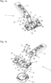
- Fig. 1a shows a hinge 1 in the form of a furniture hinge, comprising a stop part 2, with which the hinge 1 can be fastened to a fixed furniture part 40 (see FIG 7 ), two articulated levers 3, with a first articulated lever 3 covering a further articulated lever 39 in the illustration, and a hinge cup 4, which is pivotably arranged on the stop part 2 via the two articulated levers 3.
- the articulated lever 3 (and the further articulated lever 39) is mounted with the hinge cup 4 via articulation axes 5, with the hinge cup 4 being able to be fastened to a movable furniture part 41.
- Fig. 1b shows an exploded view of the components involved in the hinge 1, with one actuating element 12 being designed as a sheet metal part 25 bent in a U-shape.
- the actuating element 12 can, however, in general (for example in the exemplary embodiment according to Figure 5a ) be designed as a plastic part.
- the hinge 1 comprises a damping device 6 for damping a relative movement between the stop part 2 and the hinge cup 4 between an open position 7 and a closed position 8 of the hinge 1, which is arranged laterally on the hinge cup 4 on the outside.
- the damping device 6 has a linear damper 9 with a piston 10 and a piston rod 11 that can be moved translationally relative to the linear damper 9 , the piston rod 11 being connected to the piston 10 for damping the hinge 1 .
- the joint axis 5, which is more relevant for the transmission of the damping movement, is illustrated as axis 22 in the figures.
- a further damping device 6 can also be provided, which is arranged on the hinge cup 4 symmetrically or mirrored about a longitudinal extension of the hinge 1 .
- the hinge 1 comprises a one-piece and separate actuating element 12 for actuating the at least one damping device 6 , which is spatially spaced from the articulated lever 3 in the open position 7 and contacts the articulated lever 3 in the closed position 8 .
- the damping device 6 is arranged completely outside of the hinge cup 4 .
- FIG. 2a shows the arrangement of the damping device 6 and the actuating element 12 relative to a hinge cup cover 13, with which the damping device 6 and the actuating element 12 can be covered.
- the hinge cup cover 13 has on a lateral surface facing the articulated lever 3 fastening means with which the hinge cup cover 13 can be clipped onto the hinge cup 4, with a receiving area 14 being provided which adapts to the geometry of the Damping device 6 and the actuating element 12 is configured correspondingly.
- Figure 2b shows the arrangement Figure 2a in a sectional view through the middle of the hinge cup cover 13.
- the hinge cup cover 13 has a further bearing surface 44 on which the damping device 6 can be supported when the hinge 1 is in the position of use.
- Figure 2c shows the hinge 1 without the hinge cup cover 13, the hinge cup 4 comprising a recess 18, a hinge cup bottom 19 and a bearing surface 20, the damping device 6 being arranged in the recess 18 of the hinge cup 4 and on the bearing surface 20 of the hinge cup 4.
- the bearing surface 20 encloses an acute angle 21 with respect to the hinge cup base 19 .
- the bearing surface 20 can be oriented parallel to the further bearing surface 44 of the hinge cup cover 13, so that the damping device 6 has a firm seat on the hinge cup 4, or it can be arranged relative to the further bearing surface 44 in such a way that a slight rotational movement of the damping device 6 is made possible, which is superimposed with a translational movement of the piston rod 11.
- the bearing surface 20 or the further bearing surface 44 is not absolutely necessary.
- the actuating element 12 protrudes through a hinge cup opening 45 into the hinge cup 4, it also generally being possible for the actuating element 12 to be arranged exclusively outside the hinge cup 4 and the articulated lever 3 to protrude through the hinge cup opening 45 out of the hinge cup 4, with the articulated lever 3 is arranged in some areas inside and in some areas outside of the hinge cup 4 . It is generally also conceivable that the actuating element 12 by the Articulated lever 3 is formed and the rotational movement is transmitted directly to the piston rod 11 of the damping device 6 .
- the rotational movement of the actuating element 12 is picked up by the piston rod 11 on the profile 24, it being possible for a transmission ratio to be changed by changing the spacing of the profile 24 from the axis 22.
- the rotational movement of the articulated lever 3 is tapped off by the actuating element 12 on the coupling device 29, a translation being able to be changed by changing the spacing of the coupling device 29 from the axis 22 (or the positioning of the transmission device 26 on the articulated lever 3).
- the rotational movement is preferably scanned at a free end of the articulated lever 3 and/or the actuating element 12.
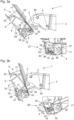
- Figure 3a shows that the actuating element 12 is arranged on the hinge cup 4 in some areas inside and in some areas outside the hinge cup 4 .
- the actuating element 12 is rotatably mounted on the hinge cup 4 on the outside via the joint axis 5 in the form of the axis 22 (formed by a clamp 37).
- the piston rod 11 can be moved translationally relative to the linear damper 9 directly by rotating the actuating element 12 (possibly with a slight pivoting movement of the piston rod 11 and the linear damper 9).
- the hinge 1 includes a transmission device 26, with which a rotational movement of the articulated lever 3 on the actuating element 12 can be implemented.
- the transmission device is arranged inside the hinge cup 4 .
- the transmission device 26 is designed without contact with the actuating element 12 in a first movement section 27, with the hinge 1 being present in the first movement section 27 in the state shown.
- the transmission device 26 is in contact with the actuating element 12 in the direction of the closed position 8 of the hinge 1 (see FIG Figure 3b ).
- the transmission device 26 comprises a cam 23 and a profile 24 in the form of an undercut 43 for receiving the actuating element 12.
- FIG 3b shows the hinge 1 at the beginning of the second movement section 12, the damping device 6 being active through the transmission device 26 exclusively in the second movement section 28.
- the articulated lever 3 is arranged in regions within the hinge cup 4 in an interior space 15 of the hinge cup 4 .
- An outer space 16 of the hinge cup 4 is separated from the inner space 15 of the hinge cup 4 by a hinge cup wall 17 that is separate from the hinge cup cover 13 and spaced from the hinge cup cover 13 in some areas.
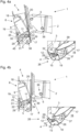
- Figure 4a shows that the actuating element 12 is mounted on the hinge pot 4 such that it can rotate about the axis 22 in the form of one of the joint axes 5 .
- the rotational movement of the actuating element 12 can be translated into a linear movement of the piston rod 11 of the linear damper 9 .
- the actuating element 12 comprises a convex in the direction of the piston rod 11 trained cam 23 and a convex profile 24 in the direction of the piston 10 of the linear damper 9.
- the transmission device 26 which is rotatably positioned on the axis 22, is designed as a materially connected part of the articulated lever 3 and is therefore an integral part of the articulated lever 3. In general, however, the transmission device 26 can also be designed as a separate structural component of the hinge 1 or can interact indirectly with the articulated lever 3 stand.
- the articulated lever 3 rotates in the first movement segment 27 about the joint axis 5 until the transmission device 26 contacts the actuating element 12 and during the second movement segment 28 the actuating element 12 rotates in a motion-coupled manner in order to initiate damping via the piston rod 11.
- this movement coupling for damping the hinge 1 is also possible as an alternative or in addition in the course of an opening movement of the hinge 1 .
- the actuating element 12 is for the most part outside (in the outer space 16) of the hinge cup 4 and protrudes into the interior 15 of the hinge cup 4.
- the actuating element 12 comprises a coupling device 29 with which the transmission device 26 for damping the hinge 1 can be contacted.
- the coupling device 29 is designed in the form of a web 30 oriented parallel to the joint axes 5 , the web 30 projecting transversely from the actuating element 12 .
- the coupling device 29 protrudes through a slot 32 in the form of a circular ring segment 31 as a hinge cup opening 45 into the hinge cup 4 .
- the coupling device 29 has a free end 33 .
- Figure 4b differs from Figure 4a only to the effect that the hinge 1 is in the closed position 8 .
- the damping stroke of the damping device 6 has ended, it being possible in general for the damping device 6 to be returned to an initial position of the damping device 6 by means of a return spring or via a movement coupling with the actuating element 12 .
- FIG. 12 shows another preferred exemplary embodiment of the hinge 1 in an exploded view, with the actuating element 12 being connected to the piston rod 11 via an extension rod 34 arranged orthogonally to the piston rod 11 .
- the extension rod 34 of the piston rod 11 is arranged in regions within an opening 35 of the actuating element 12 for movement coupling of the piston rod 11 to the actuating element 12 .
- the opening 35 can generally also be designed as a depression for arranging the extension rod 34 on the actuating element 12 .
- Two of the hinge pins 5 are in the form of a rivet 36 connected to the hinge cup 4 , two of the hinge pins 5 being designed as a clamp 37 connected to the hinge cup 4 .
- the clip 37 forms the axis 22 and a further joint axis 38 for a further joint lever 39.
- the axis 22 can generally also be formed by a rivet 36.
- Figure 5b shows that the articulated lever 3 includes the transmission device 26 .
- the articulated lever 3 it is possible for the articulated lever 3 to be arranged indirectly via the transmission device 26 on the actuating element 12 by a rotational movement of the articulated lever 3 .
- Figure 6a shows the hinge in the second movement section 28, with a rotation of the articulated lever 3 via the coupling device 29 on the Actuating element 12 is transmitted and by the arrangement of the extension rod 34 in the opening 35, the piston rod 11 is moved in translation for damping.
- the linear movement can be superimposed with a rotation of the damping device 6 .
- Figure 6b differs from Figure 6b only to the effect that the hinge is in the closed position 8.
- An end of the damping stroke of the damping device 6 can be generated, for example, by the articulated lever 3 making contact with the hinge cup 4 and/or by a stop of the elongated hole 32 .
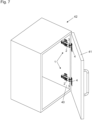
- FIG. 7 shows a piece of furniture 42 comprising a fixed furniture part 40 and a furniture part 41 movably mounted on the fixed furniture part 40 with two hinges 1, the stop part 2 of the hinge 1 being arranged on the fixed furniture part 40.
- the hinge cup 4 of the hinge 1 is arranged on the movable furniture part 41 , the hinge cup 4 being integrated into the movable furniture part 41 .
- the hinge 1 is not limited to use with furniture 42.
- the hinge 1 can, for example, also be used in an analogous manner in a window or a door.
Landscapes
- Engineering & Computer Science (AREA)
- Mechanical Engineering (AREA)
- Hinges (AREA)
Priority Applications (7)
| Application Number | Priority Date | Filing Date | Title |
|---|---|---|---|
| EP21214287.1A EP4198230A1 (fr) | 2021-12-14 | 2021-12-14 | Charnière |
| EP22830532.2A EP4448903A1 (fr) | 2021-12-14 | 2022-12-06 | Charnière |
| CN202280082354.8A CN118434952A (zh) | 2021-12-14 | 2022-12-06 | 铰链 |
| PCT/EP2022/084579 WO2023110536A1 (fr) | 2021-12-14 | 2022-12-06 | Charnière |
| JP2024535596A JP7733833B2 (ja) | 2021-12-14 | 2022-12-06 | ヒンジ |
| KR1020247021064A KR102989366B1 (ko) | 2021-12-14 | 2022-12-06 | 힌지 |
| US18/739,952 US12655670B2 (en) | 2021-12-14 | 2024-06-11 | Hinge |
Applications Claiming Priority (1)
| Application Number | Priority Date | Filing Date | Title |
|---|---|---|---|
| EP21214287.1A EP4198230A1 (fr) | 2021-12-14 | 2021-12-14 | Charnière |
Publications (1)
| Publication Number | Publication Date |
|---|---|
| EP4198230A1 true EP4198230A1 (fr) | 2023-06-21 |
Family
ID=78851150
Family Applications (2)
| Application Number | Title | Priority Date | Filing Date |
|---|---|---|---|
| EP21214287.1A Pending EP4198230A1 (fr) | 2021-12-14 | 2021-12-14 | Charnière |
| EP22830532.2A Pending EP4448903A1 (fr) | 2021-12-14 | 2022-12-06 | Charnière |
Family Applications After (1)
| Application Number | Title | Priority Date | Filing Date |
|---|---|---|---|
| EP22830532.2A Pending EP4448903A1 (fr) | 2021-12-14 | 2022-12-06 | Charnière |
Country Status (6)
| Country | Link |
|---|---|
| US (1) | US12655670B2 (fr) |
| EP (2) | EP4198230A1 (fr) |
| JP (1) | JP7733833B2 (fr) |
| KR (1) | KR102989366B1 (fr) |
| CN (1) | CN118434952A (fr) |
| WO (1) | WO2023110536A1 (fr) |
Families Citing this family (1)
| Publication number | Priority date | Publication date | Assignee | Title |
|---|---|---|---|---|
| DE102022127874A1 (de) * | 2022-10-21 | 2024-05-02 | Grass Gmbh | Scharnier, insbesondere für Kühlschranktüren |
Citations (5)
| Publication number | Priority date | Publication date | Assignee | Title |
|---|---|---|---|---|
| DE20320810U1 (de) * | 2002-08-29 | 2005-04-21 | Julius Blum Gmbh | Scharnier |
| EP1359275B1 (fr) * | 2002-04-30 | 2012-08-22 | Zimmer, Günther Stephan | Charnière avec dispositif pour amortir des mouvements rotatifs |
| WO2016102215A1 (fr) | 2014-12-23 | 2016-06-30 | Arturo Salice S.P.A. | Charnière à décélération pour meubles |
| DE202015105233U1 (de) * | 2015-10-05 | 2017-01-09 | Grass Gmbh & Co. Kg | Scharnier für ein an einem Korpus eines Möbels angeschlagenes bewegbares Möbelteil |
| EP2411612B1 (fr) * | 2009-03-25 | 2018-09-12 | Julius Blum GmbH | Charnière de meuble |
Family Cites Families (16)
| Publication number | Priority date | Publication date | Assignee | Title |
|---|---|---|---|---|
| AT502613B1 (de) * | 2003-04-15 | 2007-08-15 | Blum Gmbh Julius | Dämpfer mit gehäuse |
| AT502487B1 (de) * | 2005-10-06 | 2007-04-15 | Blum Gmbh Julius | Dämpferanordnung |
| DE202006013358U1 (de) | 2006-08-31 | 2008-01-03 | Hettich-Oni Gmbh & Co. Kg | Möbelscharnier |
| ITMI20072169A1 (it) * | 2007-11-14 | 2009-05-15 | Agostino Ferrari Spa | "gruppo ammortizzatore per cerniere di mobili" |
| AT506520B1 (de) * | 2008-02-25 | 2012-10-15 | Blum Gmbh Julius | Scharnier für bewegbare möbelteile |
| AT507697B1 (de) | 2008-12-17 | 2011-12-15 | Blum Gmbh Julius | Möbelscharnier mit rotationsdämpfer |
| AT508068B1 (de) | 2009-03-25 | 2016-11-15 | Blum Gmbh Julius | Möbelscharnier |
| AT15271U1 (de) | 2012-02-16 | 2017-04-15 | Blum Gmbh Julius | Möbelscharnier |
| AT14690U1 (de) | 2012-09-28 | 2016-04-15 | Blum Gmbh Julius | Dämpfer für bewegbare Möbelteile |
| CN103306561A (zh) * | 2013-06-05 | 2013-09-18 | 广东亚当斯金属制造有限公司 | 一种斜压式家具缓冲铰链 |
| US9169681B2 (en) * | 2014-01-31 | 2015-10-27 | Hardware Resources, Inc. | Low profile adjustable soft close hinge apparatus |
| DE102014106911A1 (de) * | 2014-05-16 | 2015-11-19 | Hettich-Oni Gmbh & Co. Kg | Scharnier für Möbel oder Haushaltsgeräte |
| GB2550948A (en) * | 2016-06-02 | 2017-12-06 | Titus D O O Dekani | Improvements in damped hinge assemblies |
| PL3580420T3 (pl) * | 2017-02-13 | 2023-05-02 | Samet Kalip Ve Madeni Esya San. Ve Tic. A.S. | Zawias meblowy z elementem blokującym do amortyzatora liniowego |
| GB2581396A (en) | 2019-02-18 | 2020-08-19 | Titus D O O Dekani | Improvements in hinge assemblies |
| GB2603002A (en) * | 2021-01-25 | 2022-07-27 | Titus D O O Dekani | Hinge assembly |
-
2021
- 2021-12-14 EP EP21214287.1A patent/EP4198230A1/fr active Pending
-
2022
- 2022-12-06 EP EP22830532.2A patent/EP4448903A1/fr active Pending
- 2022-12-06 KR KR1020247021064A patent/KR102989366B1/ko active Active
- 2022-12-06 CN CN202280082354.8A patent/CN118434952A/zh active Pending
- 2022-12-06 JP JP2024535596A patent/JP7733833B2/ja active Active
- 2022-12-06 WO PCT/EP2022/084579 patent/WO2023110536A1/fr not_active Ceased
-
2024
- 2024-06-11 US US18/739,952 patent/US12655670B2/en active Active
Patent Citations (5)
| Publication number | Priority date | Publication date | Assignee | Title |
|---|---|---|---|---|
| EP1359275B1 (fr) * | 2002-04-30 | 2012-08-22 | Zimmer, Günther Stephan | Charnière avec dispositif pour amortir des mouvements rotatifs |
| DE20320810U1 (de) * | 2002-08-29 | 2005-04-21 | Julius Blum Gmbh | Scharnier |
| EP2411612B1 (fr) * | 2009-03-25 | 2018-09-12 | Julius Blum GmbH | Charnière de meuble |
| WO2016102215A1 (fr) | 2014-12-23 | 2016-06-30 | Arturo Salice S.P.A. | Charnière à décélération pour meubles |
| DE202015105233U1 (de) * | 2015-10-05 | 2017-01-09 | Grass Gmbh & Co. Kg | Scharnier für ein an einem Korpus eines Möbels angeschlagenes bewegbares Möbelteil |
Also Published As
| Publication number | Publication date |
|---|---|
| WO2023110536A1 (fr) | 2023-06-22 |
| KR102989366B1 (ko) | 2026-07-13 |
| JP7733833B2 (ja) | 2025-09-03 |
| US20240328227A1 (en) | 2024-10-03 |
| US12655670B2 (en) | 2026-06-16 |
| EP4448903A1 (fr) | 2024-10-23 |
| CN118434952A (zh) | 2024-08-02 |
| KR20240114760A (ko) | 2024-07-24 |
| JP2024546880A (ja) | 2024-12-26 |
Similar Documents
| Publication | Publication Date | Title |
|---|---|---|
| EP1359275B1 (fr) | Charnière avec dispositif pour amortir des mouvements rotatifs | |
| EP2815050B1 (fr) | Charnière pour meuble | |
| EP2796650B1 (fr) | Charnière de meuble | |
| EP2411612B1 (fr) | Charnière de meuble | |
| EP2622160B1 (fr) | Ferrure pour meubles et meuble | |
| DE102019113337B4 (de) | Möbelbeschlag | |
| EP2450513B1 (fr) | Penture de meuble et meuble | |
| DE202010015091U1 (de) | Möbelbeschlag und Möbel | |
| EP4244456B1 (fr) | Ferrure de meuble pour le montage mobile d'un élément de meuble | |
| EP3973126A1 (fr) | Ferrure de meuble | |
| EP4466436B1 (fr) | Meuble | |
| WO2016177559A1 (fr) | Charnière de meuble dotée d'un amortisseur | |
| EP3359764B1 (fr) | Charnière de meuble | |
| DE102015106917A1 (de) | Möbelscharnier mit einem Dämpfer und einer Feder | |
| EP4466435B1 (fr) | Meuble | |
| EP4198237B1 (fr) | Charnière | |
| EP2251514B1 (fr) | Compas pour vantail | |
| WO2023110536A1 (fr) | Charnière | |
| EP2492427B1 (fr) | Dispositif de ferrure pour un élément de meuble mobile | |
| DE202013102641U1 (de) | Beschlag für Fenster oder Türen | |
| DE102004034247B3 (de) | Türscharnier für Kraftfahrzeuge | |
| EP3585964A1 (fr) | Dispositif d'actionnement manuel comprenant un élément d'arrêt | |
| EP2665613A1 (fr) | Dispositif de déplacement pour un élément d'équipement intérieur de véhicule automobile et élément d'équipement intérieur | |
| EP4636208A2 (fr) | Ferrure pour le montage mobile d'un élément pivotant | |
| EP4077843A1 (fr) | Ensemble de guidage servant à guider au moins une partie de meuble mobile |
Legal Events
| Date | Code | Title | Description |
|---|---|---|---|
| PUAI | Public reference made under article 153(3) epc to a published international application that has entered the european phase |
Free format text: ORIGINAL CODE: 0009012 |
|
| STAA | Information on the status of an ep patent application or granted ep patent |
Free format text: STATUS: REQUEST FOR EXAMINATION WAS MADE |
|
| 17P | Request for examination filed |
Effective date: 20220630 |
|
| AK | Designated contracting states |
Kind code of ref document: A1 Designated state(s): AL AT BE BG CH CY CZ DE DK EE ES FI FR GB GR HR HU IE IS IT LI LT LU LV MC MK MT NL NO PL PT RO RS SE SI SK SM TR |
|
| P01 | Opt-out of the competence of the unified patent court (upc) registered |
Effective date: 20230803 |
|
| STAA | Information on the status of an ep patent application or granted ep patent |
Free format text: STATUS: EXAMINATION IS IN PROGRESS |
|
| 17Q | First examination report despatched |
Effective date: 20250814 |