EP4198271B1 - Séparateur de gaz de carter - Google Patents
Séparateur de gaz de carter Download PDFInfo
- Publication number
- EP4198271B1 EP4198271B1 EP21215528.7A EP21215528A EP4198271B1 EP 4198271 B1 EP4198271 B1 EP 4198271B1 EP 21215528 A EP21215528 A EP 21215528A EP 4198271 B1 EP4198271 B1 EP 4198271B1
- Authority
- EP
- European Patent Office
- Prior art keywords
- separator
- joint
- gas
- tube member
- separate tube
- Prior art date
- Legal status (The legal status is an assumption and is not a legal conclusion. Google has not performed a legal analysis and makes no representation as to the accuracy of the status listed.)
- Active
Links
Images


Classifications
-
- F—MECHANICAL ENGINEERING; LIGHTING; HEATING; WEAPONS; BLASTING
- F01—MACHINES OR ENGINES IN GENERAL; ENGINE PLANTS IN GENERAL; STEAM ENGINES
- F01M—LUBRICATING OF MACHINES OR ENGINES IN GENERAL; LUBRICATING INTERNAL COMBUSTION ENGINES; CRANKCASE VENTILATING
- F01M13/00—Crankcase ventilating or breathing
- F01M13/04—Crankcase ventilating or breathing having means for purifying air before leaving crankcase, e.g. removing oil
-
- B—PERFORMING OPERATIONS; TRANSPORTING
- B01—PHYSICAL OR CHEMICAL PROCESSES OR APPARATUS IN GENERAL
- B01D—SEPARATION
- B01D45/00—Separating dispersed particles from gases or vapours by gravity, inertia, or centrifugal forces
- B01D45/12—Separating dispersed particles from gases or vapours by gravity, inertia, or centrifugal forces by centrifugal forces
- B01D45/14—Separating dispersed particles from gases or vapours by gravity, inertia, or centrifugal forces by centrifugal forces generated by rotating vanes, discs, drums or brushes
-
- F—MECHANICAL ENGINEERING; LIGHTING; HEATING; WEAPONS; BLASTING
- F01—MACHINES OR ENGINES IN GENERAL; ENGINE PLANTS IN GENERAL; STEAM ENGINES
- F01M—LUBRICATING OF MACHINES OR ENGINES IN GENERAL; LUBRICATING INTERNAL COMBUSTION ENGINES; CRANKCASE VENTILATING
- F01M13/00—Crankcase ventilating or breathing
- F01M13/04—Crankcase ventilating or breathing having means for purifying air before leaving crankcase, e.g. removing oil
- F01M2013/0422—Separating oil and gas with a centrifuge device
Definitions
- Crankcase gas is ventilated from a crankcase of an internal combustion engine, ICE.
- Crankcase gases may be disposed of in an environmentally friendly manner instead of being ventilated in untreated form to the atmosphere.
- legislation even requires crankcase gases to be disposed of in an environmentally friendly manner.
- Crankcase gases may comprise inter alia blow-by gases, oil, other liquid hydrocarbons, soot, and other solid combustion residues.
- the gas is separated from oil, soot, and other residues.
- the separated gas may be led to an air intake of the combustion engine or vented to the atmosphere, and the oil may be led back to an oil sump of the combustion engine optionally, via an oil filter for removing soot and other solid residues from the oil.
- a centrifugal separator may be used for disposing of crankcase gas.
- the crankcase gas is led into a rotor of the centrifugal separator and heavy constituents of the crankcase gases, such as oil and soot, are separated as a liquid phase from a cleaned gaseous phase.
- the liquid phase is led out of the centrifugal separator via a liquid outlet.
- the gaseous phase is lead out of the centrifugal separator via a gas outlet and may be directed to an air intake of the ICE.
- Prior art crankcase gas separators may rely on one or more O-rings to seal a gas passage extending from the separation space of the separator to the gas pressure regulating valve.
- O-rings for sealing a passage from a separation space of a crankcase gas separator to a gas pressure regulating valve is that O-rings may be cumbersome to mount during assembly of the separator.
- crankcase gas separator it is an object of the invention to prevent a separated liquid phase from entering a gas pressure regulating valve of the separator.
- the rotor may comprise a separation aid e.g., a number of separating members, which improve the separation of the heavy constituents from the crankcase gas.
- the separation aid may comprise separating members in the form of e.g., axially extending vanes which are directed radially from the rotor shaft or stacked frustoconical separation discs. As the rotor rotates, the heavy constituents are forced against radially inwardly facing surfaces of the separating members whereon droplets of the separated phase are formed and flow towards the outer periphery of the rotor.
- the separate tube member extends from the position radially inside the inner wall surface, an inner opening of the separate tube member is arranged at a radial distance from the inner wall surface. Thus, the liquid phase flowing along the inner wall surface cannot reach the inner opening of the separate tube member.
- the joint may be a welded joint. In this manner, a liquid tight joint may be provided between the separate tube member and the wall member in a convenient manner.
- a press fitted joint may be provided in an automated step of a manufacturing process of the separator, in which automated step the separate tube member is pressed into the wall member.
- the mechanically interlocking joint may be provided in an automated step of a manufacturing process of the separator.
- the separate tube member may be made from a rubber material.
- the separate tube member may have elastic properties, which may be advantageous to achieve the liquid tight seal.
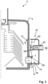
- a rotor shaft 18 extends through the separation space 6 in an axial direction.
- a rotor 20 wherein the crankcase gas is separated into the liquid phase and the gaseous phase is arranged inside the separation space 6.
- the rotor 20 is connected to the rotor shaft 18.
- the liquid phase receiving circumferential inner wall surface 12 extends circumferentially around the rotor 20 and the droplets of separated liquid phase received on the inner wall surface 12 are separated in the rotor 20.
- the rotor shaft 18 is journalled in the separator housing 4.
- the rotor shaft 18 may be journaled e.g., in ball bearings, roller bearings, or plain bearings.
- the gas passage 14 is arranged at a lower end portion of the separation space 6.
- the rotor 20 comprises a separation aid in the form of a stack 26 of separation discs 28, each separation disc 28 having a frustoconical, shape. Between the separation discs 28 in the stack 26, interspaces are formed through which the crankcase gas travels from an inner periphery towards an outer periphery while being separated into the liquid phase and the gaseous phases as the rotor 20 rotates. In Fig. 1 only some of the separation discs 28 are indicated.
- separation aids may be utilised, such as e.g. axially extending vanes projecting radially outwardly from the rotor shaft.
- crankcase gas, gaseous phase, and liquid phase through the separator 2 is indicated with small arrows in Fig. 1 .
- a liquid tight seal between the separate tube member 34 and the wall member 8 is formed by a joint 38 arranged radially outside the inner wall surface 12.
- the joint 38 is schematically indicated in Fig. 1 .
- the invention is not limited to any particular kind of joint 38, as long as a liquid tight seal is provided by the joint 38.
- the joint 38 may for instance be a glue joint. That is, a glue, an adhesive, or a resin may form the joint 38 between the tube member 34 and the wall member 8.
- a glue, adhesive, or resin suitably is oil resistant i.e., oil cannot dissolve the joint 38, in order to ensure the liquid tight seal provided by the joint 38.
- the joint 38 may be a press fitted joint. That is, the tube member 34 has a slightly larger outer diameter than an inner diameter of the wall member 8. Thus, a press fit is achieved between the tube member 34 and the wall member 8, which provides the liquid tight seal.
- the joint 38 may form the only liquid tight seal between the separate tube member 34 and the wall member 8. In this manner, only the joint 38 has to be provided in the separator 2 to ensure that no liquid phase leaks from the separation space 6 into the gas pressure regulating valve 10.
- the separate tube member 34 may be made from a same material as the wall member 8. In this manner, the separate tube member 34 and the wall member 8 may have the same or at least similar properties.
- the separate tube member 34 and the wall member 8 may have a same temperature coefficient.
- the separate tube member 34 and the wall member 8 may expand and contract due to temperature changes without shifting their positional relationship.
- the material of the separate tube member 34 and the wall member 8 is a weldable material, such as a thermoplastic material, forming the separate tube member 34 and the wall member 8 from the same material provides the possibility for the joint 38 to be a welded joint.
- the separate tube member 34 may be made from a different material than the wall member 8. In this manner, different material properties may be utilised for providing a liquid tight joint 38.
- the separate tube member 34 may be made from a rubber material. In this manner, the elastic properties of the rubber material may be utilised to provide the liquid tight joint 38 between the separate tube member 34 and the wall member 8.
- the rubber material may comprise one or more of natural rubber, synthetic rubber such as EPDM, silicone, or a thermoplastic elastomer.
- Figs. 2a and 2b schematically illustrate cross sections through a portion of respective crankcase gas separators 2 according to embodiments. These embodiments are similar to the embodiments shown in Fig. 1 . Accordingly, in the following mainly the differences between the Fig. 1 embodiments and the Fig. 2a and 2b embodiments are discussed.
- the separator 2 comprises a separate tube member 34 extending from a position 36 radially inside the inner wall surface 12 into the gas passage 14.
- a portion of the gas passage 14 extends through the tube member 34.
- a liquid tight seal between the separate tube member 34 and the wall member 8 is formed by a joint 38 arranged radially outside the inner wall surface 12.
- the tube member 34 is provided with a circumferentially facing opening 40, though which the separated gaseous phase will flow from the position 36 within the separation space 6 into the separate tube member 34 and the gas passage 14.
- the joint 38 may be a welded joint between the separate tube member 34 and the wall member 8, which welded joint extends in a radial direction of the tube member 34.
- the joint 38 is a mechanically interlocking joint.
- Exemplified as a mechanically interlocking joint in these embodiments is a threaded engagement between the tube member 34 and the wall member 8.
- press fitted joint may be an example of a mechanically interlocking joint, depending on how tight the press fit of the joint is.
- the separate tube member 34 extends into the gas channel 46, the separate tube member 34 ensures that the separate gaseous phase flows through the gas channel 46 and exits the separation space 6 at the specific position within the separation space 6.
- joints may alternatively be provided between the tube member 34 and the gas channel forming member 44, such as a welded joint, a glued joint, or a press fitted joint.
- the separator 2 comprises: a separator housing 4 delimiting at least part of a separation space 6 and forming at least part of a liquid phase receiving circumferential inner wall surface 12, the wall member 8 forming at least part of a gas passage 14, and the separate tube member 34.
- a liquid tight seal is formed by a joint 38 between the separate tube member 34 and the wall member 8.
- valve 10 is shown in an open state and the flow of the separated gaseous phase through the gas passage 14 and the valve 10 to a gas outlet 35 of the separator 2 is indicated with arrows.
- At least part of a housing of the valve 10 may form part of the separator housing 4. Accordingly, the gas passage 14 may be formed in the separator housing 4 and optionally, also in a housing of the valve 10.
Landscapes
- Engineering & Computer Science (AREA)
- Mechanical Engineering (AREA)
- General Engineering & Computer Science (AREA)
- Chemical & Material Sciences (AREA)
- Chemical Kinetics & Catalysis (AREA)
- Lubrication Details And Ventilation Of Internal Combustion Engines (AREA)
Claims (13)
- Séparateur de gaz de carter (2), comprenant un boîtier de séparateur (4) délimitant au moins une partie d'un espace de séparation (6) et formant au moins une partie d'une surface de paroi interne circonférentielle (12) de réception de phase liquide, un élément de paroi (8) formant au moins une partie d'un passage de gaz (14) et une soupape de régulation de la pression du gaz (10) comprenant au moins une partie du passage de gaz (14), dans lequel :l'espace de séparation (6) est agencé en communication de fluide avec le passage de gaz (14) ;caractérisé en ce que :
le séparateur (2) comprend un élément de tube séparé (34) s'étendant depuis une position (36) située radialement à l'intérieur de la surface de paroi interne (12) dans le passage de gaz (14) ; dans lequel :
un joint étanche aux liquides entre l'élément de tube séparé (34) et l'élément de paroi (8) est formé par un raccord (38) agencé radialement à l'extérieur de la surface de paroi interne (12). - Séparateur (2) selon la revendication 1, dans lequel le raccord (38) est un raccord soudé.
- Séparateur (2) selon les revendications 1 ou 2, dans lequel le raccord (38) est un raccord ajusté par pression.
- Séparateur (2) selon l'une quelconque des revendications précédentes, dans lequel le raccord (38) est un raccord à interverrouillage mécanique.
- Séparateur (2) selon la revendication 1, dans lequel le raccord (38) est un raccord collé.
- Séparateur (2) selon l'une quelconque des revendications précédentes, dans lequel le raccord (38) forme le seul joint étanche aux liquides entre l'élément de tube séparé (34) et l'élément de paroi (8).
- Séparateur (2) selon l'une quelconque des revendications précédentes, dans lequel l'élément de tube séparé (34) est fabriqué à partir d'un même matériau que l'élément de paroi (8).
- Séparateur (2) selon l'une quelconque des revendications 1 à 6, dans lequel l'élément de tube séparé (34) est fabriqué à partir d'un matériau différent de celui de l'élément de paroi (8).
- Séparateur (2) selon la revendication 8, dans lequel l'élément de tube séparé (34) est fabriqué à partir d'un matériau de caoutchouc.
- Séparateur (2) selon l'une quelconque des revendications précédentes, comprenant un élément formant un canal de gaz (44) agencé à l'intérieur du boîtier de séparateur (4), dans lequel un canal de gaz (46) s'étend à travers l'élément formant le canal de gaz (44), et dans lequel l'élément de tube séparé (34) s'étend dans le canal de gaz (46).
- Séparateur (2) selon la revendication 10, dans lequel l'élément de tube séparé (34) établit l'étanchéité contre l'élément formant le canal de gaz (44).
- Séparateur (2) selon l'une quelconque des revendications précédentes, dans lequel la soupape de régulation de la pression du gaz (10) comprend un siège de soupape (48) et une membrane (50) configurée pour établir l'étanchéité contre le siège de soupape (48), et dans lequel le passage de gaz (14) s'étend au moins en amont du siège de soupape (48).
- Séparateur (2) selon l'une quelconque des revendications précédentes, dans lequel, dans une position opérationnelle du séparateur (2), le passage de gaz (14) est agencé au niveau d'une partie d'extrémité inférieure de l'espace de séparation (6).
Priority Applications (4)
| Application Number | Priority Date | Filing Date | Title |
|---|---|---|---|
| EP21215528.7A EP4198271B1 (fr) | 2021-12-17 | 2021-12-17 | Séparateur de gaz de carter |
| US18/713,836 US12241391B2 (en) | 2021-12-17 | 2022-11-25 | Crankcase gas separator |
| CN202280082391.9A CN118401745A (zh) | 2021-12-17 | 2022-11-25 | 曲轴箱气体分离器 |
| PCT/EP2022/083291 WO2023110364A1 (fr) | 2021-12-17 | 2022-11-25 | Séparateur de gaz de carter |
Applications Claiming Priority (1)
| Application Number | Priority Date | Filing Date | Title |
|---|---|---|---|
| EP21215528.7A EP4198271B1 (fr) | 2021-12-17 | 2021-12-17 | Séparateur de gaz de carter |
Publications (2)
| Publication Number | Publication Date |
|---|---|
| EP4198271A1 EP4198271A1 (fr) | 2023-06-21 |
| EP4198271B1 true EP4198271B1 (fr) | 2024-07-10 |
Family
ID=78957250
Family Applications (1)
| Application Number | Title | Priority Date | Filing Date |
|---|---|---|---|
| EP21215528.7A Active EP4198271B1 (fr) | 2021-12-17 | 2021-12-17 | Séparateur de gaz de carter |
Country Status (4)
| Country | Link |
|---|---|
| US (1) | US12241391B2 (fr) |
| EP (1) | EP4198271B1 (fr) |
| CN (1) | CN118401745A (fr) |
| WO (1) | WO2023110364A1 (fr) |
Family Cites Families (11)
| Publication number | Priority date | Publication date | Assignee | Title |
|---|---|---|---|---|
| SE527934C2 (sv) | 2004-06-03 | 2006-07-11 | Alfa Laval Corp Ab | En anordning och ett förfarande för rening av en gas |
| DE102005025864A1 (de) | 2005-06-06 | 2006-12-07 | Robert Bosch Gmbh | Vorrichtung zur Abscheidung von Flüssigkeit aus einem Gasstrom |
| SE528701C2 (sv) * | 2005-06-08 | 2007-01-30 | Alfa Laval Corp Ab | Centrifugalseparator för rening av en gas |
| EP2252776B1 (fr) * | 2008-03-18 | 2019-01-16 | Volvo Lastvagnar AB | Procédé de diagnostic fonctionnel d'un séparateur |
| DE202008014734U1 (de) | 2008-11-06 | 2010-03-25 | Hengst Gmbh & Co.Kg | Zentrifugalabscheider |
| CN104234782B (zh) | 2014-09-18 | 2016-09-21 | 中国第一汽车股份有限公司 | 一种集成离心式滤清器功能的主动式油气分离器 |
| EP3103554B1 (fr) * | 2015-06-10 | 2018-03-14 | Alfdex AB | Séparateur par centrifugation |
| EP3112034B1 (fr) | 2015-07-03 | 2024-06-05 | Alfdex AB | Structure et ensemble séparateur centrifuge |
| DE202016101388U1 (de) | 2016-02-04 | 2017-05-05 | Elringklinger Ag | Abscheidevorrichtung |
| DE202016104755U1 (de) | 2016-08-30 | 2017-12-04 | Reinz-Dichtungs-Gmbh | Ölabscheider, Entlüftungssystem und Verbrennungsmotor |
| CN111734513A (zh) * | 2020-07-10 | 2020-10-02 | 江苏宝时达动力科技有限公司 | 一种燃油发动机用油气分离装置 |
-
2021
- 2021-12-17 EP EP21215528.7A patent/EP4198271B1/fr active Active
-
2022
- 2022-11-25 WO PCT/EP2022/083291 patent/WO2023110364A1/fr not_active Ceased
- 2022-11-25 CN CN202280082391.9A patent/CN118401745A/zh active Pending
- 2022-11-25 US US18/713,836 patent/US12241391B2/en active Active
Also Published As
| Publication number | Publication date |
|---|---|
| US12241391B2 (en) | 2025-03-04 |
| CN118401745A (zh) | 2024-07-26 |
| WO2023110364A1 (fr) | 2023-06-22 |
| EP4198271A1 (fr) | 2023-06-21 |
| US20250035020A1 (en) | 2025-01-30 |
Similar Documents
| Publication | Publication Date | Title |
|---|---|---|
| US7011690B2 (en) | Device for separating liquid from a gas current | |
| US6261455B1 (en) | Centrifuge cartridge for removing soot from oil in vehicle engine applications | |
| RU2669631C1 (ru) | Центробежный сепаратор | |
| US6520902B1 (en) | Centrifuge cartridge for removing soot from engine oil | |
| US11059053B2 (en) | Centrifugal separator structure and assembly having an unjournaled axle member | |
| EP4198271B1 (fr) | Séparateur de gaz de carter | |
| JP2007500814A (ja) | 二次空気供給装置用のコンプレッサホイールとタービンホイール | |
| EP4336021B1 (fr) | Séparateur de gaz de carter | |
| US11988121B2 (en) | Electric motor integrated rotating crankcase ventilation filter assemblies | |
| CN119365268A (zh) | 用于清洁气体的离心分离器 | |
| SE541332C2 (en) | Cyclone separator and Related Devices | |
| CN109281730B (zh) | 曲轴箱通风系统及汽车 | |
| EP3660336A1 (fr) | Support de montage, ensemble capteur et séparateur de rotor | |
| US12472513B2 (en) | Disc stack, rotor unit, centrifugal separator, method of providing disc stack, and method of providing rotor unit | |
| EP4385626A1 (fr) | Séparateur centrifuge pour gaz de nettoyage | |
| JP7638288B2 (ja) | 支持軸受付きブローバイガス濾過アセンブリ | |
| EP4015089B1 (fr) | Séparateur centrifuge | |
| US20240376837A1 (en) | Crankcase ventilation filters with axial seal member | |
| BR112022008141B1 (pt) | Pilha de discos, unidade de rotor, separador centrífugo, e, métodos para prover uma pilha de discos e uma unidade de rotor | |
| MXPA01003962A (es) | Cartucho centrufugo para remover hollin de combustible liquido para aplicaciones de motores de vehiculos |
Legal Events
| Date | Code | Title | Description |
|---|---|---|---|
| PUAI | Public reference made under article 153(3) epc to a published international application that has entered the european phase |
Free format text: ORIGINAL CODE: 0009012 |
|
| STAA | Information on the status of an ep patent application or granted ep patent |
Free format text: STATUS: THE APPLICATION HAS BEEN PUBLISHED |
|
| AK | Designated contracting states |
Kind code of ref document: A1 Designated state(s): AL AT BE BG CH CY CZ DE DK EE ES FI FR GB GR HR HU IE IS IT LI LT LU LV MC MK MT NL NO PL PT RO RS SE SI SK SM TR |
|
| RIN1 | Information on inventor provided before grant (corrected) |
Inventor name: HANSSON, MAGNUS Inventor name: ANDERSSON AGINGER, THOMAS Inventor name: WALTER, MIKAEL Inventor name: OERTEGREN, ANDERS |
|
| STAA | Information on the status of an ep patent application or granted ep patent |
Free format text: STATUS: REQUEST FOR EXAMINATION WAS MADE |
|
| 17P | Request for examination filed |
Effective date: 20231116 |
|
| RBV | Designated contracting states (corrected) |
Designated state(s): AL AT BE BG CH CY CZ DE DK EE ES FI FR GB GR HR HU IE IS IT LI LT LU LV MC MK MT NL NO PL PT RO RS SE SI SK SM TR |
|
| GRAP | Despatch of communication of intention to grant a patent |
Free format text: ORIGINAL CODE: EPIDOSNIGR1 |
|
| STAA | Information on the status of an ep patent application or granted ep patent |
Free format text: STATUS: GRANT OF PATENT IS INTENDED |
|
| INTG | Intention to grant announced |
Effective date: 20240409 |
|
| GRAS | Grant fee paid |
Free format text: ORIGINAL CODE: EPIDOSNIGR3 |
|
| GRAA | (expected) grant |
Free format text: ORIGINAL CODE: 0009210 |
|
| STAA | Information on the status of an ep patent application or granted ep patent |
Free format text: STATUS: THE PATENT HAS BEEN GRANTED |
|
| AK | Designated contracting states |
Kind code of ref document: B1 Designated state(s): AL AT BE BG CH CY CZ DE DK EE ES FI FR GB GR HR HU IE IS IT LI LT LU LV MC MK MT NL NO PL PT RO RS SE SI SK SM TR |
|
| P01 | Opt-out of the competence of the unified patent court (upc) registered |
Free format text: CASE NUMBER: APP_33714/2024 Effective date: 20240605 |
|
| REG | Reference to a national code |
Ref country code: CH Ref legal event code: EP |
|
| REG | Reference to a national code |
Ref country code: DE Ref legal event code: R096 Ref document number: 602021015428 Country of ref document: DE |
|
| REG | Reference to a national code |
Ref country code: SE Ref legal event code: TRGR |
|
| REG | Reference to a national code |
Ref country code: LT Ref legal event code: MG9D |
|
| REG | Reference to a national code |
Ref country code: NL Ref legal event code: MP Effective date: 20240710 |
|
| PG25 | Lapsed in a contracting state [announced via postgrant information from national office to epo] |
Ref country code: PT Free format text: LAPSE BECAUSE OF FAILURE TO SUBMIT A TRANSLATION OF THE DESCRIPTION OR TO PAY THE FEE WITHIN THE PRESCRIBED TIME-LIMIT Effective date: 20241111 |
|
| REG | Reference to a national code |
Ref country code: AT Ref legal event code: MK05 Ref document number: 1702196 Country of ref document: AT Kind code of ref document: T Effective date: 20240710 |
|
| PG25 | Lapsed in a contracting state [announced via postgrant information from national office to epo] |
Ref country code: NL Free format text: LAPSE BECAUSE OF FAILURE TO SUBMIT A TRANSLATION OF THE DESCRIPTION OR TO PAY THE FEE WITHIN THE PRESCRIBED TIME-LIMIT Effective date: 20240710 |
|
| PG25 | Lapsed in a contracting state [announced via postgrant information from national office to epo] |
Ref country code: PT Free format text: LAPSE BECAUSE OF FAILURE TO SUBMIT A TRANSLATION OF THE DESCRIPTION OR TO PAY THE FEE WITHIN THE PRESCRIBED TIME-LIMIT Effective date: 20241111 Ref country code: NL Free format text: LAPSE BECAUSE OF FAILURE TO SUBMIT A TRANSLATION OF THE DESCRIPTION OR TO PAY THE FEE WITHIN THE PRESCRIBED TIME-LIMIT Effective date: 20240710 |
|
| PG25 | Lapsed in a contracting state [announced via postgrant information from national office to epo] |
Ref country code: NO Free format text: LAPSE BECAUSE OF FAILURE TO SUBMIT A TRANSLATION OF THE DESCRIPTION OR TO PAY THE FEE WITHIN THE PRESCRIBED TIME-LIMIT Effective date: 20241010 |
|
| PG25 | Lapsed in a contracting state [announced via postgrant information from national office to epo] |
Ref country code: FI Free format text: LAPSE BECAUSE OF FAILURE TO SUBMIT A TRANSLATION OF THE DESCRIPTION OR TO PAY THE FEE WITHIN THE PRESCRIBED TIME-LIMIT Effective date: 20240710 Ref country code: GR Free format text: LAPSE BECAUSE OF FAILURE TO SUBMIT A TRANSLATION OF THE DESCRIPTION OR TO PAY THE FEE WITHIN THE PRESCRIBED TIME-LIMIT Effective date: 20241011 Ref country code: PL Free format text: LAPSE BECAUSE OF FAILURE TO SUBMIT A TRANSLATION OF THE DESCRIPTION OR TO PAY THE FEE WITHIN THE PRESCRIBED TIME-LIMIT Effective date: 20240710 |
|
| PG25 | Lapsed in a contracting state [announced via postgrant information from national office to epo] |
Ref country code: BG Free format text: LAPSE BECAUSE OF FAILURE TO SUBMIT A TRANSLATION OF THE DESCRIPTION OR TO PAY THE FEE WITHIN THE PRESCRIBED TIME-LIMIT Effective date: 20240710 |
|
| PG25 | Lapsed in a contracting state [announced via postgrant information from national office to epo] |
Ref country code: LV Free format text: LAPSE BECAUSE OF FAILURE TO SUBMIT A TRANSLATION OF THE DESCRIPTION OR TO PAY THE FEE WITHIN THE PRESCRIBED TIME-LIMIT Effective date: 20240710 |
|
| PG25 | Lapsed in a contracting state [announced via postgrant information from national office to epo] |
Ref country code: AT Free format text: LAPSE BECAUSE OF FAILURE TO SUBMIT A TRANSLATION OF THE DESCRIPTION OR TO PAY THE FEE WITHIN THE PRESCRIBED TIME-LIMIT Effective date: 20240710 Ref country code: IS Free format text: LAPSE BECAUSE OF FAILURE TO SUBMIT A TRANSLATION OF THE DESCRIPTION OR TO PAY THE FEE WITHIN THE PRESCRIBED TIME-LIMIT Effective date: 20241110 |
|
| PG25 | Lapsed in a contracting state [announced via postgrant information from national office to epo] |
Ref country code: HR Free format text: LAPSE BECAUSE OF FAILURE TO SUBMIT A TRANSLATION OF THE DESCRIPTION OR TO PAY THE FEE WITHIN THE PRESCRIBED TIME-LIMIT Effective date: 20240710 |
|
| PG25 | Lapsed in a contracting state [announced via postgrant information from national office to epo] |
Ref country code: ES Free format text: LAPSE BECAUSE OF FAILURE TO SUBMIT A TRANSLATION OF THE DESCRIPTION OR TO PAY THE FEE WITHIN THE PRESCRIBED TIME-LIMIT Effective date: 20240710 Ref country code: RS Free format text: LAPSE BECAUSE OF FAILURE TO SUBMIT A TRANSLATION OF THE DESCRIPTION OR TO PAY THE FEE WITHIN THE PRESCRIBED TIME-LIMIT Effective date: 20241010 |
|
| PG25 | Lapsed in a contracting state [announced via postgrant information from national office to epo] |
Ref country code: RS Free format text: LAPSE BECAUSE OF FAILURE TO SUBMIT A TRANSLATION OF THE DESCRIPTION OR TO PAY THE FEE WITHIN THE PRESCRIBED TIME-LIMIT Effective date: 20241010 Ref country code: PL Free format text: LAPSE BECAUSE OF FAILURE TO SUBMIT A TRANSLATION OF THE DESCRIPTION OR TO PAY THE FEE WITHIN THE PRESCRIBED TIME-LIMIT Effective date: 20240710 Ref country code: NO Free format text: LAPSE BECAUSE OF FAILURE TO SUBMIT A TRANSLATION OF THE DESCRIPTION OR TO PAY THE FEE WITHIN THE PRESCRIBED TIME-LIMIT Effective date: 20241010 Ref country code: LV Free format text: LAPSE BECAUSE OF FAILURE TO SUBMIT A TRANSLATION OF THE DESCRIPTION OR TO PAY THE FEE WITHIN THE PRESCRIBED TIME-LIMIT Effective date: 20240710 Ref country code: IS Free format text: LAPSE BECAUSE OF FAILURE TO SUBMIT A TRANSLATION OF THE DESCRIPTION OR TO PAY THE FEE WITHIN THE PRESCRIBED TIME-LIMIT Effective date: 20241110 Ref country code: HR Free format text: LAPSE BECAUSE OF FAILURE TO SUBMIT A TRANSLATION OF THE DESCRIPTION OR TO PAY THE FEE WITHIN THE PRESCRIBED TIME-LIMIT Effective date: 20240710 Ref country code: GR Free format text: LAPSE BECAUSE OF FAILURE TO SUBMIT A TRANSLATION OF THE DESCRIPTION OR TO PAY THE FEE WITHIN THE PRESCRIBED TIME-LIMIT Effective date: 20241011 Ref country code: FI Free format text: LAPSE BECAUSE OF FAILURE TO SUBMIT A TRANSLATION OF THE DESCRIPTION OR TO PAY THE FEE WITHIN THE PRESCRIBED TIME-LIMIT Effective date: 20240710 Ref country code: ES Free format text: LAPSE BECAUSE OF FAILURE TO SUBMIT A TRANSLATION OF THE DESCRIPTION OR TO PAY THE FEE WITHIN THE PRESCRIBED TIME-LIMIT Effective date: 20240710 Ref country code: BG Free format text: LAPSE BECAUSE OF FAILURE TO SUBMIT A TRANSLATION OF THE DESCRIPTION OR TO PAY THE FEE WITHIN THE PRESCRIBED TIME-LIMIT Effective date: 20240710 Ref country code: AT Free format text: LAPSE BECAUSE OF FAILURE TO SUBMIT A TRANSLATION OF THE DESCRIPTION OR TO PAY THE FEE WITHIN THE PRESCRIBED TIME-LIMIT Effective date: 20240710 |
|
| REG | Reference to a national code |
Ref country code: DE Ref legal event code: R097 Ref document number: 602021015428 Country of ref document: DE |
|
| PG25 | Lapsed in a contracting state [announced via postgrant information from national office to epo] |
Ref country code: RO Free format text: LAPSE BECAUSE OF FAILURE TO SUBMIT A TRANSLATION OF THE DESCRIPTION OR TO PAY THE FEE WITHIN THE PRESCRIBED TIME-LIMIT Effective date: 20240710 Ref country code: SM Free format text: LAPSE BECAUSE OF FAILURE TO SUBMIT A TRANSLATION OF THE DESCRIPTION OR TO PAY THE FEE WITHIN THE PRESCRIBED TIME-LIMIT Effective date: 20240710 Ref country code: DK Free format text: LAPSE BECAUSE OF FAILURE TO SUBMIT A TRANSLATION OF THE DESCRIPTION OR TO PAY THE FEE WITHIN THE PRESCRIBED TIME-LIMIT Effective date: 20240710 |
|
| PG25 | Lapsed in a contracting state [announced via postgrant information from national office to epo] |
Ref country code: EE Free format text: LAPSE BECAUSE OF FAILURE TO SUBMIT A TRANSLATION OF THE DESCRIPTION OR TO PAY THE FEE WITHIN THE PRESCRIBED TIME-LIMIT Effective date: 20240710 |
|
| PG25 | Lapsed in a contracting state [announced via postgrant information from national office to epo] |
Ref country code: CZ Free format text: LAPSE BECAUSE OF FAILURE TO SUBMIT A TRANSLATION OF THE DESCRIPTION OR TO PAY THE FEE WITHIN THE PRESCRIBED TIME-LIMIT Effective date: 20240710 |
|
| PG25 | Lapsed in a contracting state [announced via postgrant information from national office to epo] |
Ref country code: IT Free format text: LAPSE BECAUSE OF FAILURE TO SUBMIT A TRANSLATION OF THE DESCRIPTION OR TO PAY THE FEE WITHIN THE PRESCRIBED TIME-LIMIT Effective date: 20240710 Ref country code: SK Free format text: LAPSE BECAUSE OF FAILURE TO SUBMIT A TRANSLATION OF THE DESCRIPTION OR TO PAY THE FEE WITHIN THE PRESCRIBED TIME-LIMIT Effective date: 20240710 |
|
| PLBE | No opposition filed within time limit |
Free format text: ORIGINAL CODE: 0009261 |
|
| STAA | Information on the status of an ep patent application or granted ep patent |
Free format text: STATUS: NO OPPOSITION FILED WITHIN TIME LIMIT |
|
| 26N | No opposition filed |
Effective date: 20250411 |
|
| PG25 | Lapsed in a contracting state [announced via postgrant information from national office to epo] |
Ref country code: MC Free format text: LAPSE BECAUSE OF FAILURE TO SUBMIT A TRANSLATION OF THE DESCRIPTION OR TO PAY THE FEE WITHIN THE PRESCRIBED TIME-LIMIT Effective date: 20240710 |
|
| REG | Reference to a national code |
Ref country code: CH Ref legal event code: PL |
|
| PG25 | Lapsed in a contracting state [announced via postgrant information from national office to epo] |
Ref country code: LU Free format text: LAPSE BECAUSE OF NON-PAYMENT OF DUE FEES Effective date: 20241217 |
|
| REG | Reference to a national code |
Ref country code: BE Ref legal event code: MM Effective date: 20241231 |
|
| PG25 | Lapsed in a contracting state [announced via postgrant information from national office to epo] |
Ref country code: BE Free format text: LAPSE BECAUSE OF NON-PAYMENT OF DUE FEES Effective date: 20241231 |
|
| PG25 | Lapsed in a contracting state [announced via postgrant information from national office to epo] |
Ref country code: FR Free format text: LAPSE BECAUSE OF NON-PAYMENT OF DUE FEES Effective date: 20241231 |
|
| PG25 | Lapsed in a contracting state [announced via postgrant information from national office to epo] |
Ref country code: CH Free format text: LAPSE BECAUSE OF NON-PAYMENT OF DUE FEES Effective date: 20241231 |
|
| PG25 | Lapsed in a contracting state [announced via postgrant information from national office to epo] |
Ref country code: IE Free format text: LAPSE BECAUSE OF NON-PAYMENT OF DUE FEES Effective date: 20241217 |
|
| PGFP | Annual fee paid to national office [announced via postgrant information from national office to epo] |
Ref country code: DE Payment date: 20250930 Year of fee payment: 5 |
|
| PGFP | Annual fee paid to national office [announced via postgrant information from national office to epo] |
Ref country code: SE Payment date: 20251001 Year of fee payment: 5 |