EP4198310B1 - Schraubenspindelpumpe - Google Patents
Schraubenspindelpumpe Download PDFInfo
- Publication number
- EP4198310B1 EP4198310B1 EP22209989.7A EP22209989A EP4198310B1 EP 4198310 B1 EP4198310 B1 EP 4198310B1 EP 22209989 A EP22209989 A EP 22209989A EP 4198310 B1 EP4198310 B1 EP 4198310B1
- Authority
- EP
- European Patent Office
- Prior art keywords
- spindle
- drive
- coupling element
- screw
- core
- Prior art date
- Legal status (The legal status is an assumption and is not a legal conclusion. Google has not performed a legal analysis and makes no representation as to the accuracy of the status listed.)
- Active
Links
Images


Classifications
-
- F—MECHANICAL ENGINEERING; LIGHTING; HEATING; WEAPONS; BLASTING
- F04—POSITIVE - DISPLACEMENT MACHINES FOR LIQUIDS; PUMPS FOR LIQUIDS OR ELASTIC FLUIDS
- F04C—ROTARY-PISTON, OR OSCILLATING-PISTON, POSITIVE-DISPLACEMENT MACHINES FOR LIQUIDS; ROTARY-PISTON, OR OSCILLATING-PISTON, POSITIVE-DISPLACEMENT PUMPS
- F04C2/00—Rotary-piston machines or pumps
- F04C2/08—Rotary-piston machines or pumps of intermeshing-engagement type, i.e. with engagement of co-operating members similar to that of toothed gearing
- F04C2/12—Rotary-piston machines or pumps of intermeshing-engagement type, i.e. with engagement of co-operating members similar to that of toothed gearing of other than internal-axis type
- F04C2/14—Rotary-piston machines or pumps of intermeshing-engagement type, i.e. with engagement of co-operating members similar to that of toothed gearing of other than internal-axis type with toothed rotary pistons
- F04C2/16—Rotary-piston machines or pumps of intermeshing-engagement type, i.e. with engagement of co-operating members similar to that of toothed gearing of other than internal-axis type with toothed rotary pistons with helical teeth, e.g. chevron-shaped, screw type
-
- F—MECHANICAL ENGINEERING; LIGHTING; HEATING; WEAPONS; BLASTING
- F04—POSITIVE - DISPLACEMENT MACHINES FOR LIQUIDS; PUMPS FOR LIQUIDS OR ELASTIC FLUIDS
- F04C—ROTARY-PISTON, OR OSCILLATING-PISTON, POSITIVE-DISPLACEMENT MACHINES FOR LIQUIDS; ROTARY-PISTON, OR OSCILLATING-PISTON, POSITIVE-DISPLACEMENT PUMPS
- F04C15/00—Component parts, details or accessories of machines, pumps or pumping installations, not provided for in groups F04C2/00 - F04C14/00
- F04C15/0057—Driving elements, brakes, couplings, transmission specially adapted for machines or pumps
- F04C15/0061—Means for transmitting movement from the prime mover to driven parts of the pump, e.g. clutches, couplings, transmissions
-
- F—MECHANICAL ENGINEERING; LIGHTING; HEATING; WEAPONS; BLASTING
- F04—POSITIVE - DISPLACEMENT MACHINES FOR LIQUIDS; PUMPS FOR LIQUIDS OR ELASTIC FLUIDS
- F04C—ROTARY-PISTON, OR OSCILLATING-PISTON, POSITIVE-DISPLACEMENT MACHINES FOR LIQUIDS; ROTARY-PISTON, OR OSCILLATING-PISTON, POSITIVE-DISPLACEMENT PUMPS
- F04C15/00—Component parts, details or accessories of machines, pumps or pumping installations, not provided for in groups F04C2/00 - F04C14/00
- F04C15/0057—Driving elements, brakes, couplings, transmission specially adapted for machines or pumps
- F04C15/008—Prime movers
-
- F—MECHANICAL ENGINEERING; LIGHTING; HEATING; WEAPONS; BLASTING
- F04—POSITIVE - DISPLACEMENT MACHINES FOR LIQUIDS; PUMPS FOR LIQUIDS OR ELASTIC FLUIDS
- F04C—ROTARY-PISTON, OR OSCILLATING-PISTON, POSITIVE-DISPLACEMENT MACHINES FOR LIQUIDS; ROTARY-PISTON, OR OSCILLATING-PISTON, POSITIVE-DISPLACEMENT PUMPS
- F04C2/00—Rotary-piston machines or pumps
- F04C2/08—Rotary-piston machines or pumps of intermeshing-engagement type, i.e. with engagement of co-operating members similar to that of toothed gearing
- F04C2/12—Rotary-piston machines or pumps of intermeshing-engagement type, i.e. with engagement of co-operating members similar to that of toothed gearing of other than internal-axis type
- F04C2/123—Rotary-piston machines or pumps of intermeshing-engagement type, i.e. with engagement of co-operating members similar to that of toothed gearing of other than internal-axis type with radially or approximately radially from the rotor body extending tooth-like elements, co-operating with recesses in the other rotor, e.g. one tooth
-
- F—MECHANICAL ENGINEERING; LIGHTING; HEATING; WEAPONS; BLASTING
- F04—POSITIVE - DISPLACEMENT MACHINES FOR LIQUIDS; PUMPS FOR LIQUIDS OR ELASTIC FLUIDS
- F04C—ROTARY-PISTON, OR OSCILLATING-PISTON, POSITIVE-DISPLACEMENT MACHINES FOR LIQUIDS; ROTARY-PISTON, OR OSCILLATING-PISTON, POSITIVE-DISPLACEMENT PUMPS
- F04C2/00—Rotary-piston machines or pumps
- F04C2/08—Rotary-piston machines or pumps of intermeshing-engagement type, i.e. with engagement of co-operating members similar to that of toothed gearing
- F04C2/12—Rotary-piston machines or pumps of intermeshing-engagement type, i.e. with engagement of co-operating members similar to that of toothed gearing of other than internal-axis type
- F04C2/14—Rotary-piston machines or pumps of intermeshing-engagement type, i.e. with engagement of co-operating members similar to that of toothed gearing of other than internal-axis type with toothed rotary pistons
- F04C2/16—Rotary-piston machines or pumps of intermeshing-engagement type, i.e. with engagement of co-operating members similar to that of toothed gearing of other than internal-axis type with toothed rotary pistons with helical teeth, e.g. chevron-shaped, screw type
- F04C2/165—Rotary-piston machines or pumps of intermeshing-engagement type, i.e. with engagement of co-operating members similar to that of toothed gearing of other than internal-axis type with toothed rotary pistons with helical teeth, e.g. chevron-shaped, screw type having more than two rotary pistons with parallel axes
-
- F—MECHANICAL ENGINEERING; LIGHTING; HEATING; WEAPONS; BLASTING
- F04—POSITIVE - DISPLACEMENT MACHINES FOR LIQUIDS; PUMPS FOR LIQUIDS OR ELASTIC FLUIDS
- F04C—ROTARY-PISTON, OR OSCILLATING-PISTON, POSITIVE-DISPLACEMENT MACHINES FOR LIQUIDS; ROTARY-PISTON, OR OSCILLATING-PISTON, POSITIVE-DISPLACEMENT PUMPS
- F04C2240/00—Components
- F04C2240/10—Stators
-
- F—MECHANICAL ENGINEERING; LIGHTING; HEATING; WEAPONS; BLASTING
- F04—POSITIVE - DISPLACEMENT MACHINES FOR LIQUIDS; PUMPS FOR LIQUIDS OR ELASTIC FLUIDS
- F04C—ROTARY-PISTON, OR OSCILLATING-PISTON, POSITIVE-DISPLACEMENT MACHINES FOR LIQUIDS; ROTARY-PISTON, OR OSCILLATING-PISTON, POSITIVE-DISPLACEMENT PUMPS
- F04C2240/00—Components
- F04C2240/20—Rotors
-
- F—MECHANICAL ENGINEERING; LIGHTING; HEATING; WEAPONS; BLASTING
- F04—POSITIVE - DISPLACEMENT MACHINES FOR LIQUIDS; PUMPS FOR LIQUIDS OR ELASTIC FLUIDS
- F04C—ROTARY-PISTON, OR OSCILLATING-PISTON, POSITIVE-DISPLACEMENT MACHINES FOR LIQUIDS; ROTARY-PISTON, OR OSCILLATING-PISTON, POSITIVE-DISPLACEMENT PUMPS
- F04C2240/00—Components
- F04C2240/30—Casings or housings
-
- F—MECHANICAL ENGINEERING; LIGHTING; HEATING; WEAPONS; BLASTING
- F05—INDEXING SCHEMES RELATING TO ENGINES OR PUMPS IN VARIOUS SUBCLASSES OF CLASSES F01-F04
- F05B—INDEXING SCHEME RELATING TO WIND, SPRING, WEIGHT, INERTIA OR LIKE MOTORS, TO MACHINES OR ENGINES FOR LIQUIDS COVERED BY SUBCLASSES F03B, F03D AND F03G
- F05B2210/00—Working fluid
- F05B2210/10—Kind or type
- F05B2210/11—Kind or type liquid, i.e. incompressible
-
- F—MECHANICAL ENGINEERING; LIGHTING; HEATING; WEAPONS; BLASTING
- F05—INDEXING SCHEMES RELATING TO ENGINES OR PUMPS IN VARIOUS SUBCLASSES OF CLASSES F01-F04
- F05B—INDEXING SCHEME RELATING TO WIND, SPRING, WEIGHT, INERTIA OR LIKE MOTORS, TO MACHINES OR ENGINES FOR LIQUIDS COVERED BY SUBCLASSES F03B, F03D AND F03G
- F05B2240/00—Components
- F05B2240/10—Stators
-
- F—MECHANICAL ENGINEERING; LIGHTING; HEATING; WEAPONS; BLASTING
- F05—INDEXING SCHEMES RELATING TO ENGINES OR PUMPS IN VARIOUS SUBCLASSES OF CLASSES F01-F04
- F05B—INDEXING SCHEME RELATING TO WIND, SPRING, WEIGHT, INERTIA OR LIKE MOTORS, TO MACHINES OR ENGINES FOR LIQUIDS COVERED BY SUBCLASSES F03B, F03D AND F03G
- F05B2240/00—Components
- F05B2240/20—Rotors
Definitions
- the invention relates to a screw spindle pump comprising a spindle housing in which a drive spindle and at least one running spindle meshing with the drive spindle are accommodated in spindle bores.
- Such a screw pump is used to pump a fluid, for example, fuel or a supply or cooling fluid or the like.
- Pumping occurs via at least two intermeshing spindles, namely a drive spindle coupled to a drive motor and a running spindle, which are housed in a spindle housing.
- the spindle housing has intersecting spindle bores corresponding to the number of spindles.
- the spindle housing is usually housed in a pump or outer housing, through which the fluid to be pumped is supplied and discharged.
- the operating principle is based on the drive spindle and the idler spindle meshing with each other, and a conveying volume is displaced axially due to the spindle rotation.
- the drive spindle has a cylindrical spindle core and usually two spindle profiles encircling the spindle core. These spindle profiles form two circumferential profile valleys, into which corresponding spindle profiles of the idler spindle engage.
- the drive spindle must be coupled to a drive motor, as the drive spindle is actively rotated, while one or both of the running spindles are only driven.
- a coupling element is arranged on the front side of the drive spindle, which is connected to the drive spindle in a rotationally fixed manner using a corresponding form-fit geometry.
- a positive connection provides at least a non-rotatable connection in one direction of rotation.
- a non-rotatable connection in the other direction of rotation can also be provided, allowing the drive direction and thus also the spindle rotation direction to be switched.
- Such a screw pump is made, for example, of DE 43 08 755 A1
- This document describes a claw coupling that couples the motor drive shaft to the drive spindle.
- Two intersecting grooves are ground into one axial end of the drive spindle, forming two opposing claws with a triangular cross-section.
- the disc-shaped coupling element has a circular cross-section and is provided with two triangular recesses into which the triangular claws of the drive spindle engage.
- a slot is provided centrally on the coupling element, into which the end section of the motor-side drive shaft engages.
- a screw spindle pump is known in which the spindle end, on which the coupling element is to be arranged, is designed to be flat.
- the spindle profiles also end at this end face.
- contact surfaces that are at right angles to one another (seen radially), are formed by material removal.
- the coupling element has a corresponding, three-dimensional receiving and engagement geometry that is designed such that axial engagement sections are provided that engage in the two opening profile valleys and bear against the contact surfaces formed in their area, so that, viewed in the circumferential direction, a flat contact of the coupling element on the drive spindle is achieved, creating a rotationally fixed connection, while at the same time the coupling element sits axially on the flat end face.
- the document DE 10 2020 108 038 discloses a coupling element for a screw spindle, which has recesses on its circumference which are in operative connection with axially projecting elements of the screw spindle.
- the invention is therefore based on the problem of providing a screw pump with an improved coupling device.
- a screw spindle pump comprising a spindle housing in which a drive spindle and at least one idler spindle meshing with the drive spindle are accommodated in spindle bores, wherein the drive spindle has a cylindrical core and at least two spindle profiles encircling the spindle core and on one end face of the drive spindle in a recess which is axially delimited by a flat bottom surface and in which the two profile valleys between the two spindle profiles open offset by 180°, a disk-shaped coupling element is arranged, which has a plug-in receptacle for a drive shaft of a drive motor and which is coupled in a rotationally fixed manner to the drive spindle in at least one direction of rotation of the drive spindle via a positive engagement with axially projecting projections which laterally delimit the recess and engage in lateral receptacles of the coupling element, wherein the bottom surface is delimited in
- the screw pump according to the invention has a flow-optimized coupling or connection between the drive spindle and the coupling element.
- the geometry of the coupling element is selected such that the coupling element only slightly reduces the delivery cross-section of the respective profile valley at its mouth on the spindle face, if at all.
- the free delivery cross-section is almost unaffected by the coupling element and, consequently, the flow, viewed in the axial direction, is not significantly impaired, which leads to an improvement in delivery performance.
- a specifically designed coupling element which is disc-shaped and has two laterally open receptacles, each of which is engaged by a projection projecting axially from the end face of the drive spindle.
- This positive engagement enables a rotationally fixed connection in one, preferably of course, both directions of rotation.
- These axially projecting projections define a recess on the end face of the spindle which has a flat bottom surface, and the coupling element is inserted into this recess.
- the bottom surface of the recess is formed, among other things, by the spindle core of the drive spindle, since, as described, the two profile valleys open at this end face. Rounded edges, formed by the spindle core, are therefore provided opposite one another.
- the coupling element is designed in such a way that it is also rounded in the element areas adjacent to the mouth of the profile valleys, i.e., corresponding to the shape of the spindle core.
- the diameter of the coupling element in the area of these rounded element sections, which are also opposite one another, corresponds at most to the diameter of the spindle core or is smaller than the diameter of the spindle core. This means that, due to its diameter-related design in relation to the spindle core diameter, the coupling element does not protrude into the free flow cross-section of the respective opening profile valley in the area of these element sections, so that the flow cross-section is not necessarily reduced and thus the flow is not impeded.
- the coupling element of the screw pump according to the invention no longer represents a significant flow obstacle.
- the pumped fluid can therefore flow axially past the coupling element almost unhindered, which has an extremely advantageous effect on the pump operation.
- the coupling element can have a cylindrical base section from which four element projections protrude laterally, with two adjacent element projections delimiting a lateral receptacle.
- These element projections serve only to define or delimit the form-fitting geometry, i.e. the receptacles into which the axial spindle-side projections engage. They therefore only have a driving function, since they achieve the rotationally fixed coupling in the circumferential direction. It is therefore possible to design these element projections to be narrow and flow-optimized, so that they do not significantly reduce the flow cross-section.
- the end face of the drive spindle can be machined using two cross-ground surfaces in such a way that corresponding, defined engagement geometries in the correspondingly identically designed receptacles are provided on the protruding projections that laterally delimit the recess and, as described, axially continue the two spindle profiles.
- the flat bottom surface of the recess is slightly enlarged laterally, in addition to the surface section formed by the spindle core, whereby in this area, viewed axially, the element projections cover these expanded areas.
- the base section houses the plug-in receptacle for the motor-side drive spindle, which is designed, for example, as an elongated, rectangular plug-in receptacle with an elongated cross-section.
- each receptacle can extend relatively far into the cylindrical base areas, which in turn means that the driver-like element projections protruding from the base area can be dimensioned correspondingly shorter.
- the element projections themselves are conveniently triangular in shape and taper towards their free end, so they are overall very narrow and also relatively short.
- each element projection can decrease toward its free end.
- the coupling element is thus reduced in material as much as possible.
- the plug-in receptacle itself preferably has a square shape.
- the plug-in receptacle can have a rectangular, i.e. somewhat elongated shape, with its longer axis extending between the two rounded element sections and its shorter axis between the two receptacles.
- This configuration enables an extremely compact, small-format design of the coupling element. This is because this orientation of the rectangular plug-in receptacle makes it possible to extend the two quasi-V-shaped receptacles of the coupling element relatively far into the cylindrical base section. They end shortly before the plug-in receptacle, which, as already described, ultimately means that the element projections on the coupling element side can be designed short.
- the coupling element itself can be made of plastic, i.e., a plastic component manufactured using an injection molding process that exhibits the desired mechanical and physical properties, e.g., with regard to its hardness, temperature resistance, etc.
- the coupling element can also be made of metal, for example, aluminum or steel.
- the screw pump usually also has a drive motor or one is attached to it, which is mounted axially on the outer casing and whose drive shaft is necessarily axially aligned with the longitudinal axis of the drive spindle.
- a drive motor or one is attached to it, which is mounted axially on the outer casing and whose drive shaft is necessarily axially aligned with the longitudinal axis of the drive spindle.
- the drive shaft engages, as described, in the plug-in receptacle of the coupling element, which is also centrally located in the longitudinal axis of the drive spindle.
- the functional principle of the The principle of a screw spindle pump is that the fluid is conveyed axially, i.e., leaves the spindle assembly axially and flows past the coupling element, which, as explained, does not reduce the flow cross-section or reduces it negligibly due to its inventive geometry.
- the motor-side drive shaft usually also has a cylindrical cross-section, with the corresponding insertion geometry, for example, a square or rectangular engagement pin, being formed at the end of the shaft. Since the conveyed fluid leaves the spindle assembly axially, it flows past the coupling element as described, but then inevitably also past the drive shaft, at least in the coupling area to the coupling element.
- an expedient development of the invention provides a drive motor, wherein the diameter of the cylindrical drive shaft of the drive motor corresponds at most to the diameter of the cylindrical spindle core.
- the diameter of the drive shaft can also be smaller than the spindle core diameter of the drive spindle, it can also correspond to the diameter of the cylindrical base section of the coupling element.
- the screw pump can be a 2-spindle pump, with a drive spindle and only one idler spindle positioned to the side.
- it can also be a 3-spindle pump, with a central drive spindle and two idler spindles positioned to the left and right of it, meshing with it.
- the invention further relates to the use of such a screw spindle pump in a motor vehicle for pumping an operating fluid.
- This operating fluid can be fuel or another fluid, such as a cooling fluid, for example, for cooling a traction or drive battery, or another useful fluid, such as a windshield washer fluid or the like.
- a cooling fluid for example, for cooling a traction or drive battery
- another useful fluid such as a windshield washer fluid or the like.
- Such screw spindle pumps can also be used in other land or air vehicles, such as airplanes or drones, although the possible applications are not limited to these.
- the screw pump is used as a coolant pump, especially for pumping a coolant used to cool an energy storage device.
- a coolant pump especially for pumping a coolant used to cool an energy storage device.
- This can be any coolant.
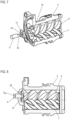
- Fig. 1 shows a screw pump 1 according to the invention, comprising an outer housing 2 with an axially arranged inlet connection 3 and a radially arranged outlet connection 4.
- a spindle housing 5 Arranged in the outer housing 2, which can also be referred to as the pump housing, is a spindle housing 5, in which, in the illustrated embodiment, three spindles—namely, a central drive spindle 6 and two idler spindles 7 arranged on either side of the drive spindle 6—are received in corresponding, intersecting spindle bores.
- the spindles 6, 7 each have spindle profiles that mesh with one another.
- a drive motor 8 is provided, which is only shown in principle here and can be a dry or wet running drive motor.
- This has a drive shaft 9, shown here only stylized, which is connected to the drive spindle 6 in a rotationally fixed manner via a coupling element 10.
- a rotation of the drive spindle 6 inevitably leads to a rotation of the two running spindles 7 due to the spindle profile engagement.
- the intermeshing spindle profiles and the spindle rotation Corresponding delivery volumes are moved or displaced axially, whereby the fluid is conveyed in a conventional manner. The fluid is sucked in axially via the inlet nozzle 3, conveyed along the spindle assembly, and exits at the motor-side end of the spindle assembly, from where it flows to the outlet nozzle 4 via a corresponding flow geometry.
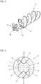
- Fig. 2 shows in the form of an exploded view the drive spindle 6 and the coupling element 10 in an enlarged, perspective view.
- the drive spindle 6, made of metal or plastic, has a spindle core 11 with a cylindrical cross-section, around which two spindle profiles 12 run, so that corresponding profile valleys 13 are formed.
- the drive spindle 6 has a recess 14, which is axially delimited by a flat bottom surface 15 and which is laterally delimited by two projections 16, wherein these two projections 16 are formed as an extension of the spindle profiles 12 running into the bottom surface 15.
- the projections 16 are machined to remove material, which will be discussed below in connection with Fig.
- the coupling element 10 also made of metal or plastic, is disc-shaped, thus having a defined maximum thickness. It comprises a cylindrical base section 17, which has two opposing, rounded element regions 18. Furthermore, in the example shown, four laterally projecting element projections 19 are provided on the base section 17, each defining a V-shaped receptacle 20 between them, into which the projections 16 engage in the assembled position, when the coupling element 10 is inserted into the recess 14.
- the bottom surface 15 is formed and bordered at least in sections by the cylindrical spindle core 11. This rounded border, resulting from the cylindrical shape of the spindle core 11, is present at the mouth of the respective profile valley 13, since the profile valley is defined by the spindle core 11.
- the spindle core 11 has a core diameter D K , which in Fig. 3 is shown.
- the coupling element 10 also has a disc-shaped, cylindrical base section 17, which has a base section diameter D B , which in Fig. 3 is also shown.
- the design of the size or geometry of the coupling element 10 is now selected such that the diameter of the base section 17 is less than or equal to the diameter of the spindle core; consequently, D B ⁇ D K applies.
- D B ⁇ D K applies.
- Fig. 4 shows a plan view of the end face of the drive spindle 6 with a view of the recess 14. Shown are the two profile valleys 13 opening there, as well as the spindle core, which defines the rounded edge of the base surface 15 in the opposite edge sections 21.
- the end face is mechanically machined using corresponding cross-grinding, which, on the one hand, results in an enlargement of the base surface 15 over the spindle core surface. On the other hand, this results in a specific form-fitting or engagement geometry of the projections 16, which have two V-shaped contact surfaces 22, with which they lie flat against corresponding contact surfaces of the coupling element 10 or are positioned closely spaced from them by a narrow gap.
- the coupling element 10 is shown in dashed lines.
- the coupling element 10 is now inserted into this recess 14, the Figures 5 and 6 show appropriate supervision ( Fig. 5 ) and a perspective view ( Fig. 6 ). Since the base section diameter D B corresponds at most to the core diameter D K , the rounded sections 18 of the coupling element 10 do not protrude into the flow cross-section defined by the spindle core 11, as the Figures 5 and 6
- the element projections 19 each define two V-shaped, laterally open receptacles 20, which are defined by two contact surfaces 23.
- the receptacles 20 extend into the base section 17, ending shortly before a plug-in receptacle 24, which is square or rectangular in cross-section and serves to receive a correspondingly shaped engagement pin of the drive shaft 9.
- the receptacles 20 accommodate the two projections 16 in a quasi-positive or form-fitting manner. Due to the contact of the surfaces 22, 23 and the respective V-shaped engagement, a rotationally fixed connection is ensured both during clockwise and counterclockwise rotation.
- the element projections 19 extend as described from the base section 17, so that here too a quasi X-shape is created, corresponding to the X-like shape of the recess or the bottom surface 15.
- the element projections 19 also ultimately do not protrude into the mouth cross-section of the respective profile valley 13 on the front surface, so that consequently the coupling element 10 represents no or almost no flow obstacle for the fluid flow. Only the Fig. 5
- the element projection 19 shown top right and bottom left protrudes slightly into the flow cross-section, but its obstacle function is negligible.
- the element projections 19 taper towards their free end and also decrease in thickness towards their free end.
- Appropriate bevels or chamfers are designed on both sides, so that even upside down installation is possible without any problems.
- Fig. 5 As shown, the coupling element 10 lies, axially seen, almost completely on the base surface 15 or covers it axially. Only the Fig. 5 Element projection 19 shown top right and the one in Fig. 5 The element projection 19 shown at bottom left extends slightly radially beyond the base surface 15 into the flow cross-section. However, this interference or cross-sectional overlap is small, so that the flow-hindering effect is almost negligible.
- FIG. 7 An exploded view of the inner housing 5 shows a screw pump with only two spindles, namely a drive spindle 6 and only one idler spindle 7, compared to the 3-spindle embodiment according to the previous figures. This serves to illustrate that a coupling according to the invention can be provided in both a 3-spindle and a 2-spindle screw pump 1.
- Fig. 8 further shows the diameter of the drive shaft 9, in Fig. 8 marked with D A , smaller than the core diameter D K of the spindle core 11.
- the diameter D A corresponds essentially to the diameter of the base section D B of the coupling element 10. This is clearly shown in Fig. 8 shown.
- the fluid exiting axially from the spindle assembly is ultimately exposed to almost no flow obstruction at all, apart from the two short element projections 19, which only slightly extend into the flow cross-section, as described above. Otherwise, the fluid can flow completely free of flow, unlike in previously known coupling devices, as described in the introduction.
- Such a screw pump can be used to pump a wide variety of fluids. It is preferably used in the automotive sector, where it serves either as a fuel pump or as a feed pump for another operating fluid, in particular for a coolant used to cool an energy storage device in the motor vehicle.
- the energy storage device is a large-volume traction storage device in an electric vehicle. It is therefore a coolant pump.
- Other applications are of course equally conceivable, for example as a feed pump for a washing fluid used for wiping the vehicle's windshield or similar.
Landscapes
- Engineering & Computer Science (AREA)
- Mechanical Engineering (AREA)
- General Engineering & Computer Science (AREA)
- Structures Of Non-Positive Displacement Pumps (AREA)
- Rotary Pumps (AREA)
- Details And Applications Of Rotary Liquid Pumps (AREA)
Description
- Die Erfindung betrifft eine Schraubenspindelpumpe, umfassend ein Spindelgehäuse, in dem eine Antriebsspindel und wenigstens eine mit dieser kämmende Laufspindel in Spindelbohrungen aufgenommen sind.
- Eine solche Schraubenspindelpumpe dient zum Fördern eines Fluids, beispielsweise von Kraftstoff oder einer Versorgungs- oder Kühlflüssigkeit oder dergleichen. Die Förderung erfolgt über wenigstens zwei miteinander kämmende Spindeln, nämlich eine Antriebsspindel, die mit einem Antriebsmotor gekoppelt ist, und eine Laufspindel, die in einem Spindelgehäuse aufgenommen sind. Das Spindelgehäuse weist hierzu der Spindelanzahl entsprechende, einander schneidende Spindelbohrungen auf. Zumeist ist das Spindelgehäuse in einem Pumpen- oder Außengehäuse aufgenommen, über das die Zu- und Abfuhr des zu fördernden Fluids erfolgt.
- Das Funktionsprinzip beruht darauf, dass die Antriebs- und die Laufspindel miteinander kämmen und aufgrund der Spindelrotation ein Fördervolumen axial verschoben wird. Die Antriebsspindel weist hierzu einen zylindrischen Spindelkern und zumeist zwei um den Spindelkern umlaufende Spindelprofile auf. Über diese Spindelprofile werden zwei umlaufende Profiltäler ausgebildet, in die entsprechende Spindelprofile der Laufspindel eingreifen. Neben einer solchen zweispindeligen Ausgestaltung ist es auch denkbar, die Schraubenspindel mit drei Spindeln auszulegen, das heißt, dass dann zwei Laufspindeln vorgesehen sind, die um 180° versetzt neben der mittigen Antriebsspindel angeordnet sind und mit dieser kämmen.
- Wie beschrieben, ist die Antriebsspindel mit einem Antriebsmotor zu koppeln, da die Antriebsspindel aktiv rotiert wird, während die eine oder die beiden Laufspindeln nur mitgenommen werden. Um die Antriebsspindel mit dem Antriebsmotor bzw. dessen Antriebswelle zu koppeln, wird stirnseitig an der Antriebsspindel ein Kupplungselement angeordnet, das mit einer entsprechenden Formschlussgeometrie drehfest mit der Antriebsspindel verbunden ist. Über diese Formschlussverbindung ist zumindest eine drehfeste Verbindung in einer Drehrichtung gegeben. Je nach Auslegung kann auch eine drehfeste Verbindung in die andere Drehrichtung gegeben sein, sodass ein Umschalten der Antriebsrichtung und damit auch der Spindeldrehrichtung möglich ist.
- Eine solche Schraubenspindelpumpe ist beispielsweise aus
DE 43 08 755 A1 bekannt. Dort ist eine Klauenkupplung beschrieben, die die Antriebswelle des Motors mit der Antriebsspindel koppelt. An einem axialen Ende der Antriebsspindel sind zwei sich kreuzende Nuten eingeschliffen, wodurch zwei einander gegenüberliegende, im Querschnitt dreieckförmige Klauen ausgebildet sind. Das scheibenförmige Kupplungselement weist einen kreisförmigen Querschnitt auf und ist mit zwei ebenfalls dreieckförmigen Ausnehmungen versehen, in die die dreieckigen Klauen der Antriebsspindel eingreifen. Mittig ist am Kupplungselement ein Schlitz vorgesehen, in den der Endabschnitt der motorseitigen Antriebswelle eingreift. - Aus
DE 10 2015 101 443 A1 ist eine Schraubenspindelpumpe bekannt, bei der das Spindelende, an dem das Kupplungselement anzuordnen ist, eben flächig ausgeführt ist. Auch die Spindelprofile enden an dieser Stirnfläche. An zwei gegenüberliegenden Positionen sind, radial gesehen, rechtwinklig aufeinander stehende Anlageflächen durch einen Materialabtrag ausgebildet. Das Kupplungselement weist eine entsprechende, dreidimensionale Aufnahme- und Eingriffsgeometrie auf, die so ausgebildet ist, dass axiale Eingriffsabschnitte vorgesehen sind, die quasi in die beiden mündenden Profiltäler eingreifen und an den in deren Bereich ausgebildeten Anlageflächen anliegen, sodass, in Umfangsrichtung gesehen, eine flächige, eine drehfeste Verbindung erwirkende Anlage des Kupplungselements an der Antriebsspindel gegeben ist, während gleichzeitig das Kupplungselement axial auf der ebenen Stirnfläche aufsitzt. - Das Dokument
DE 10 2020 108 038 offenbart ein Kupplungselement für eine Schraubenspindel, welche an ihrem Umfang Aussparungen aufweist, welche in Wirkverbindung mit axial vorstehenden Elementen der Schraubenspindel stehen. - Obwohl sich derartige Kupplungen, die oft auch als Klauenkupplungen bezeichnet werden, grundsätzlich bewährt haben, besteht ein Bedarf einer in Bezug auf die Kupplung verbesserten Schraubenspindelpumpe.
- Der Erfindung liegt damit das Problem zugrunde, eine Schraubenspindelpumpe mit einer verbesserten Kupplungseinrichtung anzugeben.
- Zur Lösung dieses Problems ist erfindungsgemäß eine Schraubenspindelpumpe vorgesehen, umfassend ein Spindelgehäuse, in dem eine Antriebsspindel und wenigstens eine mit dieser kämmende Laufspindel in Spindelbohrungen aufgenommen sind, wobei die Antriebsspindel einen zylindrischen Kern und wenigstens zwei um den Spindelkern umlaufende Spindelprofile aufweist und an einer Stirnseite der Antriebsspindel in einer über eine ebene Bodenfläche axial begrenzte Vertiefung, in der die beiden Profiltäler zwischen den beiden Spindelprofilen um 180° versetzt münden, ein scheibenförmiges Kupplungselement angeordnet ist, dass eine Einsteckaufnahme für eine Antriebswelle eines Antriebsmotors aufweist und das in zumindest einer Drehrichtung der Antriebsspindel über einen Formschlusseingriff mit axial abragenden, die Vertiefung seitlich begrenzenden Vorsprüngen, die in seitliche Aufnahmen des Kupplungselements eingreifen, drehfest mit der Antriebsspindel gekoppelt ist, wobei die Bodenfläche im Bereich der Mündungen der beiden Profiltäler über den Spindelkern begrenzt ist und das Kupplungselement in den an die Bereiche der Mündung angrenzenden Elementbereichen, der Form des Spindelkerns entsprechend, gerundet ausgeführt ist, wobei der Durchmesser des Kupplungselements im Bereich der gerundeten Elementabschnitte maximal dem Durchmesser der Spindelkerns entspricht oder kleiner als der Durchmesser des Spindelkerns ist.
- Die erfindungsgemäße Schraubenspindelpumpe weist eine strömungsoptimierte Kupplung respektive Verbindung zwischen der Antriebsspindel und dem Kupplungselement auf. Insbesondere die Geometrie des Kupplungselements ist dabei so gewählt, dass das Kupplungselement den Förderquerschnitt des jeweiligen Profiltals an dessen Mündung an der Spindelstirnfläche, wenn überhaupt, nur geringfügig verringert, sodass der freie Förderquerschnitt über das Kupplungselement nahezu nicht beeinträchtigt wird und demzufolge die Strömung, gesehen in axiale Richtung, hierüber nicht nennenswert beeinträchtigt wird, was zu einer Verbesserung der Förderleistung führt.
- Um dies zu realisieren, ist ein spezifisch ausgebildetes Kupplungselement vorgesehen, das scheibenförmig ausgeführt ist und zwei seitlich offene Aufnahmen aufweist, in die jeweils ein axial an der Stirnfläche der Antriebsspindel abragender Vorsprung eingreifen. Über diesen Formschlusseingriff wird eine drehfeste Verbindung in einer, bevorzugt natürlich in beide Drehrichtungen ermöglicht. Über diese axial abragenden Vorsprünge wird eine spindelstirnseitige Vertiefung definiert, die eine ebene Bodenfläche aufweist, wobei das Kupplungselement in eben diese Vertiefung eingesetzt wird. Dabei ist die Bodenfläche der Vertiefung u. a. vom Spindelkern der Antriebsspindel gebildet, da wie beschrieben an dieser Stirnfläche die beiden Profiltäler münden. Einander gegenüberliegend sind demzufolge vom Spindelkern gebildet, gerundete Berandungen vorgesehen. Das Kupplungselement ist derart ausgebildet, dass es in den an die Mündung der Profiltäler angrenzende Elementbereichen ebenfalls gerundet ausgeführt ist, also der Form des Spindelkerns entsprechend, wobei der Durchmesser des Kupplungselements im Bereich diese ebenfalls einander gegenüberliegenden gerundeten Elementabschnitte maximal dem Durchmesser des Spindelkerns entspricht oder kleiner als der Durchmesser des Spindelkerns ist. Das heißt, dass das Kupplungselement aufgrund seiner durchmessermäßigen Auslegung in Bezug auf den Spindelkerndurchmesser im Bereich dieser Elementabschnitte nicht in den freien Strömungsquerschnitt des jeweils mündenden Profiltals ragt, sodass hierüber zwangsläufig der Strömungsquerschnitt nicht reduziert und damit die Strömung nicht behindert wird. Anders als bei den aus dem Stand der Technik bekannten Schraubenspindelpumpen, bei denen die Kupplungselemente aufgrund ihrer Dimensionierung respektive Geometrie radial weit in den freien Strömungsquerschnitt hineinragen und diesen demzufolge stark reduzieren, stellt das Kupplungselement der erfindungsgemäßen Schraubenspindelpumpe kein nennenswertes Strömungshindernis mehr dar. Das geförderte Fluid kann demzufolge nahezu hindernisfrei axial am Kupplungselement vorbeiströmen, was sich auf dem Pumpbetrieb äußerst vorteilhaft auswirkt.
- In Weiterbildung der Erfindung kann vorgesehen sein, dass das Kupplungselement eine zylindrischen Basisabschnitt aufweist, von dem vier Elementvorsprünge zur Seite hin abragen, wobei zwei benachbarte Elementvorsprünge eine seitliche Aufnahme begrenzen. Diese Elementvorsprünge dienen lediglich dazu, die Formschlussgeometrie, also die Aufnahmen zu definieren bzw. zu begrenzen, in welche Aufnahmen die axialen spindelseitigen Vorsprünge eingreifen. Ihnen kommt folglich lediglich eine Mitnehmerfunktion zu, da über sie die drehfeste Kopplung in Umfangsrichtung erwirkt wird. Es ist daher möglich, auch diese Elementvorsprünge strömungsoptimiert schmal auszulegen, sodass auch sie den Strömungsquerschnitt nicht nennenswert verkleinern. Dabei kann die Stirnfläche der Antriebsspindel über zwei Kreuzschliffe derart bearbeitet sein, dass an den abragenden, die Vertiefung seitlich begrenzenden Vorsprüngen, die wie beschrieben die beiden Spindelprofile axial fortsetzen, entsprechende, definierte Eingriffsgeometrien in die entsprechend formgleich ausgelegten Aufnahmen vorgesehen sind. Hierüber wird die ebene Bodenfläche der Vertiefung, zusätzlich zu dem über den Spindelkern gebildeten Flächenabschnitt, seitlich etwas vergrößert, wobei in diesem Bereich, axial gesehen, die Elementvorsprünge diese erweiternden Bereiche überdecken.
- Zweckmäßig ist es, wenn sich am Kupplungselement die Aufnahmen bis in den Basisabschnitt erstrecken. Am Basisabschnitt ist die Einsteckaufnahme für die motorseitige Antriebsspindel vorgesehen, die beispielsweise als im Querschnitt längliche, rechteckige Einsteckaufnahme ausgeführt ist. Da letztlich dem Kupplungselement nur die Aufgabe zukommt, einerseits die drehfeste Verbindung zur motorseitigen Antriebswelle durch deren Eingriff in die Einsteckaufnahme, und andererseits die drehfeste Verbindung des Kupplungselements zur Antriebsspindel zu erwirken, kann sich demzufolge jede Aufnahme bis relativ weit in den zylindrischen Basisbereiche hinein erstrecken, was wiederum dazu führt, dass die vom Basisbereich abragenden, mitnehmerartigen Elementvorsprünge entsprechend kürzer bemessen werden können.
- Die Elementvorsprünge selbst sind zweckmäßigerweise dreieckförmig und verjüngen sich zu ihrem freien Ende hin, sind also insgesamt sehr schmal und auch relativ kurz ausgeführt.
- Dabei kann die Dicke jedes Elementvorsprungs zu seinem freien Ende hin abnehmen. Das Kupplungselement wird folglich materialmäßig möglichst weit reduziert.
- Die Einsteckaufnahme selbst weist bevorzugt eine viereckige Form auf. Dabei kann die Einsteckaufnahme eine rechteckige, also etwas längliche Form aufweisen, wobei sie sich mit ihrer längeren Achse zwischen den beiden gerundeten Elementabschnitten und mit ihrer kürzeren Achse zwischen den beiden Aufnahmen erstreckt. Diese Ausgestaltung ermöglicht eine extrem kompakte, kleinformatige Ausgestaltung des Kupplungselements. Denn durch diese Ausrichtung der rechteckigen Einsteckaufnahme ist es möglich, die beiden quasi V-förmigen Aufnahmen des Kupplungselements relativ weit in den zylindrischen Basisabschnitt zu ziehen. Sie enden kurz vor der Einsteckaufnahme, was, wie bereits beschrieben, schlussendlich dazu führt, dass die kupplungselementseitigen Elementvorsprünge kurz ausgeführt werden können.
- Das Kupplungselement selbst kann aus Kunststoff sein, also ein entsprechend in einem Spritzgussverfahren hergestelltes Kunststoffbauteil aus einem Kunststoff, der die gewünschten mechanischen und physikalischen Eigenschaften aufweist, z.B. in Bezug auf seine Härte, Temperaturfestigkeit und ähnliches. Alternativ dazu kann das Kupplungselement auch aus Metall, beispielsweise Aluminium oder Stahl sein.
- Wie beschrieben weist die Schraubenspindelpumpe regelmäßig auch einen Antriebsmotor auf bzw. wird an ihr ein solcher befestigt, der axial auf das Außengehäuse aufgesetzt ist und dessen Antriebswelle zwangsläufig axial mit der Längsachse der Antriebsspindel fluchtet. Denn die Antriebswelle greift wie beschrieben in die Einsteckaufnahme des Kupplungselements, das auch zentrisch in der Längsachse der Antriebsspindel sitzt, ein. Das Funktionsprinzip der Schraubenspindelpumpe beruht darauf, dass das Fluid axial gefördert wird, also das Spindelpaket axial verlässt und am Kupplungselement vorbeiströmt, das wie ausgeführt den Strömungsquerschnitt nicht oder vernachlässigbar aufgrund seiner erfindungsgemäßen Geometrie reduziert. Die motorseitige Antriebswelle weist üblicherweise ebenfalls einen zylindrischen Querschnitt auf, am Ende der Welle ist die entsprechende Einsteckgeometrie, also beispielsweise ein ebenfalls viereckiger respektive rechteckiger Eingriffszapfen ausgebildet. Da das geförderte Fluid axial das Spindelpaket verlässt, strömt es wie beschrieben am Kupplungselement vorbei, zwangsläufig dann aber auch an der Antriebswelle zumindest im Kupplungsbereich zum Kupplungselement. Um nun auch im Übergang vom Kupplungselement zur Antriebswelle kein Strömungshindernis zu haben, sieht eine zweckmäßige Weiterbildung der Erfindung einen Antriebsmotor vor, wobei der Durchmesser der zylindrischen Antriebswelle des Antriebsmotors maximal dem Durchmesser des zylindrischen Spindelkerns entspricht. Das heißt, dass auch hier eine Durchmesserabstimmung gegeben ist, sodass sichergestellt ist, dass der Antriebsspindelquerschnitt radial gesehen nicht in den Strömungsquerschnitt der Antriebsspindel greift und diesen quasi nachträglich am spindelseitigen Auslass reduziert. Das heißt, dass auch im Übergangsbereich des Kupplungselements zur Antriebsspindel keine Stufe respektive kein Strömungshindernis, bezogen auf den Spindelkerndurchmesser, gegeben ist, sodass ein nahezu ungehindertes axiales Ausströmen erfolgt. Dieses axiale Ausströmen erfolgt stets, unabhängig davon, ob die Schraubenspindelpumpe ein Trockenläufer ist, bei dem also das vom Spindelpaket geförderte Volumen nach dem Austritt aus dem Spindelpaket quasi direkt zu einem Pumpenauslass strömt, ohne durch den Antriebsmotor zu dessen Kühlung zu zirkulieren, oder ob die Schraubenspindelpumpe als Nassläufer ausgeführt ist, bei welchem ein Teil des geförderten Fluids in das Motorgehäuse eintritt, um dortige Bauteile zu kühlen und wieder in das Pumpen- oder Außengehäuse rezirkuliert. Der Durchmesser der Antriebswelle kann auch kleiner als der Spindelkerndurchmesser der Antriebsspindel sein, er kann auch dem Durchmesser des zylindrischen Basisabschnitts des Kupplungselements entsprechen.
- Wie beschrieben kann es sich bei der Schraubenspindelpumpe um eine 2-Spindel-Pumpe handeln, mit einer Antriebsspindel und nur einer seitlich dazu positionierten Laufspindel. Alternativ kann es sich auch um eine 3-Spindel-Pumpe handeln, mit einer mittigen Antriebsspindel sowie zwei links und rechts davon positionierten und mit ihr kämmenden Laufspindeln.
- Neben der Schraubenspindel selbst betrifft die Erfindung ferner die Verwendung einer solchen Schraubenspindelpumpe in einem Kraftfahrzeug zum Fördern einer Betriebsflüssigkeit. Bei dieser Betriebsflüssigkeit kann es sich um Kraftstoff oder ein sonstiges Fluid wie ein Kühlfluid beispielsweise zum Kühlen einer Traktions- oder Antriebsbatterie oder ein sonstiges Nutzfluid wie beispielsweise ein Scheibenreinigungsfluid oder ähnliches handeln. Auch in anderen Land- oder Luftfahrzeugen wie z.B. Flugzeugen oder Drohnen können solche Schraubenspindelpumpen eingesetzt werden, wobei die Einsatzmöglichkeiten hierauf nicht beschränkt sind.
- Insbesondere aber wird die Schraubenspindelpumpe als Kühlmittelpumpe, insbesondere zum Fördern eines der Kühlung eines Energiespeichers dienenden Kühlmittels verwendet. Es kann sich um ein beliebiges Kühlmittel handeln.
- Weitere Vorteile und Einzelheiten der vorliegenden Erfindung ergeben sich aus den im Folgenden beschriebenen Ausführungsbeispielen sowie anhand der Zeichnungen. Dabei zeigen:
- Fig. 1
- eine geschnittene Prinzipdarstellung einer erfindungsgemäßen Schraubenspindelpumpe mit einer Antriebs- und zwei Laufspindel,
- Fig. 2
- eine Explosionsansicht der Antriebsspindel und des nicht in die Vertiefung eingesetzten Kupplungselements,
- Fig. 3
- die Anordnung aus
Fig. 2 unter Darstellung der relevanten Durchmesser am Spindelkern und am Basisabschnitt, - Fig. 4
- eine Aufsicht auf die Stirnseite der Antriebsspindel mit Blick in die das Kupplungselement aufnehmende Vertiefung,
- Fig. 5
- die Anordnung aus
Fig. 4 mit eingesetztem Kupplungselement als Aufsicht, - Fig. 6
- die Anordnung aus
Fig. 5 als Perspektivansicht, - Fig. 7
- eine geschnittene Explosionsdarstellung eines Teils der Schraubenspindelpumpe mit prinzipiell dargestellter Antriebswelle des Antriebsmotors, und
- Fig. 8
- die Anordnung aus
Fig. 7 im montierten, geschnitten gezeigten Zustand. -
Fig. 1 zeigt eine erfindungsgemäße Schraubenspindelpumpe 1, umfassend ein Außengehäuse 2 mit einem Einlassstutzen 3, der axial angeordnet ist, und einem Auslassstutzen 4, der radial angeordnet ist. Im Außengehäuse 2, das auch als Pumpengehäuse bezeichnet werden kann, ist ein Spindelgehäuse 5 angeordnet, in dem im gezeigten Ausführungsbeispiel drei Spindeln, nämlich eine mittige Antriebsspindel 6 sowie zwei zu beiden Seiten der Antriebsspindel 6 angeordnete Laufspindel 7 in entsprechenden, einander schneidenden Spindelbohrungen aufgenommen sind. Die Spindeln 6, 7 weisen jeweils Spindelprofile auf, die ineinander greifen, also miteinander kämmen. - Vorgesehen ist des Weiteren ein hier nur prinzipiell gezeigten Antriebsmotor 8, bei dem es sich um einen trocken oder nass laufenden Antriebsmotor handeln kann. Dieser weist eine hier nur stilisiert gezeigte Antriebswelle 9 auf, die über ein Kupplungselement 10 drehfest mit der Antriebsspindel 6 verbunden ist. Das heißt, dass die Antriebsspindel 6 aktiv über den Antriebsmotor 8 angetrieben wird. Eine Rotation der Antriebsspindel 6 führt zwangsläufig aufgrund des Spindelprofileingriffs auch zu einer Rotation der beiden Laufspindeln 7. Über die ineinander greifenden Spindelprofile sowie die Spindelrotation werden entsprechende Fördervolumina axial bewegt respektive verschoben, worüber in an sich bekannter Weise die Fluidförderung erfolgt. Das Fluid wird über den Einlassstutzen 3 axial angesaugt, entlang des Spindelpakets gefördert und tritt am motorseitigen Ende des Spindelpakets aus, von wo aus es über eine entsprechende Strömungsgeometrie zum Auslassstutzen 4 strömt.
-
Fig. 2 zeigt in Form einer Explosionsansicht die Antriebsspindel 6 sowie das Kupplungselement 10 in einer vergrößerten, perspektivischen Ansicht. Die Antriebsspindel 6, aus Metall oder Kunststoff, weist einen im Querschnitt zylindrischen Spindelkern 11 auf, um den herum zwei Spindelprofile 12 laufen, sodass sich entsprechende Profiltäler 13 ausbilden. An einem axialen Ende weist die Antriebsspindel 6 eine Vertiefung 14 auf, die über eine ebene Bodenfläche 15 axial begrenzt ist, und die seitlich über zwei Vorsprünge 16 begrenzt ist, wobei diese beiden Vorsprünge 16 quasi in Verlängerung der in die Bodenfläche 15 einlaufenden Spindelprofile 12 ausgebildet sind. Die Vorsprünge 16 sind materialabtragend bearbeitet, worauf nachfolgend im Zusammenhang mitFig. 4 noch näher eingegangen wird, sodass sich insgesamt eine Bodenfläche 15 ergibt, die einerseits abschnittsweise von dem Spindelkern 11 gebildet wird, und andererseits aufgrund der mechanischen Bearbeitung der Vorsprünge 16 von daran anschließenden Bodenabschnitten, worauf nachfolgend näher eingegangen wird. - Das Kupplungselement 10, ebenfalls aus Metall oder Kunststoff, ist scheibenförmig ausgeführt, weist also eine definierte, maximale Dicke auf. Es umfasst einen zylindrischen Basisabschnitt 17, der zwei einander gegenüberliegende Elementbereiche 18 aufweist, die gerundet ausgeführt ist. Des Weiteren sind im gezeigten Beispiel 4 zur Seite abragende Elementvorsprünge 19 am Basisabschnitt 17 vorgesehen, die zwischen sich jeweils eine V-förmige Aufnahme 20 definieren, in die in der Montagestellung, wenn das Kupplungselement 10 in die Vertiefung 14 eingesetzt ist, die Vorsprünge 16 eingreifen.
- Wie
Fig. 2 , aber auchFig. 3 zeigt, wird die Bodenfläche 15 zumindest abschnittsweise von dem zylindrischen Spindelkern 11 gebildet und berandet. Diese gerundete, aus der Zylinderform des Spindelkerns 11 resultierende Berandung ist an der Mündung des jeweiligen Profiltals 13 gegeben, da das Profiltal über den Spindelkern 11 definiert ist. Der Spindelkern 11 weist einen Kerndurchmesser DK, der inFig. 3 dargestellt ist. - Wie beschrieben weist auch das Kupplungselement 10 einen scheibenförmigen, zylindrischen Basisabschnitt 17 auf, der einen Basisabschnittdurchmesser DB aufweist, der in
Fig. 3 ebenfalls dargestellt ist. Die Auslegung der Größe respektive Geometrie des Kupplungselements 10 ist nun derart gewählt, dass der Durchmesser des Basisabschnitts 17 kleiner oder gleich des Durchmessers des Spindelkerns ist, es gilt folglich DB ≤ DK. Das heißt, dass in der Montagestellung zwangsläufig die gerundeten Elementbereiche 18, an denen der Basisabschnittsdurchmesser DB gegeben ist, zwangsläufig nicht in den Strömungsquerschnitt oder Mündungsquerschnitt des jeweiligen Profiltals 13 ragen. Folglich ist durch das Kupplungselement 10 kein Strömungshindernis zumindest im Bereich der gerundeten Elementabschnitte 18 gegeben. -
Fig. 4 zeigt eine Aufsicht auf die Stirnfläche der Antriebsspindel 6 mit Blick auf die Vertiefung 14. Gezeigt sind die beiden dort mündenden Profiltäler 13, wie auch der Spindelkern, der die gerundete Berandung der Bodenfläche 15 in den einander gegenüberliegenden Randabschnitten 21 definiert. - Die Stirnfläche ist mechanisch über entsprechende Kreuzschliffe bearbeitet, was einerseits zu einer Vergrößerung der Bodenfläche 15 über die Spindelkernfläche führt. Andererseits ergibt sich eine spezifische Formschluss- oder Eingriffsgeometrie der Vorsprünge 16, die zwei V-förmige Anlageflächen 22 aufweisen, mit denen sie flächig an entsprechenden Anlageflächen des Kupplungselements 10 anliegen respektive eng über einen schmalen Spalt beabstandet dazu positioniert sind. Das Kupplungselement 10 ist gestrichelt dargestellt.
- Über die Ausbildung der Kreuzschliffe ergeben sich vier seitliche Vergrößerungsabschnitte der Bodenfläche 15, sodass sich quasi eine X-Form ergibt, wie
Fig. 4 anschaulich zeigt. - In diese Vertiefung 14 wird nun das Kupplungselement 10 eingesetzt, die
Figuren 5 und 6 zeigen eine entsprechende Aufsicht (Fig. 5 ) sowie eine perspektive Ansicht (Fig. 6 ). Da der Basisabschnittdurchmesser DB maximal dem Kerndurchmesser DK entspricht, ragen folglich die gerundeten Abschnitte 18 des Kupplungselements 10 nicht in den über den Spindelkern 11 definierten Strömungsquerschnitt, wie dieFiguren 5 und 6 anschaulich zeigen. Die Elementvorsprünge 19 begrenzen jeweils zwei V-förmige, seitlich offene Aufnahmen 20, die über zwei Anlageflächen 23 definiert sind. Die Aufnahmen 20 erstrecken sich bis in den Basisabschnitt 17 hinein, sie enden kurz vor einer Einsteckaufnahme 24, die vier- bzw. rechteckig im Querschnitt ist und der Aufnahme eines entsprechend geformten Eingriffszapfens der Antriebswelle 9 dient. In der Montagestellung gemäß derFiguren 5 und 6 nehmen die Aufnahmen 20 die beiden Vorsprünge 16 quasi formschlüssig respektive formangepasst auf. Aufgrund der Anlage der Flächen 22, 23 und des jeweiligen V-förmigen Eingriffs ist eine drehfeste Verbindung sowohl bei einer Rotation im als auch gegen den Uhrzeigersinn gegeben. - Die Elementvorsprünge 19 erstrecken sich wie beschrieben vom Basisabschnitt 17, sodass sich auch hier quasi eine X-Form ergibt, entsprechend der X-ähnlichen Form der Vertiefung respektive der Bodenfläche 15. Auch die Elementvorsprünge 19 ragen letztlich nicht in den Mündungsquerschnitt des jeweiligen Profiltals 13 an der Stirnfläche, sodass folglich das Kupplungselement 10 kein oder nahezu kein Strömungshindernis für den Fluidstrom darstellt. Lediglich der in
Fig. 5 rechts oben und links unten gezeigte Elementvorsprung 19 ragt geringfügig in den Strömungsquerschnitt, seine Hindernisfunktion ist jedoch vernachlässigbar. - Wie die
Figuren 5 und 6 zeigen, verjüngen sich die Elementvorsprünge 19 zu ihrem freien Ende hin, sie nehmen zu ihrem freien Ende auch in ihrer Dicke ab. Es sind entsprechende Schrägflächen oder Fasen ausgebildet, und zwar an beiden Seiten, sodass auch eine umgedrehte Montage problemlos möglich ist. - Wie
Fig. 5 zeigt, liegt, axial gesehen, das Kupplungselement 10 nahezu vollständig auf der Bodenfläche 15 auf respektive überdeckt diese axial. Lediglich der inFig. 5 rechts oben gezeigte Elementvorsprung 19 und der inFig. 5 links unten gezeigte Elementvorsprung 19 ragt etwas radial über die Bodenfläche 15 hinaus in den Strömungsquerschnitt. Dieser Eingriff oder diese Querschnittsüberdeckung ist jedoch gering, sodass der strömungshindernde Effekt nahezu vernachlässigbar ist. -
Fig. 7 zeigt eine Explosionsansicht des Innengehäuses 5 eine Schraubenspindelpumpe mit nur zwei Spindel, nämlich wiederum eine Antriebsspindel 6 sowie nur eine Laufspindel 7, verglichen mit der 3-spindeligen Ausführungsform gemäß den vorstehenden Figuren. Dies dient der Darstellung, dass eine erfindungsgemäße Kupplung sowohl bei einer 3- also bei einer 2-spindeligen Schraubenspindelpumpe 1 vorgesehen werden kann. - In der Explosionsdarstellung gemäß
Fig. 7 ist am axialen Ende der Antriebsspindel 6 eine identisch ausgeführte Vertiefung 14 wie vorstehend beschrieben ausgebildet, ein identisches Kupplungselement 10 wird in diese Vertiefung 14 eingesetzt. Dargestellt ist des Weiteren prinzipiell die Antriebswelle 9 des Antriebsmotors mit dem endseitigen Einsteckzapfen 25, der formschlüssig in die Einsteckaufnahme 24 greift. In der Montagestellung, wie sie inFig. 8 gezeigt ist, greift der Einsteckzapfen 25 in die Einsteckaufnahme 24, während gleichzeitig das Kupplungselement 10 in die Vertiefung 14 gesetzt ist. Eine Rotation der Antriebswelle 9 führt daher zwangsläufig, über das Kupplungselement 10 gekoppelt, zu einer Rotation der Antriebswelle 6 und über diese auch der Laufspindel 7, sodass die Pumpe das Fluid fördern kann. Aufgrund der Geometrie der Vorsprünge 16 sowie der Aufnahmen 20 und der jeweiligen V-förmigen Ausgestaltung über die entsprechenden Anlageflächen ist eine Drehung der Antriebswelle 9 und damit der Antriebsspindel 6 sowohl im Uhrzeigersinn, also in Förderrichtung, also auch bei Bedarf gegen den Uhrzeigersinn möglich, da in beiden Drehrichtungen eine drehfeste Kopplung gegeben ist. - Wie
Fig. 8 ferner zeigt, ist der Durchmesser der Antriebswelle 9, inFig. 8 mit DA gekennzeichnet, kleiner als der Kerndurchmesser DK des Spindelkerns 11. Der Durchmesser DA entspricht im Wesentlichen dem Durchmesser des Basisabschnitts DB des Kupplungselements 10. Dies ist anschaulich inFig. 8 gezeigt. Hieraus resultiert, dass folglich im Übergang des Kupplungselements 10 zur Antriebswelle 9 ebenfalls keine ein Strömungshindernis darstellende Stufe ausgebildet ist, was der Fall wäre, wenn der Durchmesser DA größer als der Basisabschnittsdurchmesser DB wäre. Das heißt, dass das axial aus dem Spindelpaket austretende Fluid letztlich nahezu überhaupt keinem Strömungshindernis ausgesetzt ist, abgesehen von den beiden kurzen, nur geringfügig in den Strömungsquerschnitt tragenden Elementvorsprüngen 19, wie vorstehend beschrieben. Ansonsten kann das Fluid vollständig strömungsfrei fließen, anders als bei bisher bekannten Kupplungseinrichtungen, wie einleitend beschrieben. - Eine solche Schraubenspindelpumpe 1, egal ob es sich um eine zwei Spinden oder eine drei Spindeln aufweisende Pumpe handelt, kann zur Förderung unterschiedlichster Fluide verwendet werden. Bevorzugt kommt sie im Kraftfahrzeugbereich zum Einsatz und dort entweder als Kraftstoffpumpe oder als Förderpumpe für ein sonstiges Betriebsfluid, insbesondere für ein Kühlmittel, das zum Kühlen eines Energiespeichers des Kraftfahrzeugs verwendet wird. Bei dem Energiespeicher handelt es sich um einen großvolumigen Traktionsspeicher eines Elektrofahrzeugs. Es handelt sich also um eine Kühlmittelpumpe. Andere Einsatzzwecke sind natürlich gleichermaßen denkbar, beispielsweise als Förderpumpe für ein Waschfluid, das zum Scheibenwischen des Fahrzeugs verwendet wird oder ähnliches.
Claims (12)
- Schraubenspindelpumpe, umfassend ein Spindelgehäuse (5), in dem eine Antriebsspindel (6) und wenigstens eine mit dieser kämmende Laufspindel (7) in Spindelbohrungen aufgenommen sind, wobei die Antriebsspindel (6) einen zylindrischen Spindelkern (11) und wenigstens zwei um den Spindelkern (11) umlaufende Spindelprofile (12) aufweist und an einer Stirnseite der Antriebsspindel (6) in einer über eine ebene Bodenfläche (15) axial begrenzte Vertiefung (14), in der die beiden Profiltäler (13) zwischen den beiden Spindelprofilen (12) um 180° versetzt münden, ein scheibenförmiges Kupplungselement (10) angeordnet ist, das eine Einsteckaufnahme (24) für eine Antriebswelle (9) eines Antriebsmotors (8) aufweist und das in zumindest einer Drehrichtung der Antriebsspindel (6) über einen Formschlusseingriff mit axial abragenden, die Vertiefung (14) seitlich begrenzenden Vorsprüngen (16), die in seitliche Aufnahmen (20) des Kupplungselements (10) eingreifen, drehfest mit der Antriebsspindel (6) gekoppelt ist, wobei die Bodenfläche (15) im Bereich der Mündungen der beiden Profiltäler (13) über den Spindelkern (11) begrenzt ist, dadurch gekennzeichnet, das Kupplungselement (10) in den an die Bereiche der Mündung angrenzenden Elementbereichen (18), der Form des Spindelkerns (11) entsprechend, gerundet ausgeführt ist, wobei der Durchmesser (DB) des Kupplungselements (10) im Bereich der gerundeten Elementbereiche (18) maximal dem Durchmesser (DK) des Spindelkerns (11) entspricht oder kleiner als der Durchmesser (DK) des Spindelkerns (11) ist.
- Schraubenspindelpumpe nach Anspruch 1, dadurch gekennzeichnet, dass das Kupplungselement (10) einen zylindrischen Basisabschnitt (17) aufweist, von dem vier Elementvorsprünge (19) abragen, wobei zwei benachbarte Elementvorsprünge (19) eine seitliche Aufnahme (20) begrenzen.
- Schraubenspindelpumpe nach Anspruch 2, dadurch gekennzeichnet, dass sich die Aufnahme (20) bis in den Basisabschnitt (17) erstreckt.
- Schraubenspindelpumpe nach Anspruch 2 oder 3, dadurch gekennzeichnet, dass die Elementvorsprünge (19) dreieckförmig sind und sich zu ihrem freien Ende hin verjüngen.
- Schraubenspindelpumpe nach einem der Ansprüche 2 bis 4, dadurch gekennzeichnet, dass die Dicke jedes Elementvorsprungs (19) zu seinem freien Ende hin abnimmt.
- Schraubenspindelpumpe nach einem der Ansprüche 2 bis 5, dadurch gekennzeichnet, dass die Einsteckaufnahme (24) eine viereckige Form aufweist.
- Schraubenspindelpumpe nach Anspruch 6, dadurch gekennzeichnet, dass die Einsteckaufnahme (24) eine rechteckige Form aufweist, wobei sie sich mit ihrer längeren Achse zwischen den beiden gerundeten Elementabschnitten (18) und mit ihrer kürzeren Achse zwischen den beiden Aufnahmen (20) erstreckt.
- Schraubenspindelpumpe nach einem der vorangehenden Ansprüche, dadurch gekennzeichnet, dass das Kupplungselement (10) aus Kunststoff oder Metall ist.
- Schraubenspindelpumpe nach einem der vorangehenden Ansprüche, gekennzeichnet durch einen Antriebsmotor (8), wobei der Durchmesser DA) der zylindrischen Antriebswelle (9) des Antriebsmotors (8) maximal dem Durchmesser (DK) des zylindrischen Spindelkerns (11) entspricht.
- Schraubenspindelpumpe nach einem der vorangehenden Ansprüche, dadurch gekennzeichnet, dass eine mittige Antriebsspindel (6) und zwei beidseits davon angeordnete Laufspindeln (7) vorgesehen sind.
- Verwendung einer Schraubenspindelpumpe (1) nach einem der vorangehenden Ansprüche in einem Kraftfahrzeug zum Fördern einer Betriebsflüssigkeit.
- Verwendung nach Anspruch 11, dadurch gekennzeichnet, dass die Schraubenspindelpumpe (1) als Kühlmittelpumpe, insbesondere zum Fördern eines der Kühlung eines Energiespeichers dienenden Kühlmittels verwendet wird.
Applications Claiming Priority (1)
| Application Number | Priority Date | Filing Date | Title |
|---|---|---|---|
| DE102021133099.8A DE102021133099A1 (de) | 2021-12-14 | 2021-12-14 | Schraubenspindelpumpe |
Publications (2)
| Publication Number | Publication Date |
|---|---|
| EP4198310A1 EP4198310A1 (de) | 2023-06-21 |
| EP4198310B1 true EP4198310B1 (de) | 2025-06-04 |
Family
ID=84363936
Family Applications (1)
| Application Number | Title | Priority Date | Filing Date |
|---|---|---|---|
| EP22209989.7A Active EP4198310B1 (de) | 2021-12-14 | 2022-11-28 | Schraubenspindelpumpe |
Country Status (7)
| Country | Link |
|---|---|
| US (1) | US11828287B2 (de) |
| EP (1) | EP4198310B1 (de) |
| JP (1) | JP7457093B2 (de) |
| KR (1) | KR102748179B1 (de) |
| CN (1) | CN116263154B (de) |
| DE (1) | DE102021133099A1 (de) |
| PL (1) | PL4198310T3 (de) |
Families Citing this family (3)
| Publication number | Priority date | Publication date | Assignee | Title |
|---|---|---|---|---|
| JP2025518912A (ja) * | 2022-06-10 | 2025-06-19 | イリノイ トゥール ワークス インコーポレイティド | スクリューポンプ及びその構成要素 |
| EP4474650B1 (de) | 2023-06-09 | 2026-03-25 | Illinois Tool Works Inc. | Schraubenpumpe und ihre komponenten |
| US12533995B2 (en) | 2023-08-31 | 2026-01-27 | Illinois Tool Works Inc. | Battery electric vehicle temperature-regulation system |
Family Cites Families (17)
| Publication number | Priority date | Publication date | Assignee | Title |
|---|---|---|---|---|
| US2466888A (en) * | 1945-10-03 | 1949-04-12 | Porter Co Inc H K | Floating spacer bearing link for parallel shafts |
| SE384069B (sv) * | 1975-05-02 | 1976-04-12 | Imo Industri Ab | Skruvpump |
| US4308755A (en) * | 1979-06-25 | 1982-01-05 | Millar Robert J | Liquid volumetric flowmeter |
| US4674338A (en) * | 1984-12-31 | 1987-06-23 | Lake Charles Instruments, Inc. | Flow volume detection device |
| US4848164A (en) * | 1988-05-27 | 1989-07-18 | Graco Inc. | Liquid flow meter |
| DE4308755A1 (de) | 1993-03-19 | 1994-09-22 | Leistritz Ag | Klauenkupplung für eine Schraubenpumpe und Verfahren zu ihrer Herstellung |
| US8821140B2 (en) * | 2010-04-29 | 2014-09-02 | Dan Paval | Gear pump |
| WO2014138519A1 (en) * | 2013-03-07 | 2014-09-12 | Ti Group Automotive Systems, L.L.C. | Coupling element for a screw pump |
| DE102015101443B3 (de) | 2015-02-02 | 2016-05-12 | Leistritz Pumpen Gmbh | Kraftstoffpumpe |
| CN108350876B (zh) * | 2016-04-29 | 2019-07-26 | 色蔻泵北美有限责任公司 | 模块化推力补偿转子组件 |
| DE102017210770B4 (de) * | 2017-06-27 | 2019-10-17 | Continental Automotive Gmbh | Schraubenspindelpumpe, Kraftstoffförderaggregat und Kraftstofffördereinheit |
| DE102017121882B3 (de) * | 2017-09-21 | 2019-01-24 | Leistritz Pumpen Gmbh | Schraubenspindelpumpe |
| DE102019103470A1 (de) * | 2019-02-12 | 2020-08-13 | Nidec Gpm Gmbh | Elektrische Schraubenspindel-Kühlmittelpumpe |
| DE102019132653A1 (de) * | 2019-12-02 | 2021-06-02 | Leistritz Pumpen Gmbh | Schraubenspindelpumpe |
| DE102020104467A1 (de) * | 2020-02-20 | 2021-08-26 | Krauss-Maffei Wegmann Gmbh & Co. Kg | Haltevorrichtung für Munitionskörper |
| DE102020108038A1 (de) | 2020-03-24 | 2021-09-30 | Nidec Gpm Gmbh | Elektrische schraubenspindelpumpe für flüssigkeiten |
| DE102020133555A1 (de) * | 2020-12-15 | 2022-06-15 | Leistritz Pumpen Gmbh | Schraubenspindelpumpe |
-
2021
- 2021-12-14 DE DE102021133099.8A patent/DE102021133099A1/de active Pending
-
2022
- 2022-11-28 PL PL22209989.7T patent/PL4198310T3/pl unknown
- 2022-11-28 EP EP22209989.7A patent/EP4198310B1/de active Active
- 2022-12-09 US US18/078,291 patent/US11828287B2/en active Active
- 2022-12-09 JP JP2022197444A patent/JP7457093B2/ja active Active
- 2022-12-12 CN CN202211590150.3A patent/CN116263154B/zh active Active
- 2022-12-13 KR KR1020220173748A patent/KR102748179B1/ko active Active
Also Published As
| Publication number | Publication date |
|---|---|
| EP4198310A1 (de) | 2023-06-21 |
| JP7457093B2 (ja) | 2024-03-27 |
| JP2023088303A (ja) | 2023-06-26 |
| PL4198310T3 (pl) | 2025-09-22 |
| CN116263154A (zh) | 2023-06-16 |
| US20230184246A1 (en) | 2023-06-15 |
| CN116263154B (zh) | 2025-08-05 |
| KR20230090269A (ko) | 2023-06-21 |
| KR102748179B1 (ko) | 2024-12-31 |
| DE102021133099A1 (de) | 2023-06-15 |
| US11828287B2 (en) | 2023-11-28 |
Similar Documents
| Publication | Publication Date | Title |
|---|---|---|
| EP4198310A1 (de) | Schraubenspindelpumpe | |
| DE102013008973B4 (de) | Vorrichtung zum Fördern von Fluiden | |
| DE3126040C2 (de) | Hydraulische Steuervorrichtung | |
| EP2916007B1 (de) | Schraubenspindelpumpe | |
| DE4029814A1 (de) | Kleine zentrifugalpumpe | |
| EP4198311B1 (de) | Schraubenspindelpumpe | |
| DE29924585U1 (de) | Vakuumpumpe | |
| EP1365906B1 (de) | Schneckenpumpe und mehrschneckenextruder mit einer solchen schneckenpumpe | |
| DE60129590T2 (de) | Magnetpumpe | |
| DE69326495T2 (de) | Kraftstoffpumpe | |
| DE1294205B (de) | Rotierende Verdraengerpumpe | |
| DE102013022329A1 (de) | Vorrichtung zum Fördern von Fluiden | |
| EP1797327B1 (de) | Drehkolbenpumpe mit einem pumpengehäuse und zwei zweiflügeligen drehkolben | |
| DE10024741B4 (de) | Seitenkanalpumpe | |
| DE102004014457B4 (de) | Kraftstoffpumpe | |
| DE60212165T2 (de) | Flanschzahnradpumpe | |
| EP1413757A2 (de) | Motorpumpenaggregat | |
| DE112014002535T5 (de) | Einachsige Exzenterschneckenpumpe | |
| EP3680450B1 (de) | Pumpenvorrichtung insbesondere für mobile verkehrsmittel | |
| DE3502839A1 (de) | Pumpe | |
| EP1311760A1 (de) | Hydraulische radialkolbenmaschine | |
| WO2018019318A1 (de) | Rotor-stator-system mit einem einlauftrichter für eine exzenterschneckenpumpe | |
| DE7630369U1 (de) | Hydraulische maschine mit axial angeordneten kolben | |
| DE10335966B3 (de) | Exzenterschneckenpumpe | |
| DE102016108108A1 (de) | Vorrichtung und verfahren zum mischen von komponenten |
Legal Events
| Date | Code | Title | Description |
|---|---|---|---|
| PUAI | Public reference made under article 153(3) epc to a published international application that has entered the european phase |
Free format text: ORIGINAL CODE: 0009012 |
|
| STAA | Information on the status of an ep patent application or granted ep patent |
Free format text: STATUS: THE APPLICATION HAS BEEN PUBLISHED |
|
| AK | Designated contracting states |
Kind code of ref document: A1 Designated state(s): AL AT BE BG CH CY CZ DE DK EE ES FI FR GB GR HR HU IE IS IT LI LT LU LV MC ME MK MT NL NO PL PT RO RS SE SI SK SM TR |
|
| P01 | Opt-out of the competence of the unified patent court (upc) registered |
Effective date: 20230921 |
|
| STAA | Information on the status of an ep patent application or granted ep patent |
Free format text: STATUS: REQUEST FOR EXAMINATION WAS MADE |
|
| 17P | Request for examination filed |
Effective date: 20231213 |
|
| RBV | Designated contracting states (corrected) |
Designated state(s): AL AT BE BG CH CY CZ DE DK EE ES FI FR GB GR HR HU IE IS IT LI LT LU LV MC ME MK MT NL NO PL PT RO RS SE SI SK SM TR |
|
| GRAP | Despatch of communication of intention to grant a patent |
Free format text: ORIGINAL CODE: EPIDOSNIGR1 |
|
| STAA | Information on the status of an ep patent application or granted ep patent |
Free format text: STATUS: GRANT OF PATENT IS INTENDED |
|
| INTG | Intention to grant announced |
Effective date: 20240926 |
|
| GRAJ | Information related to disapproval of communication of intention to grant by the applicant or resumption of examination proceedings by the epo deleted |
Free format text: ORIGINAL CODE: EPIDOSDIGR1 |
|
| STAA | Information on the status of an ep patent application or granted ep patent |
Free format text: STATUS: REQUEST FOR EXAMINATION WAS MADE |
|
| GRAP | Despatch of communication of intention to grant a patent |
Free format text: ORIGINAL CODE: EPIDOSNIGR1 |
|
| STAA | Information on the status of an ep patent application or granted ep patent |
Free format text: STATUS: GRANT OF PATENT IS INTENDED |
|
| INTC | Intention to grant announced (deleted) | ||
| RAP3 | Party data changed (applicant data changed or rights of an application transferred) |
Owner name: LEISTRITZ PUMPEN GMBH |
|
| INTG | Intention to grant announced |
Effective date: 20250218 |
|
| GRAS | Grant fee paid |
Free format text: ORIGINAL CODE: EPIDOSNIGR3 |
|
| GRAA | (expected) grant |
Free format text: ORIGINAL CODE: 0009210 |
|
| STAA | Information on the status of an ep patent application or granted ep patent |
Free format text: STATUS: THE PATENT HAS BEEN GRANTED |
|
| AK | Designated contracting states |
Kind code of ref document: B1 Designated state(s): AL AT BE BG CH CY CZ DE DK EE ES FI FR GB GR HR HU IE IS IT LI LT LU LV MC ME MK MT NL NO PL PT RO RS SE SI SK SM TR |
|
| REG | Reference to a national code |
Ref country code: GB Ref legal event code: FG4D Free format text: NOT ENGLISH |
|
| REG | Reference to a national code |
Ref country code: CH Ref legal event code: EP |
|
| REG | Reference to a national code |
Ref country code: DE Ref legal event code: R096 Ref document number: 502022004148 Country of ref document: DE |
|
| REG | Reference to a national code |
Ref country code: IE Ref legal event code: FG4D Free format text: LANGUAGE OF EP DOCUMENT: GERMAN |
|
| REG | Reference to a national code |
Ref country code: NL Ref legal event code: MP Effective date: 20250604 |
|
| PG25 | Lapsed in a contracting state [announced via postgrant information from national office to epo] |
Ref country code: FI Free format text: LAPSE BECAUSE OF FAILURE TO SUBMIT A TRANSLATION OF THE DESCRIPTION OR TO PAY THE FEE WITHIN THE PRESCRIBED TIME-LIMIT Effective date: 20250604 Ref country code: ES Free format text: LAPSE BECAUSE OF FAILURE TO SUBMIT A TRANSLATION OF THE DESCRIPTION OR TO PAY THE FEE WITHIN THE PRESCRIBED TIME-LIMIT Effective date: 20250604 |
|
| REG | Reference to a national code |
Ref country code: LT Ref legal event code: MG9D |
|
| PG25 | Lapsed in a contracting state [announced via postgrant information from national office to epo] |
Ref country code: GR Free format text: LAPSE BECAUSE OF FAILURE TO SUBMIT A TRANSLATION OF THE DESCRIPTION OR TO PAY THE FEE WITHIN THE PRESCRIBED TIME-LIMIT Effective date: 20250905 Ref country code: NO Free format text: LAPSE BECAUSE OF FAILURE TO SUBMIT A TRANSLATION OF THE DESCRIPTION OR TO PAY THE FEE WITHIN THE PRESCRIBED TIME-LIMIT Effective date: 20250904 |
|
| PG25 | Lapsed in a contracting state [announced via postgrant information from national office to epo] |
Ref country code: BG Free format text: LAPSE BECAUSE OF FAILURE TO SUBMIT A TRANSLATION OF THE DESCRIPTION OR TO PAY THE FEE WITHIN THE PRESCRIBED TIME-LIMIT Effective date: 20250604 |
|
| PG25 | Lapsed in a contracting state [announced via postgrant information from national office to epo] |
Ref country code: HR Free format text: LAPSE BECAUSE OF FAILURE TO SUBMIT A TRANSLATION OF THE DESCRIPTION OR TO PAY THE FEE WITHIN THE PRESCRIBED TIME-LIMIT Effective date: 20250604 |
|
| PG25 | Lapsed in a contracting state [announced via postgrant information from national office to epo] |
Ref country code: RS Free format text: LAPSE BECAUSE OF FAILURE TO SUBMIT A TRANSLATION OF THE DESCRIPTION OR TO PAY THE FEE WITHIN THE PRESCRIBED TIME-LIMIT Effective date: 20250904 |
|
| PG25 | Lapsed in a contracting state [announced via postgrant information from national office to epo] |
Ref country code: LV Free format text: LAPSE BECAUSE OF FAILURE TO SUBMIT A TRANSLATION OF THE DESCRIPTION OR TO PAY THE FEE WITHIN THE PRESCRIBED TIME-LIMIT Effective date: 20250604 |
|
| PG25 | Lapsed in a contracting state [announced via postgrant information from national office to epo] |
Ref country code: NL Free format text: LAPSE BECAUSE OF FAILURE TO SUBMIT A TRANSLATION OF THE DESCRIPTION OR TO PAY THE FEE WITHIN THE PRESCRIBED TIME-LIMIT Effective date: 20250604 |
|
| REG | Reference to a national code |
Ref country code: CH Ref legal event code: U11 Free format text: ST27 STATUS EVENT CODE: U-0-0-U10-U11 (AS PROVIDED BY THE NATIONAL OFFICE) Effective date: 20251201 |
|
| PG25 | Lapsed in a contracting state [announced via postgrant information from national office to epo] |
Ref country code: PT Free format text: LAPSE BECAUSE OF FAILURE TO SUBMIT A TRANSLATION OF THE DESCRIPTION OR TO PAY THE FEE WITHIN THE PRESCRIBED TIME-LIMIT Effective date: 20251006 |
|
| PG25 | Lapsed in a contracting state [announced via postgrant information from national office to epo] |
Ref country code: IS Free format text: LAPSE BECAUSE OF FAILURE TO SUBMIT A TRANSLATION OF THE DESCRIPTION OR TO PAY THE FEE WITHIN THE PRESCRIBED TIME-LIMIT Effective date: 20251004 |
|
| PGFP | Annual fee paid to national office [announced via postgrant information from national office to epo] |
Ref country code: DE Payment date: 20251028 Year of fee payment: 4 |
|
| PG25 | Lapsed in a contracting state [announced via postgrant information from national office to epo] |
Ref country code: SM Free format text: LAPSE BECAUSE OF FAILURE TO SUBMIT A TRANSLATION OF THE DESCRIPTION OR TO PAY THE FEE WITHIN THE PRESCRIBED TIME-LIMIT Effective date: 20250604 |
|
| PGFP | Annual fee paid to national office [announced via postgrant information from national office to epo] |
Ref country code: AT Payment date: 20260113 Year of fee payment: 4 |
|
| PGFP | Annual fee paid to national office [announced via postgrant information from national office to epo] |
Ref country code: IT Payment date: 20251201 Year of fee payment: 4 |
|
| PGFP | Annual fee paid to national office [announced via postgrant information from national office to epo] |
Ref country code: FR Payment date: 20251120 Year of fee payment: 4 |
|
| PGFP | Annual fee paid to national office [announced via postgrant information from national office to epo] |
Ref country code: CH Payment date: 20251201 Year of fee payment: 4 |
|
| PG25 | Lapsed in a contracting state [announced via postgrant information from national office to epo] |
Ref country code: CZ Free format text: LAPSE BECAUSE OF FAILURE TO SUBMIT A TRANSLATION OF THE DESCRIPTION OR TO PAY THE FEE WITHIN THE PRESCRIBED TIME-LIMIT Effective date: 20250604 |
|
| PGFP | Annual fee paid to national office [announced via postgrant information from national office to epo] |
Ref country code: PL Payment date: 20251119 Year of fee payment: 4 |
|
| PG25 | Lapsed in a contracting state [announced via postgrant information from national office to epo] |
Ref country code: EE Free format text: LAPSE BECAUSE OF FAILURE TO SUBMIT A TRANSLATION OF THE DESCRIPTION OR TO PAY THE FEE WITHIN THE PRESCRIBED TIME-LIMIT Effective date: 20250604 |
|
| PG25 | Lapsed in a contracting state [announced via postgrant information from national office to epo] |
Ref country code: SK Free format text: LAPSE BECAUSE OF FAILURE TO SUBMIT A TRANSLATION OF THE DESCRIPTION OR TO PAY THE FEE WITHIN THE PRESCRIBED TIME-LIMIT Effective date: 20250604 |
|
| PGFP | Annual fee paid to national office [announced via postgrant information from national office to epo] |
Ref country code: RO Payment date: 20251124 Year of fee payment: 4 |
|
| REG | Reference to a national code |
Ref country code: DE Ref legal event code: R097 Ref document number: 502022004148 Country of ref document: DE |
|
| PLBE | No opposition filed within time limit |
Free format text: ORIGINAL CODE: 0009261 |
|
| STAA | Information on the status of an ep patent application or granted ep patent |
Free format text: STATUS: NO OPPOSITION FILED WITHIN TIME LIMIT |
|
| PG25 | Lapsed in a contracting state [announced via postgrant information from national office to epo] |
Ref country code: DK Free format text: LAPSE BECAUSE OF FAILURE TO SUBMIT A TRANSLATION OF THE DESCRIPTION OR TO PAY THE FEE WITHIN THE PRESCRIBED TIME-LIMIT Effective date: 20250604 |
|
| REG | Reference to a national code |
Ref country code: CH Ref legal event code: L10 Free format text: ST27 STATUS EVENT CODE: U-0-0-L10-L00 (AS PROVIDED BY THE NATIONAL OFFICE) Effective date: 20260416 |
|
| 26N | No opposition filed |
Effective date: 20260305 |