EP4198317B1 - Procédé de détermination de la hauteur de débit et/ou de refoulement - Google Patents
Procédé de détermination de la hauteur de débit et/ou de refoulement Download PDFInfo
- Publication number
- EP4198317B1 EP4198317B1 EP22196967.8A EP22196967A EP4198317B1 EP 4198317 B1 EP4198317 B1 EP 4198317B1 EP 22196967 A EP22196967 A EP 22196967A EP 4198317 B1 EP4198317 B1 EP 4198317B1
- Authority
- EP
- European Patent Office
- Prior art keywords
- mdl
- hyd
- signal
- centrifugal pump
- model
- Prior art date
- Legal status (The legal status is an assumption and is not a legal conclusion. Google has not performed a legal analysis and makes no representation as to the accuracy of the status listed.)
- Active
Links
Images




Classifications
-
- F—MECHANICAL ENGINEERING; LIGHTING; HEATING; WEAPONS; BLASTING
- F04—POSITIVE - DISPLACEMENT MACHINES FOR LIQUIDS; PUMPS FOR LIQUIDS OR ELASTIC FLUIDS
- F04D—NON-POSITIVE-DISPLACEMENT PUMPS
- F04D27/00—Control, e.g. regulation, of pumps, pumping installations or pumping systems specially adapted for elastic fluids
- F04D27/001—Testing thereof; Determination or simulation of flow characteristics; Stall or surge detection, e.g. condition monitoring
-
- F—MECHANICAL ENGINEERING; LIGHTING; HEATING; WEAPONS; BLASTING
- F04—POSITIVE - DISPLACEMENT MACHINES FOR LIQUIDS; PUMPS FOR LIQUIDS OR ELASTIC FLUIDS
- F04D—NON-POSITIVE-DISPLACEMENT PUMPS
- F04D15/00—Control, e.g. regulation, of pumps, pumping installations or systems
- F04D15/0066—Control, e.g. regulation, of pumps, pumping installations or systems by changing the speed, e.g. of the driving engine
-
- F—MECHANICAL ENGINEERING; LIGHTING; HEATING; WEAPONS; BLASTING
- F04—POSITIVE - DISPLACEMENT MACHINES FOR LIQUIDS; PUMPS FOR LIQUIDS OR ELASTIC FLUIDS
- F04D—NON-POSITIVE-DISPLACEMENT PUMPS
- F04D15/00—Control, e.g. regulation, of pumps, pumping installations or systems
- F04D15/0088—Testing machines
-
- F—MECHANICAL ENGINEERING; LIGHTING; HEATING; WEAPONS; BLASTING
- F04—POSITIVE - DISPLACEMENT MACHINES FOR LIQUIDS; PUMPS FOR LIQUIDS OR ELASTIC FLUIDS
- F04D—NON-POSITIVE-DISPLACEMENT PUMPS
- F04D13/00—Pumping installations or systems
- F04D13/02—Units comprising pumps and their driving means
- F04D13/06—Units comprising pumps and their driving means the pump being electrically driven
-
- F—MECHANICAL ENGINEERING; LIGHTING; HEATING; WEAPONS; BLASTING
- F04—POSITIVE - DISPLACEMENT MACHINES FOR LIQUIDS; PUMPS FOR LIQUIDS OR ELASTIC FLUIDS
- F04D—NON-POSITIVE-DISPLACEMENT PUMPS
- F04D15/00—Control, e.g. regulation, of pumps, pumping installations or systems
-
- F—MECHANICAL ENGINEERING; LIGHTING; HEATING; WEAPONS; BLASTING
- F04—POSITIVE - DISPLACEMENT MACHINES FOR LIQUIDS; PUMPS FOR LIQUIDS OR ELASTIC FLUIDS
- F04D—NON-POSITIVE-DISPLACEMENT PUMPS
- F04D29/00—Details, component parts, or accessories
- F04D29/007—Details, component parts, or accessories especially adapted for liquid pumps
-
- G—PHYSICS
- G06—COMPUTING OR CALCULATING; COUNTING
- G06F—ELECTRIC DIGITAL DATA PROCESSING
- G06F30/00—Computer-aided design [CAD]
- G06F30/20—Design optimisation, verification or simulation
-
- F—MECHANICAL ENGINEERING; LIGHTING; HEATING; WEAPONS; BLASTING
- F05—INDEXING SCHEMES RELATING TO ENGINES OR PUMPS IN VARIOUS SUBCLASSES OF CLASSES F01-F04
- F05D—INDEXING SCHEME FOR ASPECTS RELATING TO NON-POSITIVE-DISPLACEMENT MACHINES OR ENGINES, GAS-TURBINES OR JET-PROPULSION PLANTS
- F05D2260/00—Function
- F05D2260/81—Modelling or simulation
-
- F—MECHANICAL ENGINEERING; LIGHTING; HEATING; WEAPONS; BLASTING
- F05—INDEXING SCHEMES RELATING TO ENGINES OR PUMPS IN VARIOUS SUBCLASSES OF CLASSES F01-F04
- F05D—INDEXING SCHEME FOR ASPECTS RELATING TO NON-POSITIVE-DISPLACEMENT MACHINES OR ENGINES, GAS-TURBINES OR JET-PROPULSION PLANTS
- F05D2260/00—Function
- F05D2260/82—Forecasts
Definitions
- the invention relates to a method for determining the delivery flow and/or the delivery height of a speed-controlled centrifugal pump unit arranged in a hydraulic pipeline network from a system response of the pipeline network that can be detected in the centrifugal pump unit to a periodic modulation of the speed and/or the torque of the centrifugal pump unit.
- the invention further relates to a centrifugal pump unit comprising a centrifugal pump, an electric motor driving it and control electronics for controlling and / or regulating the electric motor, which is set up to carry out the method.
- the object of the present invention is to improve the method known in the prior art, in particular to reduce the noise in the useful signal despite a comparatively low excitation amplitude and at the same time to increase the accuracy of determining the delivery flow.
- centrifugal pump unit with a centrifugal pump, an electric motor driving it and control electronics for controlling and / or regulating the electric motor is proposed, the control electronics being set up to carry out the method according to the invention.
- the aforementioned method has numerous advantages. On the one hand, it improves the accuracy of the flow and/or delivery height determination, since disruptive influences on the system formed by the centrifugal pump unit and the connected hydraulic pipeline network are counteracted and the noise in the determined delivery flow and/or delivery height signal is thereby reduced. The signal therefore needs to be filtered less strongly, so that the centrifugal pump unit can react more quickly to system status changes or disruptions in the hydraulic pipeline network. Furthermore, with the periodic excitation signal, a lower excitation amplitude than in the prior art can be used and noise can thus be reduced.
- the pump-motor model is dynamic due to the repeated adjustment of the model parameter(s). This allows, among other things, to detect signs of aging on the centrifugal pump unit and to compensate for any resulting errors in the pump-motor model that increase over time. In this way, the accuracy of the delivery flow and/or delivery head determination is kept constantly high over the entire operating time of the pump unit.
- deposits on the impeller e.g. iron oxide
- can be detected commonly known as “claying" which means an early Information about necessary maintenance, especially of the entire system, can be given.
- the pump-motor model includes at least a first equation that enables calculation of the delivery flow and a second equation that enables calculation of the model speed.
- these two equations are repeatedly evaluated cyclically. In terms of signaling, this calculation can be done in parallel.
- the first equation can be a volume flow equation in integral form. It is preferably based on a hydraulic differential equation, which describes in particular a head or pressure balance (head and pressure are proportional) and is converted into the integral form in order to be able to calculate the flow in a simple manner.
- a hydraulic differential equation which describes in particular a head or pressure balance (head and pressure are proportional) and is converted into the integral form in order to be able to calculate the flow in a simple manner.
- the second equation can be a velocity equation in integral form. This is preferably based on a hydromechanical differential equation, which in particular describes a torque balance and is converted into the integral form in order to be able to calculate the model speed in a simple manner.
- the numerical solution of this first equation GI1 can be carried out by a discrete-time implementation using the so-called forward Euler integration, whereby the flow rate Q mdl on the left side of the equation at time k + 1 from the flow rate Q mdl on the right side of the equation is calculated at time k.
- ⁇ t is the time interval between time k+1 and time k.
- Estimated values are preferably used for the hydraulic resistance R hyd and the hydraulic inductance L hyd at the beginning of the method. By using the method according to the invention, any estimation error is compensated for.
- the value for the geodetic head H static can, for example, be specified manually by a user on the control electronics of the centrifugal pump unit if it is constant. However, it is also possible for the control electronics to set the value for the geodetic head H static itself, in particular to zero, based on information about the pipeline network or the application (heating system, cooling system) in which the centrifugal pump unit is operated. In the case of a variable geodetic altitude, idese must be measured or otherwise determined.
- the first equation (volume flow equation) can be separated into a first and second partial equation, whereby the first partial equation describes the static hydraulic pump map for calculating the delivery head and the second partial equation describes the dynamic volume flow equation Using the calculated delivery head is.
- the second partial equation can also be viewed as the main equation since it retains the integral form, whereas the first equation can be viewed as the secondary equation since it provides a term required in the main equation.
- the numerical solution of the second partial equation GI1b can also be done through a discrete-time implementation using forward Euler integration, whereby the flow rate Q mdl on the left side of the equation at time k+1 from the flow rate Q mdl on the right the equation is calculated at time k.
- ⁇ t is the time interval between time k+1 and time k.
- the two partial equations GI1a, GI1b can be evaluated one after the other.
- the second partial equation Eq1b is then evaluated based on the determined delivery head value H mdl ( k ), i.e. the new delivery flow value Q mdl ( k + 1) is determined.
- the actual speed ⁇ real can be used as the speed ⁇ in one embodiment variant, which can be fed specifically to the pump-motor model for this purpose.
- This actual speed ⁇ real can be measured or calculated by the motor control of the electric motor driving the centrifugal pump, which determines the torque in step a. sets.
- the model speed ⁇ mdl can be used as the speed ⁇ for the evaluation of the first equation GI1 or its first partial equation GI1a, which was previously calculated within the pump-motor model using the second equation or the speed equation GI2 became. This is possible because the fault controller that calculates the fault signal manages to correct any speed error very well, so that the model speed and the real speed are the same.
- the other variable must always also be determined, at least within the pump-motor model, but depending on whether the delivery flow or the delivery head or both variables should be determined within the scope of the method according to the invention, either only the delivery flow or only the delivery head or both variables from the pump Engine model is output.
- the speed equation GI2 describes in integral form a hydromechanical differential equation in the form of a torque balance, in which the deviation between the engine torque T mot and the theoretical pump torque T mdl plus a disturbance torque T D caused by modeling errors is integrated.
- the engine torque T mot is set by the engine control of the electric motor driving the centrifugal pump in order to reach the target speed, or is modulated directly, and is to this extent known from the engine control.
- the actual speed ⁇ real or the model speed ⁇ mdl can be used as the speed ⁇ .
- the second equation GI2 can also be solved numerically by a discrete-time implementation using forward Euler integration, where the speed ⁇ mdl on the left side of the equation at time k + 1 from the speed ⁇ mdl on the right side of the equation at Time k is calculated.
- ⁇ t is again the time interval between time k+1 and time k.
- the theoretical pump torque T mdl results from a model equation that is described in the second equation GI2 by the inner expression in brackets.
- the model parameters at, bt, ct are subject to series variation, ie they differ slightly from centrifugal pump unit to centrifugal pump unit due to tolerances, in particular by a few percent.
- variable v i describing the friction between the impeller and the medium and the variable v s describing the bearing friction can also be determined by factory measurement of the centrifugal pump unit and are known quantities.
- the mass inertia J can be calculated or measured from design data of the centrifugal pump unit and is therefore also available from the manufacturer. The same applies to the mass inertia I of the pumped medium in the impeller, which, however, is negligibly low, so that the term I d Q d t can be set to zero.
- the speed equation GI2 In order to simplify the calculation of the speed equation GI2, it can be separated into a first and second partial equation GI2a, GI2b, whereby the first partial equation GI2a describes the static hydromechanical pump map (torque map) for calculating the theoretical pump torque and the second partial equation GI2b describes the dynamic speed equation Using the calculated theoretical pump torque is.
- the second partial equation can be viewed as the main equation since it retains the integral form, whereas the first equation can be viewed as a secondary equation since it provides a term required in the main equation.
- the numerical solution of the second partial equation GI2b can again be done through a discrete-time implementation using forward Euler integration, where the speed ⁇ mdl on the left side of the equation at time k + 1 from the speed ⁇ mdl on the right side of the equation is calculated at time k.
- the second partial equation GI2b is then evaluated based on the determined pump torque T mdl ( k ), i.e. the new model speed ⁇ mdl ( k + 1) is determined.
- the difference between the actual speed and the model speed can be fed to a controller containing at least one integral component.
- the controller can be an I, PI or PID controller, as is generally known in control engineering.
- the fault signal can be the output signal of the controller or can be calculated from this controller output signal.
- the controller can be initialized with the value zero. If there is no deviation between the model speed and the actual speed, the fault signal remains unchanged. If the difference is greater than zero, the value of the interference signal increases; if it is less than zero, the value of the interference signal falls.
- the controller can be referred to as a "disturbance controller", which compensates for the deviation between the real pump and the pump model and adjusts the model speed to the actual speed.
- the controller output is therefore a measure of the (torque) deviation or disturbance of the model.
- the output signal of this controller can form the fault signal T D. Since this signal T D is included in a torque equation, the physical quantity of the controller output is a torque or "disturbance torque", because a controller output variable always has the dimension of the manipulated variable on which the controller acts.
- the interference signal can be formed by multiplying the output signal of said controller by the actual speed, so that this interference signal represents power.
- the interference signal P D can therefore be viewed as “interference power” in this case.
- a basic idea of the method according to the invention is therefore to adapt the at least one model parameter, or even several model parameters simultaneously, so that there is no disturbing torque T D and/or no disturbing power P D.
- the pump-motor model is continuously adjusted so that it always replicates reality and compensates for external disruptive influences on the centrifugal pump unit and any model errors.
- the pump-motor model is dynamic in this respect.
- a first fault signal T D and a second fault signal P D are determined by supplying the difference between the model speed and the actual speed to a controller containing at least one integral component, the output signal of this controller forms the first fault signal T D and the second fault signal P D then through Multiplying the output signal of this controller with the actual speed is formed.
- the second interference signal can be considered to be calculated from the first interference signal.
- two fault signals T D , P D which can be further processed separately and each offer the possibility of adapting or tracking one or more model variables of the pump-motor model.
- a correction signal T D1sin is determined from the disturbance signal T D and used to adapt a model parameter of the pump-motor model. It is also possible for two or more correction signals T D1sin , T D1cos to be determined from the interference signal T D and for each of these to be adapted a model parameter of the pump-motor model can be used. In this way, two or a number of different model parameters corresponding to the number of correction signals can be adjusted simultaneously.
- each correction signal T D1sin , T D1cos , P D1sin , P D1cos are determined from each of the interference signals T D, P D , and that each correction signal T D1sin , T D1cos , P D1sin , P D1cos is used to adapt a specific model parameter R hyd , J, L hyd , ct of the pump-motor model.
- each of the correction signals can be used to adjust one of the model parameters.
- correction signals that represent an active component ie are in phase with the excitation of the speed or torque, correct those model parameters that predominantly affect the active power.
- correction signals that represent reactive power ie that are 90° out of phase with the excitation, can only correct model parameters that predominantly influence the reactive power.
- the model parameter to be adjusted can be the hydraulic resistance R hyd of the pipeline network or the model parameter ct.
- the hydraulic resistance R hyd indicates the steepness of the characteristic curve of the pipeline system. It changes if the piping system has regulated valves, as is the case in heating or cooling systems. Tracking the hydraulic resistance R hyd in the pump-motor model is therefore particularly advantageous in order to ensure the accuracy of the delivery head and/or flow rate determination.
- the model parameter ct is subject to series variation from centrifugal pump unit to centrifugal pump unit and also changes with the age of the centrifugal pump unit, whereas the other parameters at and bt do not have a strong dependence and remain almost constant.
- step e the sine or cosine signal that is in phase with the excitation signal is used.
- the sine signal is used if the excitation signal is also a sine signal
- the cosine signal is used if the excitation signal is also a cosine signal.
- the hydraulic resistance R hyd can be adjusted depending on a first correction signal P D1sin , which is formed from the second disturbance signal P D
- the model parameter ct depending on a first correction signal T D1sin can be adjusted, which is formed from the first interference signal T D.
- the hydraulic resistance R hyd is adjusted depending on the first correction signal T D1sin formed from the first interference signal T D
- the model parameter ct is adjusted depending on the first correction signal P D1sin formed from the second interference signal P D.
- the model parameter to be adjusted can be the mass inertia J of the centrifugal pump unit or the hydraulic inductance L hyd of the pipeline network. Adjusting or tracking the inertia J of the centrifugal pump unit as a model parameter has the advantage that signs of aging on the centrifugal pump unit, such as deposits on the impeller (clogging) or bearing wear, can be recognized, as these increase the inertia. If the model parameter “inertia” is increased as part of the method, a message, in particular maintenance information, can be output on the centrifugal pump unit if a predetermined limit value is exceeded.
- Adjusting or tracking the hydraulic inductance as a model parameter has the advantage that structural changes to the piping system can be recognized, for example as a result of a fault that permanently cuts off a network section from the rest, or as a result of a conversion or expansion of the piping network.
- the knowledge of an increasing or decreasing hydraulic inductance can also be used to provide a notice on the centrifugal pump unit, for example To check the operating setting of the centrifugal pump unit and/or to directly adapt the control of the centrifugal pump unit, for example by increasing or reducing its reference speed or a set control characteristic.
- These model parameters J, L hyd influence the reactive power. Therefore, in this case it is provided that in step e.
- the sine or cosine signal that is 90° out of phase with the excitation signal is used.
- the cosine signal is used when the excitation signal is a sine signal
- the sine signal is used when the excitation signal is a cosine signal.
- the inertia J can be adjusted depending on a second correction signal P D1cos , which is formed from the second disturbance signal P D
- the hydraulic impedance L hyd depending on a second correction signal T D1cos can be adjusted, which is formed from the first interference signal T D.
- the inertia J is adjusted depending on the second correction signal T D1cos formed from the first interference signal T D
- the hydraulic impedance L hyd is adjusted depending on the second correction signal P D1cos formed from the second interference signal P D.
- the determination of the correction signal is preferably carried out by using a sine or cosine signal with one times the excitation frequency.
- the excitation signal has the frequency ⁇ t
- the sine or cosine signal which is multiplied with the interference signal, or in the case of two interference signals with the respective interference signal, also has this simple frequency ⁇ t, hereinafter also referred to as the fundamental frequency .
- a sine or cosine signal with double, triple or another nth multiple of the basic frequency, i.e. with a frequency 2 ⁇ t, 3 ⁇ t or n ⁇ t.
- the use of a sine or cosine signal with one times the excitation frequency i.e. the fundamental frequency
- two model parameters can already be adjusted per disturbance signal (one model parameter when using a sine signal with fundamental frequency and one when using a cosine signal with fundamental frequency in step e.), i.e. four model parameters with two disturbance signals (disturb torque and disturbance power). If twice the basic frequency is also used, two, or even four, additional model parameters can be adjusted if there are two interference signals.
- the calculation of the least one or more correction signals is a type of Fourier analysis, in which integrals are only calculated for a few individual frequencies. These integrals can be viewed as Fourier integrals.
- the adaptation of the corresponding model parameter R hyd , J, L hyd , c t is preferably carried out using a controller containing at least one integral component, to which the respective correction signal T D1sin , T D1cos , P D1sin , P D1cos is supplied, wherein the controller output signal is multiplied by an initial value for the corresponding model parameter (R hyd , J, L hyd , ct) to obtain the adjusted model parameter R hyd , J, L hyd , ct.
- the initial value can be a value measured at the factory (with inertia J or ct) or one for the intended operation of the centrifugal pump unit be the assumed mean value (at R hyd , L hyd ).
- the controller can be an I, PI or PID controller. Due to the integral component (I component) in the controller, it acts like an integrator.
- the controller output signal can be understood as a correction factor K for the model parameter.
- the controller can therefore be referred to as a “parameter controller”.
- the advantage of this arrangement is that the controller can be easily limited.
- the correction factor can be limited to a factor of 5, with permissible values preferably being between 1/5 and 5. This makes it possible to determine how far the value has moved away from the initial assumption, i.e. the initial value.
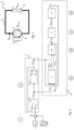
- FIG 1 shows a purely schematic representation of a centrifugal pump unit 3, 4 within a closed hydraulic system 1, in which the centrifugal pump unit 3, 4 circulates a liquid.
- the hydraulic system 1 can be, for example, a heating system or a cooling system for buildings, with system components such as heat source or chiller, heat exchanger, hydraulic switch, valves, etc. being omitted for reasons of simplicity.
- the hydraulic system 1 includes a pipeline network 2, which is different from the centrifugal pump unit 3, 4 extends to a number of consumers (flow), such as radiators, heating circuits of underfloor heating or cooling circuits of a cooling ceiling, and extends from these consumers back to the centrifugal pump unit 3, 4 (return).
- the centrifugal pump unit 3, 4 is intended to convey a heat transfer medium, such as water, to the consumers.
- Control valves such as thermostat valves or electrothermal actuators are assigned to these consumers in order to adjust the volume flow through the respective consumer or through a group of consumers. Due to the changing degree of opening of these control valves, the hydraulic load 5 to be operated by the centrifugal pump unit 3, 4 changes depending on the needs of the consumer, which in Figure 1 For the sake of simplicity, it is symbolized by a single, albeit variable, hydraulic resistance R hyd . It describes the steepness of the so-called pipe network parabola of the hydraulic system 1, also commonly called the system characteristic curve or system curve.
- the hydraulic system can also be an open system, such as in the case of a borehole pump, a wastewater lifting system or a drinking water pressure boosting system.
- the centrifugal pump unit 3, 4 includes a centrifugal pump 4 including an electric motor drive unit and pump or control electronics 4 for controlling and/or regulating the electric motor, which is also set up to carry out the method according to the invention.
- the electric motor can be, for example, a three-phase, permanently excited, electronically commutated synchronous motor.
- the control electronics 4 has a frequency converter for setting a specific speed of the electric motor.
- the centrifugal pump 4 generates a differential pressure between its suction and pressure sides, also called delivery head H real , which, depending on the hydraulic resistance R hyd of the pipeline network 2 connected to the centrifugal pump 4, leads to a delivery flow Q real .
- FIG. 2 A signal flow diagram showing the sequence of a first embodiment variant of the method according to the invention for the most precise possible computational determination the current delivery head H real and/or the current delivery flow Qreai is illustrated in Figure 2 shown.
- the process can be roughly divided into six process sections I to VI, which are explained individually below.
- the method sections I to IV essentially take place simultaneously and, as a result of their programmatic processing by software in the control electronics 4, are repeatedly executed cyclically one after the other, in particular at the clock speed of a processor, not shown, in the control electronics 4 on which the method according to the invention runs.
- the hydraulic system 1 is periodically excited.
- this is done by applying a periodic excitation signal f A (t) of a specific excitation frequency ⁇ A to a reference speed n 0 of the centrifugal pump unit 3, 4 in order to achieve a modulated target speed n should be preserved and thus the actual speed n real of the centrifugal pump 3 should be modulated, in particular allowed to fluctuate periodically.
- the periodic excitation f A (t) has the result that the differential pressure ⁇ p of the centrifugal pump 3 or its proportional delivery head H is actually modulated, which, depending on the modulation amplitude and frequency, leads to a signaling response from the hydraulic system 1, which in turn in the torque required to set the modulated target speed n target, and also in the electrical power consumption of the centrifugal pump unit, from which the delivery flow Q can be determined.
- This basic principle is in the German patent application DE 102014004336 A1 described, to which reference is hereby made.
- the reference speed n 0 can be a speed specified externally for the centrifugal pump unit 3, 4 or a speed determined internally in the control electronics 4.
- the latter can, for example, come from a characteristic curve control upstream of the speed control, for example Delivery height H is set depending on the delivery flow Q according to a defined characteristic curve in the so-called HQ diagram, or result from an automatic control that sets the delivery height H depending on other criteria, e.g. the change in flow rate dQ/dt.
- the excitation does not necessarily have to be sinusoidal.
- Another periodic signal shape such as a square, trapezoid, triangular, sawtooth or shark fin signal shape is also possible.
- the periodic excitation of the system 1 or the application of the reference speed n 0 with the excitation signal f A (t) is carried out by superposition in an adder 6, to which the reference speed n 0 and the excitation signal f A (t) are each supplied in terms of signals.
- the known engine control 7 takes place to set the modulated target speed n target , for example using a vector, in particular field-oriented, control. Since the actual speed ⁇ is actually the controlled variable in this case, it is directly available from the field-oriented control, either based on a measurement using a rotary encoder (encoder), by evaluating the voltage (back EMF) induced by the rotor magnetic field in the stator coils, or based on a calculation using a well-known algorithm for sensorless speed control.
- a rotary encoder encoder
- back EMF back EMF
- the engine control 7 includes at least one speed controller 8, to which the modulated target speed n target is supplied and which determines the torque T mot required to achieve the modulated target speed n target depending on the deviation of the actual speed ⁇ real from the target speed n target or of course ⁇ target .
- the actual speed ⁇ real is therefore also an input variable of the speed controller 8.
- the speed controller 8 can, for example, be a P, PI or PID controller, with the torque T mot being the manipulated variable. It can also be a PI-R controller that has a resonance component at the excitation frequency ⁇ A in order to achieve the lowest possible control deviation.
- the determined torque T mot is then set by the engine control 7 on the drive unit of the centrifugal pump 3, which in Figure 2 forms a physical system component.
- a corresponding (actual) speed ⁇ real of the centrifugal pump 3 results, which then generates a delivery head H real and, depending on the load 5 in the form of the hydraulic resistance R hyd, a corresponding delivery flow Q real .
- the determined actual speed ⁇ real is supplied to the speed controller 8 in order to determine the deviation from the target speed n target and to adapt the torque T mot .
- Such an engine control 7 is known per se.
- the determined torque T 0 is also fed to a mathematical pump-motor model 9, which simulates the hydromechanical behavior of the centrifugal pump 3.
- a mathematical pump-motor model 9 which simulates the hydromechanical behavior of the centrifugal pump 3.
- This pump-motor model 9 represents a so-called observer, which ideally enables observation of all state variables of the centrifugal pump 3, including non-measurable state variables.
- the pump-motor model 9 enables an estimate of the current delivery head H real , the current delivery flow Q real and the actual speed ⁇ real in the form of their respective model variables H mdl , Q mdl and ⁇ mdl , the latter also being referred to as model speed ⁇ mdl .
- FIG. 3 An embodiment variant of the pump-motor model 9 is in Figure 3 illustrated. It consists of a system of equations based on a first [GI1a, GI1b] and a second [GI2a, GI2b] differential equation, each of which is transformed into an integral form to simplify its calculation, so that they form a first and a second integral equation.
- the first integral equation [GI1a, GI1b] is based on a hydraulic differential equation that describes a pressure balance in system 1, expressed in delivery heads. It forms a volume flow equation because it enables the flow rate Q mdl to be calculated.
- the second integral equation [GI2a, GI2b] is based on a hydromechanical one Differential equation that describes a torque balance in system 1 taking friction losses into account. It forms a speed equation because it enables the model speed ⁇ mdl to be calculated.
- the two integral equations are calculated one after the other in discrete time using forward Euler integration.
- first partial equation [GI1a, GI2a] secondary equation
- second partial equation main equation
- main equation main equation
- the first partial equation [GI1a, GI2a] and then the second partial equation [GI1b, GI2b] are calculated, with the result of the solution of the respective first partial equation [GI1a, GI2a] is used, as described below using Figure 3
- the first partial equations can be viewed as secondary equations to the second partial equations, which in turn form the main equations due to their integral form.
- the pump motor model 9 in Figure 3 includes three function blocks 9.1, 9.2, 9.3.
- the main equation GI1b of the first integral equation (volume flow equation) is evaluated.
- the main equation GI2b of the second integral equation (velocity equation) is evaluated in the third function block 9.3.
- the second and third function blocks 9.2, 9.3 are preceded by the first function block 9.1, in which the two secondary equations GI1a, GI2a (pressure and torque characteristics) of the integral equations are evaluated.
- the first partial equation GI1a of the first integral equation describes the speed-dependent relationship between delivery flow Q and delivery head H, more precisely the pump performance map, i.e. for each speed ⁇ the dependence of the delivery head H on the delivery flow Q, whereby this relationship is referred to as the pump curve H ⁇ (Q). .
- the speed ⁇ is constant along such a pump curve H ⁇ (Q).
- the entirety of all pump curves H ⁇ (Q) forms the pump map H( ⁇ , Q).
- the pump map H( ⁇ , Q) is usually measured at the factory and specified in the technical documentation of a centrifugal pump unit 3.
- the model parameters a, b, c that mathematically describe the pump characteristic map H( ⁇ , Q) are therefore known.
- the speed ⁇ and the flow rate Q are required.
- the speed ⁇ is actually provided as the actual speed ⁇ by the engine control 7 or fed to the first function block 9.1.
- the calculated flow rate Q mdl from the output of the second function block 9.2 is used as the flow rate Q and is also fed to the first function block 9.1, whereby the flow rate Q mdl is zero at the beginning of the method or a defined initial value is used.
- the calculated model variable H mdl is output at the output of the first function block 9.1 and thus also forms the delivery head H mdl to be determined according to the invention, which is output at the output of the pump-motor model 9 as the first output variable.
- the calculated delivery height model variable H mdl is transferred to the second function block 9.2, in which it is used to calculate the delivery flow Q mdl using the second partial equation GI1b of the first integral equation.
- the hydraulic Resistance R hyd the hydraulic impedance L hyd , the current flow Q mdl (k) and the geodetic head H static are required.
- the geodetic head H static is the head H that must be reached at least so that a flow rate (Q>0) is possible at all.
- the geodetic head H static In closed hydraulic systems, ie those pipeline networks in which the pumped medium circulates, such as in a heating or cooling system, the geodetic head H static is zero and can be neglected in this case.
- the geodetic head H static In the case of an open system, the geodetic head H static can, for example, be measured or specified by a user on the pump electronics 4 of the centrifugal pump.
- the hydraulic resistance R hyd and the hydraulic impedance L hyd are initially unknown, since these parameters are part of the user's hydraulic system 1, which the pump manufacturer does not know.
- the hydraulic inductance L hyd, together with the volume flow, is a measure of the kinetic energy that is stored in the flowing water mass. As long as the system is not structurally modified, the hydraulic impedance L hyd does not change either. It can be used in the design variant according to Figures 2 and 3 can be determined by a simple estimate.
- the hydraulic resistance R hyd changes dynamically during operation of the system 1 depending on the needs of the consumers, in particular the heating or cooling requirements, ie depending on the position of the control valves on the consumer side, which adjust the volume flow through the consumers.
- the inductance L hyd also changes.
- the hydraulic resistance R hyd is a model parameter of the pump-motor model 9, which according to the invention is dynamic is adjusted. It is repeatedly determined by a parameter controller 12 and fed to the pump-motor model 9, more precisely to the second function block 9.2, in order to be used in partial equation GI1b. Since the hydraulic resistance R hyd is unknown at the beginning of the process, any initial value can be used for R hyd . Because in the course of the process, its value is corrected by the parameter controller 12 to the real value, as will be explained below.
- the volume flow value Q to be used in equation GI1b is the volume flow value that is valid at the current time k. Partial equation GI1b can therefore be evaluated and the new volume flow Q mdl (k+1) can be determined. It therefore represents the output signal of the second function block 9.2 and the second output variable of the pump-motor model 9.
- the first part GI2a of the second integral equation describes the speed-dependent relationship between torque T and flow rate Q. It is therefore basically a torque equation. Like partial equation GI1a, it requires the current speed ⁇ ( k ) and the current flow rate Q(k). As explained for the individual equation GI1a, the actual speed ⁇ supplied by the engine control 7 to the first function block 9.1 is real as the speed ⁇ and the current delivery flow Q(k) is the delivery flow Q mdl (k+1) from the output of the second function block, which was last calculated using partial equation GI1b 9.2 used.
- v i ⁇ 2 in partial equation GI2a describes the friction between the impeller and the medium, the term v s ⁇ bearing friction losses that result from the bearing of the pump or motor shaft. Both variables v i and v s can be determined at the factory by measuring the centrifugal pump and are known to this extent. Furthermore, the term describes I d Q d t the moment of inertia of the medium in the impeller. Due to the comparatively small amount of pumped medium in the impeller, the term I d Q d t comparatively small and can be neglected.
- the model parameters at, bt and ct describe the physical relationship between the torque T, flow rate Q and the speed ⁇ , with others Words, the torque map T( ⁇ , Q) of the centrifugal pump 3 formed from the individual torque curves T ⁇ (Q), the speed ⁇ being constant along a torque curve T ⁇ (Q). Since, as already mentioned, each pump unit is measured by the manufacturer and its hydraulic and hydromechanical pump characteristics are known to the manufacturer, the model parameters at, bt and ct are also known. In the present example, the model parameter ct is a value that can change over time. Its initial value can also be determined at the factory by measuring the centrifugal pump 3.
- the calculated model variable T mdL is also output at the output of the first function block 9.1 and transferred to the third function block 9.3, in which it is used to calculate the model speed ⁇ mdl using the second partial equation GI2b of the second integral equation.
- the moment of inertia J, the engine torque T mot and the value of a disturbance torque T D are also required, which exists in the event of a deviation of the model speed from the actual speed, ie is greater than zero.
- the moment of inertia J of the rotating components (shaft, rotor, impeller) of the centrifugal pump 3 can also be determined at the factory by measuring the centrifugal pump 3 or calculated from design data.
- the engine torque T mot is supplied to the pump-motor model 9 or the third functional block 9.3 by the engine control 7.
- the disturbance torque T D is determined by a disturbance controller 10 and also fed to the pump-motor model 9 or the third function block 9.3.
- Partial equation GI2b can thus be evaluated and the model speed ⁇ mdl can be determined. It therefore represents the output signal of the third function block 9.3 and the third output variable of the pump-motor model 9.
- the equations of the pump-motor model 9 are continuously and repeatedly calculated, in particular depending on the clock rate of the processor of the control electronics 4 on which this calculation is carried out. In each cycle, a new flow rate value Q mdl (k+1) or speed value ⁇ mdl (k+1) is calculated from the flow rate value Q mdl (k) or speed value ⁇ mdl (k) used in the previous cycle.
- the current speed of the centrifugal pump 3 is estimated as the model speed ⁇ mdl and fed to a fault controller 10, which also receives the actual speed ⁇ real of the centrifugal pump 3.
- the fault controller 10 forms a fourth method section IV, compare Figure 2 . It first determines whether and to what extent there is a real deviation of the model speed ⁇ mdl from the actual speed ⁇ , and determines a fault signal T D from this deviation. In this respect, the fault controller 10 forms a fault signal calculation unit. He is responsible for setting or regulating the model speed ⁇ mdl so that it corresponds to the real speed ⁇ real .
- a first embodiment variant of the fault controller 10 is in Figure 4 shown. It includes a subtractor 14, which calculates the deviation ( ⁇ real - ⁇ mdl ) of the model speed ⁇ mdl from the actual speed ⁇ real of the centrifugal pump unit 3, 4.
- This part of the disturbance controller 10 can be understood together with the pump-motor model 9 as a "torque observer" because a deviation of the model speed ⁇ mdl from the actual speed ⁇ real means a deviation of the model 9 from reality, which manifests itself in a disturbance torque , which in turn is responsible for the speed deviation.
- the fault controller 10 includes a controller 15 with an integral component, which is designed here as a PID controller.
- the calculated deviation or speed difference is fed to this controller 15 and integrated based on the integral component.
- the physical size of the controller output is defined by the connected manipulated variable, so that from a physical point of view the controller output signal (controller manipulated variable) corresponds to a torque.
- the controller output signal directly forms the disturbance signal T D , which can accordingly be viewed as a disturbance torque T D.
- the fault controller 10 can therefore also be referred to as a “disturbance observer”.
- the disturbance torque T D accelerates the model speed ⁇ mdl if it is lower than the actual speed ⁇ real , and brakes the model speed ⁇ mdl if it is greater than the actual speed ⁇ real .
- the interference signal T D compensates in this way Deviation of the pump-motor model 9 from reality. Such a deviation can be caused, for example, by inaccurate parameter values, but can also be due to external disturbances, such as torque fluctuations due to particles or bubbles in the pumped medium or due to changing bearing friction.
- the PID controller 15 of the fault controller 10 is initialized with the value 0. If the speeds ⁇ real and ⁇ mdl are identical, their deviation is zero and the disturbance signal T D (disturbance torque) is constant or also equal to zero at the beginning of the process. If there is a negative deviation between the speeds ⁇ mdl and ⁇ real , ie that the actual speed ⁇ real lags behind the model speed ⁇ mdl , the disturbance signal T D drops. This can be interpreted to the effect that in reality a disturbance torque (braking torque) acts, as a result of which the centrifugal pump 3 actually has a lower speed ⁇ real than the pump-motor model 9 estimates. In other words, in reality there are losses (e.g.
- the pump-motor model 9 has the model speed ⁇ mdl estimates too high. If there is a positive deviation between the speeds ⁇ mdl and ⁇ real , that is, the model speed ⁇ mdl is estimated to be smaller than the actual speed ⁇ real , the disturbance signal T D increases steadily as a result of the I component of the controller 15. A model speed ⁇ mdl that is too low can occur if the pump-motor model 9 models the centrifugal pump unit 3, 4 together with the connected system 1 with too much loss and is possibly over-adapted.
- the fault signal T D is then fed to an evaluation unit 11 and evaluated therein, which represents a fifth method section V.
- the evaluation unit 11 according to Figure 2 is set up to determine a correction signal T D1sin from the interference signal T D. This is done in such a way that the interference signal T D is first multiplied by a sine signal whose frequency corresponds to one times the excitation frequency ⁇ A , ie the fundamental frequency of the excitation signal fA(t). The product thus formed is then integrated over at least one period T of the excitation signal f A (t) in order to obtain the correction signal T D1sin . Mathematically speaking, this is a sine transformation.
- the correction signal T D1sin is then fed to a parameter controller 12, which is set up to carry out an adjustment of a model parameter depending on the correction signal T D1sin .
- the model parameter to be adjusted is in the embodiment variant Figure 2 (only) the hydraulic resistance R hyd of the pipeline network 2.
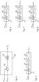
- a first embodiment variant of the parameter controller 12 is in Figure 5 shown. It includes a controller 17 with an integral component, to which the correction signal T D1sin is supplied.
- the controller 17 is implemented here as a PID controller.
- the output signal of this controller 17 represents a correction factor K.
- the controller 17 is initialized with the value 1 at the beginning of the method, so that the correction factor K initially has the value 1.
- a correction signal T D1sin is greater than zero, the correction factor K is increased as a result of the integral component of the controller 17. If the correction signal T D1sin is less than zero, the correction factor K is reduced as a result of the integration of the correction signal T D1sin .
- the model parameter R hyd is consequently dynamically adjusted, in particular "regulated", by the parameter controller 12, with the correction factor K indicating as a manipulated variable how large the deviation of the model parameter R hyd is from the initial value.
- the correction factor K thus generally makes it possible to obtain further information about the centrifugal pump unit 3, 4 or the pipeline network 2, such as information about aging/wear of the centrifugal pump 3, deposits on the impeller (clogging) or a fault in the pipeline network. This enables the condition of the centrifugal pump to be monitored 3, 4 possible. If the correction factor K exceeds or falls below a predetermined limit value, an error message, a warning and/or maintenance notice can be issued.
- the parameter controller 12 can further have a correction factor limit 18, which limits the correction factor K to an upper and/or lower limit value, for example to the upper value 5 or to the lower value 1/5, so that the permissible range of values for the to be adjusted Model parameters are a maximum of five times and one fifth of the initial value.
- the correction factor limit 18 therefore lies, in terms of signaling, between the controller 17 and the multiplier 19.
- the parameter controller 12 can have a linearization unit 20, so that the parameter controller 12 shows the same behavior when increasing as when reducing and the interference signal TD1 sin becomes proportional to the change in volume flow.
- the model parameter R hyd which may be adjusted by the parameter controller 12, is then fed to the pump-motor model 9.
- the pump-motor model 9 uses the adapted model parameter in the second function block 9.2 to calculate the delivery flow Q mdl .
- Figure 9 and 10 show a second embodiment variant of the pump-motor model 9a. It differs from the first embodiment variant in that Pump motor model 9a no actual speed ⁇ is actually supplied by the motor control 7. Instead, in the pump-motor model 9a, the model speed ⁇ mdl , which was internally calculated in the previous cycle, is used in the individual equations GI1a, GI2a, for which the output of the third function block 9.3 is traced back to the input of the first function block 9.1, see Figure 10 . This is possible because the fault controller 10 is able to correct any speed errors very well.
- Procedural section Function block function I Speed specification Periodic excitation of a reference speed II Motor control Speed control and determination of the actual speed and torque III Pump motor model Calculation/observation of speed, delivery head and flow rate IV Disturbance regulator Calculation of a disturbance signal; High bandwidth regulator, or a bandwidth of at least a decade above the excitation frequency; ensures that model speed corresponds to actual speed v Evaluation unit Calculation of one or more correction signals from the interference signal VI Parameter controller Model parameter adjustment depending on the correction signal
- This method improves the accuracy of the delivery flow and/or delivery height determination, since every disturbing moment T D is counteracted by the disturbance controller 10 and the subsequent parameter adjustment in the parameter controller 12, thereby reducing the noise in the delivery flow and/or delivery height signal compared to the procedure in the state of the technology is reduced.
- the signal quality can thus be improved or, while the quality of the excitation signal remains the same, a lower excitation amplitude can be used than in the prior art or subsequent smoothing can be reduced by filtering, so that a faster reaction of the centrifugal pump unit 3, 4 to system state changes or Disturbances in the hydraulic pipeline network 2 can occur.
- any inaccuracies in the pump-motor model 9 are also compensated for, which may be due to a scattering of the model parameters in series production and/or aging-related wear, for example of the bearings of the centrifugal pump 3.
- the hydraulic resistance R hyd needs to be tracked, at least as long as the other model parameters are known from a measurement, estimate, calculation, etc., since R hyd is the only dynamically changing parameter. Nevertheless, the hydraulic resistance R hyd could also be determined in another way and fed to the pump-motor model 9.
- the method according to the invention is therefore not limited to tracking the hydraulic resistance R hyd with the evaluation unit 11 and the parameter controller 12. Rather, a single other parameter can also be tracked, such as the moment of inertia J, the hydraulic impedance L hyd or the parameter ct.
- the parameter controller is 12 in Figure 2 or 9 through the moment of inertia controller 12' Figure 6 , in the case of the hydraulic impedance L hyd by the impedance controller 12".
- the evaluation unit 11 also outputs a different correction signal, as will be explained below.
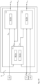
- Figure 11 shows a third embodiment variant of the method according to the invention. It differs from the first and second variants essentially in that that the evaluation unit 11a obtains the actual speed ⁇ real and calculates several correction signals, whereby each correction signal can be used to adapt an individual model parameter, so that a number of model parameters of the pump-motor model 9b corresponding to the number of correction signals can be adapted simultaneously.
- Each correction signal is calculated in a correction signal calculation unit 11.1, 11.2, all of which are part of the evaluation unit 11a.
- the evaluation unit 11a can calculate a second fault signal P D from the actual speed ⁇ real . Furthermore, the evaluation unit 11a can calculate one or more correction signals from both the first interference signal T D and this second interference signal P D.
- the evaluation unit 11a is set up to carry out a discrete sine/cosine transformation of the disturbance signal T D or disturbance torque T D at the fundamental frequency ⁇ A of the excitation signal f A (t).
- a first correction signal T D 1 sin is calculated, which represents an active component (or real part) and is in phase with the excitation signal f A (t).
- a second correction signal T D1cos is calculated, which represents a reactive component (or imaginary part) and is orthogonal to the excitation signal f A (t).
- the direct component T D 0 of the interference signal T D can be calculated as a third correction signal.
- T Dnsin 1 T ⁇ t t + T T D t ⁇ sin n ⁇ A t d t
- T Dncos 1 T ⁇ t t + T T D t ⁇ cos n ⁇ A t d t
- the evaluation unit 11a is also set up to calculate a second interference signal P D and to carry out a discrete sine/cosine transformation of this second interference signal P D at the fundamental frequency of the excitation signal f A (t).
- the fault controller 10a includes 10a, which is in Figure 12 is used, in this case additionally a multiplier 16, which actually multiplies the output signal of the controller 15, ie the disturbance torque T D , by the actual speed ⁇ and thus provides a disturbance power P D at its output.
- the disturbance torque T D is then the first Interference signal T D and the interference power P D, the second interference signal P D , which are both transferred from the interference controller 10a to the evaluation unit 11a, so that the latter does not have to calculate the second interference signal P D.
- the evaluation unit 11a calculates a fourth correction signal P D 1 sin , which represents an active component (or real part) and with the excitation signal f A (t) is in phase, as well as a fifth correction signal P D 1 cos , which represents a reactive component (or imaginary part) and is orthogonal to the excitation signal f A (t).
- the direct component P D 0 of the second interference signal P D can be calculated as a sixth correction signal.
- the evaluation unit 11a does not necessarily have to calculate all of the aforementioned correction signals. Rather, this can be done depending on your needs and desires.
- the correction signals T D1sin , T D1cos , P D1sin , P D1cos , T D0 , P D0 etc. calculated by the evaluation unit 11 are then fed to the parameter controller 12a, which is set up to adapt one model parameter per correction signal. This is done in individual parameter controllers 12.1, 12.2 etc., each of which is supplied with a specific correction signal. This means that six model parameters can be adjusted simultaneously by this parameter controller 12a. When viewed more closely, the parameter controller 12 therefore consists of a number of individual parameter controllers 12.1, 12.2, each of which has a structure as in Figure 5, 6, 7 or 8 can have and each specify a model parameter.
- each parameter controller 12, 12', 12", 12" has a controller 17, 17a, 17b, 17c with an integral component, which can be designed, for example, as a PID controller, a multiplier 19, 19', 19", 19", to multiply the respective correction factor K, K a , K b , K c with the corresponding initial value of the respective model parameter R hyd , J, L hyd , ct, and optionally a correction factor limit 18, 18 ', 18", 18′′′ .
- the operation of each parameter controller 12, 12', 12", 12" is as previously described for the first exemplary embodiment.
- each individual correction signal can be used to track a model parameter.
- signals that represent an active component ie signals that are in phase with the excitation of the pump speed - in the case of sinusoidal excitation, i.e. the sinusoidal signals - adapt those model parameters that predominantly affect the active power.
- the hydraulic resistance R hyd and the model parameter ct which is why the parameter controllers 12, 12′′′ for these model parameters in Figures 5 and 8 the correction signals T D1sin and P D1sin are supplied.
- the correction signal supply can be interchanged in this respect.
- those correction signals that represent reactive power should adapt those model parameters that predominantly influence the reactive power.
- the correction signal supply can also be interchanged in this respect.
- the individual correction signals can be supplied to the individual parameter controller 12.1, 12.2, etc., which adapts the correspondingly assigned model parameter.
- the output signals of the individual parameter controllers 12.1, 12.2, etc., ie the adapted model parameters, are then made available to the pump-motor model 9b, its signal flow diagram Figure 14 shows.
- the pump-motor model 9b can then use these new values of the model parameters to calculate the model speed ⁇ mod , the delivery flow Q mdl and the delivery head H mdl .
- the model parameter ct is assigned to the first function block 9.1, the two model parameters R hyd and L hyd to the second function block 9.2 and the Model parameters J are fed to the third function block 9.3, within which the new model parameter values are then used in the corresponding partial equations GI1b, GI2a, GI2b.
- the invention includes any changes, alterations or modifications to exemplary embodiments which involve the replacement, addition, alteration or omission of elements, components, method steps, values or information, as long as the basic idea according to the invention is retained, regardless of whether whether the change, variation or modifications results in an improvement or deterioration of an embodiment.
Landscapes
- Engineering & Computer Science (AREA)
- General Engineering & Computer Science (AREA)
- Mechanical Engineering (AREA)
- Physics & Mathematics (AREA)
- Theoretical Computer Science (AREA)
- Computer Hardware Design (AREA)
- Evolutionary Computation (AREA)
- Geometry (AREA)
- General Physics & Mathematics (AREA)
- Control Of Non-Positive-Displacement Pumps (AREA)
Claims (15)
- Procédé pour déterminer le débit (Q) et/ou la hauteur de refoulement (H) d'un groupe motopompe centrifuge (3, 4) à vitesse de rotation régulée, en appliquant à une vitesse de rotation de référence (n0) ou à un couple de rotation du groupe motopompe centrifuge (3, 4) un signal d'excitation périodique (fA(t)) d'une fréquence d'excitation déterminée (ωA), afin d'atteindre une vitesse de rotation nominale modulée (nsoll), caractérisé par les étapes :a. Détermination et réglage d'un couple (T0) nécessaire pour atteindre la vitesse de rotation nominale modulée (nsoll) ou réglage du couple modulé,b. Détermination de la vitesse de rotation effective (ωreal) du groupe motopompe centrifuge (3, 4),c. Calcul d'une vitesse de rotation modèle ωmdl) avec un modèle mathématique pompe-moteur (9) reproduisant le comportement du groupe motopompe centrifuge (3, 4) au sein d'un système hydraulique (1),d. Calcul d'au moins un signal de défaut (TD, PD) à partir d'un écart entre la vitesse de rotation du modèle (ωmdl) et la vitesse de rotation effective (ωreal) du groupe motopompe centrifuge (3, 4),e. Détermination d'au moins un signal de correction (TD1sin, TD1cos, PD1sin, PD1cos) par intégration du produit du signal de défaut (TD, PD) et d'un signal sinusoïdal ou cosinusoïdal avec la fréquence d'excitation (ωA) ou un multiple de celle-ci sur au moins une période du signal d'excitation (fA(t)),f. Adaptation d'au moins un paramètre de modèle (Rhyd, J, Lhyd, ct) du modèle pompe-moteur (9) en fonction du signal de correction (TD1sin, TD1cos, PD1sin, PD1cos) etg. Calcul du débit (Q) et/ou de la hauteur de refoulement (H) avec le modèle pompe-moteur adapté (9).
- Procédé selon la revendication 1, caractérisé en ce que le modèle pompe-moteur (9) comprend au moins une première équation (GI1) sous forme intégrale pour le calcul du débit de refoulement (Q) et une seconde équation (GI2) sous forme intégrale pour le calcul de la vitesse de rotation du modèle (ωmdl), et que ces deux équations (GI1, GI2) sont évaluées de manière cyclique et répétée.
- Procédé selon la revendication 2, caractérisé en ce que la première équation est utilisée sous la forme intégrale suivante :

 Qmdl = Débit de la pompe centrifuge,ω une vitesse de rotation ou une fréquence de rotation de la pompe centrifuge (ω = 2πn),a, b, c = Paramètres décrivant les caractéristiques hydrauliques de la pompe (H(Q, ω)) avec des courbes de pompage,Rhyd = Résistance hydraulique du système hydraulique,Lhyd = Inductance hydraulique du système hydrauliqueHstatic = Hauteur de refoulement géodésique,k = Moment discret etΔt = Intervalle de temps entre un moment k et le moment suivant k+1.
 - Procédé selon la revendication 2 ou 3, caractérisé en ce que la première équation (GI1) est utilisée sous la forme des deux équations partielles suivantes (GI1a, GI1b), calculées successivement et de manière répétée :


 Hmdl = Hauteur de refoulement de la pompe centrifuge.Qmdl = Débit de la pompe centrifuge,ω une vitesse de rotation ou une fréquence de rotation de la pompe centrifuge (ω = 2πn),a, b, c = Paramètres décrivant les caractéristiques hydrauliques de la pompe (H(Q, ω)) avec des courbes de pompage,Rhyd = Résistance hydraulique du système hydraulique,Lhyd = Inductance hydraulique du système hydraulique,Hstatic = Hauteur de refoulement géodésiquek = Moment discret etΔt = Intervalle de temps entre un moment k et le moment suivant k+1.
 - Procédé selon les revendication 2, 3 ou 4, caractérisé en ce que la seconde équation est utilisée sous la forme intégrale suivante :

 Tmot = Couple mécanique du moteur (couple du moteur) de la pompe centrifuge,TD = Signal de défaut calculé sous la forme d'un couple (couple de défaut),Qmdl = Débit de la pompe centrifuge,ωmdl la vitesse de rotation du modèle ou la fréquence de rotation de la pompe centrifuge (ω = 2πn),ω une vitesse de rotation ou une fréquence de rotation de la pompe centrifuge (ω = 2πn),ar, bt, ct = Paramètres décrivant la caractéristique de couple statique (T(Q, ω)) de la pompe avec des courbes de couple,vi = Grandeur décrivant le frottement entre la roue et le fluidevs = Grandeur décrivant le frottement des roulementsJ = Inertie de masse des composants rotatifs de la pompe centrifuge (roue, arbre, rotor),l = Inertie de masse du liquide pompé dans la roue,k = Moment discret etΔt = Intervalle de temps entre un moment k et le moment suivant k+1.
 - Procédé selon l'une des revendications 2 à 5, caractérisé en ce que la seconde équation est utilisée sous la forme des deux équations partielles suivantes (GI2a, GI2b), calculées successivement et de manière cyclique :


 TmdL = Couple de pompage de la pompe centrifugeTmot = Couple mécanique du moteur (couple du moteur) de la pompe centrifuge,TD = Signal de défaut calculé sous la forme d'un couple (couple de défaut),Qmdl = Débit de la pompe centrifuge,ωmdl la vitesse de rotation du modèle ou la fréquence de rotation de la pompe centrifuge (ω = 2πn),ω une vitesse de rotation ou une fréquence de rotation de la pompe centrifuge (ω = 2πn),ar, bt, ct = Paramètres décrivant la caractéristique de couple statique (T(Q, ω)) de la pompe avec des courbes de couple,vi = Grandeur décrivant le frottement entre la roue et le fluidevs = Grandeur décrivant le frottement des roulementsJ = Inertie de masse des composants rotatifs de la pompe centrifuge (roue, arbre, rotor),l = Inertie de masse du liquide pompé dans la roue,k = Moment discret etΔt = Intervalle de temps entre un moment k et le moment suivant k+1.
 - Procédé selon l'une des revendications précédentes, caractérisé en ce que la différence entre la vitesse de rotation du modèle (ωmdl) et la vitesse de rotation effective (ωreal) est envoyée à un régulateur (15) contenant au moins une composante intégrale, sachant que le signal de sortie de ce régulateur (15) forme le signal de défaut (TD) ou que le signal de défaut (PD) est formé par multiplication du signal de sortie de ce régulateur (15) par la vitesse de rotation effective (ωreal).
- Procédé selon l'une des revendications précédentes, caractérisé en ce qu'à l'étape d., un premier signal de défaut (TD) et un second signal de défaut (PD) sont déterminés en amenant la différence entre la vitesse de rotation du modèle (ωmdl) et la vitesse de rotation effective (ωreal) à un régulateur (15) contenant au moins une composante intégrale, et le signal de sortie de ce régulateur (15) forme le premier signal de défaut (TD) et le second signal de défaut (PD) est formé par multiplication du signal de sortie de ce régulateur (15) par la vitesse de rotation effective (ωreal).
- Procédé selon l'une quelconque des revendications précédentes, caractérisé en ce que deux signaux de correction (TD1sin, TD1cos, PD1sin, PD1cos) ou plus sont déterminés à partir du signal de défaut (TD, PD) ou à partir de chacun des signaux de défaut (TD, PD), et chaque signal de correction (TD1sin, TD1cos, PD1sin, PD1cos) sert à adapter respectivement un paramètre de modèle déterminé (Rhyd, J, Lhyd, ct) du modèle pompe-moteur (9).
- Procédé selon l'une des revendications précédentes, caractérisé en ce que le paramètre de modèle est la résistance hydraulique (Rhyd) du système (1) ou le paramètre ct, et en ce que l'on utilise à l'étape e. le signal sinusoïdal ou cosinusoïdal en phase avec le signal d'excitation (fA(t)).
- Procédé au moins selon les revendications 8 et 10, caractérisé en ce que la résistance hydraulique (Rhyd) est adaptée en fonction d'un premier signal de correction (PD1sin) formé à partir du second signal de défaut (PD) et/ou en ce que le paramètre et est adapté en fonction d'un premier signal de correction (TD1sin) formé à partir du premier signal de défaut (TD).
- Procédé selon l'une des revendications précédentes, caractérisé en ce que le paramètre de modèle est l'inertie de masse (J) du groupe motopompe centrifuge (3, 4) ou l'inductance hydraulique (Lhyd) du système (1) et en ce que l'on utilise à l'étape e. le signal sinusoïdal ou cosinusoïdal déphasé de 90° par rapport au signal d'excitation (fA(t)).
- Procédé au moins selon les revendications 8 et 12, caractérisé en ce que l'inertie de masse (J) du groupe motopompe centrifuge (3, 4) est adaptée en fonction d'un second signal de correction (PD1cos) formé à partir du second signal de défaut (PD), et/ou en ce que l'inductance hydraulique (Lhyd) du système (1) est adaptée en fonction d'un second signal de correction (TD1cos) formé à partir du premier signal de défaut (TD).
- Procédé selon l'une des revendications précédentes, caractérisé en ce que l'adaptation du paramètre de modèle (Rhyd, J, Lhyd, ct) est effectuée en utilisant un régulateur (17, 17a, 17b, 17c) contenant une partie intégrale, auquel le signal de correction (TD1sin, TD1cos, PD1sin, PD1cos), le signal de sortie du régulateur (K, Ka, Kb, Kc) étant multiplié par une valeur initiale pour le paramètre de modèle (Rhyd, J, Lhyd, ct) afin d'obtenir le paramètre de modèle ajusté (Rhyd, J, Lhyd, ct).
- Groupe motopompe centrifuge comprenant une pompe centrifuge (3), un moteur électrique entraînant celle-ci et une électronique de commande (4) pour la commande et/ou la régulation du moteur électrique, caractérisé en ce que l'électronique de commande (4) est conçue pour exécuter le procédé selon l'une des revendications 1 à 14.
Applications Claiming Priority (1)
| Application Number | Priority Date | Filing Date | Title |
|---|---|---|---|
| LU501040A LU501040B1 (de) | 2021-12-17 | 2021-12-17 | Verfahren zur Förderstrom- und/ oder Förderhöhenbestimmung |
Publications (2)
| Publication Number | Publication Date |
|---|---|
| EP4198317A1 EP4198317A1 (fr) | 2023-06-21 |
| EP4198317B1 true EP4198317B1 (fr) | 2024-02-28 |
Family
ID=80448382
Family Applications (1)
| Application Number | Title | Priority Date | Filing Date |
|---|---|---|---|
| EP22196967.8A Active EP4198317B1 (fr) | 2021-12-17 | 2022-09-21 | Procédé de détermination de la hauteur de débit et/ou de refoulement |
Country Status (4)
| Country | Link |
|---|---|
| US (1) | US20230193913A1 (fr) |
| EP (1) | EP4198317B1 (fr) |
| CN (1) | CN116265752A (fr) |
| LU (1) | LU501040B1 (fr) |
Families Citing this family (3)
| Publication number | Priority date | Publication date | Assignee | Title |
|---|---|---|---|---|
| BE1032599B1 (de) * | 2024-05-06 | 2025-12-11 | Wilo Se | Computerimplementiertes Verfahren zum Detektieren und/oder Bestimmen einer Anomalie einer Kreiselpumpe |
| CN118917253B (zh) * | 2024-08-30 | 2025-08-22 | 苏州同元软控信息技术有限公司 | 一种泵模型构建方法、装置、电子设备及存储介质 |
| CN120180346B (zh) * | 2025-05-23 | 2025-08-15 | 宁波创力液压机械制造有限公司 | 基于伺服电机驱动定量泵的定量泵精度评价方法 |
Family Cites Families (4)
| Publication number | Priority date | Publication date | Assignee | Title |
|---|---|---|---|---|
| DE102014004336A1 (de) | 2014-03-26 | 2015-10-01 | Wilo Se | Verfahren zur Bestimmung des hydraulischen Arbeitspunktes eines Pumpenaggregats |
| DE102014016421B4 (de) * | 2014-11-06 | 2018-06-07 | Audi Ag | Verfahren zum Betreiben einer fluidführenden Einrichtung sowie entsprechende fluidführende Einrichtung |
| KR101846625B1 (ko) * | 2015-10-23 | 2018-04-09 | 현대자동차주식회사 | 냉각수 상태 진단 시스템 및 방법 |
| EP3187735B1 (fr) * | 2015-12-29 | 2019-11-06 | Grundfos Holding A/S | Système de pompe ainsi qu'un procédé permettant de déterminer l'écoulement dans un système de pompe |
-
2021
- 2021-12-17 LU LU501040A patent/LU501040B1/de active IP Right Grant
-
2022
- 2022-09-21 EP EP22196967.8A patent/EP4198317B1/fr active Active
- 2022-10-25 US US17/972,750 patent/US20230193913A1/en active Pending
- 2022-12-15 CN CN202211615765.7A patent/CN116265752A/zh active Pending
Also Published As
| Publication number | Publication date |
|---|---|
| CN116265752A (zh) | 2023-06-20 |
| US20230193913A1 (en) | 2023-06-22 |
| LU501040B1 (de) | 2023-06-19 |
| EP4198317A1 (fr) | 2023-06-21 |
Similar Documents
| Publication | Publication Date | Title |
|---|---|---|
| EP4198317A1 (fr) | Procédé de détermination de la hauteur de débit et/ou de transport | |
| EP3123033B1 (fr) | Procédé de détermination du point de fonctionnement hydraulique d'un groupe motopompe | |
| DE112018003927B4 (de) | Verfahren zur Regelung des Ausgangsdrucks eines Hydraulikantriebsystems, Verwendung des Verfahrens und Hydraulikantriebssystem | |
| DE602004004496T2 (de) | Energieverbrauch in einem elektrischen Antrieb | |
| DE102007028635A1 (de) | Regel-/Steuervorrichtung für eine AC-Rotationsmaschine | |
| DE2946049A1 (de) | Verfahren zum regeln des durchflusses von kreiselpumpen | |
| DE102014100893B4 (de) | Verfahren und Vorrichtung zum Steuern eines Elektromotors, der zum Betreiben einer Fluidpumpe verwendet wird | |
| EP2696175B1 (fr) | Procédé de détection du débit d'une pompe à centrifuge | |
| DE112004002619T5 (de) | Motorregelanordnung | |
| EP2019482A1 (fr) | Système destiné au calcul de l'emplacement et de la vitesse pour un rotor à aimant permanent d'un moteur électrique | |
| EP2192309B1 (fr) | Procédé et circuit de réglage destinés au réglage d'une alimentation en fluide sous pression pour un actionneur hydraulique | |
| EP3449132A1 (fr) | Procédé de détection d'un état de fonctionnement anormal d'un groupe de pompage | |
| EP2315950A1 (fr) | Dispositif de fourniture d'une pression à un consommateur hydraulique et procédé de fourniture d'une pression | |
| EP2006545A1 (fr) | Procédé d'enregistrement de la température du liquide d'approvisionnement d'une pompe centrifuge | |
| EP3489530A1 (fr) | Système hydraulique à servocommande et pourvu de consommateur hydraulique et dispositif de commande pour le système hydraulique | |
| EP4279745B1 (fr) | Procédé pour déterminer l'élévation statique d'une pompe | |
| EP3560094B1 (fr) | Dispositif de génération de tension régulable | |
| DE102023201086A1 (de) | Verfahren zur Regelung einer durch eine elektrische Maschine angetriebenen hydraulischen Konstantpumpe | |
| DE112018006534T5 (de) | Vorrichtung und verfahren zur sensorlosen erfassung des lastmoments eines schrittmotors und zum optimieren des ansteuerungsstroms für effizienten betrieb | |
| DE102025102014B3 (de) | Verfahren und System zum Bestimmen eines Zustands eines Fahrzeugs | |
| EP2853752A1 (fr) | Système de régulation | |
| DE19756955A1 (de) | Verfahren zur modellgestützten Berechnung des Drehmoments von Drehstromasynchronmotoren mit Hilfe des Statorstroms, der Statorspannung und der mechanischen Drehzahl | |
| DE3523665C2 (fr) | ||
| DE102011008923B4 (de) | Verfahren zum Steuern und/oder Regeln einer Hydraulische Antriebseinheit, Hydraulische Antriebseinheit sowie Spritzgießmaschine | |
| EP3652854B2 (fr) | Machine asynchrone à efficacité énergétique |
Legal Events
| Date | Code | Title | Description |
|---|---|---|---|
| PUAI | Public reference made under article 153(3) epc to a published international application that has entered the european phase |
Free format text: ORIGINAL CODE: 0009012 |
|
| STAA | Information on the status of an ep patent application or granted ep patent |
Free format text: STATUS: THE APPLICATION HAS BEEN PUBLISHED |
|
| AK | Designated contracting states |
Kind code of ref document: A1 Designated state(s): AL AT BE BG CH CY CZ DE DK EE ES FI FR GB GR HR HU IE IS IT LI LT LU LV MC MK MT NL NO PL PT RO RS SE SI SK SM TR |
|
| STAA | Information on the status of an ep patent application or granted ep patent |
Free format text: STATUS: REQUEST FOR EXAMINATION WAS MADE |
|
| 17P | Request for examination filed |
Effective date: 20230711 |
|
| RBV | Designated contracting states (corrected) |
Designated state(s): AL AT BE BG CH CY CZ DE DK EE ES FI FR GB GR HR HU IE IS IT LI LT LU LV MC MK MT NL NO PL PT RO RS SE SI SK SM TR |
|
| GRAP | Despatch of communication of intention to grant a patent |
Free format text: ORIGINAL CODE: EPIDOSNIGR1 |
|
| STAA | Information on the status of an ep patent application or granted ep patent |
Free format text: STATUS: GRANT OF PATENT IS INTENDED |
|
| INTG | Intention to grant announced |
Effective date: 20230928 |
|
| GRAS | Grant fee paid |
Free format text: ORIGINAL CODE: EPIDOSNIGR3 |
|
| GRAA | (expected) grant |
Free format text: ORIGINAL CODE: 0009210 |
|
| STAA | Information on the status of an ep patent application or granted ep patent |
Free format text: STATUS: THE PATENT HAS BEEN GRANTED |
|
| AK | Designated contracting states |
Kind code of ref document: B1 Designated state(s): AL AT BE BG CH CY CZ DE DK EE ES FI FR GB GR HR HU IE IS IT LI LT LU LV MC MK MT NL NO PL PT RO RS SE SI SK SM TR |
|
| REG | Reference to a national code |
Ref country code: GB Ref legal event code: FG4D Free format text: NOT ENGLISH |
|
| REG | Reference to a national code |
Ref country code: CH Ref legal event code: EP |
|
| REG | Reference to a national code |
Ref country code: DE Ref legal event code: R096 Ref document number: 502022000562 Country of ref document: DE |
|
| REG | Reference to a national code |
Ref country code: IE Ref legal event code: FG4D Free format text: LANGUAGE OF EP DOCUMENT: GERMAN |
|
| REG | Reference to a national code |
Ref country code: LT Ref legal event code: MG9D |
|
| PG25 | Lapsed in a contracting state [announced via postgrant information from national office to epo] |
Ref country code: IS Free format text: LAPSE BECAUSE OF FAILURE TO SUBMIT A TRANSLATION OF THE DESCRIPTION OR TO PAY THE FEE WITHIN THE PRESCRIBED TIME-LIMIT Effective date: 20240628 |
|
| REG | Reference to a national code |
Ref country code: NL Ref legal event code: MP Effective date: 20240228 |
|
| PG25 | Lapsed in a contracting state [announced via postgrant information from national office to epo] |
Ref country code: LT Free format text: LAPSE BECAUSE OF FAILURE TO SUBMIT A TRANSLATION OF THE DESCRIPTION OR TO PAY THE FEE WITHIN THE PRESCRIBED TIME-LIMIT Effective date: 20240228 |
|
| PG25 | Lapsed in a contracting state [announced via postgrant information from national office to epo] |
Ref country code: GR Free format text: LAPSE BECAUSE OF FAILURE TO SUBMIT A TRANSLATION OF THE DESCRIPTION OR TO PAY THE FEE WITHIN THE PRESCRIBED TIME-LIMIT Effective date: 20240529 |
|
| PG25 | Lapsed in a contracting state [announced via postgrant information from national office to epo] |
Ref country code: HR Free format text: LAPSE BECAUSE OF FAILURE TO SUBMIT A TRANSLATION OF THE DESCRIPTION OR TO PAY THE FEE WITHIN THE PRESCRIBED TIME-LIMIT Effective date: 20240228 Ref country code: RS Free format text: LAPSE BECAUSE OF FAILURE TO SUBMIT A TRANSLATION OF THE DESCRIPTION OR TO PAY THE FEE WITHIN THE PRESCRIBED TIME-LIMIT Effective date: 20240528 Ref country code: NL Free format text: LAPSE BECAUSE OF FAILURE TO SUBMIT A TRANSLATION OF THE DESCRIPTION OR TO PAY THE FEE WITHIN THE PRESCRIBED TIME-LIMIT Effective date: 20240228 |
|
| PG25 | Lapsed in a contracting state [announced via postgrant information from national office to epo] |
Ref country code: ES Free format text: LAPSE BECAUSE OF FAILURE TO SUBMIT A TRANSLATION OF THE DESCRIPTION OR TO PAY THE FEE WITHIN THE PRESCRIBED TIME-LIMIT Effective date: 20240228 |
|
| PG25 | Lapsed in a contracting state [announced via postgrant information from national office to epo] |
Ref country code: RS Free format text: LAPSE BECAUSE OF FAILURE TO SUBMIT A TRANSLATION OF THE DESCRIPTION OR TO PAY THE FEE WITHIN THE PRESCRIBED TIME-LIMIT Effective date: 20240528 Ref country code: NO Free format text: LAPSE BECAUSE OF FAILURE TO SUBMIT A TRANSLATION OF THE DESCRIPTION OR TO PAY THE FEE WITHIN THE PRESCRIBED TIME-LIMIT Effective date: 20240528 Ref country code: NL Free format text: LAPSE BECAUSE OF FAILURE TO SUBMIT A TRANSLATION OF THE DESCRIPTION OR TO PAY THE FEE WITHIN THE PRESCRIBED TIME-LIMIT Effective date: 20240228 Ref country code: LT Free format text: LAPSE BECAUSE OF FAILURE TO SUBMIT A TRANSLATION OF THE DESCRIPTION OR TO PAY THE FEE WITHIN THE PRESCRIBED TIME-LIMIT Effective date: 20240228 Ref country code: IS Free format text: LAPSE BECAUSE OF FAILURE TO SUBMIT A TRANSLATION OF THE DESCRIPTION OR TO PAY THE FEE WITHIN THE PRESCRIBED TIME-LIMIT Effective date: 20240628 Ref country code: HR Free format text: LAPSE BECAUSE OF FAILURE TO SUBMIT A TRANSLATION OF THE DESCRIPTION OR TO PAY THE FEE WITHIN THE PRESCRIBED TIME-LIMIT Effective date: 20240228 Ref country code: GR Free format text: LAPSE BECAUSE OF FAILURE TO SUBMIT A TRANSLATION OF THE DESCRIPTION OR TO PAY THE FEE WITHIN THE PRESCRIBED TIME-LIMIT Effective date: 20240529 Ref country code: FI Free format text: LAPSE BECAUSE OF FAILURE TO SUBMIT A TRANSLATION OF THE DESCRIPTION OR TO PAY THE FEE WITHIN THE PRESCRIBED TIME-LIMIT Effective date: 20240228 Ref country code: ES Free format text: LAPSE BECAUSE OF FAILURE TO SUBMIT A TRANSLATION OF THE DESCRIPTION OR TO PAY THE FEE WITHIN THE PRESCRIBED TIME-LIMIT Effective date: 20240228 Ref country code: BG Free format text: LAPSE BECAUSE OF FAILURE TO SUBMIT A TRANSLATION OF THE DESCRIPTION OR TO PAY THE FEE WITHIN THE PRESCRIBED TIME-LIMIT Effective date: 20240228 |
|
| PG25 | Lapsed in a contracting state [announced via postgrant information from national office to epo] |
Ref country code: PT Free format text: LAPSE BECAUSE OF FAILURE TO SUBMIT A TRANSLATION OF THE DESCRIPTION OR TO PAY THE FEE WITHIN THE PRESCRIBED TIME-LIMIT Effective date: 20240628 Ref country code: PL Free format text: LAPSE BECAUSE OF FAILURE TO SUBMIT A TRANSLATION OF THE DESCRIPTION OR TO PAY THE FEE WITHIN THE PRESCRIBED TIME-LIMIT Effective date: 20240228 |
|
| PG25 | Lapsed in a contracting state [announced via postgrant information from national office to epo] |
Ref country code: SE Free format text: LAPSE BECAUSE OF FAILURE TO SUBMIT A TRANSLATION OF THE DESCRIPTION OR TO PAY THE FEE WITHIN THE PRESCRIBED TIME-LIMIT Effective date: 20240228 Ref country code: PT Free format text: LAPSE BECAUSE OF FAILURE TO SUBMIT A TRANSLATION OF THE DESCRIPTION OR TO PAY THE FEE WITHIN THE PRESCRIBED TIME-LIMIT Effective date: 20240628 Ref country code: PL Free format text: LAPSE BECAUSE OF FAILURE TO SUBMIT A TRANSLATION OF THE DESCRIPTION OR TO PAY THE FEE WITHIN THE PRESCRIBED TIME-LIMIT Effective date: 20240228 Ref country code: LV Free format text: LAPSE BECAUSE OF FAILURE TO SUBMIT A TRANSLATION OF THE DESCRIPTION OR TO PAY THE FEE WITHIN THE PRESCRIBED TIME-LIMIT Effective date: 20240228 |
|
| PG25 | Lapsed in a contracting state [announced via postgrant information from national office to epo] |
Ref country code: DK Free format text: LAPSE BECAUSE OF FAILURE TO SUBMIT A TRANSLATION OF THE DESCRIPTION OR TO PAY THE FEE WITHIN THE PRESCRIBED TIME-LIMIT Effective date: 20240228 |
|
| PG25 | Lapsed in a contracting state [announced via postgrant information from national office to epo] |
Ref country code: SM Free format text: LAPSE BECAUSE OF FAILURE TO SUBMIT A TRANSLATION OF THE DESCRIPTION OR TO PAY THE FEE WITHIN THE PRESCRIBED TIME-LIMIT Effective date: 20240228 |
|
| PG25 | Lapsed in a contracting state [announced via postgrant information from national office to epo] |
Ref country code: EE Free format text: LAPSE BECAUSE OF FAILURE TO SUBMIT A TRANSLATION OF THE DESCRIPTION OR TO PAY THE FEE WITHIN THE PRESCRIBED TIME-LIMIT Effective date: 20240228 Ref country code: CZ Free format text: LAPSE BECAUSE OF FAILURE TO SUBMIT A TRANSLATION OF THE DESCRIPTION OR TO PAY THE FEE WITHIN THE PRESCRIBED TIME-LIMIT Effective date: 20240228 |
|
| PG25 | Lapsed in a contracting state [announced via postgrant information from national office to epo] |
Ref country code: SK Free format text: LAPSE BECAUSE OF FAILURE TO SUBMIT A TRANSLATION OF THE DESCRIPTION OR TO PAY THE FEE WITHIN THE PRESCRIBED TIME-LIMIT Effective date: 20240228 |
|
| PG25 | Lapsed in a contracting state [announced via postgrant information from national office to epo] |
Ref country code: SM Free format text: LAPSE BECAUSE OF FAILURE TO SUBMIT A TRANSLATION OF THE DESCRIPTION OR TO PAY THE FEE WITHIN THE PRESCRIBED TIME-LIMIT Effective date: 20240228 Ref country code: SK Free format text: LAPSE BECAUSE OF FAILURE TO SUBMIT A TRANSLATION OF THE DESCRIPTION OR TO PAY THE FEE WITHIN THE PRESCRIBED TIME-LIMIT Effective date: 20240228 Ref country code: RO Free format text: LAPSE BECAUSE OF FAILURE TO SUBMIT A TRANSLATION OF THE DESCRIPTION OR TO PAY THE FEE WITHIN THE PRESCRIBED TIME-LIMIT Effective date: 20240228 Ref country code: EE Free format text: LAPSE BECAUSE OF FAILURE TO SUBMIT A TRANSLATION OF THE DESCRIPTION OR TO PAY THE FEE WITHIN THE PRESCRIBED TIME-LIMIT Effective date: 20240228 Ref country code: DK Free format text: LAPSE BECAUSE OF FAILURE TO SUBMIT A TRANSLATION OF THE DESCRIPTION OR TO PAY THE FEE WITHIN THE PRESCRIBED TIME-LIMIT Effective date: 20240228 Ref country code: CZ Free format text: LAPSE BECAUSE OF FAILURE TO SUBMIT A TRANSLATION OF THE DESCRIPTION OR TO PAY THE FEE WITHIN THE PRESCRIBED TIME-LIMIT Effective date: 20240228 |
|
| REG | Reference to a national code |
Ref country code: DE Ref legal event code: R097 Ref document number: 502022000562 Country of ref document: DE |
|
| PLBE | No opposition filed within time limit |
Free format text: ORIGINAL CODE: 0009261 |
|
| STAA | Information on the status of an ep patent application or granted ep patent |
Free format text: STATUS: NO OPPOSITION FILED WITHIN TIME LIMIT |
|
| 26N | No opposition filed |
Effective date: 20241129 |
|
| PG25 | Lapsed in a contracting state [announced via postgrant information from national office to epo] |
Ref country code: MC Free format text: LAPSE BECAUSE OF FAILURE TO SUBMIT A TRANSLATION OF THE DESCRIPTION OR TO PAY THE FEE WITHIN THE PRESCRIBED TIME-LIMIT Effective date: 20240228 Ref country code: SI Free format text: LAPSE BECAUSE OF FAILURE TO SUBMIT A TRANSLATION OF THE DESCRIPTION OR TO PAY THE FEE WITHIN THE PRESCRIBED TIME-LIMIT Effective date: 20240228 |
|
| PG25 | Lapsed in a contracting state [announced via postgrant information from national office to epo] |
Ref country code: LU Free format text: LAPSE BECAUSE OF NON-PAYMENT OF DUE FEES Effective date: 20240921 |
|
| REG | Reference to a national code |
Ref country code: BE Ref legal event code: MM Effective date: 20240930 |
|
| PG25 | Lapsed in a contracting state [announced via postgrant information from national office to epo] |
Ref country code: BE Free format text: LAPSE BECAUSE OF NON-PAYMENT OF DUE FEES Effective date: 20240930 |
|
| PG25 | Lapsed in a contracting state [announced via postgrant information from national office to epo] |
Ref country code: IE Free format text: LAPSE BECAUSE OF NON-PAYMENT OF DUE FEES Effective date: 20240921 |
|
| PGFP | Annual fee paid to national office [announced via postgrant information from national office to epo] |
Ref country code: DE Payment date: 20250820 Year of fee payment: 4 |
|
| PGFP | Annual fee paid to national office [announced via postgrant information from national office to epo] |
Ref country code: AT Payment date: 20251020 Year of fee payment: 4 Ref country code: FR Payment date: 20250820 Year of fee payment: 4 |
|
| PGFP | Annual fee paid to national office [announced via postgrant information from national office to epo] |
Ref country code: IT Payment date: 20250930 Year of fee payment: 4 |
|
| PG25 | Lapsed in a contracting state [announced via postgrant information from national office to epo] |
Ref country code: CY Free format text: LAPSE BECAUSE OF FAILURE TO SUBMIT A TRANSLATION OF THE DESCRIPTION OR TO PAY THE FEE WITHIN THE PRESCRIBED TIME-LIMIT; INVALID AB INITIO Effective date: 20220921 |
|
| PG25 | Lapsed in a contracting state [announced via postgrant information from national office to epo] |
Ref country code: HU Free format text: LAPSE BECAUSE OF FAILURE TO SUBMIT A TRANSLATION OF THE DESCRIPTION OR TO PAY THE FEE WITHIN THE PRESCRIBED TIME-LIMIT; INVALID AB INITIO Effective date: 20220921 |
|
| REG | Reference to a national code |
Ref country code: CH Ref legal event code: H13 Free format text: ST27 STATUS EVENT CODE: U-0-0-H10-H13 (AS PROVIDED BY THE NATIONAL OFFICE) Effective date: 20260425 |