EP4198475B1 - Sonde de température et procédé de fabrication d'une sonde de température - Google Patents
Sonde de température et procédé de fabrication d'une sonde de température Download PDFInfo
- Publication number
- EP4198475B1 EP4198475B1 EP21215112.0A EP21215112A EP4198475B1 EP 4198475 B1 EP4198475 B1 EP 4198475B1 EP 21215112 A EP21215112 A EP 21215112A EP 4198475 B1 EP4198475 B1 EP 4198475B1
- Authority
- EP
- European Patent Office
- Prior art keywords
- connecting line
- temperature
- resistance
- conductive elements
- conductive
- Prior art date
- Legal status (The legal status is an assumption and is not a legal conclusion. Google has not performed a legal analysis and makes no representation as to the accuracy of the status listed.)
- Active
Links
Images


Classifications
-
- G—PHYSICS
- G01—MEASURING; TESTING
- G01K—MEASURING TEMPERATURE; MEASURING QUANTITY OF HEAT; THERMALLY-SENSITIVE ELEMENTS NOT OTHERWISE PROVIDED FOR
- G01K7/00—Measuring temperature based on the use of electric or magnetic elements directly sensitive to heat ; Power supply therefor, e.g. using thermoelectric elements
- G01K7/16—Measuring temperature based on the use of electric or magnetic elements directly sensitive to heat ; Power supply therefor, e.g. using thermoelectric elements using resistive elements
- G01K7/18—Measuring temperature based on the use of electric or magnetic elements directly sensitive to heat ; Power supply therefor, e.g. using thermoelectric elements using resistive elements the element being a linear resistance, e.g. platinum resistance thermometer
-
- G—PHYSICS
- G01—MEASURING; TESTING
- G01K—MEASURING TEMPERATURE; MEASURING QUANTITY OF HEAT; THERMALLY-SENSITIVE ELEMENTS NOT OTHERWISE PROVIDED FOR
- G01K1/00—Details of thermometers not specially adapted for particular types of thermometer
- G01K1/02—Means for indicating or recording specially adapted for thermometers
- G01K1/026—Means for indicating or recording specially adapted for thermometers arrangements for monitoring a plurality of temperatures, e.g. by multiplexing
-
- G—PHYSICS
- G01—MEASURING; TESTING
- G01K—MEASURING TEMPERATURE; MEASURING QUANTITY OF HEAT; THERMALLY-SENSITIVE ELEMENTS NOT OTHERWISE PROVIDED FOR
- G01K1/00—Details of thermometers not specially adapted for particular types of thermometer
- G01K1/08—Protective devices, e.g. casings
-
- H—ELECTRICITY
- H01—ELECTRIC ELEMENTS
- H01B—CABLES; CONDUCTORS; INSULATORS; SELECTION OF MATERIALS FOR THEIR CONDUCTIVE, INSULATING OR DIELECTRIC PROPERTIES
- H01B5/00—Non-insulated conductors or conductive bodies characterised by their form
- H01B5/02—Single bars, rods, wires, or strips
-
- H—ELECTRICITY
- H01—ELECTRIC ELEMENTS
- H01R—ELECTRICALLY-CONDUCTIVE CONNECTIONS; STRUCTURAL ASSOCIATIONS OF A PLURALITY OF MUTUALLY-INSULATED ELECTRICAL CONNECTING ELEMENTS; COUPLING DEVICES; CURRENT COLLECTORS
- H01R11/00—Individual connecting elements providing two or more spaced connecting locations for conductive members which are, or may be, thereby interconnected, e.g. end pieces for wires or cables supported by the wire or cable and having means for facilitating electrical connection to some other wire, terminal, or conductive member, blocks of binding posts
- H01R11/11—End pieces or tapping pieces for wires, supported by the wire and for facilitating electrical connection to some other wire, terminal or conductive member
- H01R11/18—End pieces terminating in a probe
-
- G—PHYSICS
- G01—MEASURING; TESTING
- G01K—MEASURING TEMPERATURE; MEASURING QUANTITY OF HEAT; THERMALLY-SENSITIVE ELEMENTS NOT OTHERWISE PROVIDED FOR
- G01K2217/00—Temperature measurement using electric or magnetic components already present in the system to be measured
-
- H—ELECTRICITY
- H01—ELECTRIC ELEMENTS
- H01R—ELECTRICALLY-CONDUCTIVE CONNECTIONS; STRUCTURAL ASSOCIATIONS OF A PLURALITY OF MUTUALLY-INSULATED ELECTRICAL CONNECTING ELEMENTS; COUPLING DEVICES; CURRENT COLLECTORS
- H01R2201/00—Connectors or connections adapted for particular applications
- H01R2201/20—Connectors or connections adapted for particular applications for testing or measuring purposes
Definitions
- the invention is related to a temperature probe for highly accurate measurements.
- Thermometers with resistance elements often include so-called thin-film sensor elements, Resistance Temperature Detectors (RTD).
- RTD Resistance Temperature Detectors
- a sensor element has a carrier substrate that is provided with lead wires and is metallically coated on a front surface. A metallic coating may also be available on the rear surface.
- Platinum elements are often used as sensor elements, which are also commercially available under the designations PT10, PT100, and PT1000, among others.
- the sensor elements are encapsulated or embedded, preferably in pure ceramic powders, and the connecting leads are guided in a guide tube to electronics, for example a temperature transmitter. Details of industrial platinum resistance thermometers can be found, for example, in the European standard EN60751.
- a transmit signal usually in the form of an electric current
- a receive signal usually in the form of a voltage dropped across the sensor element
- the temperature is determined by means of a temperature-dependent resistance, in which the sensor element is simply contacted via two connecting wires.
- the disadvantage of this solution is that the resistance of the connecting wires is included in the temperature determination as an error.
- the sensor element is contacted via three connecting wires. By tapping the falling voltage in pairs between two of the three connecting wires in each case, a resistance of the connecting wires or the connecting lines can be largely compensated, if it can be assumed that the three connecting wires have the same resistance. It is also known to measure the temperature with four connecting wires.
- RTD Pt100 temperature sensors are widely used as sensor elements in process monitoring. They are the most common used standard temperature sensors in the market. In certain application of process automation very long sensors are required to reach the zone where the temperature should be detected and/or monitored. Such temperature sensors can have a total length up to a hundred of meters.
- the invention comprises a temperature probe for determining the temperature according to the three-point probe method with a sensor element providing temperature values, wherein a three-wire line several meters long, consisting of a first connecting line, a second connecting line and a third connecting line, is connected to the sensor element, wherein the connecting lines are made of a first material and serve to transmit energy and the measured temperature values, wherein a conductive element having a certain length and diameter and made of a second material is inserted in each of the second connecting line and the third connecting line, the resistivity of said second material is at least five times higher than the resistivity of the first material, and wherein the length and/or diameter of the two inserted conductive elements is/are dimensioned in such a way that the second connecting line and the third connecting line have substantially the same resistance as the first connecting line.
- the resistivity of the second material is at least five times higher than the resistivity of the first material.
- the connecting lines are made of copper, and the inserted conductive elements are made of constantan.
- the resistance compensation is achieved by selecting the right material for the conductive element. To achieve an effective construction, a good compensation and a short length, the material must have an electrical resistivity much higher than the original wires. Most of the wires of the MgO cables are made of copper. An analysis done by comparing different materials and the resistance values that must be compensated, leads to consider Constantan as the preferred material of the conductive elements.
- Constantan has a high resistivity compared to e.g. copper and good and robust mechanical properties.
- a temperature probe for determining the temperature according to the three-point probe method with a sensor element, preferably designed as a platinum measuring resistor, which provides temperature measured values, wherein a three-wire line several meters long, consisting of a first connecting line, a second connecting line and a third connecting line, is associated with the sensor element, wherein the connecting lines are made of a first material with a predetermined specific resistance and serve for transmitting energy and for transmitting the measured temperature values, the method comprises:
- the conductive elements are welded, brazed, soldered, or crimped for insertion into the corresponding connecting lines.
- MgO cables 14 are usually used.
- a cable length of more than 50 m is often required to measure the temperature in a remote location.
- Further requirements are a predetermined high measuring accuracy (e.g., class A) and the use of a 3-wire line. Due to the technical properties of the MgO cable, it is difficult, or in some cases impossible, to reach the requested accuracy class.
- the problem is that the inner connecting wires 4, 5, 6 of an MgO cable 14 usually do not have the same resistance.
- the manufacturers generally declare an accuracy among the wires 4, 5, 6 of a three-wire cable 3 of about 0,002 Ohm/m on a typical 6mm MgO cable 14 with a wire resistance of about 0,04 - 0,06 Ohm/m.
- Fig. 4 shows, as an example, a table visualizing the measurement error as a function of the length of a three-wire cable 3 of a temperature probe 1 with three connecting wires 4, 5, 6.
- the table shows the maximum cable length above which a required accuracy class A or B for the temperature measurement can no longer be maintained. So, by considering very long temperature probes 1 we have a situation like it is shown in Fig. 4 : The measurement values leave a given accuracy class as soon as the connecting lines 4, 5, 6 exceed a certain length.
- the differences of the resistances of the three connecting lines 4, 5, 6 is compensated by adding an additional resistance.
- the resistances of two of the three wires 4, 5, 6 are equalized to the resistance of the connecting line (for example 4) with the highest resistance.
- the inventive temperature probe 1 is simple and inexpensive to manufacture, as the compensation method is less invasive, but provides a high accuracy of the temperature measurement.
- a piece of a conductive element 7, 8 with a higher resistivity and the determined dimensions is needed to modify the resistance of the remaining two connecting lines 5, 6 in such a way that each of the connecting lines 4, 5, 6 has the same resistance.
Landscapes
- Physics & Mathematics (AREA)
- General Physics & Mathematics (AREA)
- Measuring Temperature Or Quantity Of Heat (AREA)
Claims (11)
- Sonde de température (1) destinée à la détermination de la température selon le procédé de la sonde à trois points avec un élément sensible (2) fournissant des valeurs de température, un câble à trois fils (3) de plusieurs mètres de long - comprenant une première ligne de raccordement (4), une deuxième ligne de raccordement (5) et une troisième ligne de raccordement (6) - étant raccordé à l'élément sensible (2), les lignes de raccordement (4, 5, 6) étant constituées d'un premier matériau et servant à transmettre l'énergie et les valeurs de température mesurées, un élément conducteur (7, 8) d'une certaine longueur et d'un certain diamètre, constitué d'un deuxième matériau, étant inséré dans la deuxième ligne de raccordement (5) et dans la troisième ligne de raccordement (6), la résistivité du deuxième matériau étant au moins cinq fois supérieure à la résistivité du premier matériau, et la longueur et/ou le diamètre des deux éléments conducteurs insérés (7, 8) étant dimensionné(s) de telle sorte que la deuxième ligne de raccordement (5) et la troisième ligne de raccordement (6) présentent sensiblement la même résistance que la première ligne de raccordement (4).
- Sonde de température selon la revendication 1,pour laquelle les lignes de raccordement (4, 5, 6) sont en cuivre, etpour laquelle les éléments conducteurs insérés (7, 8) sont en constantan.
- Sonde de température selon l'une ou plusieurs des revendications précédentes, pour laquelle les éléments conducteurs insérés (7, 8) sont disposés à l'intérieur d'une traversée (9) où deux sections (10, 11) du câble à trois fils (3) sont interconnectées.
- Sonde de température selon l'une ou plusieurs des revendications précédentes, pour laquelle les éléments conducteurs (7, 8) sont disposés dans une zone de raccordement (12) par l'intermédiaire de laquelle le câble à trois fils (3) peut être raccordé à l'électronique externe (13).
- Sonde de température selon l'une ou plusieurs des revendications précédentes, pour laquelle la résistance des deux éléments conducteurs (7, 8) est conçue de manière à ce que la sonde de température (1) fournisse des valeurs mesurées avec une précision de mesure prédéterminée.
- Sonde de température selon l'une ou plusieurs des revendications précédentes, pour laquelle l'élément sensible (2) est un élément RTD (détecteur de température à résistance), de préférence une résistance de mesure en platine PT 100.
- Procédé de fabrication d'une sonde de température destinée à déterminer la température selon le procédé de la sonde à trois points avec un élément sensible (2), de préférence conçu comme une résistance de mesure en platine, laquelle sonde fournit des valeurs mesurées de température, un câble à trois fils (3) de plusieurs mètres de long - comprenant une première ligne de raccordement (4), une deuxième ligne de raccordement (5) et une troisième ligne de raccordement (6) - étant associé à l'élément sensible (2), les lignes de raccordement (4, 5, 6) étant constituées d'un premier matériau présentant une résistance spécifique prédéterminée et servant à transmettre l'énergie et les valeurs de température mesurées, le procédé comprenant :Mesure de la résistance de chacune des trois lignes de raccordement (4, 5, 6) ;Détermination de la ligne de raccordement (4 ; 5 ; 6) présentant la résistance la plus élevée, ci-après dénommée : la première ligne de raccordement (4) ;Insertion d'un premier élément conducteur (7) présentant une certaine longueur et un certain diamètre dans la deuxième ligne de raccordement (5), le premier élément conducteur (7) étant constitué d'un deuxième matériau présentant une résistivité au moins cinq fois supérieure à la résistivité du premier matériau, et la longueur et/ou le diamètre du premier élément conducteur inséré (7) étant dimensionné(s) de manière à ce que la deuxième ligne de raccordement (5) présente la même résistance que la première ligne de raccordement (4) ;Insertion d'un deuxième élément conducteur (8) présentant une certaine longueur et un certain diamètre dans la troisième ligne de raccordement (6), le deuxième élément conducteur (7) étant dimensionné de manière à ce que la deuxième ligne de raccordement (5) présente la même résistance que la première ligne de raccordement (4).
- Procédé selon la revendication 7,
pour lequel les éléments conducteurs (7, 8) sont soudés, brasés ou sertis pour être insérés dans les lignes de raccordement correspondantes (5, 6). - Procédé selon la revendication 7 ou 8,
pour lequel les éléments conducteurs insérés (7, 8) sont disposés dans une traversée (9) où deux sections (10, 11) du câble à trois fils (3) sont interconnectées. - Procédé selon la revendication 7 ou 8,
pour lequel les éléments conducteurs insérés (7, 8) sont disposés dans une zone de raccordement (12) par l'intermédiaire de laquelle le câble à trois fils (3) peut être raccordé à une électronique externe (13). - Procédé selon la revendication 7 ou 8,
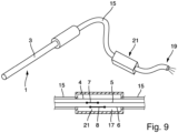
pour lequel les éléments conducteurs (7, 8) et les connexions de fils correspondantes (20) reliant les éléments conducteurs (7, 8) aux fils (5, 6) sont protégés par un boîtier d'encapsulation (21), les éléments conducteurs (7, 8) protégés par le boîtier d'encapsulation (21) étant de préférence insérés dans un câble d'extension flexible (15).
Priority Applications (3)
| Application Number | Priority Date | Filing Date | Title |
|---|---|---|---|
| EP21215112.0A EP4198475B1 (fr) | 2021-12-16 | 2021-12-16 | Sonde de température et procédé de fabrication d'une sonde de température |
| CN202211618786.4A CN116399463A (zh) | 2021-12-16 | 2022-12-15 | 温度探针和用于制造温度探针的方法 |
| US18/066,431 US12352636B2 (en) | 2021-12-16 | 2022-12-15 | Temperature probe and method for manufacturing a temperature probe |
Applications Claiming Priority (1)
| Application Number | Priority Date | Filing Date | Title |
|---|---|---|---|
| EP21215112.0A EP4198475B1 (fr) | 2021-12-16 | 2021-12-16 | Sonde de température et procédé de fabrication d'une sonde de température |
Publications (2)
| Publication Number | Publication Date |
|---|---|
| EP4198475A1 EP4198475A1 (fr) | 2023-06-21 |
| EP4198475B1 true EP4198475B1 (fr) | 2025-02-05 |
Family
ID=78918564
Family Applications (1)
| Application Number | Title | Priority Date | Filing Date |
|---|---|---|---|
| EP21215112.0A Active EP4198475B1 (fr) | 2021-12-16 | 2021-12-16 | Sonde de température et procédé de fabrication d'une sonde de température |
Country Status (3)
| Country | Link |
|---|---|
| US (1) | US12352636B2 (fr) |
| EP (1) | EP4198475B1 (fr) |
| CN (1) | CN116399463A (fr) |
Families Citing this family (1)
| Publication number | Priority date | Publication date | Assignee | Title |
|---|---|---|---|---|
| EP4198475B1 (fr) * | 2021-12-16 | 2025-02-05 | Endress+Hauser Wetzer GmbH+CO. KG | Sonde de température et procédé de fabrication d'une sonde de température |
Family Cites Families (10)
| Publication number | Priority date | Publication date | Assignee | Title |
|---|---|---|---|---|
| DE2308823C3 (de) * | 1973-02-22 | 1978-11-30 | Kraftwerk Union Ag, 4330 Muelheim | Niveaustandsmeßeinrichtung |
| US5088835A (en) * | 1990-12-31 | 1992-02-18 | Gordon Shigezawa | Reusable probe connector apparatus |
| US9671295B2 (en) * | 2014-04-22 | 2017-06-06 | Okazaki Manufacturing Company | Terminal head of sheath type temperature sensor |
| JP6150971B1 (ja) * | 2017-02-10 | 2017-06-21 | 株式会社岡崎製作所 | 測温抵抗体センサ及びその製作方法 |
| CN115468626B (zh) * | 2017-07-27 | 2025-11-04 | 沃特洛电气制造公司 | 用于测量和控制加热器系统性能的传感器系统和集成加热器-传感器 |
| DE102017130135A1 (de) * | 2017-12-15 | 2019-06-19 | Endress + Hauser Wetzer Gmbh + Co. Kg | Zustandsüberwachung eines Temperatursensors |
| CN110806172B (zh) * | 2019-12-06 | 2025-08-08 | 中国工程物理研究院化工材料研究所 | 传感器及其制备方法及集成化应变温度传感测量系统 |
| CN111006802B (zh) * | 2019-12-17 | 2021-07-27 | 华中科技大学 | 一种多模态可变胞柔性传感器及信号采集系统 |
| CN112525367B (zh) * | 2020-11-12 | 2022-08-16 | 山东科技大学 | 一种应用于海洋环境的远距离温度测量装置及测量方法 |
| EP4198475B1 (fr) * | 2021-12-16 | 2025-02-05 | Endress+Hauser Wetzer GmbH+CO. KG | Sonde de température et procédé de fabrication d'une sonde de température |
-
2021
- 2021-12-16 EP EP21215112.0A patent/EP4198475B1/fr active Active
-
2022
- 2022-12-15 CN CN202211618786.4A patent/CN116399463A/zh active Pending
- 2022-12-15 US US18/066,431 patent/US12352636B2/en active Active
Also Published As
| Publication number | Publication date |
|---|---|
| US12352636B2 (en) | 2025-07-08 |
| CN116399463A (zh) | 2023-07-07 |
| EP4198475A1 (fr) | 2023-06-21 |
| US20230194357A1 (en) | 2023-06-22 |
Similar Documents
| Publication | Publication Date | Title |
|---|---|---|
| US10119867B2 (en) | Multichannel thermocouple compensation for three dimensional temperature gradient | |
| RU2757064C1 (ru) | Датчик теплового потока с повышенным теплообменом | |
| EP2577245B1 (fr) | Transmetteur variable en processus à détection de polarité de thermocouple | |
| JP2019529928A (ja) | 熱流束センサ | |
| EP2203727B1 (fr) | Fil d'extension de thermocouple | |
| US10288490B2 (en) | Mineral insulated sheathed assembly with grounded and ungrounded temperature sensors | |
| CN107209064B (zh) | 温度探针 | |
| EP3548855A1 (fr) | Diagnostic de thermocouple court-circuité | |
| US3956936A (en) | Temperature-measuring system | |
| US12352636B2 (en) | Temperature probe and method for manufacturing a temperature probe | |
| CN105209873A (zh) | 通过增加导线的电阻来测量线圈的均匀温度 | |
| NO319794B1 (no) | Probe-anordning for apparat for overvaking av et materiales korrosjon | |
| EP3969862B1 (fr) | Amélioration de la stabilité d'un détecteur de température de résistance | |
| Desmarais et al. | How to select and use the right temperature sensor | |
| JP3118621B2 (ja) | 測温機能付きカプセル型ひずみゲージ | |
| JP6484462B2 (ja) | 温度計測システム | |
| EP0327252A2 (fr) | Fixation d'un détecteur de température à résistance | |
| CN112798129B (zh) | 一种测温装置 | |
| RU2081400C1 (ru) | Способ определения уровня жидких сред и устройство для его осуществления | |
| EP3772638A1 (fr) | Fil de capteur thermique et son procédé d'assemblage | |
| Resistors | RESISTANCE THERMOMETER THEORY AND PRACTICE | |
| EP3037793A1 (fr) | Système de thermocouple et procédé de mesure de température de processus | |
| Connolly | Industrial Resistance Thermometers | |
| Henderson | Practical Temperature Measurements | |
| JPH07174639A (ja) | 熱電対補償導線 |
Legal Events
| Date | Code | Title | Description |
|---|---|---|---|
| PUAI | Public reference made under article 153(3) epc to a published international application that has entered the european phase |
Free format text: ORIGINAL CODE: 0009012 |
|
| STAA | Information on the status of an ep patent application or granted ep patent |
Free format text: STATUS: THE APPLICATION HAS BEEN PUBLISHED |
|
| STAA | Information on the status of an ep patent application or granted ep patent |
Free format text: STATUS: REQUEST FOR EXAMINATION WAS MADE |
|
| AK | Designated contracting states |
Kind code of ref document: A1 Designated state(s): AL AT BE BG CH CY CZ DE DK EE ES FI FR GB GR HR HU IE IS IT LI LT LU LV MC MK MT NL NO PL PT RO RS SE SI SK SM TR |
|
| 17P | Request for examination filed |
Effective date: 20230606 |
|
| RBV | Designated contracting states (corrected) |
Designated state(s): AL AT BE BG CH CY CZ DE DK EE ES FI FR GB GR HR HU IE IS IT LI LT LU LV MC MK MT NL NO PL PT RO RS SE SI SK SM TR |
|
| GRAP | Despatch of communication of intention to grant a patent |
Free format text: ORIGINAL CODE: EPIDOSNIGR1 |
|
| STAA | Information on the status of an ep patent application or granted ep patent |
Free format text: STATUS: GRANT OF PATENT IS INTENDED |
|
| RIC1 | Information provided on ipc code assigned before grant |
Ipc: G01K 1/08 20210101ALI20240723BHEP Ipc: G01K 7/18 20060101AFI20240723BHEP |
|
| INTG | Intention to grant announced |
Effective date: 20240823 |
|
| GRAS | Grant fee paid |
Free format text: ORIGINAL CODE: EPIDOSNIGR3 |
|
| GRAA | (expected) grant |
Free format text: ORIGINAL CODE: 0009210 |
|
| STAA | Information on the status of an ep patent application or granted ep patent |
Free format text: STATUS: THE PATENT HAS BEEN GRANTED |
|
| AK | Designated contracting states |
Kind code of ref document: B1 Designated state(s): AL AT BE BG CH CY CZ DE DK EE ES FI FR GB GR HR HU IE IS IT LI LT LU LV MC MK MT NL NO PL PT RO RS SE SI SK SM TR |
|
| REG | Reference to a national code |
Ref country code: GB Ref legal event code: FG4D |
|
| REG | Reference to a national code |
Ref country code: CH Ref legal event code: EP |
|
| REG | Reference to a national code |
Ref country code: DE Ref legal event code: R096 Ref document number: 602021025750 Country of ref document: DE |
|
| REG | Reference to a national code |
Ref country code: IE Ref legal event code: FG4D |
|
| P01 | Opt-out of the competence of the unified patent court (upc) registered |
Free format text: CASE NUMBER: APP_7728/2025 Effective date: 20250214 |
|
| REG | Reference to a national code |
Ref country code: NL Ref legal event code: MP Effective date: 20250205 |
|
| PG25 | Lapsed in a contracting state [announced via postgrant information from national office to epo] |
Ref country code: RS Free format text: LAPSE BECAUSE OF FAILURE TO SUBMIT A TRANSLATION OF THE DESCRIPTION OR TO PAY THE FEE WITHIN THE PRESCRIBED TIME-LIMIT Effective date: 20250505 |
|
| PG25 | Lapsed in a contracting state [announced via postgrant information from national office to epo] |
Ref country code: FI Free format text: LAPSE BECAUSE OF FAILURE TO SUBMIT A TRANSLATION OF THE DESCRIPTION OR TO PAY THE FEE WITHIN THE PRESCRIBED TIME-LIMIT Effective date: 20250205 |
|
| PG25 | Lapsed in a contracting state [announced via postgrant information from national office to epo] |
Ref country code: PL Free format text: LAPSE BECAUSE OF FAILURE TO SUBMIT A TRANSLATION OF THE DESCRIPTION OR TO PAY THE FEE WITHIN THE PRESCRIBED TIME-LIMIT Effective date: 20250205 |
|
| PG25 | Lapsed in a contracting state [announced via postgrant information from national office to epo] |
Ref country code: ES Free format text: LAPSE BECAUSE OF FAILURE TO SUBMIT A TRANSLATION OF THE DESCRIPTION OR TO PAY THE FEE WITHIN THE PRESCRIBED TIME-LIMIT Effective date: 20250205 |
|
| REG | Reference to a national code |
Ref country code: LT Ref legal event code: MG9D |
|
| PG25 | Lapsed in a contracting state [announced via postgrant information from national office to epo] |
Ref country code: NO Free format text: LAPSE BECAUSE OF FAILURE TO SUBMIT A TRANSLATION OF THE DESCRIPTION OR TO PAY THE FEE WITHIN THE PRESCRIBED TIME-LIMIT Effective date: 20250505 Ref country code: IS Free format text: LAPSE BECAUSE OF FAILURE TO SUBMIT A TRANSLATION OF THE DESCRIPTION OR TO PAY THE FEE WITHIN THE PRESCRIBED TIME-LIMIT Effective date: 20250605 |
|
| PG25 | Lapsed in a contracting state [announced via postgrant information from national office to epo] |
Ref country code: NL Free format text: LAPSE BECAUSE OF FAILURE TO SUBMIT A TRANSLATION OF THE DESCRIPTION OR TO PAY THE FEE WITHIN THE PRESCRIBED TIME-LIMIT Effective date: 20250205 |
|
| PG25 | Lapsed in a contracting state [announced via postgrant information from national office to epo] |
Ref country code: HR Free format text: LAPSE BECAUSE OF FAILURE TO SUBMIT A TRANSLATION OF THE DESCRIPTION OR TO PAY THE FEE WITHIN THE PRESCRIBED TIME-LIMIT Effective date: 20250205 |
|
| PG25 | Lapsed in a contracting state [announced via postgrant information from national office to epo] |
Ref country code: LV Free format text: LAPSE BECAUSE OF FAILURE TO SUBMIT A TRANSLATION OF THE DESCRIPTION OR TO PAY THE FEE WITHIN THE PRESCRIBED TIME-LIMIT Effective date: 20250205 Ref country code: PT Free format text: LAPSE BECAUSE OF FAILURE TO SUBMIT A TRANSLATION OF THE DESCRIPTION OR TO PAY THE FEE WITHIN THE PRESCRIBED TIME-LIMIT Effective date: 20250605 |
|
| PG25 | Lapsed in a contracting state [announced via postgrant information from national office to epo] |
Ref country code: BG Free format text: LAPSE BECAUSE OF FAILURE TO SUBMIT A TRANSLATION OF THE DESCRIPTION OR TO PAY THE FEE WITHIN THE PRESCRIBED TIME-LIMIT Effective date: 20250205 Ref country code: GR Free format text: LAPSE BECAUSE OF FAILURE TO SUBMIT A TRANSLATION OF THE DESCRIPTION OR TO PAY THE FEE WITHIN THE PRESCRIBED TIME-LIMIT Effective date: 20250506 |
|
| REG | Reference to a national code |
Ref country code: AT Ref legal event code: MK05 Ref document number: 1764961 Country of ref document: AT Kind code of ref document: T Effective date: 20250205 |
|
| PG25 | Lapsed in a contracting state [announced via postgrant information from national office to epo] |
Ref country code: SE Free format text: LAPSE BECAUSE OF FAILURE TO SUBMIT A TRANSLATION OF THE DESCRIPTION OR TO PAY THE FEE WITHIN THE PRESCRIBED TIME-LIMIT Effective date: 20250205 |
|
| PG25 | Lapsed in a contracting state [announced via postgrant information from national office to epo] |
Ref country code: SM Free format text: LAPSE BECAUSE OF FAILURE TO SUBMIT A TRANSLATION OF THE DESCRIPTION OR TO PAY THE FEE WITHIN THE PRESCRIBED TIME-LIMIT Effective date: 20250205 |
|
| PG25 | Lapsed in a contracting state [announced via postgrant information from national office to epo] |
Ref country code: DK Free format text: LAPSE BECAUSE OF FAILURE TO SUBMIT A TRANSLATION OF THE DESCRIPTION OR TO PAY THE FEE WITHIN THE PRESCRIBED TIME-LIMIT Effective date: 20250205 |
|
| PG25 | Lapsed in a contracting state [announced via postgrant information from national office to epo] |
Ref country code: AT Free format text: LAPSE BECAUSE OF FAILURE TO SUBMIT A TRANSLATION OF THE DESCRIPTION OR TO PAY THE FEE WITHIN THE PRESCRIBED TIME-LIMIT Effective date: 20250205 |
|
| PG25 | Lapsed in a contracting state [announced via postgrant information from national office to epo] |
Ref country code: EE Free format text: LAPSE BECAUSE OF FAILURE TO SUBMIT A TRANSLATION OF THE DESCRIPTION OR TO PAY THE FEE WITHIN THE PRESCRIBED TIME-LIMIT Effective date: 20250205 Ref country code: CZ Free format text: LAPSE BECAUSE OF FAILURE TO SUBMIT A TRANSLATION OF THE DESCRIPTION OR TO PAY THE FEE WITHIN THE PRESCRIBED TIME-LIMIT Effective date: 20250205 |
|
| PG25 | Lapsed in a contracting state [announced via postgrant information from national office to epo] |
Ref country code: RO Free format text: LAPSE BECAUSE OF FAILURE TO SUBMIT A TRANSLATION OF THE DESCRIPTION OR TO PAY THE FEE WITHIN THE PRESCRIBED TIME-LIMIT Effective date: 20250205 |
|
| PG25 | Lapsed in a contracting state [announced via postgrant information from national office to epo] |
Ref country code: SK Free format text: LAPSE BECAUSE OF FAILURE TO SUBMIT A TRANSLATION OF THE DESCRIPTION OR TO PAY THE FEE WITHIN THE PRESCRIBED TIME-LIMIT Effective date: 20250205 |
|
| REG | Reference to a national code |
Ref country code: DE Ref legal event code: R097 Ref document number: 602021025750 Country of ref document: DE |
|
| PLBE | No opposition filed within time limit |
Free format text: ORIGINAL CODE: 0009261 |
|
| STAA | Information on the status of an ep patent application or granted ep patent |
Free format text: STATUS: NO OPPOSITION FILED WITHIN TIME LIMIT |
|
| PGFP | Annual fee paid to national office [announced via postgrant information from national office to epo] |
Ref country code: DE Payment date: 20251211 Year of fee payment: 5 |
|
| 26N | No opposition filed |
Effective date: 20251106 |
|
| PGFP | Annual fee paid to national office [announced via postgrant information from national office to epo] |
Ref country code: IT Payment date: 20251223 Year of fee payment: 5 |