EP4199022B1 - Dispositif d'extinction d'arc triphasé avec deux pistons - Google Patents
Dispositif d'extinction d'arc triphasé avec deux pistons Download PDFInfo
- Publication number
- EP4199022B1 EP4199022B1 EP21215547.7A EP21215547A EP4199022B1 EP 4199022 B1 EP4199022 B1 EP 4199022B1 EP 21215547 A EP21215547 A EP 21215547A EP 4199022 B1 EP4199022 B1 EP 4199022B1
- Authority
- EP
- European Patent Office
- Prior art keywords
- piston
- busbar
- pistons
- busbars
- actuator
- Prior art date
- Legal status (The legal status is an assumption and is not a legal conclusion. Google has not performed a legal analysis and makes no representation as to the accuracy of the status listed.)
- Active
Links
Images

Classifications
-
- H—ELECTRICITY
- H01—ELECTRIC ELEMENTS
- H01H—ELECTRIC SWITCHES; RELAYS; SELECTORS; EMERGENCY PROTECTIVE DEVICES
- H01H33/00—High-tension or heavy-current switches with arc-extinguishing or arc-preventing means
- H01H33/02—Details
- H01H33/04—Means for extinguishing or preventing arc between current-carrying parts
-
- H—ELECTRICITY
- H01—ELECTRIC ELEMENTS
- H01H—ELECTRIC SWITCHES; RELAYS; SELECTORS; EMERGENCY PROTECTIVE DEVICES
- H01H39/00—Switching devices actuated by an explosion produced within the device and initiated by an electric current
- H01H39/004—Closing switches
-
- H—ELECTRICITY
- H01—ELECTRIC ELEMENTS
- H01H—ELECTRIC SWITCHES; RELAYS; SELECTORS; EMERGENCY PROTECTIVE DEVICES
- H01H9/00—Details of switching devices, not covered by groups H01H1/00 - H01H7/00
- H01H9/30—Means for extinguishing or preventing arc between current-carrying parts
- H01H9/34—Stationary parts for restricting or subdividing the arc, e.g. barrier plate
- H01H9/346—Details concerning the arc formation chamber
-
- H—ELECTRICITY
- H01—ELECTRIC ELEMENTS
- H01H—ELECTRIC SWITCHES; RELAYS; SELECTORS; EMERGENCY PROTECTIVE DEVICES
- H01H33/00—High-tension or heavy-current switches with arc-extinguishing or arc-preventing means
- H01H33/70—Switches with separate means for directing, obtaining, or increasing flow of arc-extinguishing fluid
- H01H33/88—Switches with separate means for directing, obtaining, or increasing flow of arc-extinguishing fluid the flow of arc-extinguishing fluid being produced or increased by movement of pistons or other pressure-producing parts
-
- H—ELECTRICITY
- H01—ELECTRIC ELEMENTS
- H01H—ELECTRIC SWITCHES; RELAYS; SELECTORS; EMERGENCY PROTECTIVE DEVICES
- H01H9/00—Details of switching devices, not covered by groups H01H1/00 - H01H7/00
- H01H9/20—Interlocking, locking, or latching mechanisms
- H01H9/26—Interlocking, locking, or latching mechanisms for interlocking two or more switches
-
- H—ELECTRICITY
- H01—ELECTRIC ELEMENTS
- H01H—ELECTRIC SWITCHES; RELAYS; SELECTORS; EMERGENCY PROTECTIVE DEVICES
- H01H9/00—Details of switching devices, not covered by groups H01H1/00 - H01H7/00
- H01H9/20—Interlocking, locking, or latching mechanisms
- H01H9/26—Interlocking, locking, or latching mechanisms for interlocking two or more switches
- H01H2009/267—Interlocking, locking, or latching mechanisms for interlocking two or more switches with interlocking of two out of three switches, e.g. two switches each connecting a power supply to a busbar and a bus coupling switch interlocked in such a way that the power supplies are never connected in parallel
-
- H—ELECTRICITY
- H01—ELECTRIC ELEMENTS
- H01H—ELECTRIC SWITCHES; RELAYS; SELECTORS; EMERGENCY PROTECTIVE DEVICES
- H01H9/00—Details of switching devices, not covered by groups H01H1/00 - H01H7/00
- H01H9/0072—Details of switching devices, not covered by groups H01H1/00 - H01H7/00 particular to three-phase switches
-
- H—ELECTRICITY
- H01—ELECTRIC ELEMENTS
- H01H—ELECTRIC SWITCHES; RELAYS; SELECTORS; EMERGENCY PROTECTIVE DEVICES
- H01H9/00—Details of switching devices, not covered by groups H01H1/00 - H01H7/00
- H01H9/30—Means for extinguishing or preventing arc between current-carrying parts
Definitions
- the present disclosure relates to an arc quenching device for a three-phase electrical switchgear.
- an arc event In a switchgear, an arc event, even for a relatively short duration, can result in major damages.
- An arc can be quenched by short circuiting all phases, to each other (and optionally to ground).
- the duration of the arc should be reduced.
- a circuit breaker can interrupt fault currents arising from internal arcs.
- the opening time of the circuit breaker may be relatively long, e.g. 30 to 60 ms.
- a pyrotechnical actuator may be used.
- EP 3 696 842 discloses a single phase electrical closing switch for grounding one phase using a pyrotechnical actuator to drive a movable piston to electrically connect both a phase electrode and a ground electrode.
- Document DE 102 54 497 discloses a device according to the preamble of claim 1.
- an arc quenching device for a three-phase electrical switchgear.
- the device comprises a first busbar, a second busbar and a third busbar, each of a respective phase of the three-phase switchgear.
- the device also comprises a first piston and a second piston, each of an electrically conductive material.
- the device also comprises at least one pyrotechnical actuator arranged with the first and second pistons to axially move each of the first and second pistons if the at least one pyrotechnical actuator is fired.
- the first and second pistons are arranged in relation to the first, second and third busbars such that said axial movement brings the first piston into contact with both the first busbar and the second busbar, short-circuiting the first and second busbars via the first piston, and the second piston into contact with both the first busbar and the third busbar, short-circuiting the first and third busbars via the second piston.
- a three-phase electrical switchgear comprising the device of any preceding claim and a fault clearing breaker arranged to break a current of each of the three phases to which the first, second and third busbars, respectively, are connected
- FIG. 1 illustrates a three-phase electrical switchgear 10 comprising a breaker 11, e.g. a fault clearing breaker, arranged to break the current of each of the three phases/phase lines L1, L2 and L3.
- the switchgear 10 may e.g. be arranged to break the current to a load, in which case the switchgear may be arranged between a power distribution system, at a line side of the switchgear, and at least one load, at a load side of the switchgear.
- the switchgear may be arranged for low or medium voltage applications, implying that the Alternating Current (AC) phase-to-phase voltage of the phases L1, L2 and L3 is within the medium or low voltage range, e.g. within the range of 0.1-50 kV, or within the low voltage range of 0.1-1 kV.
- AC Alternating Current
- the breaker 11 may typically be able to clear an arc fault, i.e. to break the current in the phases L1, L2 and L3, within a time range of 30-60 ms after detection of the arc fault. This may be too slow to avoid damages resulting from the arc fault.
- the arc quenching device 1 is arranged in the switchgear 10 and able to short-circuit all the phases L1, L2 and L3 much faster, e.g. within a time range of 0.1-5 ms, preferably 0.1-2 ms, after detection of an arc.
- the arc quenching device 1 is connected to each of the phases L1, L2 and L3 of the switchgear via electrical conductors.
- the device 1 comprises phase busbars 5 (herein also called busbars) electrically connected to the phase lines of the switchgear 10.
- the arc quenching device 1 is configured to quench an arc by short-circuiting all the three busbars T, S and R, to each other (and optionally also to ground), thus short-circuiting the three phases L1, L2 and L3 to each other.
- the switchgear 10 comprises an arc fault detector 13 connected to an arc fault sensor 12, e.g. an optical, current, pressure and/or heat sensor configured to detect an electrical arc in the switchgear, e.g. between two of the phases L1, L2 and L3, between a phase and ground, or generally within the switchgear 10.
- an arc fault detector 13 detects an arc via the sensor 12
- the detector 13 sends a firing signal 14 to the arc quenching device 1, causing the at least one pyrotechnical actuator 3 (see figures 2 ) of the device 1 to fire.
- Figures 2a and 2b illustrate open and closed positions, respectively, of one of the pistons P of the arc quenching device 1.
- the piston has a back end 24 facing away from the direction of the axial movement as indicated by the down-pointing arrow in figure 2a , a front end 23 facing in the direction of said axial movement, and a lateral surface 21. What is discussed about the piston P shown in figures 2a and 2b is also valid for the other piston P of the device 1.
- the piston P is of an electrically conductive material, enabling the piston to short-circuit the busbars 5 via the piston by the lateral surface 21 of the piston making electrical contact with the busbars 5.
- the piston P may typically have a circular cross-section.
- the piston is arranged with a pyrotechnical actuator 3 which, when fired, forms an expanding gas which pushes the, previously stationary, piston P along its longitudinal axis 20 in a direction away from the actuator 3 (in the direction indicated by the axial arrow in the figure, below the piston).
- the actuator 3 is arranged to axially move the piston P from its open position, e.g. as illustrated in figure 2a , to its closed position, e.g. as illustrated in figure 2b , through one opening 6 (as in figures 2a, 2b and 6 ), or a plurality of axially arranged openings 6 (as in the examples of figures 3-5 and 7 ).
- the opening 6, or each of the openings 6, may be a hole, through hole or blind hole, in a busbar 5, or an opening between two different, and from each other electrically isolated, busbars 5a and 5b (as in the example of figures 2a and 2b ).
- a housing 4 may be arranged around the piston P, providing a sealed-off chamber 7 between the back end 24 of the piston P and the inside of the housing 4, preferably during the whole axial movement of the piston.
- gas may be formed within the chamber 7 which pushes on the back end 24 of the piston P, axially moving the piston and expanding the chamber 7.
- the actuator may itself comprise a moving part which, when the pyrotechnical actuator is fired, is axially pressed against the piston P, in physical contact therewith, to cause the axial movement of the piston.
- the gas expansion may occur in a chamber within the actuator 3 rather than in a chamber 7 between the actuator 3 and the back end 24 of the piston P.
- the piston P has a tapered shape, tapering towards the front end 23 of the piston, e.g. at an angle ⁇ to the longitudinal axis 20 within the range of 3-12°, preferably 4-8°, e.g. 5.5-6.5°.
- the piston has a conical shape, e.g. a truncated or frustoconical shape as in the figures.
- a conical piston typically has a circular base, forming an end surface of the back end 24 of the piston.
- the cone is right circular.
- the angle ⁇ between a generatrix line of the lateral surface 21 and the central longitudinal axis 20 may thus be within the range of 3-12°, preferably 4-8°, e.g. 5.5-6.5°.
- the inner surfaces of the opening(s) 6 are arranged to fit against the tapered shape of the piston P, for improved electrical connection.
- the opening 6 is a hole in a busbar 5
- the hole may be tapered with the same angle ⁇ to the longitudinal axis 20 as the piston P to fit against the lateral surface 21 at the end of the axial movement of the piston (corresponding to the closed position of the piston P and a closed state of the device 1).
- the hole 6 has a shape (typically circular) and size (in a plane perpendicular to the longitudinal axis 20) which correspond to a cross-section of the piston such that, when the piston has reached its closed position, the inside surface of the hole contacts the lateral surface 21 of the piston around the whole circumference of the piston.
- each of the respective end surfaces 22 of the two busbars 5a and 5b may slant with the same angle ⁇ to the axis 20 as the piston P to fit against the lateral surface 21 at the end of the axial movement of the piston (corresponding to the closed position of the piston P and a closed state of the device 1). Additionally or alternatively, each of the respective end surfaces 22 of the two busbars 5a and 5b may be curved in the plane perpendicular to the longitudinal axis 20 to continuously contact around a section of the circumference of the piston when it has reached its closed position.
- the piston may be provided with a guide 8 which is axially extending from the front end 23 of the piston.
- the guide 8 is of an electrically insulating material.
- the guide 8 is typically cylindrical, e.g. with a circular cross-section.
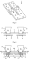
- Figures 3 and 4 illustrate an embodiment of the arc quenching device 1 where a first piston P1 and a second piston P2 are each arranged to axially move through a respective opening 6 in the form of a first or second through hole in the first busbar T.
- Each of the second busbar S and the third busbar R is arranged with an opening 6 in the form of a hole (a through hole or blind hole) in axial alignment with a respective one of the through holes of the first busbar T to receive the first or second piston P1 or P2.
- each of the pistons P1 and P2 are in their respective open positions where all of the three busbars T, S and Rare electrically insulated from each other at the opening(s) 6, e.g. by an electrically insulating gas in the opening(s) 6, such as air or by another electrically insulating gas/gas mixture, for instance (pure) nitrogen.
- an electrically insulating gas in the opening(s) 6, such as air or by another electrically insulating gas/gas mixture, for instance (pure) nitrogen.
- the first busbar T, and thus the first and second holes 6 therein is in relation to the axial movement of the pistons arranged before (above, in the figures) the holes of the second and third busbars S and R, respectively.
- the pistons P1 and/or P2 may be in contact with the first busbar T, but not with either of the second busbar S and the third busbar R, or the pistons P1 and/or P2 may not be in contact with any of the busbars T, S or R.
- the first busbar T, and thus the first and second holes 6 therein may in relation to the axial movement of the pistons be arranged after (below, in the figures 3 and 4 ) the holes of the second and third busbars S and R, respectively.
- the first and second pistons P1 and P2 simultaneously move axially until each of them reaches its closed position, closing the arc quenching device 1.
- the first piston P1 In its closed position, the first piston P1 is in physical (and thus electrical) contact with both the first busbar T and the second busbar S.
- the lateral surface 21 of the first piston P1 is in physical contact with the inside surface of the first hole 6 through the first busbar T and with the inside surface of the hole 6 through or in the second busbar S.
- the second piston P2 is in physical (and thus electrical) contact with both the first busbar T and the third busbar R.
- the lateral surface 21 of the second piston P2 is in physical contact with the inside surface of the second hole 6 through the first busbar T and with the inside surface of the hole 6 through or in the third busbar R.
- the device 1 is arranged such that, after the axial movement of the first and second pistons P1 and P2, the lateral surface 21 of the first piston P1 contacts respective inner surfaces of the first hole 6 in the first busbar T and the hole 6 in the second busbar S, and the lateral surface 21 of the second piston P2 contacts respective inner surfaces of a second hole 6 in the first busbar T and a hole 6 in the third busbar R.
- the holes 6 of the busbars T, S and R are preferably shaped to fit against the pistons P1 and P2 when in their closed positions, such that the pistons, by their axial movements, are wedged against the busbars to cause a good electrical contact.
- each of the first and second pistons P1 and P2 has a right circular conical shape, tapering towards its front end 23 (downward in figure 4 )
- each of the holes 6 in the first, second and third busbars T, S and R may be circular and have an inner surface with corresponding tapering, i.e. tapering in the direction of the axial movement.
- the first and second holes 6 of the first busbar T are arranged before the axially arranged holes 6 of the second and third busbars S and R, respectively (as shown in figure 4 ), the first and second holes in the first busbar T preferably each has a larger diameter than the axially arranged later hole of the second or third busbar S or R.
- Figure 5 illustrates an embodiment which is similar to the embodiments of figures 3 and 4 , but with also a Protective Earth (PE) busbar.
- the PE busbar forms a third layer of busbars, in addition to the two layers of busbars in figures 3 and 4 .
- the PE busbar may (in the direction of the axial movement) be arranged before (above, in figure 5 ) the first busbar T.
- first piston P1 and the second piston P2 are each arranged to axially move through a respective opening 6 in the form of a first or second, respectively, through hole in the PE busbar, which through holes 6 are axially aligned with the first and second through holes 6 of the first busbar T.
- Each of a second busbar S and a third busbar Rare arranged with an opening 6 in the form of a hole (a through hole or blind hole) in axial alignment with a respective one of the through holes of the PE busbar and of the first busbar T to receive the first or second piston P1 or P2.
- the first piston P1 in its closed position, the first piston P1 is in physical (and thus electrical) contact with the PE busbar as well as with both the first busbar T and the second busbar S.
- the lateral surface 21 of the first piston P1 is in physical contact with the inside surface of the first hole 6 through the PE busbar as well as with both the inside surface of the first hole 6 through the first busbar T and the inside surface of the hole 6 through/in the second busbar S.
- the second piston P2 in physical (and thus electrical) contact with the PE busbar as well as with both the first busbar T and the third busbar R.
- the lateral surface 21 of the second piston P2 is in physical contact with the inside surface of the second hole 6 through the PE busbar as well as with the inside surface of the second hole 6 through the first busbar T and the inside surface of the hole 6 through/in the third busbar R.
- the arc quenching device 1 comprises a protective earth busbar PE arranged such that, when the at least one pyrotechnical actuator 3 is fired, the first and second pistons P1 and P2 are each axially moved until each of the pistons also contacts the protective earth busbar such that each of the first, second and third busbars T, S and R are also short-circuited to the protective earth busbar PE via at least one of the first and second pistons.
- each piston P may be provided with a guide 8 of an electrically insulating material, to aid the piston to pass through the openings 6.
- each piston is arranged to electrically contact busbars of more than two axially aligned openings 6, e.g. holes through the PE busbar, the first busbar T and the second or third busbar S or R as in the example of figure 5 .
- the guide 8 may then ensure that the piston makes physical and electrical contact with all the busbars it is arranged to contact at its closed position at the same time. If a piston P contacts only two busbars, e.g. PE and T in figure 5 , there is a risk that the piston is delayed or prevented from making contact with all the busbars it is arranged to contact at its closed position, e.g. by welding taking place to the two first contacted busbars.
- the guide 8 of the piston may be arranged to pass through a guide hole 51 in an insulator 50 of an electrically insulating material, arranged on the other side of the openings 6 as seen in the direction of the axial movement of the piston.
- the front end of the guide 8 may extend into its guide hole 51 of the insulator 50 when the piston is in its open position, and may then then pass further into or through the guide hole during the axial movement until the piston has reached its closed position.
- the piston may be prevented from moving at an angle to the longitudinal axis 20, or from tilting, during its axial movement.
- Figure 6 illustrates another embodiment of the present invention, in which the lateral surfaces 21 of the pistons P1 and P2, instead of being arranged to contact inner surfaces of holes 6 in the first, second and third busbars T, S and R (the inner surface of each hole fully surrounding the piston in the closed position), are arranged to contact end surfaces 22 of each of the first, second and third busbars T, S and R (each end surface 22 only extending along/contacting a section of the circumference of the piston in the closed position).
- the device 1 is arranged such that, after the axial movement of the first and second pistons P1 and P2, the lateral surface 21 of the first piston P1 contacts respective end surfaces 22 of the first busbar T and the second busbar S, and the lateral surface 21 of the second piston P2 contacts respective end surfaces 22 of the first busbar T and the third busbar R.
- the first, second and third busbars T, S and R, or at least end pars thereof including the end surfaces 22, may be arranged in the same plane perpendicular to the longitudinal axes 20 of the pistons.
- each of the respective end surfaces 22 of the two busbars T and S (for the first piston P1), and T and R (for the second piston P2) may slant with the same angle ⁇ as the piston P1 or P2 tapers to fit against the lateral surface 21 at the closed position of the piston. Additionally or alternatively, each of the respective end surfaces 22 of the two busbars T and S (for the first piston P1), and T and R (for the second piston), may be curved in the plane perpendicular to the longitudinal axis 20 to continuously contact a section of the circumference of the piston when it has reached its closed position.
- each of the end surfaces 22 of the first, second and third busbars T, S and R are curved to fit against the lateral surface 21 of the first piston P1 or the second piston P2 with which it is arranged to make contact.
- At least one pyrotechnical actuator 3 is used.
- An advantage with a pyrotechnical actuator is the short time it takes to short circuit the three phases, e.g. within 5, 4 or 2 ms from detection of an arc fault.
- the at least one pyrotechnical actuator 3 may in some embodiments consist of two actuators 3, one per piston of the first and second pistons P1 and P2.
- the at least one pyrotechnical actuator 3 comprises or consists of a first actuator, arranged to move the first piston P1 but not the second piston, and a second actuator, arranged to move the second piston P2 but not the first piston.
- the first and second actuators 3 may be synchronized. It is however noted that the first and second pistons P1 and P2 may move at slightly different times and/or speeds, e.g. within 1-10 ⁇ s of each other, since the gas pressure build-up may vary slightly.
- the at least one pyrotechnical actuator 3 consists of only one actuator, arranged to move both the first piston P1 and the second piston P2.
- the first and second pistons P1 and P2 may be rigidly mechanically connected to each other such that they do not move in relation to each other during the axial movement by the actuator 3.
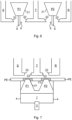
- Figure 7 illustrates an example of an embodiment where only one actuator 3 is used for both of the first and second pistons P1 and P2.
- the first and second pistons P1 and P2 are rigidly mechanically connected to each other and are arranged to axially move together (upwards in the figure) driven by the single actuator 3 to contact the first, second and third busbars T, S and R via end surfaces 22 thereof, optionally through first and second through holes 6 of a PE busbar.
- the end surfaces 22, as well as the through holes 6, may be as discussed above in relation to other figures.
Landscapes
- Physics & Mathematics (AREA)
- Electromagnetism (AREA)
- Circuit Breakers (AREA)
Claims (14)
- Dispositif d'extinction d'arc (1) pour un appareillage de commutation électrique triphasé (10), le dispositif comprenant :une première barre omnibus (T), une deuxième barre omnibus (S) et une troisième barre omnibus (R), chacune d'une phase respective (L1, L2, L3) de l'appareillage de commutation triphasé ;un premier piston (P1) caractérisé en ce que ledit dispositif (1) comprend en outre un second piston (P2), chaque piston étant d'un matériau électroconducteur ; etau moins un actionneur pyrotechnique (3) agencé avec les premier et second pistons pour mouvoir axialement chacun des premier et second pistons si l'au moins un actionneur pyrotechnique est déclenché ;dans lequel les premier et second pistons (P1, P2) sont agencés relativement aux première, deuxième, et troisième barres omnibus (T, S, R) de telle sorte que ledit mouvement axial mette le premier piston (P1) en contact à la fois avec la première barre omnibus (T) et avec la deuxième barre omnibus (S), court-circuitant les première et deuxième barres omnibus par l'intermédiaire du premier piston, et le second piston (P2) en contact à la fois avec la première barre omnibus (T) et avec la troisième barre omnibus (R), court-circuitant les première et troisième barres omnibus par l'intermédiaire du second piston.
- Dispositif de la revendication 1, comprenant en outre une barre omnibus de protection par mise à la terre (PE) agencée de telle sorte que, lorsque l'au moins un actionneur pyrotechnique (3) est déclenché, les premier et second pistons (P1, P2) soient chacun axialement mus jusqu'à ce que chacun des pistons entre également en contact avec la barre omnibus de protection par mise à la terre de telle sorte que chacune des première, deuxième, et troisième barres omnibus (T, S, R) soit également court-circuitée vers la barre omnibus de protection par mise à la terre par l'intermédiaire d'au moins un des premier et second pistons.
- Dispositif de la revendication 1 ou 2, dans lequel l'au moins un actionneur pyrotechnique (3) comprend ou est constitué d'un premier actionneur, agencé pour mouvoir le premier piston (P1) et non le second piston, et un second actionneur, agencé pour mouvoir le second piston (P2) et non le premier piston.
- Dispositif de la revendication 3, dans lequel les premier et second actionneurs (3) sont synchronisés pour se déclencher en même temps.
- Dispositif de la revendication 1 ou 2, dans lequel l'au moins un actionneur pyrotechnique (3) est constitué d'un seul actionneur, agencé pour mouvoir à la fois le premier et le second piston (P1, P2).
- Dispositif de la revendication 5, dans lequel les premier et second pistons (P1, P2) sont reliés l'un à l'autre de façon rigidement mécanique de telle sorte qu'ils ne se meuvent pas l'un relativement à l'autre lorsqu'ils sont axialement mus par l'actionneur (3).
- Dispositif d'une quelconque revendication précédente, dans lequel chacun des premier et second pistons (P1, P2) a une forme effilée, par exemple une forme conique telle qu'une forme tronconique, s'effilant vers son extrémité avant (23).
- Dispositif d'une quelconque revendication précédente, dans lequel le dispositif (1) est agencé de telle sorte que, après le mouvement axial des premier et second pistons (P1, P2), une surface latérale (21) du premier piston (P1) entre en contact avec des surfaces intérieures respectives d'un premier trou (6) dans la première barre omnibus (T) et d'un trou (6) dans la deuxième barre omnibus (S), et une surface latérale (21) du second piston (P2) entre en contact avec des surfaces intérieures respectives d'un second trou (6) dans la première barre omnibus (T) et d'un trou (6) dans la troisième barre omnibus (R).
- Dispositif de la revendication 8, dans lequel chacun des premier et second trous (6) de la première barre omnibus (T), du trou (6) dans la deuxième barre omnibus (S) et du trou (6) dans la troisième barre omnibus (R) est effilé pour s'ajuster contre la surface latérale (21) du premier piston (P1) ou du second piston (P2) avec laquelle il est agencé pour entrer en contact.
- Dispositif d'une quelconque revendication 1 à 7, dans lequel le dispositif (1) est agencé de telle sorte que, après le mouvement axial des premier et second pistons (P1, P2), une surface latérale (21) du premier piston (P1) entre en contact avec des surfaces d'extrémité respectives (22) de la première barre omnibus (T) et de la deuxième barre omnibus (S), et une surface latérale (21) du second piston (P2) entre en contact avec des surfaces d'extrémité respectives (22) de la première barre omnibus (T) et de la troisième barre omnibus (R).
- Dispositif de la revendication 10, dans lequel chacune des surfaces d'extrémité (22) des première, deuxième, et troisième barres omnibus (T, S, R) est incurvée pour s'ajuster contre la surface latérale (21) du premier piston (P1) ou du second piston (P2) avec laquelle il est agencé pour entrer en contact.
- Dispositif d'une quelconque revendication précédente, dans lequel chacun des premier et second pistons (P1, P2) est pourvu d'un guide (8) d'un matériau électro-isolant qui s'étend axialement depuis l'extrémité avant (23) du piston.
- Appareillage de commutation électrique triphasé (10) comprenant le dispositif (1) d'une quelconque revendication précédente et un disjoncteur de déblocage de défaut (11) agencé pour couper un courant de chacune des trois phases (L1, L2, L3) auxquelles les première, deuxième, et troisième barres omnibus (T, S, R), respectivement, sont connectées.
- Appareillage de commutation de la revendication 13, agencé pour applications à basse ou moyenne tension, de préférence des applications à basse tension.
Priority Applications (3)
| Application Number | Priority Date | Filing Date | Title |
|---|---|---|---|
| EP21215547.7A EP4199022B1 (fr) | 2021-12-17 | 2021-12-17 | Dispositif d'extinction d'arc triphasé avec deux pistons |
| CN202211573266.6A CN116266517B (zh) | 2021-12-17 | 2022-12-08 | 具有两个活塞的三相灭弧设备 |
| US18/065,047 US12451302B2 (en) | 2021-12-17 | 2022-12-13 | Three-phase arc quenching device with two pistons |
Applications Claiming Priority (1)
| Application Number | Priority Date | Filing Date | Title |
|---|---|---|---|
| EP21215547.7A EP4199022B1 (fr) | 2021-12-17 | 2021-12-17 | Dispositif d'extinction d'arc triphasé avec deux pistons |
Publications (2)
| Publication Number | Publication Date |
|---|---|
| EP4199022A1 EP4199022A1 (fr) | 2023-06-21 |
| EP4199022B1 true EP4199022B1 (fr) | 2024-06-26 |
Family
ID=78957360
Family Applications (1)
| Application Number | Title | Priority Date | Filing Date |
|---|---|---|---|
| EP21215547.7A Active EP4199022B1 (fr) | 2021-12-17 | 2021-12-17 | Dispositif d'extinction d'arc triphasé avec deux pistons |
Country Status (3)
| Country | Link |
|---|---|
| US (1) | US12451302B2 (fr) |
| EP (1) | EP4199022B1 (fr) |
| CN (1) | CN116266517B (fr) |
Family Cites Families (37)
| Publication number | Priority date | Publication date | Assignee | Title |
|---|---|---|---|---|
| DE9419141U1 (de) | 1994-11-29 | 1996-03-28 | Klöckner-Moeller GmbH, 53115 Bonn | Kurzschließer zum Löschen von Störlichtbögen zur Verwendung in Schaltanlagen |
| SE9404455L (sv) | 1994-12-22 | 1996-06-23 | Asea Brown Boveri | Elektrisk kopplingsapparat |
| WO1997041582A1 (fr) | 1996-04-27 | 1997-11-06 | Dynamit Nobel Gmbh Explosivstoff- Und Systemtechnik | Element de commutation pyrotechnique pour circuits electriques |
| DE19746566A1 (de) | 1997-10-22 | 1999-04-29 | Kloeckner Moeller Gmbh | Kurzschließer, insbesondere für eine Störlichtbogen-Schutzvorrichtung zur Verwendung in Anlagen zur Verteilung elektrischer Energie |
| DE19746813A1 (de) | 1997-10-23 | 1999-04-29 | Kloeckner Moeller Gmbh | Verfahren zur Montage von Kurzschließern für Störlichtbogen-Schutzvorrichtungen zur Verwendung in Anlagen zur Verteilung elektrischer Energie |
| US5933308A (en) | 1997-11-19 | 1999-08-03 | Square D Company | Arcing fault protection system for a switchgear enclosure |
| DE19908576A1 (de) | 1999-02-27 | 2000-08-31 | Moeller Gmbh | Vorrichtung zur elektrischen Verbindung von Stromschienen |
| DE19916327A1 (de) | 1999-04-12 | 2000-10-19 | Moeller Gmbh | Kurzschließer |
| US6724604B2 (en) | 2002-06-14 | 2004-04-20 | Eaton Corporation | Shorting switch and system to eliminate arcing faults in power distribution equipment |
| US6952332B2 (en) | 2002-06-14 | 2005-10-04 | Eaton Corporation | Vacuum arc eliminator having a bullet assembly actuated by a gas generating device |
| US6657150B1 (en) | 2002-06-14 | 2003-12-02 | Eaton Corporation | Shorting switch and system to eliminate arcing faults in power distribution equipment |
| US6839209B2 (en) | 2002-06-14 | 2005-01-04 | Eaton Corporation | Shorting switch and system to eliminate arcing faults in power distribution equipment |
| US6633009B1 (en) | 2002-06-14 | 2003-10-14 | Eaton Corporation | Shorting switch and system to eliminate arcing faults in low voltage power distribution equipment |
| DE10254497B3 (de) * | 2002-11-22 | 2004-06-03 | Moeller Gmbh | Kurzschließer für eine Störlichtbogen-Schutzvorrichtung |
| US7123124B2 (en) * | 2003-10-17 | 2006-10-17 | Special Devices, Inc. | Pyrotechnic circuit breaker |
| US7821749B2 (en) | 2007-03-30 | 2010-10-26 | General Electric Company | Arc flash elimination apparatus and method |
| EP2034503B1 (fr) | 2007-09-05 | 2014-11-05 | ABB Technology AG | Installation de commutation basse tension, moyenne tension ou haute tension à court-circuiteur. |
| WO2009040992A1 (fr) * | 2007-09-27 | 2009-04-02 | Daikin Industries, Ltd. | Dispositif de coupe, rupteur, dispositif de contact et disjoncteur électrique |
| FR2925213B1 (fr) * | 2007-12-18 | 2009-11-27 | Schneider Electric Ind Sas | Court-circuiteur electrique comprenant un actionneur pyrotechnique autonome et ensemble de protection contre les arcs internes comportant un tel court-circuiteur |
| FR2925212B1 (fr) * | 2007-12-18 | 2010-01-01 | Schneider Electric Ind Sas | Court-circuiteur electrique comportant un generateur a plasma ionise et ensemble de protection contre les arcs internes comportant un tel court-circuiteur |
| FR2925214B1 (fr) | 2007-12-18 | 2009-11-27 | Schneider Electric Ind Sas | Court-circuit pyrotechnique a contacts electrique auto-serrant et ensemble de protection contre les arcs internes comportant un tel court-circuiteur |
| KR101013709B1 (ko) | 2008-12-03 | 2011-02-10 | 엘에스산전 주식회사 | 수배전반의 고속 투입 스위치 |
| US8618435B2 (en) | 2009-05-26 | 2013-12-31 | General Electric Company | Ablative plasma gun |
| US8319136B2 (en) | 2010-06-29 | 2012-11-27 | Schneider Electric USA, Inc. | Arcing fault and arc flash protection system having a high-speed switch |
| US8492672B2 (en) | 2011-08-05 | 2013-07-23 | Eaton Corporation | Insulated arc flash arrester |
| DE102011113955A1 (de) | 2011-09-20 | 2012-03-29 | Daimler Ag | Elektrischer Schalter |
| FR2980301B1 (fr) * | 2011-09-21 | 2014-06-20 | Schneider Electric Ind Sas | Court-circuiteur electrique a actionneur pyrotechnique |
| US8861144B2 (en) | 2011-11-15 | 2014-10-14 | Eaton Corporation | Triggered arc flash arrester and switchgear system including the same |
| DE102013001612B4 (de) | 2012-02-20 | 2021-07-01 | Dehn Se + Co Kg | Anordnung zum Anlagen- und Personenschutz |
| CN104350569B (zh) * | 2012-06-13 | 2016-06-15 | Abb技术有限公司 | 旁路开关组件 |
| FR2992770B1 (fr) * | 2012-06-29 | 2014-08-01 | Herakles | Interrupteur electrique formant coupe-circuit a actionnement rapide |
| AT517872B1 (de) * | 2015-10-19 | 2017-08-15 | Hirtenberger Automotive Safety Gmbh & Co Kg | Pyrotechnische Trennvorrichtung |
| US10622176B2 (en) * | 2017-10-11 | 2020-04-14 | Key Safety Systems, Inc. | High voltage electric line cutter device |
| JP7070855B2 (ja) * | 2018-06-04 | 2022-05-18 | 太平洋精工株式会社 | 電気回路遮断装置 |
| EP3696842A1 (fr) | 2019-02-13 | 2020-08-19 | ABB Schweiz AG | Commutateur de fermeture et appareillage de commutation |
| GB201916072D0 (en) | 2019-11-05 | 2019-12-18 | Ash Wireless Electronics | A taper-based switch mechanism for use in electrical distribution networks |
| WO2021210058A1 (fr) * | 2020-04-14 | 2021-10-21 | 三菱電機株式会社 | Appareillage de commutation et convertisseur de puissance |
-
2021
- 2021-12-17 EP EP21215547.7A patent/EP4199022B1/fr active Active
-
2022
- 2022-12-08 CN CN202211573266.6A patent/CN116266517B/zh active Active
- 2022-12-13 US US18/065,047 patent/US12451302B2/en active Active
Also Published As
| Publication number | Publication date |
|---|---|
| CN116266517A (zh) | 2023-06-20 |
| EP4199022A1 (fr) | 2023-06-21 |
| US20230197371A1 (en) | 2023-06-22 |
| CN116266517B (zh) | 2026-02-24 |
| US12451302B2 (en) | 2025-10-21 |
Similar Documents
| Publication | Publication Date | Title |
|---|---|---|
| EP2034503B1 (fr) | Installation de commutation basse tension, moyenne tension ou haute tension à court-circuiteur. | |
| CA2802983C (fr) | Systeme de protection contre defaut et eclair d'arc a commutateur rapide | |
| US20090120773A1 (en) | Method for quenching a fault arc, within a medium-voltage and high-voltage switchgear assembly, as well as shorting device itself | |
| DE4235329C2 (de) | Kurzschlußeinrichtung, insbesondere zum Löschen von Störlichtbögen in Niederspannungs-Schaltanlagen zur Verteilung elektrischer Energie, Anordnung und Verwendung hierfür | |
| US12170180B2 (en) | Three-phase arc quenching device operated by one actuator | |
| CA2980153C (fr) | Commutateur d'attenuation de coup d'arc pour l'extinction des defauts d'arc exterieurs dans un commutateur basse tension | |
| US8618435B2 (en) | Ablative plasma gun | |
| WO2013074156A1 (fr) | Dispositif d'arrêt déclenché contre l'effet rocky point et système de commutation le comprenant | |
| US10937613B2 (en) | Triggered gap switching device | |
| EP4199022B1 (fr) | Dispositif d'extinction d'arc triphasé avec deux pistons | |
| CN1016123B (zh) | 具有自膨胀和旋转电弧的电路断路器 | |
| EP2347485B1 (fr) | Installation de commutation à protection contre les arcs et procédé de protection contre les arcs | |
| EP1504507B1 (fr) | Dispositif et procede electrique | |
| CN113826181A (zh) | 优化的三位开关 | |
| EP4718491A1 (fr) | Sectionneur pour disjoncteur haute tension à courant continu et haute tension à courant continu | |
| HK1133950B (en) | Short circuit switching device |
Legal Events
| Date | Code | Title | Description |
|---|---|---|---|
| PUAI | Public reference made under article 153(3) epc to a published international application that has entered the european phase |
Free format text: ORIGINAL CODE: 0009012 |
|
| STAA | Information on the status of an ep patent application or granted ep patent |
Free format text: STATUS: THE APPLICATION HAS BEEN PUBLISHED |
|
| AK | Designated contracting states |
Kind code of ref document: A1 Designated state(s): AL AT BE BG CH CY CZ DE DK EE ES FI FR GB GR HR HU IE IS IT LI LT LU LV MC MK MT NL NO PL PT RO RS SE SI SK SM TR |
|
| STAA | Information on the status of an ep patent application or granted ep patent |
Free format text: STATUS: REQUEST FOR EXAMINATION WAS MADE |
|
| 17P | Request for examination filed |
Effective date: 20230828 |
|
| RBV | Designated contracting states (corrected) |
Designated state(s): AL AT BE BG CH CY CZ DE DK EE ES FI FR GB GR HR HU IE IS IT LI LT LU LV MC MK MT NL NO PL PT RO RS SE SI SK SM TR |
|
| GRAP | Despatch of communication of intention to grant a patent |
Free format text: ORIGINAL CODE: EPIDOSNIGR1 |
|
| STAA | Information on the status of an ep patent application or granted ep patent |
Free format text: STATUS: GRANT OF PATENT IS INTENDED |
|
| INTG | Intention to grant announced |
Effective date: 20240122 |
|
| GRAS | Grant fee paid |
Free format text: ORIGINAL CODE: EPIDOSNIGR3 |
|
| GRAA | (expected) grant |
Free format text: ORIGINAL CODE: 0009210 |
|
| STAA | Information on the status of an ep patent application or granted ep patent |
Free format text: STATUS: THE PATENT HAS BEEN GRANTED |
|
| AK | Designated contracting states |
Kind code of ref document: B1 Designated state(s): AL AT BE BG CH CY CZ DE DK EE ES FI FR GB GR HR HU IE IS IT LI LT LU LV MC MK MT NL NO PL PT RO RS SE SI SK SM TR |
|
| REG | Reference to a national code |
Ref country code: GB Ref legal event code: FG4D |
|
| REG | Reference to a national code |
Ref country code: CH Ref legal event code: EP |
|
| REG | Reference to a national code |
Ref country code: DE Ref legal event code: R096 Ref document number: 602021014804 Country of ref document: DE |
|
| PG25 | Lapsed in a contracting state [announced via postgrant information from national office to epo] |
Ref country code: BG Free format text: LAPSE BECAUSE OF FAILURE TO SUBMIT A TRANSLATION OF THE DESCRIPTION OR TO PAY THE FEE WITHIN THE PRESCRIBED TIME-LIMIT Effective date: 20240626 |
|
| PG25 | Lapsed in a contracting state [announced via postgrant information from national office to epo] |
Ref country code: FI Free format text: LAPSE BECAUSE OF FAILURE TO SUBMIT A TRANSLATION OF THE DESCRIPTION OR TO PAY THE FEE WITHIN THE PRESCRIBED TIME-LIMIT Effective date: 20240626 Ref country code: HR Free format text: LAPSE BECAUSE OF FAILURE TO SUBMIT A TRANSLATION OF THE DESCRIPTION OR TO PAY THE FEE WITHIN THE PRESCRIBED TIME-LIMIT Effective date: 20240626 |
|
| REG | Reference to a national code |
Ref country code: LT Ref legal event code: MG9D |
|
| PG25 | Lapsed in a contracting state [announced via postgrant information from national office to epo] |
Ref country code: GR Free format text: LAPSE BECAUSE OF FAILURE TO SUBMIT A TRANSLATION OF THE DESCRIPTION OR TO PAY THE FEE WITHIN THE PRESCRIBED TIME-LIMIT Effective date: 20240927 |
|
| PG25 | Lapsed in a contracting state [announced via postgrant information from national office to epo] |
Ref country code: LV Free format text: LAPSE BECAUSE OF FAILURE TO SUBMIT A TRANSLATION OF THE DESCRIPTION OR TO PAY THE FEE WITHIN THE PRESCRIBED TIME-LIMIT Effective date: 20240626 |
|
| REG | Reference to a national code |
Ref country code: NL Ref legal event code: MP Effective date: 20240626 |
|
| PG25 | Lapsed in a contracting state [announced via postgrant information from national office to epo] |
Ref country code: NO Free format text: LAPSE BECAUSE OF FAILURE TO SUBMIT A TRANSLATION OF THE DESCRIPTION OR TO PAY THE FEE WITHIN THE PRESCRIBED TIME-LIMIT Effective date: 20240926 Ref country code: LV Free format text: LAPSE BECAUSE OF FAILURE TO SUBMIT A TRANSLATION OF THE DESCRIPTION OR TO PAY THE FEE WITHIN THE PRESCRIBED TIME-LIMIT Effective date: 20240626 Ref country code: HR Free format text: LAPSE BECAUSE OF FAILURE TO SUBMIT A TRANSLATION OF THE DESCRIPTION OR TO PAY THE FEE WITHIN THE PRESCRIBED TIME-LIMIT Effective date: 20240626 Ref country code: GR Free format text: LAPSE BECAUSE OF FAILURE TO SUBMIT A TRANSLATION OF THE DESCRIPTION OR TO PAY THE FEE WITHIN THE PRESCRIBED TIME-LIMIT Effective date: 20240927 Ref country code: FI Free format text: LAPSE BECAUSE OF FAILURE TO SUBMIT A TRANSLATION OF THE DESCRIPTION OR TO PAY THE FEE WITHIN THE PRESCRIBED TIME-LIMIT Effective date: 20240626 Ref country code: BG Free format text: LAPSE BECAUSE OF FAILURE TO SUBMIT A TRANSLATION OF THE DESCRIPTION OR TO PAY THE FEE WITHIN THE PRESCRIBED TIME-LIMIT Effective date: 20240626 Ref country code: RS Free format text: LAPSE BECAUSE OF FAILURE TO SUBMIT A TRANSLATION OF THE DESCRIPTION OR TO PAY THE FEE WITHIN THE PRESCRIBED TIME-LIMIT Effective date: 20240926 |
|
| PG25 | Lapsed in a contracting state [announced via postgrant information from national office to epo] |
Ref country code: NL Free format text: LAPSE BECAUSE OF FAILURE TO SUBMIT A TRANSLATION OF THE DESCRIPTION OR TO PAY THE FEE WITHIN THE PRESCRIBED TIME-LIMIT Effective date: 20240626 |
|
| REG | Reference to a national code |
Ref country code: AT Ref legal event code: MK05 Ref document number: 1698424 Country of ref document: AT Kind code of ref document: T Effective date: 20240626 |
|
| PG25 | Lapsed in a contracting state [announced via postgrant information from national office to epo] |
Ref country code: NL Free format text: LAPSE BECAUSE OF FAILURE TO SUBMIT A TRANSLATION OF THE DESCRIPTION OR TO PAY THE FEE WITHIN THE PRESCRIBED TIME-LIMIT Effective date: 20240626 |
|
| PG25 | Lapsed in a contracting state [announced via postgrant information from national office to epo] |
Ref country code: PT Free format text: LAPSE BECAUSE OF FAILURE TO SUBMIT A TRANSLATION OF THE DESCRIPTION OR TO PAY THE FEE WITHIN THE PRESCRIBED TIME-LIMIT Effective date: 20241028 |
|
| PG25 | Lapsed in a contracting state [announced via postgrant information from national office to epo] |
Ref country code: PT Free format text: LAPSE BECAUSE OF FAILURE TO SUBMIT A TRANSLATION OF THE DESCRIPTION OR TO PAY THE FEE WITHIN THE PRESCRIBED TIME-LIMIT Effective date: 20241028 |
|
| PG25 | Lapsed in a contracting state [announced via postgrant information from national office to epo] |
Ref country code: PL Free format text: LAPSE BECAUSE OF FAILURE TO SUBMIT A TRANSLATION OF THE DESCRIPTION OR TO PAY THE FEE WITHIN THE PRESCRIBED TIME-LIMIT Effective date: 20240626 |
|
| PG25 | Lapsed in a contracting state [announced via postgrant information from national office to epo] |
Ref country code: EE Free format text: LAPSE BECAUSE OF FAILURE TO SUBMIT A TRANSLATION OF THE DESCRIPTION OR TO PAY THE FEE WITHIN THE PRESCRIBED TIME-LIMIT Effective date: 20240626 |
|
| PG25 | Lapsed in a contracting state [announced via postgrant information from national office to epo] |
Ref country code: IS Free format text: LAPSE BECAUSE OF FAILURE TO SUBMIT A TRANSLATION OF THE DESCRIPTION OR TO PAY THE FEE WITHIN THE PRESCRIBED TIME-LIMIT Effective date: 20241026 Ref country code: AT Free format text: LAPSE BECAUSE OF FAILURE TO SUBMIT A TRANSLATION OF THE DESCRIPTION OR TO PAY THE FEE WITHIN THE PRESCRIBED TIME-LIMIT Effective date: 20240626 |
|
| PG25 | Lapsed in a contracting state [announced via postgrant information from national office to epo] |
Ref country code: CZ Free format text: LAPSE BECAUSE OF FAILURE TO SUBMIT A TRANSLATION OF THE DESCRIPTION OR TO PAY THE FEE WITHIN THE PRESCRIBED TIME-LIMIT Effective date: 20240626 |
|
| PG25 | Lapsed in a contracting state [announced via postgrant information from national office to epo] |
Ref country code: RO Free format text: LAPSE BECAUSE OF FAILURE TO SUBMIT A TRANSLATION OF THE DESCRIPTION OR TO PAY THE FEE WITHIN THE PRESCRIBED TIME-LIMIT Effective date: 20240626 Ref country code: SK Free format text: LAPSE BECAUSE OF FAILURE TO SUBMIT A TRANSLATION OF THE DESCRIPTION OR TO PAY THE FEE WITHIN THE PRESCRIBED TIME-LIMIT Effective date: 20240626 |
|
| PG25 | Lapsed in a contracting state [announced via postgrant information from national office to epo] |
Ref country code: ES Free format text: LAPSE BECAUSE OF FAILURE TO SUBMIT A TRANSLATION OF THE DESCRIPTION OR TO PAY THE FEE WITHIN THE PRESCRIBED TIME-LIMIT Effective date: 20240626 Ref country code: SM Free format text: LAPSE BECAUSE OF FAILURE TO SUBMIT A TRANSLATION OF THE DESCRIPTION OR TO PAY THE FEE WITHIN THE PRESCRIBED TIME-LIMIT Effective date: 20240626 |
|
| PG25 | Lapsed in a contracting state [announced via postgrant information from national office to epo] |
Ref country code: SM Free format text: LAPSE BECAUSE OF FAILURE TO SUBMIT A TRANSLATION OF THE DESCRIPTION OR TO PAY THE FEE WITHIN THE PRESCRIBED TIME-LIMIT Effective date: 20240626 Ref country code: SK Free format text: LAPSE BECAUSE OF FAILURE TO SUBMIT A TRANSLATION OF THE DESCRIPTION OR TO PAY THE FEE WITHIN THE PRESCRIBED TIME-LIMIT Effective date: 20240626 Ref country code: RO Free format text: LAPSE BECAUSE OF FAILURE TO SUBMIT A TRANSLATION OF THE DESCRIPTION OR TO PAY THE FEE WITHIN THE PRESCRIBED TIME-LIMIT Effective date: 20240626 Ref country code: PL Free format text: LAPSE BECAUSE OF FAILURE TO SUBMIT A TRANSLATION OF THE DESCRIPTION OR TO PAY THE FEE WITHIN THE PRESCRIBED TIME-LIMIT Effective date: 20240626 Ref country code: IS Free format text: LAPSE BECAUSE OF FAILURE TO SUBMIT A TRANSLATION OF THE DESCRIPTION OR TO PAY THE FEE WITHIN THE PRESCRIBED TIME-LIMIT Effective date: 20241026 Ref country code: ES Free format text: LAPSE BECAUSE OF FAILURE TO SUBMIT A TRANSLATION OF THE DESCRIPTION OR TO PAY THE FEE WITHIN THE PRESCRIBED TIME-LIMIT Effective date: 20240626 Ref country code: EE Free format text: LAPSE BECAUSE OF FAILURE TO SUBMIT A TRANSLATION OF THE DESCRIPTION OR TO PAY THE FEE WITHIN THE PRESCRIBED TIME-LIMIT Effective date: 20240626 Ref country code: CZ Free format text: LAPSE BECAUSE OF FAILURE TO SUBMIT A TRANSLATION OF THE DESCRIPTION OR TO PAY THE FEE WITHIN THE PRESCRIBED TIME-LIMIT Effective date: 20240626 Ref country code: AT Free format text: LAPSE BECAUSE OF FAILURE TO SUBMIT A TRANSLATION OF THE DESCRIPTION OR TO PAY THE FEE WITHIN THE PRESCRIBED TIME-LIMIT Effective date: 20240626 |
|
| REG | Reference to a national code |
Ref country code: DE Ref legal event code: R097 Ref document number: 602021014804 Country of ref document: DE |
|
| PG25 | Lapsed in a contracting state [announced via postgrant information from national office to epo] |
Ref country code: DK Free format text: LAPSE BECAUSE OF FAILURE TO SUBMIT A TRANSLATION OF THE DESCRIPTION OR TO PAY THE FEE WITHIN THE PRESCRIBED TIME-LIMIT Effective date: 20240626 |
|
| PLBE | No opposition filed within time limit |
Free format text: ORIGINAL CODE: 0009261 |
|
| STAA | Information on the status of an ep patent application or granted ep patent |
Free format text: STATUS: NO OPPOSITION FILED WITHIN TIME LIMIT |
|
| 26N | No opposition filed |
Effective date: 20250327 |
|
| PG25 | Lapsed in a contracting state [announced via postgrant information from national office to epo] |
Ref country code: MC Free format text: LAPSE BECAUSE OF FAILURE TO SUBMIT A TRANSLATION OF THE DESCRIPTION OR TO PAY THE FEE WITHIN THE PRESCRIBED TIME-LIMIT Effective date: 20240626 |
|
| REG | Reference to a national code |
Ref country code: CH Ref legal event code: PL |
|
| PG25 | Lapsed in a contracting state [announced via postgrant information from national office to epo] |
Ref country code: LU Free format text: LAPSE BECAUSE OF NON-PAYMENT OF DUE FEES Effective date: 20241217 |
|
| PG25 | Lapsed in a contracting state [announced via postgrant information from national office to epo] |
Ref country code: SE Free format text: LAPSE BECAUSE OF FAILURE TO SUBMIT A TRANSLATION OF THE DESCRIPTION OR TO PAY THE FEE WITHIN THE PRESCRIBED TIME-LIMIT Effective date: 20240626 |
|
| REG | Reference to a national code |
Ref country code: BE Ref legal event code: MM Effective date: 20241231 |
|
| PG25 | Lapsed in a contracting state [announced via postgrant information from national office to epo] |
Ref country code: BE Free format text: LAPSE BECAUSE OF NON-PAYMENT OF DUE FEES Effective date: 20241231 |
|
| PG25 | Lapsed in a contracting state [announced via postgrant information from national office to epo] |
Ref country code: CH Free format text: LAPSE BECAUSE OF NON-PAYMENT OF DUE FEES Effective date: 20241231 |
|
| PG25 | Lapsed in a contracting state [announced via postgrant information from national office to epo] |
Ref country code: IE Free format text: LAPSE BECAUSE OF NON-PAYMENT OF DUE FEES Effective date: 20241217 |
|
| PGFP | Annual fee paid to national office [announced via postgrant information from national office to epo] |
Ref country code: DE Payment date: 20251211 Year of fee payment: 5 |
|
| PGFP | Annual fee paid to national office [announced via postgrant information from national office to epo] |
Ref country code: IT Payment date: 20251223 Year of fee payment: 5 |
|
| PGFP | Annual fee paid to national office [announced via postgrant information from national office to epo] |
Ref country code: FR Payment date: 20251229 Year of fee payment: 5 |