EP4199023B1 - Mit einem aktuator betriebene drehstromlichtbogenlöschvorrichtung - Google Patents
Mit einem aktuator betriebene drehstromlichtbogenlöschvorrichtung Download PDFInfo
- Publication number
- EP4199023B1 EP4199023B1 EP21215585.7A EP21215585A EP4199023B1 EP 4199023 B1 EP4199023 B1 EP 4199023B1 EP 21215585 A EP21215585 A EP 21215585A EP 4199023 B1 EP4199023 B1 EP 4199023B1
- Authority
- EP
- European Patent Office
- Prior art keywords
- piston
- busbar
- busbars
- pistons
- actuator
- Prior art date
- Legal status (The legal status is an assumption and is not a legal conclusion. Google has not performed a legal analysis and makes no representation as to the accuracy of the status listed.)
- Active
Links
Images


Classifications
-
- H—ELECTRICITY
- H01—ELECTRIC ELEMENTS
- H01H—ELECTRIC SWITCHES; RELAYS; SELECTORS; EMERGENCY PROTECTIVE DEVICES
- H01H39/00—Switching devices actuated by an explosion produced within the device and initiated by an electric current
- H01H39/004—Closing switches
-
- H—ELECTRICITY
- H01—ELECTRIC ELEMENTS
- H01H—ELECTRIC SWITCHES; RELAYS; SELECTORS; EMERGENCY PROTECTIVE DEVICES
- H01H39/00—Switching devices actuated by an explosion produced within the device and initiated by an electric current
-
- H—ELECTRICITY
- H01—ELECTRIC ELEMENTS
- H01H—ELECTRIC SWITCHES; RELAYS; SELECTORS; EMERGENCY PROTECTIVE DEVICES
- H01H9/00—Details of switching devices, not covered by groups H01H1/00 - H01H7/00
- H01H9/0072—Details of switching devices, not covered by groups H01H1/00 - H01H7/00 particular to three-phase switches
-
- H—ELECTRICITY
- H01—ELECTRIC ELEMENTS
- H01H—ELECTRIC SWITCHES; RELAYS; SELECTORS; EMERGENCY PROTECTIVE DEVICES
- H01H9/00—Details of switching devices, not covered by groups H01H1/00 - H01H7/00
- H01H9/30—Means for extinguishing or preventing arc between current-carrying parts
Definitions
- the present disclosure relates to an arc quenching device for a three-phase electrical switchgear.
- an arc event In a switchgear, an arc event, even for a relatively short duration, can result in major damages.
- An arc can be quenched by short circuiting all phases, to each other (and optionally to ground).
- the duration of the arc should be reduced.
- a circuit breaker can interrupt fault currents arising from internal arcs.
- the opening time of the circuit breaker may be relatively long, e.g. 30 to 60 ms.
- a pyrotechnical actuator may be used.
- EP 3 696 842 discloses a single phase electrical closing switch for grounding one phase using a pyrotechnical actuator to drive a movable piston to electrically connect both a phase electrode and a ground electrode.
- DE 102 54 497 discloses a short-circuit device which has a reaction chamber filled with a chemical reaction mixture in which a reaction is initiated by an activation device, for supplying a reaction energy causing a first switch piece within a switch chamber to move into contact with a second switch piece for providing a short-circuit.
- an arc quenching device for a three-phase electrical switchgear.
- the device comprises a first busbar, a second busbar and a third busbar, each busbar of a respective phase of the three-phase switchgear.
- the device also comprises at least one piston of an electrically conductive material and having a tapered shape, tapering towards the front end of the piston.
- the device also comprises only one pyrotechnical actuator arranged to, when the pyrotechnical actuator is fired, axially move each of the at least one piston until all of the first, second and third busbars are short-circuited to each other via the at least one piston.
- a three-phase electrical switchgear comprising an embodiment of the arc quenching device of the present disclosure and a fault clearing breaker arranged to break a current of each of the three phases to which the first, second and third busbars, respectively, are connected.
- the complexity and cost of the arc quenching device may be reduced. Also, by using only one pyrotechnical actuator, there is no need to synchronize firing of a plurality of pyrotechnical actuators.
- FIG. 1 illustrates a three-phase electrical switchgear 10 comprising a breaker 11, e.g. a fault clearing breaker, arranged to break the current of each of the three phases/phase lines L1, L2 and L3.
- the switchgear 10 may e.g. be arranged to break the current to a load, in which case the switchgear may be arranged between a power distribution system, at a line side of the switchgear, and at least one load, at a load side of the switchgear.
- the switchgear may be arranged for low or medium voltage applications, implying that the Alternating Current (AC) phase-to-phase voltage of the phases L1, L2 and L3 is within the medium or low voltage range, e.g. within the range of 0.1-50 kV, or within the low voltage range of 0.1-1 kV.
- AC Alternating Current
- the breaker 11 may typically be able to clear an arc fault, i.e. to break the current in the phases L1, L2 and L3, within a time range of 30-60 ms after detection of the arc fault. This may be too slow to avoid damages resulting from the arc fault.
- the arc quenching device 1 is arranged in the switchgear 10 and able to short-circuit all the phases L1, L2 and L3 much faster, e.g. within a time range of 0.1-5 ms, preferably 0.1-2 ms, after detection of an arc.
- the arc quenching device 1 is connected to each of the phases L1, L2 and L3 of the switchgear via electrical conductors.
- the device 1 comprises phase busbars 5 (herein also called busbars) electrically connected to the phase lines of the switchgear 10.
- the arc quenching device 1 is configured to quench an arc by short-circuiting all the three busbars T, S and R, to each other (and optionally also to ground), thus short-circuiting the three phases L1, L2 and L3 to each other.
- the switchgear 10 comprises an arc fault detector 13 connected to an arc fault sensor 12, e.g. an optical, current, pressure and/or heat sensor configured to detect an electrical arc in the switchgear, e.g. between two of the phases L1, L2 and L3, between a phase and ground, or generally within the switchgear 10.
- an arc fault detector 13 detects an arc via the sensor 12
- the detector 13 sends a firing signal 14 to the arc quenching device 1, causing the at least one pyrotechnical actuator 3 (see figure 2 ) of the device 1 to fire.
- Figure 2 illustrates a piston P arranged with a pyrotechnical actuator 3, which may be used in an arc quenching device 1, e.g. in any of the embodiments illustrated in figures 3-6 .
- the piston P has a back end 24 facing away from the direction of the axial movement as indicated by the down-pointing arrow in figure 2 , a front end 23 facing in the direction of said axial movement, and a lateral surface 21. What is discussed about the piston P shown in figure 2 is also valid for any other piston P of the device 1.
- the piston P is of an electrically conductive material, enabling the piston to short-circuit the busbars 5 via the piston by the lateral surface 21 of the piston making electrical contact with the busbars 5.
- the piston P may typically have a circular cross-section.
- the piston is arranged with a pyrotechnical actuator 3 which, when fired, forms an expanding gas which pushes the, previously stationary, piston P along its longitudinal axis 20 in a direction away from the actuator 3 (in the direction indicated by the axial arrow in the figure, below the piston).
- the actuator 3 is arranged to axially move the piston P from its open position, e.g. as illustrated in figure 3a , to its closed position, e.g. as illustrated in figure 3b , through an opening 6 (e.g. as in any of the figures 4 , 5b and 6a ), or a plurality of axially arranged openings 6 (e.g. as in the examples of figures 3 , 5c and 6b ).
- the opening 6, or each of the openings 6, may be a hole, through hole or blind hole, in a busbar 5, or an opening between different, and from each other electrically isolated, busbars 5, e.g. the busbars T, S and R of the following figures 3-6 .
- a housing 4 may be arranged around the piston P, providing a sealed-off chamber 7 between the back end 24 of the piston P and the inside of the housing 4, preferably during the whole axial movement of the piston.
- gas may be formed within the chamber 7 which pushes on the back end 24 of the piston P, axially moving the piston and expanding the chamber 7.
- the actuator may itself comprise a moving part which, when the pyrotechnical actuator is fired, is axially pressed against the piston P, in physical contact therewith, to cause the axial movement of the piston.
- the gas expansion may occur in a chamber within the actuator 3 rather than in a chamber 7 between the actuator 3 and the back end 24 of the piston P.
- the piston P has a tapered shape, tapering towards the front end 23 of the piston, e.g. at an angle ⁇ to the longitudinal axis 20 within the range of 3-12°, preferably 4-8°, e.g. 5.5-6.5°.
- the piston has a conical shape, e.g. a truncated or frustoconical shape as in the figures.
- a conical piston typically has a circular base, forming an end surface of the back end 24 of the piston.
- the cone is right circular.
- the angle ⁇ between a generatrix line of the lateral surface 21 and the central longitudinal axis 20 may thus be within the range of 3-12°, preferably 4-8°, e.g. 5.5-6.5°.
- the inner surfaces of the opening(s) 6 are arranged to fit against the tapered shape of the piston P, for improved electrical connection.
- the opening 6 is a hole in a busbar 5
- the hole may be tapered with the same angle ⁇ to the longitudinal axis 20 as the piston P to fit against the lateral surface 21 at the end of the axial movement of the piston (corresponding to the closed position of the piston P and a closed state of the device 1).
- the hole 6 has a shape (typically circular) and size (in a plane perpendicular to the longitudinal axis 20) which correspond to a cross-section of the piston such that, when the piston has reached its closed position, the inside surface of the hole contacts the lateral surface 21 of the piston around the whole circumference of the piston.
- each of the respective end surfaces 22 (see e.g. figure 4 or figure 5b ) of the busbars may slant with the same angle ⁇ to the axis 20 as the piston P to fit against the lateral surface 21 at the end of the axial movement of the piston (corresponding to the closed position of the piston P and a closed state of the device 1).
- each of the respective end surfaces 22 (see e.g. figure 5a ) of the busbars 5 may be curved in the plane perpendicular to the longitudinal axis 20 to continuously contact around a section of the circumference of the piston when it has reached its closed position.
- the piston may be provided with a guide 8 (see also figures 3a and 3b ) which is axially extending from the front end 23 of the piston.
- the guide 8 is of an electrically insulating material.
- the guide 8 is typically cylindrical, e.g. with a circular cross-section.
- the arc quenching device 1 comprises at least one piston P.
- the at least one piston P consists of only one piston.
- the at least one piston P consists of a plurality of pistons, e.g. two or three pistons.
- a pyrotechnical actuator 3 is used in the device 1, for axially moving all of the at least one pistons.
- all the pistons may conveniently be rigidly mechanically connected to each other such that they do not move in relation to each other when they are axially moved by the actuator 3.
- a rigid mechanical connection 60 may be arranged between the pistons P to immobilize the pistons in relation to each other even when they are together moved axially by the actuator 3.
- the pistons are preferably electrically connected to each other, e.g. by the connection 60 (see figures 6a and 6b ) being of an electrically conductive material and thus also providing an electrical connection between the pistons.
- the connection 60 see figures 6a and 6b
- all of the pistons P are electrically connected to each other such that the first, second and third busbars T, S and R are short-circuited to each other via said electrical connection 60 after the axial movement of the pistons.
- each of the at least one piston P When the arc quenching device 1 is open, each of the at least one piston P is in its open position where all of the three busbars T, S and R are electrically insulated from each other at the opening(s) 6, e.g. by an electrically insulating gas in the opening(s) 6, such as air or by another electrically insulating gas/gas mixture, for instance (pure) nitrogen.
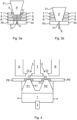
- Figures 3a and 3b illustrate open and closed positions, respectively, of a piston P of the arc quenching device 1, in this example a device 1 with only one piston P.
- the piston P is in its open position, and the device 1 is in an open state
- the piston is in its closed position, and the device 1 is in a closed state, where the lateral surface 21 of the piston P is in electrical contact with all the three phases T, S and R, short-circuiting all the phases to each other.
- the single piston P is arranged to axially move through respective axially aligned holes 6 through each of the three busbars T, S and R forming three layers of busbars. It follows that, in its closed position, the piston P is in physical (and thus electrical) contact with each of the first, second and third busbars T, S and R. Specifically, the lateral surface 21 of the piston P is in physical contact with the inside surface of the hole 6 through the first busbar T, with the inside surface of the hole 6 through the second busbar S and with the inside surface of the hole 6 through the third busbar R.
- the device 1 is arranged such that, after the axial movement of the piston P, the lateral surface 21 of the piston contacts respective inner surfaces of a hole 6 in the first busbar T, a hole 6 in the second busbar S, and a hole 6 in the third busbar R.
- the piston P may be provided with a guide 8 of an electrically insulating material, to aid the piston to pass through the openings 6.
- a guide 8 of an electrically insulating material, to aid the piston to pass through the openings 6.
- the guide 8 may then ensure that the piston makes physical and electrical contact with all the busbars it is arranged to contact at its closed position at the same time. If a piston P contacts only two busbars, e.g. T and S in figures 3 , there is a risk that the piston is delayed or prevented from making contact with all the busbars it is arranged to contact at its closed position, e.g. by welding taking place to the two first contacted busbars.
- the guide 8 of the piston may be arranged to pass through a guide hole 51 in an insulator 50 of an electrically insulating material, arranged on the other side of the openings 6 as seen in the direction of the axial movement of the piston.
- the front end of the guide 8 may extend into its guide hole 51 of the insulator 50 when the piston is in its open position, and may then then pass further into or through the guide hole during the axial movement until the piston has reached its closed position.
- the piston may be prevented from moving at an angle to the longitudinal axis 2o, or from tilting, during its axial movement.
- a Protective Earth (PE) busbar may be added as a forth layer of busbars.
- the PE busbar may then similarly have a through hole 6 which is axially aligned with the holes 6 of the phase busbars T, S and R, such that the lateral surface 21 of the piston P makes electrical contact also with an inner surface of the hole 6 through the PE busbar when it is in its closed position.
- a PE busbar may be used, or not, with any of the embodiments of the device 1, depending on whether it is desired to short-circuit the phases L1, L2 and L3 also to ground.
- the arc quenching device 1 may further comprise a protective earth busbar PE arranged such that, when the pyrotechnical actuator 3 is fired, each of the at least one piston P is axially moved until each of the at least one piston contacts the protective earth busbar such that each of the first, second and third busbars T, S and R are also short-circuited to the protective earth busbar via the at least one piston.
- a protective earth busbar PE arranged such that, when the pyrotechnical actuator 3 is fired, each of the at least one piston P is axially moved until each of the at least one piston contacts the protective earth busbar such that each of the first, second and third busbars T, S and R are also short-circuited to the protective earth busbar via the at least one piston.
- Figure 4 illustrates an example of an embodiment where the at least one piston consists of two pistons, a first piston P1 and a second piston P2 and the actuator 3 is used to enable axial movement of both pistons P1 and P2.
- the first and second pistons P1 and P2 are rigidly mechanically connected to each other and are arranged to axially move together (upwards in the figure) driven by the single actuator 3 to contact the first, second and third busbars T, S and R via end surfaces 22 thereof, optionally through first and second through holes 6 of a PE busbar.
- the end surfaces 22, as well as the through holes 6, may be as discussed herein.
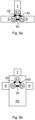
- Figure 5a illustrates an embodiment, seen from above, in which a single piston P is able to short-circuit all the three phases via respective end surfaces 22 of the busbars T, S and R.
- the tapered shape of the piston P enables the lateral surface 21 thereof to come into contact with the end surfaces 22 of the stationary busbars by means of the axial movement of the piston.
- Figure 5b shows the same embodiments as in figure 5a , but from the side and with the first busbar T hidden behind the piston P.
- Figure 5c illustrates an embodiment which is similar to the embodiment of figures 5a and 5b but with also a PE busbar.
- the PE busbar may be arranged as a second layer of busbars, which a hole 6 in the PE busbar axially aligned with the opening 6 formed between the end surfaces 22 of the phase busbars T, S and R.
- the PE busbar could be arranged in the same plane as the phase busbars, with an end surface 22 of the PE busbar at the opening 6 formed between the end surfaces 22 of the phase busbars such that also the end surface 22 of the PE busbar is in electrical contact with the lateral surface 21 of the piston P in its closed position.
- the device 1 is arranged such that, after the axial movement of the piston P, the lateral surface 21 of the piston contacts respective end surfaces 22 of the first busbar T, the second busbar S, and the third busbar R, and optionally of a PE busbar.
- Figures 6a and 6b illustrate embodiments in which the at least one piston P consists of three pistons, a first piston P1, an second piston P2 and a third piston P3, corresponding to one piston per phase.
- Figure 6a illustrates an embodiment without a PE busbar, where each of the three pistons is arranged to contact only one respective of the three phase busbars T, S and R, e.g. via a through hole or blind hole 6 in the busbar, when the pistons are in their closed positions. The phases are then short-circuited to each other via the electrical connections 60 between the pistons.
- Figure 6b illustrates a similar embodiment as figure 6a but with also a PE busbar.
- the PE busbar is arranged as a separate layer and having a respective through hole 6 for each of the three pistons P1, P2 and P3.
- its through hole in the PE busbar is axially aligned with through hole or blind hole 6 in the phase busbar it is arranged to contact.
- each piston is in electrical contact with both a respective one of the phase busbars and with the PE busbar.
- only one or two of the three pistons may be arranged to electrically contact the PE busbar when in its closed position. Then, all phases would still be short-circuited to ground via the electrical connection 60 between the pistons, but possibly not as well.
Landscapes
- Circuit Breakers (AREA)
Claims (12)
- Lichtbogenlöschvorrichtung (1) für eine elektrische Dreiphasenschaltanlage (10), wobei die Vorrichtung Folgendes umfasst:eine erste Sammelschiene (T), eine zweite Sammelschiene (S) und eine dritte Sammelschiene (R) jeweils einer jeweiligen Phase (L2, L3, L1) der Dreiphasenschaltanlage;mindestens einen Kolben (P) eines elektrisch leitenden Materials, der eine sich verjüngende Form aufweist, die sich zu ihrem vorderen Ende (23) verjüngt; undlediglich einen pyrotechnischen Aktor (3), der ausgelegt ist, dann, wenn der pyrotechnische Aktor gezündet wird, jeden des mindestens einen Kolbens (P) axial zu bewegen, bis alle der ersten, der zweiten und der dritten Sammelschiene (T, S, R) mittels des mindestens einen Kolbens miteinander kurzgeschlossen sind;wobei die Vorrichtung (1) ferner gekennzeichnet ist durch eine Schutzerdungssammelschiene (PE), die derart ausgelegt ist, dass dann, wenn der pyrotechnische Aktor (3) gezündet wird, jeder des mindestens einen Kolbens (P) axial bewegt wird, bis jeder des mindestens einen Kolbens die Schutzerdungssammelschiene derart kontaktiert, dass jede der ersten, der zweiten und der dritten Sammelschiene (T, S, R) auch mittels des mindestens einen Kolbens zur Schutzerdungssammelschiene kurzgeschlossen ist.
- Vorrichtung nach Anspruch 1, wobei der mindestens eine Kolben (P) aus lediglich einem Kolben besteht.
- Vorrichtung nach Anspruch 2, wobei die Vorrichtung (1) derart ausgelegt ist, dass nach der Axialbewegung des Kolbens (P) eine Seitenoberfläche (21) des Kolbens jeweilige Innenoberflächen eines Lochs (6) in der ersten Sammelschiene (T), eines Lochs (6) in der zweiten Sammelschiene (S) und eines Lochs (6) in der dritten Sammelschiene (R) kontaktiert.
- Vorrichtung nach Anspruch 2, wobei die Vorrichtung (1) derart ausgelegt ist, dass nach der Axialbewegung des Kolbens (P) eine Seitenoberfläche (21) des Kolbens jeweilige Stirnoberflächen (22) der ersten Sammelschiene (T), der zweiten Sammelschiene (S) und der dritten Sammelschiene (R) kontaktiert.
- Vorrichtung nach Anspruch 4, wobei jede der Stirnoberflächen (22) der ersten, der zweiten und der dritten Sammelschiene (T, S, R) gekrümmt ist, um gegen die Seitenoberfläche (21) des Kolbens (P), zu dessen Kontaktierung sie ausgelegt ist, formschlüssig zu sein.
- Vorrichtung nach Anspruch 1, wobei der mindestens eine Kolben (P) mehrere Kolben (P1, P2, P3) umfasst, die alle starr mechanisch miteinander verbunden sind, derart, dass sie sich in Bezug aufeinander nicht bewegen, wenn sie durch den Aktor (3) axial bewegt werden.
- Vorrichtung nach Anspruch 6, wobei alle Kolben (P) elektrisch miteinander verbunden sind, derart, dass die erste, die zweite und die dritte Sammelschiene (T, S, R) nach der Axialbewegung der Kolben mittels der elektrischen Verbindung (60) miteinander kurzgeschlossen sind.
- Vorrichtung nach einem vorhergehenden Anspruch, wobei die sich verjüngende Form eine Kegelform, z. B. eine Kegelstumpfform, ist.
- Vorrichtung nach einem vorhergehenden Anspruch, wobei jeder des mindestens einen Kolbens (P) mit einer Führung (8) aus einem elektrisch isolierenden Material versehen ist, die sich vom vorderen Ende (23) des Kolbens axial erstreckt.
- Vorrichtung nach einem vorhergehenden Anspruch, wobei die sich verjüngende Form sich mit einem Winkel (θ) zur Längsachse (20) im Bereich von 3-12°, bevorzugt 4-8°, z. B. 5,5-6,5°, verjüngt.
- Elektrische Dreiphasenschaltanlage (10), die die Vorrichtung (1) nach einem vorhergehenden Anspruch und einen Fehlerbeseitigungstrennschalter (11), der ausgelegt ist, einen Strom jeder der drei Phasen (L1, L2, L3), mit denen die erste, die zweite bzw. die dritte Sammelschiene (T, S, R) verbunden ist, zu unterbrechen, umfasst.
- Schaltanlage nach Anspruch 11, die für Nieder- oder Mittelspannungsanwendungen, bevorzugt Niederspannungsanwendungen, ausgelegt ist.
Priority Applications (3)
| Application Number | Priority Date | Filing Date | Title |
|---|---|---|---|
| EP21215585.7A EP4199023B1 (de) | 2021-12-17 | 2021-12-17 | Mit einem aktuator betriebene drehstromlichtbogenlöschvorrichtung |
| CN202211574689.XA CN116266509B (zh) | 2021-12-17 | 2022-12-08 | 一个致动器所操作的三相灭弧设备 |
| US18/064,567 US12170180B2 (en) | 2021-12-17 | 2022-12-12 | Three-phase arc quenching device operated by one actuator |
Applications Claiming Priority (1)
| Application Number | Priority Date | Filing Date | Title |
|---|---|---|---|
| EP21215585.7A EP4199023B1 (de) | 2021-12-17 | 2021-12-17 | Mit einem aktuator betriebene drehstromlichtbogenlöschvorrichtung |
Publications (2)
| Publication Number | Publication Date |
|---|---|
| EP4199023A1 EP4199023A1 (de) | 2023-06-21 |
| EP4199023B1 true EP4199023B1 (de) | 2025-03-19 |
Family
ID=78957140
Family Applications (1)
| Application Number | Title | Priority Date | Filing Date |
|---|---|---|---|
| EP21215585.7A Active EP4199023B1 (de) | 2021-12-17 | 2021-12-17 | Mit einem aktuator betriebene drehstromlichtbogenlöschvorrichtung |
Country Status (3)
| Country | Link |
|---|---|
| US (1) | US12170180B2 (de) |
| EP (1) | EP4199023B1 (de) |
| CN (1) | CN116266509B (de) |
Families Citing this family (2)
| Publication number | Priority date | Publication date | Assignee | Title |
|---|---|---|---|---|
| EP4542610A1 (de) * | 2023-10-16 | 2025-04-23 | Miba eMobility GmbH | Elektrische notfall-schaltvorrichtung mit einem verbindungselement zum herstellen einer elektrisch leitenden verbindung |
| DE102023211915A1 (de) * | 2023-11-29 | 2025-06-05 | Zf Friedrichshafen Ag | Stromrichter mit einem pyrotechnischen Aktuator zum Realisieren eines Kurzschlusses zwischen AC-Stromschienen eines Stromrichters |
Citations (1)
| Publication number | Priority date | Publication date | Assignee | Title |
|---|---|---|---|---|
| DE102011113955A1 (de) * | 2011-09-20 | 2012-03-29 | Daimler Ag | Elektrischer Schalter |
Family Cites Families (14)
| Publication number | Priority date | Publication date | Assignee | Title |
|---|---|---|---|---|
| SE9404455L (sv) | 1994-12-22 | 1996-06-23 | Asea Brown Boveri | Elektrisk kopplingsapparat |
| DE19712387B4 (de) | 1996-04-27 | 2005-12-08 | Delphi Technologies, Inc., Troy | Pyrotechnisches Schaltelement für elektrische Stromkreise |
| DE10254497B3 (de) * | 2002-11-22 | 2004-06-03 | Moeller Gmbh | Kurzschließer für eine Störlichtbogen-Schutzvorrichtung |
| FR2953322B1 (fr) | 2009-11-27 | 2013-02-15 | Snpe Materiaux Energetiques | Interrupteur electrique formant coupe-circuit a actionnement rapide |
| FR2980301B1 (fr) * | 2011-09-21 | 2014-06-20 | Schneider Electric Ind Sas | Court-circuiteur electrique a actionneur pyrotechnique |
| FR2992770B1 (fr) * | 2012-06-29 | 2014-08-01 | Herakles | Interrupteur electrique formant coupe-circuit a actionnement rapide |
| WO2014048495A1 (en) * | 2012-09-28 | 2014-04-03 | Autoliv Development Ab | Electrical pyrotechnic switch |
| CN103151189B (zh) * | 2013-02-04 | 2016-04-13 | 中国人民解放军海军工程大学 | 电磁斥力驱动活塞式高速开断器 |
| CN106489231B (zh) | 2014-07-16 | 2018-07-24 | Abb瑞士股份有限公司 | 用于在功率传输系统中使用的开关组件 |
| DE102014110825A1 (de) | 2014-07-30 | 2014-09-18 | Peter Lell | Elektrischer Schalter, insbesondere für hohe Spannungen und/oder hohe Ströme |
| US10153120B1 (en) | 2015-04-24 | 2018-12-11 | Abb Schweiz Ag | Bypass switch comprising a movable member with a first conductive section and a second conductive section |
| CN105869953B (zh) * | 2016-05-04 | 2018-10-23 | 中国船舶重工集团公司第七一〇研究所 | 应用于低压、中压或高压短路灭弧的开关装置 |
| FR3075460B1 (fr) * | 2017-12-14 | 2020-01-10 | Schneider Electric Industries Sas | Appareil de protection electrique comportant un systeme d'actionnement pyrotechnique |
| EP3696842A1 (de) | 2019-02-13 | 2020-08-19 | ABB Schweiz AG | Einschalter und schaltanlage |
-
2021
- 2021-12-17 EP EP21215585.7A patent/EP4199023B1/de active Active
-
2022
- 2022-12-08 CN CN202211574689.XA patent/CN116266509B/zh active Active
- 2022-12-12 US US18/064,567 patent/US12170180B2/en active Active
Patent Citations (1)
| Publication number | Priority date | Publication date | Assignee | Title |
|---|---|---|---|---|
| DE102011113955A1 (de) * | 2011-09-20 | 2012-03-29 | Daimler Ag | Elektrischer Schalter |
Also Published As
| Publication number | Publication date |
|---|---|
| CN116266509B (zh) | 2025-08-05 |
| EP4199023A1 (de) | 2023-06-21 |
| CN116266509A (zh) | 2023-06-20 |
| US12170180B2 (en) | 2024-12-17 |
| US20230197381A1 (en) | 2023-06-22 |
Similar Documents
| Publication | Publication Date | Title |
|---|---|---|
| EP2034503B1 (de) | Nieder-, Mittel- oder Hochspannungsschaltanlage mit Kurzschliesser. | |
| CN101454859B (zh) | 短路开关装置 | |
| US8319136B2 (en) | Arcing fault and arc flash protection system having a high-speed switch | |
| US12170180B2 (en) | Three-phase arc quenching device operated by one actuator | |
| EP3924991B1 (de) | Einschalter und schaltanlage | |
| US8618435B2 (en) | Ablative plasma gun | |
| WO2016154266A1 (en) | Arc flash mitigation switch for quenching external arc faults in low voltage switchgear | |
| US20110163070A1 (en) | Low-voltage, medium-voltage or high-voltage assembly | |
| US10937613B2 (en) | Triggered gap switching device | |
| EP2347485B1 (de) | Schaltinstallation mit bogenschutz und bogenschutzverfahren | |
| AU2017290406A1 (en) | Short-circuiting device for use in low-voltage and medium-voltage systems for protecting parts and personnel | |
| EP4199022B1 (de) | Dreiphasige lichtbogenlöschvorrichtung mit zwei kolben | |
| CN113826181A (zh) | 优化的三位开关 | |
| US3764944A (en) | Spiral motor coil | |
| KR20230130430A (ko) | 고속 투입 스위치와 이의 제어 방법 | |
| EP4718491A1 (de) | Trennschalter für einen hochspannungsgleichstromschutzschalter | |
| RU2091894C1 (ru) | Взрывной размыкатель | |
| HK1133950B (en) | Short circuit switching device | |
| PL203035B1 (pl) | Sposób eliminacji łuku elektrycznego i układ do eliminacji łuku elektrycznego |
Legal Events
| Date | Code | Title | Description |
|---|---|---|---|
| PUAI | Public reference made under article 153(3) epc to a published international application that has entered the european phase |
Free format text: ORIGINAL CODE: 0009012 |
|
| STAA | Information on the status of an ep patent application or granted ep patent |
Free format text: STATUS: THE APPLICATION HAS BEEN PUBLISHED |
|
| AK | Designated contracting states |
Kind code of ref document: A1 Designated state(s): AL AT BE BG CH CY CZ DE DK EE ES FI FR GB GR HR HU IE IS IT LI LT LU LV MC MK MT NL NO PL PT RO RS SE SI SK SM TR |
|
| STAA | Information on the status of an ep patent application or granted ep patent |
Free format text: STATUS: REQUEST FOR EXAMINATION WAS MADE |
|
| 17P | Request for examination filed |
Effective date: 20230828 |
|
| RBV | Designated contracting states (corrected) |
Designated state(s): AL AT BE BG CH CY CZ DE DK EE ES FI FR GB GR HR HU IE IS IT LI LT LU LV MC MK MT NL NO PL PT RO RS SE SI SK SM TR |
|
| STAA | Information on the status of an ep patent application or granted ep patent |
Free format text: STATUS: EXAMINATION IS IN PROGRESS |
|
| 17Q | First examination report despatched |
Effective date: 20240319 |
|
| GRAP | Despatch of communication of intention to grant a patent |
Free format text: ORIGINAL CODE: EPIDOSNIGR1 |
|
| STAA | Information on the status of an ep patent application or granted ep patent |
Free format text: STATUS: GRANT OF PATENT IS INTENDED |
|
| INTG | Intention to grant announced |
Effective date: 20241016 |
|
| GRAS | Grant fee paid |
Free format text: ORIGINAL CODE: EPIDOSNIGR3 |
|
| GRAA | (expected) grant |
Free format text: ORIGINAL CODE: 0009210 |
|
| STAA | Information on the status of an ep patent application or granted ep patent |
Free format text: STATUS: THE PATENT HAS BEEN GRANTED |
|
| AK | Designated contracting states |
Kind code of ref document: B1 Designated state(s): AL AT BE BG CH CY CZ DE DK EE ES FI FR GB GR HR HU IE IS IT LI LT LU LV MC MK MT NL NO PL PT RO RS SE SI SK SM TR |
|
| REG | Reference to a national code |
Ref country code: GB Ref legal event code: FG4D |
|
| REG | Reference to a national code |
Ref country code: CH Ref legal event code: EP |
|
| REG | Reference to a national code |
Ref country code: DE Ref legal event code: R096 Ref document number: 602021027765 Country of ref document: DE |
|
| REG | Reference to a national code |
Ref country code: IE Ref legal event code: FG4D |
|
| PG25 | Lapsed in a contracting state [announced via postgrant information from national office to epo] |
Ref country code: RS Free format text: LAPSE BECAUSE OF FAILURE TO SUBMIT A TRANSLATION OF THE DESCRIPTION OR TO PAY THE FEE WITHIN THE PRESCRIBED TIME-LIMIT Effective date: 20250619 |
|
| PG25 | Lapsed in a contracting state [announced via postgrant information from national office to epo] |
Ref country code: FI Free format text: LAPSE BECAUSE OF FAILURE TO SUBMIT A TRANSLATION OF THE DESCRIPTION OR TO PAY THE FEE WITHIN THE PRESCRIBED TIME-LIMIT Effective date: 20250319 |
|
| REG | Reference to a national code |
Ref country code: LT Ref legal event code: MG9D |
|
| PG25 | Lapsed in a contracting state [announced via postgrant information from national office to epo] |
Ref country code: NO Free format text: LAPSE BECAUSE OF FAILURE TO SUBMIT A TRANSLATION OF THE DESCRIPTION OR TO PAY THE FEE WITHIN THE PRESCRIBED TIME-LIMIT Effective date: 20250619 |
|
| PG25 | Lapsed in a contracting state [announced via postgrant information from national office to epo] |
Ref country code: HR Free format text: LAPSE BECAUSE OF FAILURE TO SUBMIT A TRANSLATION OF THE DESCRIPTION OR TO PAY THE FEE WITHIN THE PRESCRIBED TIME-LIMIT Effective date: 20250319 |
|
| PG25 | Lapsed in a contracting state [announced via postgrant information from national office to epo] |
Ref country code: LV Free format text: LAPSE BECAUSE OF FAILURE TO SUBMIT A TRANSLATION OF THE DESCRIPTION OR TO PAY THE FEE WITHIN THE PRESCRIBED TIME-LIMIT Effective date: 20250319 |
|
| PG25 | Lapsed in a contracting state [announced via postgrant information from national office to epo] |
Ref country code: BG Free format text: LAPSE BECAUSE OF FAILURE TO SUBMIT A TRANSLATION OF THE DESCRIPTION OR TO PAY THE FEE WITHIN THE PRESCRIBED TIME-LIMIT Effective date: 20250319 Ref country code: GR Free format text: LAPSE BECAUSE OF FAILURE TO SUBMIT A TRANSLATION OF THE DESCRIPTION OR TO PAY THE FEE WITHIN THE PRESCRIBED TIME-LIMIT Effective date: 20250620 |
|
| REG | Reference to a national code |
Ref country code: NL Ref legal event code: MP Effective date: 20250319 |
|
| REG | Reference to a national code |
Ref country code: AT Ref legal event code: MK05 Ref document number: 1777700 Country of ref document: AT Kind code of ref document: T Effective date: 20250319 |
|
| PG25 | Lapsed in a contracting state [announced via postgrant information from national office to epo] |
Ref country code: NL Free format text: LAPSE BECAUSE OF FAILURE TO SUBMIT A TRANSLATION OF THE DESCRIPTION OR TO PAY THE FEE WITHIN THE PRESCRIBED TIME-LIMIT Effective date: 20250319 |
|
| PG25 | Lapsed in a contracting state [announced via postgrant information from national office to epo] |
Ref country code: SE Free format text: LAPSE BECAUSE OF FAILURE TO SUBMIT A TRANSLATION OF THE DESCRIPTION OR TO PAY THE FEE WITHIN THE PRESCRIBED TIME-LIMIT Effective date: 20250319 |
|
| PG25 | Lapsed in a contracting state [announced via postgrant information from national office to epo] |
Ref country code: SM Free format text: LAPSE BECAUSE OF FAILURE TO SUBMIT A TRANSLATION OF THE DESCRIPTION OR TO PAY THE FEE WITHIN THE PRESCRIBED TIME-LIMIT Effective date: 20250319 |
|
| PG25 | Lapsed in a contracting state [announced via postgrant information from national office to epo] |
Ref country code: ES Free format text: LAPSE BECAUSE OF FAILURE TO SUBMIT A TRANSLATION OF THE DESCRIPTION OR TO PAY THE FEE WITHIN THE PRESCRIBED TIME-LIMIT Effective date: 20250319 Ref country code: PT Free format text: LAPSE BECAUSE OF FAILURE TO SUBMIT A TRANSLATION OF THE DESCRIPTION OR TO PAY THE FEE WITHIN THE PRESCRIBED TIME-LIMIT Effective date: 20250721 |
|
| PG25 | Lapsed in a contracting state [announced via postgrant information from national office to epo] |
Ref country code: PL Free format text: LAPSE BECAUSE OF FAILURE TO SUBMIT A TRANSLATION OF THE DESCRIPTION OR TO PAY THE FEE WITHIN THE PRESCRIBED TIME-LIMIT Effective date: 20250319 |
|
| PG25 | Lapsed in a contracting state [announced via postgrant information from national office to epo] |
Ref country code: AT Free format text: LAPSE BECAUSE OF FAILURE TO SUBMIT A TRANSLATION OF THE DESCRIPTION OR TO PAY THE FEE WITHIN THE PRESCRIBED TIME-LIMIT Effective date: 20250319 |
|
| PG25 | Lapsed in a contracting state [announced via postgrant information from national office to epo] |
Ref country code: CZ Free format text: LAPSE BECAUSE OF FAILURE TO SUBMIT A TRANSLATION OF THE DESCRIPTION OR TO PAY THE FEE WITHIN THE PRESCRIBED TIME-LIMIT Effective date: 20250319 Ref country code: EE Free format text: LAPSE BECAUSE OF FAILURE TO SUBMIT A TRANSLATION OF THE DESCRIPTION OR TO PAY THE FEE WITHIN THE PRESCRIBED TIME-LIMIT Effective date: 20250319 |
|
| PG25 | Lapsed in a contracting state [announced via postgrant information from national office to epo] |
Ref country code: RO Free format text: LAPSE BECAUSE OF FAILURE TO SUBMIT A TRANSLATION OF THE DESCRIPTION OR TO PAY THE FEE WITHIN THE PRESCRIBED TIME-LIMIT Effective date: 20250319 |
|
| PG25 | Lapsed in a contracting state [announced via postgrant information from national office to epo] |
Ref country code: SK Free format text: LAPSE BECAUSE OF FAILURE TO SUBMIT A TRANSLATION OF THE DESCRIPTION OR TO PAY THE FEE WITHIN THE PRESCRIBED TIME-LIMIT Effective date: 20250319 |
|
| PG25 | Lapsed in a contracting state [announced via postgrant information from national office to epo] |
Ref country code: IS Free format text: LAPSE BECAUSE OF FAILURE TO SUBMIT A TRANSLATION OF THE DESCRIPTION OR TO PAY THE FEE WITHIN THE PRESCRIBED TIME-LIMIT Effective date: 20250719 |
|
| REG | Reference to a national code |
Ref country code: DE Ref legal event code: R097 Ref document number: 602021027765 Country of ref document: DE |
|
| PGFP | Annual fee paid to national office [announced via postgrant information from national office to epo] |
Ref country code: DE Payment date: 20251211 Year of fee payment: 5 |
|
| PG25 | Lapsed in a contracting state [announced via postgrant information from national office to epo] |
Ref country code: DK Free format text: LAPSE BECAUSE OF FAILURE TO SUBMIT A TRANSLATION OF THE DESCRIPTION OR TO PAY THE FEE WITHIN THE PRESCRIBED TIME-LIMIT Effective date: 20250319 |
|
| PGFP | Annual fee paid to national office [announced via postgrant information from national office to epo] |
Ref country code: IT Payment date: 20251223 Year of fee payment: 5 |
|
| PLBE | No opposition filed within time limit |
Free format text: ORIGINAL CODE: 0009261 |
|
| STAA | Information on the status of an ep patent application or granted ep patent |
Free format text: STATUS: NO OPPOSITION FILED WITHIN TIME LIMIT |
|
| REG | Reference to a national code |
Ref country code: CH Ref legal event code: L10 Free format text: ST27 STATUS EVENT CODE: U-0-0-L10-L00 (AS PROVIDED BY THE NATIONAL OFFICE) Effective date: 20260128 |
|
| 26N | No opposition filed |
Effective date: 20251222 |
|
| PG25 | Lapsed in a contracting state [announced via postgrant information from national office to epo] |
Ref country code: LT Free format text: LAPSE BECAUSE OF FAILURE TO SUBMIT A TRANSLATION OF THE DESCRIPTION OR TO PAY THE FEE WITHIN THE PRESCRIBED TIME-LIMIT Effective date: 20250319 |
|
| PG25 | Lapsed in a contracting state [announced via postgrant information from national office to epo] |
Ref country code: MC Free format text: LAPSE BECAUSE OF FAILURE TO SUBMIT A TRANSLATION OF THE DESCRIPTION OR TO PAY THE FEE WITHIN THE PRESCRIBED TIME-LIMIT Effective date: 20250319 |
|
| REG | Reference to a national code |
Ref country code: CH Ref legal event code: H13 Free format text: ST27 STATUS EVENT CODE: U-0-0-H10-H13 (AS PROVIDED BY THE NATIONAL OFFICE) Effective date: 20260723 |