EP4199085B1 - Structure semi-conductrice et son procédé de fabrication - Google Patents
Structure semi-conductrice et son procédé de fabrication Download PDFInfo
- Publication number
- EP4199085B1 EP4199085B1 EP22865907.4A EP22865907A EP4199085B1 EP 4199085 B1 EP4199085 B1 EP 4199085B1 EP 22865907 A EP22865907 A EP 22865907A EP 4199085 B1 EP4199085 B1 EP 4199085B1
- Authority
- EP
- European Patent Office
- Prior art keywords
- layer
- substrate
- initial
- contact
- dielectric layer
- Prior art date
- Legal status (The legal status is an assumption and is not a legal conclusion. Google has not performed a legal analysis and makes no representation as to the accuracy of the status listed.)
- Active
Links
Images


Classifications
-
- H—ELECTRICITY
- H10—SEMICONDUCTOR DEVICES; ELECTRIC SOLID-STATE DEVICES NOT OTHERWISE PROVIDED FOR
- H10B—ELECTRONIC MEMORY DEVICES
- H10B12/00—Dynamic random access memory [DRAM] devices
- H10B12/30—DRAM devices comprising one-transistor - one-capacitor [1T-1C] memory cells
-
- H—ELECTRICITY
- H10—SEMICONDUCTOR DEVICES; ELECTRIC SOLID-STATE DEVICES NOT OTHERWISE PROVIDED FOR
- H10B—ELECTRONIC MEMORY DEVICES
- H10B12/00—Dynamic random access memory [DRAM] devices
- H10B12/01—Manufacture or treatment
- H10B12/02—Manufacture or treatment for one transistor one-capacitor [1T-1C] memory cells
- H10B12/05—Making the transistor
-
- H—ELECTRICITY
- H10—SEMICONDUCTOR DEVICES; ELECTRIC SOLID-STATE DEVICES NOT OTHERWISE PROVIDED FOR
- H10B—ELECTRONIC MEMORY DEVICES
- H10B12/00—Dynamic random access memory [DRAM] devices
- H10B12/30—DRAM devices comprising one-transistor - one-capacitor [1T-1C] memory cells
- H10B12/31—DRAM devices comprising one-transistor - one-capacitor [1T-1C] memory cells having a storage electrode stacked over the transistor
- H10B12/315—DRAM devices comprising one-transistor - one-capacitor [1T-1C] memory cells having a storage electrode stacked over the transistor with the capacitor higher than a bit line
-
- H—ELECTRICITY
- H10—SEMICONDUCTOR DEVICES; ELECTRIC SOLID-STATE DEVICES NOT OTHERWISE PROVIDED FOR
- H10B—ELECTRONIC MEMORY DEVICES
- H10B12/00—Dynamic random access memory [DRAM] devices
- H10B12/30—DRAM devices comprising one-transistor - one-capacitor [1T-1C] memory cells
- H10B12/48—Data lines or contacts therefor
- H10B12/482—Bit lines
-
- H—ELECTRICITY
- H10—SEMICONDUCTOR DEVICES; ELECTRIC SOLID-STATE DEVICES NOT OTHERWISE PROVIDED FOR
- H10B—ELECTRONIC MEMORY DEVICES
- H10B12/00—Dynamic random access memory [DRAM] devices
- H10B12/30—DRAM devices comprising one-transistor - one-capacitor [1T-1C] memory cells
- H10B12/48—Data lines or contacts therefor
- H10B12/488—Word lines
-
- H—ELECTRICITY
- H10—SEMICONDUCTOR DEVICES; ELECTRIC SOLID-STATE DEVICES NOT OTHERWISE PROVIDED FOR
- H10D—INORGANIC ELECTRIC SEMICONDUCTOR DEVICES
- H10D30/00—Field-effect transistors [FET]
- H10D30/60—Insulated-gate field-effect transistors [IGFET]
- H10D30/63—Vertical IGFETs
-
- H—ELECTRICITY
- H10—SEMICONDUCTOR DEVICES; ELECTRIC SOLID-STATE DEVICES NOT OTHERWISE PROVIDED FOR
- H10D—INORGANIC ELECTRIC SEMICONDUCTOR DEVICES
- H10D30/00—Field-effect transistors [FET]
- H10D30/60—Insulated-gate field-effect transistors [IGFET]
- H10D30/67—Thin-film transistors [TFT]
- H10D30/6728—Vertical TFTs
-
- H—ELECTRICITY
- H10—SEMICONDUCTOR DEVICES; ELECTRIC SOLID-STATE DEVICES NOT OTHERWISE PROVIDED FOR
- H10D—INORGANIC ELECTRIC SEMICONDUCTOR DEVICES
- H10D64/00—Electrodes of devices having potential barriers
- H10D64/60—Electrodes characterised by their materials
-
- H—ELECTRICITY
- H10—SEMICONDUCTOR DEVICES; ELECTRIC SOLID-STATE DEVICES NOT OTHERWISE PROVIDED FOR
- H10D—INORGANIC ELECTRIC SEMICONDUCTOR DEVICES
- H10D30/00—Field-effect transistors [FET]
- H10D30/60—Insulated-gate field-effect transistors [IGFET]
- H10D30/67—Thin-film transistors [TFT]
- H10D30/674—Thin-film transistors [TFT] characterised by the active materials
-
- H—ELECTRICITY
- H10—SEMICONDUCTOR DEVICES; ELECTRIC SOLID-STATE DEVICES NOT OTHERWISE PROVIDED FOR
- H10D—INORGANIC ELECTRIC SEMICONDUCTOR DEVICES
- H10D86/00—Integrated devices formed in or on insulating or conducting substrates, e.g. formed in silicon-on-insulator [SOI] substrates or on stainless steel or glass substrates
- H10D86/201—Integrated devices formed in or on insulating or conducting substrates, e.g. formed in silicon-on-insulator [SOI] substrates or on stainless steel or glass substrates the substrates comprising an insulating layer on a semiconductor body, e.g. SOI
Definitions
- the present application relates to the technical field of semiconductors, and in particular to a 1T-1C DRAM and a manufacturing method thereof.
- the semiconductor structure may include memory cells.
- the memory cell usually includes a transistor and a capacitor electrically connected to the transistor.
- the capacitor stores data information, and the transistor controls the reading and writing of data information in the capacitor.
- the gate of the transistor is electrically connected to a word line (WL), and the on and off of the transistor is controlled by the voltage on the WL.
- One of a source and a drain of the transistor is electrically connected to a bit line (BL), and the other of the source and the drain is electrically connected to the capacitor. Data information is stored or outputted by using the BL.
- the GAA transistor includes a first conductive layer, a channel region, and a second conductive layer that are stacked sequentially.
- One of the first conductive layer and the second conductive layer is a source, and the other is a drain.
- a dielectric layer surrounds the side surface of the channel region, and a gate is disposed on the dielectric layer.
- the foregoing transistor has a relatively large contact resistance with another structure (for example, a BL or a capacitor), the transistor requires a relatively large current, and the semiconductor structure has poor performance. Background may be found in US2018/197862A1 , US2021/050443A1 and US 2019/305085A1
- the embodiments of the present disclosure provide a manufacturing method of a1T-1C Dram.
- vertical transistors are formed, and at least one of a source and a drain in the vertical transistor is a semi-metal layer, to reduce a contact resistance between the vertical transistor and another structure, and a contact resistance inside the vertical transistor, thereby improving the performance of the semiconductor structure.
- an embodiment of the present application provides a manufacturing method of a semiconductor structure, including the following steps: step S101: Provide a substrate.
- a substrate 10 may be a semiconductor substrate.
- the substrate 10 may be a silicon substrate, a germanium substrate, a silicon germanium substrate, a gallium nitride substrate, a gallium arsenide substrate, a silicon-on-insulator (SOI) substrate, a germanium-on-insulator (GOI) substrate, or the like.
- the substrate 10 may be doped or not.
- the substrate 10 may be a N-type substrate or a P-type substrate.
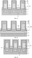
- a first cross section shown in FIG. 2 is a plane perpendicular to a second direction.
- a second cross section shown in FIG. 3 is a plane perpendicular to the second direction.
- a plurality of BLs 11 may be also disposed in the substrate 10, are spaced apart from each other, and extend along the second direction. As shown in FIG. 3 , the plurality of BLs 11 extend along a horizontal direction (a direction X shown in FIG. 3 ). As shown in FIG. 2 and FIG. 3 , the BLs 11 may be exposed on the surface of the substrate 10. The BLs 11 are exposed on the upper surface of the substrate 10, to be electrically connected to another structure on the substrate 10.
- a shallow trench isolation (STI) structure 12 is also disposed in the substrate 10.
- the STI structure 12 is disposed between adjacent BLs 11, to isolate them.
- the STI structure 12 may be filled with an insulating material such as silicon nitride or silicon oxide.
- Step S102 Form a plurality of laminated structures arranged at intervals on the substrate, where each of the laminated structures includes a first conductive layer, an insulating layer, and a second conductive layer that are stacked sequentially, and at least one of the first conductive layer and the second conductive layer is a semi-metal layer.
- the laminated structure 20 includes a first conductive layer 21, an insulating layer 22, and a second conductive layer 23.
- One of the first conductive layer 21 and the second conductive layer 23 is electrically connected to a capacitor, and the other of the first conductive layer 21 and the second conductive layer 23 is electrically connected to the BLs 11.
- the first conductive layer 21, the insulating layer 22, and the second conductive layer 23 are stacked sequentially in a vertical direction (a direction Z shown in FIG. 5 ).
- the first conductive layer 21 is electrically connected to BL 11, and the second conductive layer 23 is electrically connected to the capacitor.
- the insulating layer 22 may be an oxide layer.
- a material of the insulating layer 22 may be silicon oxide.
- At least one of the first conductive layer 21 and the second conductive layer 23 is a semi-metal layer.
- the first conductive layer 21 is a semi-metal layer
- the second conductive layer 23 is also a semi-metal layer.
- a material of the semi-metal layer is bismuth.
- the first conductive layer 21 and/or the second conductive layer 23 are/is disposed as a semi-metal layer, which can reduce a contact resistance between the laminated structure 20 and the BL 11 and/or a capacitor, thereby improving the performance of the semiconductor structure.
- At least one of laminated structures 20 is disposed on each of the BLs 11 along a second direction (a direction X shown in FIG. 5 ).
- the first conductive layer 21 is in contact with the BL 11, such that the first conductive layer 21 is electrically connected to the BL 11.
- the laminated structure 20 may be in a shape of a column, such as a cylinder, an elliptical column, a square column, or a rectangular column.
- the laminated structures 20 may be arranged in an array.
- a plurality of laminated structures 20 are arranged at intervals on the substrate 10, where the laminated structure 20 includes the first conductive layer 21, the insulating layer 22, and the second conductive layer 23 that are stacked sequentially, and at least one of the first conductive layer 21 and the second conductive layer 23 is a semi-metal layer, which includes following steps.
- the first conductive layer 21, the insulating layer 22, and the second conductive layer 23 that are stacked are formed through deposition on the substrate 10. As shown in FIG. 2 and FIG. 3 , the first conductive layer 21 is deposited on the substrate 10, the insulating layer 22 is deposited on the first conductive layer 21, and the second conductive layer 23 is deposited on the insulating layer 22.
- the deposition may be a chemical vapor deposition (CVD), a physical vapor deposition (PVD), or an atomic layer deposition (ALD).
- the first conductive layer 21, the insulating layer 22, and the second conductive layer 23 are etched, to form the plurality of laminated structures 20 arranged at intervals.
- a part of the first conductive layer 21, a part of the insulating layer 22, and a part of the second conductive layer 23 are removed through dry etching or wet etching, such that the retained first conductive layer 21, the retained insulating layer 22, the retained second conductive layer 23 are separated to form the plurality of laminated structures 20 that are spaced apart from each other.
- Step S103 Form a channel layer covering the laminated structures, and a dielectric layer covering the channel layer.
- the channel layer 30 covers the laminated structures 20.
- the dielectric layer 40 covers the channel layer 30.
- the channel layer 30 covers the side surfaces and the top surfaces of the laminated structures 20.
- the dielectric layer 40 covers the side surface and the top surface of the channel layer 30, where the top surface is away from the substrate 10.
- the channel layer 30 covers an outer peripheral surface of the first conductive layer 21, an outer peripheral surface of the insulating layer 22, and an outer peripheral surface of the second conductive layer 23.
- the channel layer 30 further covers the top surface 24 of the second conductive layer.
- One of the first conductive layer 21 and the second conductive layer 23 forms a source, and the other forms a drain.
- the channel layer 30 surrounding the side surface of the laminated structure 20 forms a channel region, to provide a conductive channel between the source and the drain, such that carriers can move from the source to the drain or vice versa.
- the dielectric layer 40 may be an oxide layer, and the dielectric layer 40 on the side surface of the channel layer 30 forms a gate oxide layer.
- the channel region is layered.
- a material of the channel layer 30 may include molybdenum sulfide, such as molybdenum disulfide, transition metal sulfur compounds (TMDs), or the like.
- molybdenum sulfide such as molybdenum disulfide, transition metal sulfur compounds (TMDs), or the like.
- TMDs transition metal sulfur compounds
- the layered molybdenum sulfide has a high specific surface area, which is beneficial to overcome the short channel effect.
- the on-off ratio refers to the ratio of the on-state current to the off-state current of a device. Specifically, in a transistor, when the source-drain voltage remains unchanged, the ratio of the source-drain current measured when the gate voltage is applied to that when the gate voltage is not applied is the on-off ratio.
- the material of the channel layer 30 is molybdenum sulfide.
- the material of the semi-metal layer is bismuth.
- the channel layer 30 is made of molybdenum sulfide.
- the first conductive layer 21 and the second conductive layer 23 are both made of bismuth.
- the energy barriers at the interfaces of molybdenum sulfide and bismuth are reduced, which can reduce the metal-induced gap states (MIGSs) between the channel layer 30 and the first conductive layer 21, and between the channel layer 30 and the second conductive layer 23, thereby reducing the contact resistances between the channel layer 30 and the first conductive layer 21 and between the channel layer 30 and the second conductive layer 23.
- MIGSs metal-induced gap states
- the channel layer 30 covering the laminated structures 20 and the dielectric layer 40 covering the channel layer 30 are formed in the following steps:
- the channel layer 30 is deposited on the laminated structure 20 and the substrate 10, and the channel layer 30 covers the top surfaces and the side surfaces of the laminated structures 20, and the top surface of the substrate 10.
- the channel layer 30 is formed through a deposition process.
- the channel layer 30 covers the top surfaces and the side surfaces of the laminated structures 20, and the top surface of the substrate 10.
- the dielectric layer 40 is deposited on the channel layer 30.
- the dielectric layer 40 is formed through a deposition process.
- the dielectric layer 40 covers the entire surface of the channel layer 30.
- Step S104 Form WLs extending along a first direction, where the WL includes a plurality of contact parts and a connecting part connecting adjacent contact parts, the contact part surrounds and is in contact with a side surface of the dielectric layer, and the contact part is opposite to at least a part of the insulating layer.
- the contact part 64 corresponds to a part of the insulating layer 22.
- the contact part 64 serves as a gate of the transistor, that is, a part of the WL 63 serves as a gate.
- the orthographic projection of the insulating layer 22 partially overlaps with that of the contact part 64.
- the top surface of the contact part 64 is lower than that of the insulating layer 22, and a bottom of the contact part 64 is higher than that of the insulating layer 22.
- the connecting part 65 connects two adjacent contact parts 64.
- the heights of the connecting part 65 and the contact part 64 may be same or not.
- the specific structure of the connecting part 65 may be determined according to a specific condition.
- the first conductive layer 21, the insulating layer 22, and the second conductive layer 23 are stacked sequentially to form the laminated structure 20.
- At least one of the first conductive layer 21 and the second conductive layer 23 is a semi-metal layer, which can not only reduce a contact resistance between a laminated structure 20 and another structure, but a contact resistance between the first conductive layer 21 and/or the second conductive layer 23 and the channel layer 30, thereby improving the performance of the semiconductor structure.
- the first conductive layer 21, the insulating layer 22, the second conductive layer 23, the channel layer 30, the dielectric layer 40, and the contact part 64 form a vertical transistor. Adjusting the height of the laminated structure 20 can increase the height of the channel layer 30, which facilitates improving the short-channel effects of the transistor, thereby improving the performance of the semiconductor structure.
- the manufacturing method further includes: filling a first support layer 50 between the laminated structures 20 covered by the channel layer 30 and the dielectric layer 40, where a surface of the first support layer 50 away from the substrate 10 is higher than that of the first conductive layer 21 away from substrate 10, and is lower than a surface of the insulating layer 22 away from the substrate 10.
- the first support layer 50 may be used as a cushion layer to increase the pitch between the WL 63 formed subsequently and the substrate 10, such that the bottom surface of the WL 63 is higher than the top surface of the first conductive layer 21, that is, the surface of the WL 63 facing the substrate 10 is higher than the surface of the first conductive layer 21 away from the substrate 10.
- the surface of the first support layer 50 away from the substrate 10 is lower than the surface of the insulating layer 22 away from the substrate 10, such that the bottom surface of the WL 63 is lower than the top surface of the first conductive layer 21, thereby ensuring that the WL 63 is opposite to the insulating layer 22.
- the material of the first support layer 50 may be silicon nitride or silicon oxynitride, and the first support layer 50 and the dielectric layer 40 have a relatively large selectivity.
- the selectivity of the first support layer 50 to the dielectric layer 40 is greater than 5, to avoid damaging the dielectric layer 40 when the first support layer 50 is etched, thereby reducing damage on the gate oxide layer in the transistor.
- the filling a first support layer 50 between the laminated structures 20 covered by the channel layer 30 and the dielectric layer 40, where a surface of the first support layer 50 away from the substrate 10 is higher than that of the first conductive layer 21 away from the substrate 10, and is lower than a surface of the insulating layer 22 away from the substrate 10 may include the following process: A first initial support layer 51 is formed on the dielectric layer 40, where the first initial support layer 51 is filled between the laminated structures 20 covered by the channel layer 30 and the dielectric layer 40, and the first initial support layer 51 covers a top surface of the dielectric layer 40. As shown in FIG. 12 and FIG.
- the first initial support layer 51 is formed through deposition and is filled between the laminated structures 20 covered by the channel layer 30 and the dielectric layer 40.
- the first initial support layer 51 further covers the top surface of the dielectric layer 40. Specifically, the upper surface of the first initial support layer 51 is higher than the upper surface of the dielectric layer 40.
- the retained first initial support layer 51 forms the first support layer 50.
- a part of the first initial support layer 51 is removed through dry etching or wet etching.
- the part of the first initial support layer 51 located between the laminated structures 20 covered by the channel layer 30 and the dielectric layer 40 is retained.
- the retained first initial support layer 51 forms the first support layer 50.
- the WLs 63 extending along the first direction are formed, where the WL 63 includes the plurality of contact parts 64 and the connecting part 65 connecting adjacent contact parts 64, the contact part 64 surrounds and is in contact with the side surface of the dielectric layer 40, and the contact part 64 is opposite to at least a part of the insulating layer 22, which may include the following steps: Step S1041: Form an initial WL layer covering the first support layer and the dielectric layer.
- the initial WL layer 61 is formed through a deposition process, and covers the first support layer 50 and the dielectric layer 40. As shown in FIG. 16 and FIG. 17 , the initial WL layer 61 covers the top surface of the first support layer 50, and covers the side surface and the top surface of the dielectric layer 40. There is also a gap in the initial WL layer 61 covering the side surfaces of the dielectric layer 40, that is, the initial WL layer 61 is not filled between the laminated structures 20 covered by the channel layer 30 and the dielectric layer 40.
- Step S1042 Remove a part of the initial WL layer located on the first support layer along the first direction, such that the initial WL layer is divided, to form a plurality of intermediate WL layers arranged at intervals.
- the part of the initial WL layer 61 located on the first support layer 50 is removed, such that the initial WL layer 61 is divided, to form the plurality of intermediate WL layers 62 arranged at intervals.
- the intermediate WL layers 62 extend along the first direction, that is, a part of the initial WL layer 61 on the first support layer 50 is removed along the first direction, the retained initial WL layer 61 forms the intermediate WL layers 62.
- the part of the initial WL layer 61 located on the first support layer 50 is removed along the first direction, such that the initial WL layer 61 forms the plurality of intermediate WL layers 62 arranged at intervals, which may further include the following process:
- a mask layer 71 covering the initial WL layer 61 is formed and is filled between the laminated structures 20 covered by the channel layer 30, the dielectric layer 40, and the initial WL layer 61.
- the mask layer 71 covers the top surface of the initial WL layer 61.
- the mask layer 71 is deposited on the initial WL layer 61.
- the mask layer 71 is filled between the laminated structures 20 covered by the channel layer 30, the dielectric layer 40, and the initial WL layer 61.
- the mask layer 71 further covers the top surface of the initial WL layer 61.
- the top surface of the mask layer 71 is higher than the top surface of the initial WL layer 61.
- a first photoresist layer 72 is formed thereon.
- the first photoresist layer 72 is provided with a trench 73 extending along the first direction, and orthographic projection of the trench 73 on the substrate 10 and that of the initial WL layer 61 on the side surface of the laminated structure 20 on the substrate 10 do not overlap.
- the first photoresist layer 72 is spin-coated on the mask layer 71.
- the first photoresist layer 72 is provided with a trench 73 running through the first photoresist layer 72.
- the trench 73 is staggered from the initial WL layer 61 on the side surface and the top surface of the dielectric layer 40, and is opposite to a part of the initial WL layer 61 on the first support layer 50.
- the mask layer 71 is etched by using the first photoresist layer 72 as a mask.
- the mask layer 71 is etched by using the first photoresist layer 72 as a mask.
- the pattern on the first photoresist layer 72 is transferred to the mask layer 71.
- the initial WL layer 61 is exposed from the pattern formed by the mask layer 71.
- the initial WL layer 61 is etched by using the etched mask layer 71 as a mask, to form the intermediate WL layers 62.
- a part of the initial WL layer 61 on the first support layer 50 is removed through anisotropic etching.
- the retained initial WL layer 61 forms intermediate WL layers 62. Gaps between a plurality of intermediate WL layers 62 expose the first support layer 50.
- Step S1043 Remove the intermediate WL layer on a top surface of the dielectric layer, and a part of the intermediate WL layer away from the substrate on the side surface of the dielectric layer, and taking the retained intermediate WL layers as the WLs.
- the intermediate WL layer 62 on a top surface of the dielectric layer 40 and a part of the intermediate WL layer 62 on the side surface of the dielectric layer 40 are removed through etching.
- the retained intermediate WL layers 62 form the WLs 63.
- the top surface of the WL 63 is lower than the top surface of the insulating layer 22, and the WL 63 is opposite to the insulating layer 22.
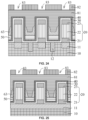
- the manufacturing method of the semiconductor structure further includes: forming a second support layer 81 covering the WLs 63, the first support layer 50, and the second support layer 50 on the dielectric layer 40. As shown in FIG. 24 and FIG. 25 , the second support layer 81 is deposited. The second support layer 81 covers the WLs 63, the first support layer 50, and the dielectric layer 40.
- the top surface of the second support layer 81 is higher than the top surface of the dielectric layer 40.
- the surface of the second support layer 81 away from the substrate 10 may be flat.
- the second support layer 81 is flattened, through, for example, chemical mechanical polishing (CMP), to make the top surface of the second support layer 81 flat.
- CMP chemical mechanical polishing
- the second support layer 81 and the first support layer 50 may be made of a same insulating material, such that the second support layer 81 is integrated with the first support layer 50.
- the second support layer 81 and the first support layer 50 cover and isolate the WLs 63 to insulate the WLs 63.
- the second photoresist layer 82 is formed on the second support layer 81.
- the second photoresist layer 82 is provided with a plurality of openings 83.
- the openings 83 are opposite to the laminated structures 20.
- the second photoresist layer 82 is formed on the second support layer 81.
- the second photoresist layer 82 is provided with a plurality of openings 83.
- the plurality of openings 83 correspond to the plurality of laminated structures 20 respectively, and the opening 83 is opposite to the laminated structure 20 corresponding thereto.
- Orthographic projection of the opening 83 on the substrate 10 is located within that of the laminated structure 20 corresponding thereto on the substrate 10, or the orthographic projection of the opening 83 on the substrate 10 overlaps with that of the laminated structure 20 corresponding thereto on the substrate 10.
- a shape of a cross section of the contact hole 84 may be an inverted trapezoid with a large top and a small bottom. As shown in FIG. 30 and FIG. 31 , the shape of the cross section of the contact hole 84 may be also a rectangle and a trapezoid that are connected to each other. The rectangle is disposed at one side of the trapezoid close to the substrate 10, and a bottom edge of the rectangle coincides with an upper bottom of the trapezoid.
- the third conductive layer 90 is formed in the contact hole 84, and the third conductive layer 90 is electrically connected to the second conductive layer. As shown in FIG. 32 and FIG. 33 , the third conductive layer 90 is deposited in the contact hole 84, and the third conductive layer 90 is in contact with the second conductive layer 23, such that the third conductive layer 90 is electrically connected to the second conductive layer 23.
- the third conductive layer 90 may be a capacitive contact pad, and a capacitor is formed on the third conductive layer 90.
- an embodiment of the present application further provides a semiconductor structure, including: laminated structures 20, a channel layer 30, a dielectric layer 40, and a gate.
- the laminated structures 20 are disposed on the substrate 10.
- the substrate 10 is configured to support the laminated structures 20.
- the substrate 10 may be a semiconductor substrate such as a silicon substrate.
- a plurality of BLs 11 may be also disposed in the substrate 10, are spaced apart from each other, and extend along the second direction (the direction X shown in FIG. 11 ).
- the BLs 11 may be exposed on the surface of the substrate 10, to be electrically connected to another structure on the substrate 10.
- An STI structure 12 may also be disposed between adjacent BLs 11, which are isolated by the STI structure structures 12.
- the plurality of laminated structures 20 are formed on the substrate 10, and are disposed at intervals.
- the laminated structure 20 includes a first conductive layer 21, an insulating layer 22, and a second conductive layer 23 that are stacked. As shown in FIG. 10 and FIG. 11 , along the direction away from the substrate 10, the first conductive layer 21, the insulating layer 22, and the second conductive layer 23 are disposed sequentially.
- One of the first conductive layer 21 and the second conductive layer 23 is a source
- the other of the first conductive layer 21 and the second conductive layer 23 is a drain.
- At least one of the source and the drain is a semi-metal layer.
- the material of the semi-metal layer may be bismuth, and the material of the insulating layer 22 may be silicon oxide. Disposing at least one of the source or the drain as a semi-metal layer can reduce the contact resistance between the laminated structure 20 and another structure (for example, the BL 11 and/or the capacitor), thereby improving the performance of the semiconductor structure
- the laminated structure 20 is disposed on each of the BLs 11, and one of the source and the drain in the laminated structure 20 is in contact with the BL 11, such that the source or drain is electrically connected to the BL 11.
- the laminated structure 20 may be in a shape of a column, such as a cylinder, an elliptical column, a square column, or a rectangular column.
- the laminated structures 20 may be arranged in an array.
- the channel layer 30 covers the side surface of the laminated structure 20.
- the channel layer 30 surrounding the side surface of the laminated structure 20 forms a channel region, to provide a conductive channel between the source and the drain, such that carriers can move from the source to the drain or vice versa.
- the channel region is layered.
- a material of the channel layer 30 may include molybdenum sulfide, such as molybdenum disulfide. There is a band gap in the layered molybdenum sulfide, which forms a field effect transistor with a high on-off ratio.
- the material of the channel layer 30 is molybdenum sulfide, and the materials of the source and the drain are both bismuth, to reduce the MIGSs and energy barriers between the channel layer 30 and the source, and between the channel layer 30 and the drain, thereby reducing the contact resistances between the channel layer 30 and the source and between the channel layer 30 and the drain.
- the dielectric layer 40 covers the side surface of the channel layer 30 and may be an oxide layer.
- the dielectric layer 40 located on the side surface of the channel layer 30 forms a gate oxide layer.
- the dielectric layer 40 is made of silicon oxide.
- a gate is annularly provided on the dielectric layer 40.
- the gate surrounds and is in contact with the side surface of the dielectric layer 40.
- the gate is opposite to at least a part of the insulating layer 22.
- the orthographic projection of the dielectric layer 40 at least partially overlaps with that of the gate.
- the top surface of the gate is lower than the top surface of the dielectric layer 40, and the bottom surface of the gate is higher than the bottom surface of the dielectric layer 40.
- the semiconductor structure in the embodiments of the present application further includes WLs 63.
- the WLs 63 extend along the first direction.
- the WL 63 includes contact parts 64 and a connecting part 65 connecting two adjacent contact parts 64.
- the contact part 64 is a gate disposed annularly on the dielectric layer 40, that is, a part of the WL 63 is a gate. It can be understood that, along the first direction, the connecting part 65 and the gate are arranged at intervals, and the connecting part 65 connects the plurality of gates in the first direction into one to form the WLs 63.
- the WL 63 is disposed on the first support layer 50.
- the first support layer 50 is located below the WL 63 and is filled between laminated structures 20 covered by the dielectric layer 40 and the channel layer 30, to elevate the WLs 63.
- the second support layer 81 may further cover the WLs 63, and the second support layer 81 and the first support layer 50 electrically isolate the WLs 63.
- the second support layer 81 and the first support layer 50 may be made of a same material, such that the second support layer 81 is integrated with the first support layer 50.
- the second support layer 81 also covers the dielectric layer 40.
- the second support layer 81 is provided with a contact hole running through the dielectric layer 40 and the channel layer 30, to expose the second conductive layer 23 in the laminated structures 20.
- the third conductive layer 90 fills the contact hole, and one end of the third conductive layer 90 is in contact with the second conductive layer 23, such that the third conductive layer 90 is electrically connected to the second conductive layer 23.
- the other end of the third conductive layer 90 may be connected to a capacitor.
- the first conductive layer 21, the insulating layer 22, and the second conductive layer 23 are stacked sequentially to form the laminated structure 20.
- One of the first conductive layer 21 and the second conductive layer 23 is the source and the other is the drain.
- At least one of the first conductive layer 21 and the second conductive layer 23 is a semi-metal layer, which can not only reduce a contact resistance between a laminated structure 20 and another structure, but a contact resistance between the first conductive layer 21 and/or the second conductive layer 23 and the channel layer 30, thereby improving the performance of the semiconductor structure.
- the channel layer 30 covers the side surface of the laminated structure 20.
- the dielectric layer 40 covers the side surface of the channel layer 30.
- a gate is annularly provided on the dielectric layer 40.
- the laminated structures 20, the channel layer 30, the dielectric layer 40, and the gate form a vertical transistor. Adjusting the height of the laminated structure 20 can increase the height of the channel layer 30, which facilitates improving the short-channel effects of the transistor, thereby improving the performance of the semiconductor structure.
Landscapes
- Engineering & Computer Science (AREA)
- Manufacturing & Machinery (AREA)
- Semiconductor Memories (AREA)
- Internal Circuitry In Semiconductor Integrated Circuit Devices (AREA)
Claims (12)
- Procédé de fabrication d'une DRAM 1T-1C, comprenant :la fourniture d'un substrat (10) (S101) ;la formation de plusieurs structures stratifiées (20) disposées à intervalles sur le substrat (10), dans lequel chacune des structures stratifiées (20) comprend une première couche conductrice (21), une couche isolante (22) et une deuxième couche conductrice (23) qui sont empilées successivement, et au moins l'une de la première couche conductrice (21) et de la deuxième couche conductrice (23) est du bismuth (S102) ;la formation d'une couche de canal (30) recouvrant les structures stratifiées (20) et d'une couche diélectrique (40) recouvrant la couche de canal (30) (S103) ; etla formation de lignes de mots (WL)(63) s'étendant le long d'une première direction (Y), dans lequel la WL (63) comprend une pluralité de parties de contact (64) et une partie de connexion (65) reliant des parties de contact (64) adjacentes, la partie de contact (64) entoure et est en contact avec une surface latérale de la couche diélectrique (40), et la partie de contact (64) est opposée à au moins une partie de la couche isolante (22) (S104).
- Procédé de fabrication d'une DRAM 1T-1C selon la revendication 1, dans lequel un matériau de la couche de canal (30) comprend du sulfure de molybdène.
- Procédé de fabrication d'une DRAM 1T-1C selon la revendication 1, dans lequel la formation d'une couche de canal (30) recouvrant les structures stratifiées (20), et d'une couche diélectrique (40) recouvrant la couche de canal (30) (S103) comprend :le dépôt de la couche de canal (30) sur les structures stratifiées (20) et le substrat (10), dans lequel la couche de canal (30) recouvre les surfaces supérieures et les surfaces latérales des structures stratifiées (20), ainsi qu'une surface supérieure du substrat (10) ; etle dépôt de la couche diélectrique (40) sur la couche de canal (30).
- Procédé de fabrication d'une DRAM 1T-1C selon la revendication 3, avant la formation de WL (63) s'étendant le long d'une première direction (Y), dans lequel la WL (63) comprend une pluralité de parties de contact (64) et une partie de connexion (65) reliant des parties de contact (64) adjacentes, la partie de contact (64) entoure et est en contact avec une surface latérale de la couche diélectrique (40), et la partie de contact (64) est opposée à au moins une partie de la couche isolante (22) (S104), le procédé de fabrication comprend en outre :
le remplissage d'une première couche de support (50) entre les structures stratifiées (20) recouvertes par la couche de canal (30) et la couche diélectrique (40), dans lequel une surface de la première couche de support (50) éloignée du substrat (10) est plus élevée que celle de la première couche conductrice (21) éloignée du substrat (10), et est plus basse qu'une surface de la couche isolante (22) éloignée du substrat (10). - Procédé de fabrication d'une DRAM 1T-1C selon la revendication 4, dans lequel le remplissage d'une première couche de support (50) entre les structures stratifiées (20) recouvertes par la couche de canal (30) et la couche diélectrique (40), dans lequel une surface de la première couche de support (50) éloignée du substrat (10) est plus élevée que celle de la première couche conductrice (21) éloignée du substrat (10), et est plus basse qu'une surface de la couche isolante (22) éloignée du substrat (10) comprend :la formation d'une première couche de support initiale (51) sur la couche diélectrique (40), dans lequel la première couche de support initiale (51) est remplie entre les structures stratifiées (20) recouvertes par la couche de canal (30) et la couche diélectrique (40), et la première couche de support initiale (51) recouvre une surface supérieure de la couche diélectrique (40) ; etle retrait d'une partie de la première couche de support initiale (51), et la prise de la première couche de support initiale (51) conservée comme la première couche de support (50).
- Procédé de fabrication d'une DRAM 1T-1C selon la revendication 4, dans lequel la formation de WL (63) s'étendant le long d'une première direction (Y), dans lequel la WL (63) comprend une pluralité de parties de contact (64) et une partie de connexion (65) reliant des parties de contact (64) adjacentes, la partie de contact (64) entoure et est en contact avec une surface latérale de la couche diélectrique (40), et la partie de contact (64) est opposée à au moins une partie de la couche isolante (22) (S104) comprend :la formation d'une couche de WL initiale (61) recouvrant la première couche de support (50) et la couche diélectrique (40) ;le retrait d'une partie de la couche de WL initiale (61) située sur la première couche de support (50) le long de la première direction (Y), de sorte que la couche de WL initiale (61) est divisée, pour former une pluralité de couches de WL intermédiaires (62) disposées à intervalles ; etle retrait de la couche de WL intermédiaire (62) sur une surface supérieure de la couche diélectrique (40), et d'une partie de la couche de WL intermédiaire (62) éloignée du substrat (10) sur la surface latérale de la couche diélectrique (40), et la prise des couches de WL intermédiaires (62) conservées comme les WL (63).
- Procédé de fabrication d'une DRAM 1T-1C selon la revendication 6, dans lequel le retrait d'une partie de la couche de WL initiale (61) située sur la première couche de support (50) le long de la première direction (Y), de sorte que la couche de WL initiale (61) est divisée, pour former une pluralité de couches de WL intermédiaires (62) disposées à intervalles comprend :la formation d'une couche de masque (71) recouvrant la couche de WL initiale (61), dans lequel la couche de masque (71) est remplie entre les structures stratifiées (20) recouvertes par la couche de canal (30), la couche diélectrique (40), et la couche de WL initiale (61), et la couche de masque (71) recouvre une surface supérieure de la couche de WL initiale (61) ;la formation d'une première couche de résine photosensible (72) sur la couche de masque (71), dans lequel la première couche de résine photosensible (72) est pourvue d'une tranchée (73) s'étendant le long de la première direction (Y), et la projection orthographique de la tranchée (73) sur le substrat (10) et celle de la couche de WL initiale (61) sur la surface latérale de la structure stratifiée (20) sur le substrat (10) ne se chevauchent pas ;la gravure de la couche de masque (71) par la première couche de résine photosensible (72) en tant que masque ; etla gravure de la couche de WL initiale (61) par la couche de masque gravée (71) en tant que masque, pour former les couches de WL intermédiaires (62).
- Procédé de fabrication d'une DRAM 1T-1C selon la revendication 4, après la formation de WL (63) s'étendant le long d'une première direction (Y), dans lequel la WL (63) comprend une pluralité de parties de contact (64) et une partie de connexion (65) reliant des parties de contact (64) adjacentes, la partie de contact (64) entoure et est en contact avec une surface latérale de la couche diélectrique (40), et la partie de contact (64) est opposée à au moins une partie de la couche isolante (22) (S104), le procédé de fabrication comprend en outre :la formation d'une seconde couche de support (81) recouvrant les WL (63), la première couche de support (50) et la couche diélectrique (40), dans lequel une surface de la seconde couche de support (81) éloignée du substrat (10) est plate ;la formation d'une seconde couche de résine photosensible (82) sur la seconde couche de support (81), dans lequel la seconde couche de résine photosensible (82) est pourvue d'une pluralité d'ouvertures (83), et les ouvertures (83) sont directement opposées aux structures stratifiées (20) ;la gravure de la seconde couche de support (81), de la couche diélectrique (40) et de la couche de canal (30) par la seconde couche de résine photosensible (82) en tant que masque, pour former un trou de contact (84), dans lequel le trou de contact (84) expose la deuxième couche conductrice (23) ; etla formation d'une troisième couche conductrice (90) dans le trou de contact (84), dans lequel la troisième couche conductrice (90) est connectée électriquement à la deuxième couche conductrice (23).
- Procédé de fabrication d'une DRAM 1T-1C selon la revendication 8, dans lequel une aire d'une ouverture (83) du trou de contact (84) est supérieure à celle d'un fond du trou de contact (84).
- Procédé de fabrication d'une DRAM 1T-1C selon la revendication 9, dans lequel un plan perpendiculaire au substrat (10) est utilisé comme section transversale, une forme d'une section transversale du trou de contact (84) comprend un rectangle et un trapézoïde qui sont reliés l'un à l'autre, le rectangle est disposé sur un côté du trapézoïde près du substrat (10), et un bord inférieur du rectangle coïncide avec un fond supérieur du trapézoïde.
- Procédé de fabrication d'une DRAM 1T-1C selon la revendication 1, dans lequel une pluralité de lignes de bits (11) (BL) sont disposées à intervalles dans le substrat (10), et les BL (11) s'étendent le long d'une seconde direction (X) ; et
au moins une des structures stratifiées (20) est disposée sur chacune des BL (11) le long de la seconde direction (X), et la première couche conductrice (21) est connectée électriquement aux BL (11). - Procédé de fabrication d'une DRAM 1 T-1 C selon la revendication 11, dans lequel une structure de tranchée d'isolation peu profonde (STI) (12) est également disposée dans le substrat (10), et la structure STI (12) est disposée entre des BL (11) adjacentes.
Applications Claiming Priority (2)
| Application Number | Priority Date | Filing Date | Title |
|---|---|---|---|
| CN202111231509.3A CN116033735B (zh) | 2021-10-22 | 2021-10-22 | 半导体结构及其制作方法 |
| PCT/CN2022/070590 WO2023065542A1 (fr) | 2021-10-22 | 2022-01-06 | Structure semi-conductrice et son procédé de fabrication |
Publications (3)
| Publication Number | Publication Date |
|---|---|
| EP4199085A1 EP4199085A1 (fr) | 2023-06-21 |
| EP4199085A4 EP4199085A4 (fr) | 2024-05-01 |
| EP4199085B1 true EP4199085B1 (fr) | 2025-05-21 |
Family
ID=84104937
Family Applications (1)
| Application Number | Title | Priority Date | Filing Date |
|---|---|---|---|
| EP22865907.4A Active EP4199085B1 (fr) | 2021-10-22 | 2022-01-06 | Structure semi-conductrice et son procédé de fabrication |
Country Status (4)
| Country | Link |
|---|---|
| US (1) | US11508731B1 (fr) |
| EP (1) | EP4199085B1 (fr) |
| JP (1) | JP7595171B2 (fr) |
| KR (1) | KR102730091B1 (fr) |
Families Citing this family (1)
| Publication number | Priority date | Publication date | Assignee | Title |
|---|---|---|---|---|
| US10504999B2 (en) * | 2018-03-15 | 2019-12-10 | Taiwan Semiconductor Manufacturing Co., Ltd. | Forming semiconductor structures with semimetal features |
Family Cites Families (14)
| Publication number | Priority date | Publication date | Assignee | Title |
|---|---|---|---|---|
| JP2001320052A (ja) * | 2000-05-02 | 2001-11-16 | Fujitsu Ltd | 半導体装置及び半導体集積回路 |
| US6559491B2 (en) * | 2001-02-09 | 2003-05-06 | Micron Technology, Inc. | Folded bit line DRAM with ultra thin body transistors |
| US7205604B2 (en) * | 2001-03-13 | 2007-04-17 | International Business Machines Corporation | Ultra scalable high speed heterojunction vertical n-channel MISFETs and methods thereof |
| US7262096B2 (en) | 2004-01-15 | 2007-08-28 | Powerchip Semiconductor Corp. | NAND flash memory cell row and manufacturing method thereof |
| JP5588123B2 (ja) * | 2009-05-22 | 2014-09-10 | ピーエスフォー ルクスコ エスエイアールエル | 半導体装置及びその製造方法 |
| US9698261B2 (en) | 2014-06-30 | 2017-07-04 | Taiwan Semiconductor Manufacturing Co., Ltd. | Vertical device architecture |
| CN106328654B (zh) | 2015-07-08 | 2019-03-26 | 上海复旦微电子集团股份有限公司 | 半导体器件及其形成方法 |
| US10748776B2 (en) * | 2016-09-01 | 2020-08-18 | Japan Science And Technology Agency | Semiconductor device including contact structure |
| US9842839B1 (en) * | 2017-01-12 | 2017-12-12 | Micron Technology, Inc. | Memory cell, an array of memory cells individually comprising a capacitor and a transistor with the array comprising rows of access lines and columns of digit lines, a 2T-1C memory cell, and methods of forming an array of capacitors and access transistors there-above |
| US11575005B2 (en) * | 2018-03-30 | 2023-02-07 | Intel Corporation | Asymmetrical semiconductor nanowire field-effect transistor |
| US11211487B2 (en) * | 2019-08-15 | 2021-12-28 | Micron Technology, Inc. | Transistors, memory structures and memory arrays containing two-dimensional materials between a source/drain region and a channel region |
| JP7341810B2 (ja) * | 2019-09-13 | 2023-09-11 | キオクシア株式会社 | 半導体記憶装置 |
| DE102021108598A1 (de) | 2020-05-29 | 2021-12-02 | Taiwan Semiconductor Manufacturing Company, Ltd. | Heterostruktur-oxidhalbleitertransistor mit vertikalem gate-all-around (vgaa) und verfahren zu dessen herstellung |
| CN111969058B (zh) | 2020-07-30 | 2022-07-01 | 电子科技大学中山学院 | 一种二硫化钼场效应晶体管及其制备方法和应用 |
-
2022
- 2022-01-06 JP JP2023534229A patent/JP7595171B2/ja active Active
- 2022-01-06 KR KR1020237018619A patent/KR102730091B1/ko active Active
- 2022-01-06 EP EP22865907.4A patent/EP4199085B1/fr active Active
- 2022-06-20 US US17/807,747 patent/US11508731B1/en active Active
Also Published As
| Publication number | Publication date |
|---|---|
| KR102730091B1 (ko) | 2024-11-15 |
| EP4199085A4 (fr) | 2024-05-01 |
| JP2023553023A (ja) | 2023-12-20 |
| EP4199085A1 (fr) | 2023-06-21 |
| US11508731B1 (en) | 2022-11-22 |
| KR20230096109A (ko) | 2023-06-29 |
| JP7595171B2 (ja) | 2024-12-05 |
Similar Documents
| Publication | Publication Date | Title |
|---|---|---|
| US9379004B1 (en) | Semiconductor device with air gap and method for fabricating the same | |
| US7807517B2 (en) | Method of fabricating a semiconductor device having a single gate electrode corresponding to a pair of fin-type channel regions | |
| US10553582B2 (en) | Semiconductor device and method of manufacturing the same | |
| US8003457B2 (en) | Fabricating method of vertical transistor | |
| CN114284270B (zh) | 存储单元、存储器及其制作方法 | |
| KR20090017041A (ko) | 비휘발성 메모리 소자 및 그 제조 방법 | |
| US20090114991A1 (en) | Semiconductor devices having a contact structure and methods of fabricating the same | |
| CN112992775A (zh) | 半导体存储器及其形成方法 | |
| EP4199085B1 (fr) | Structure semi-conductrice et son procédé de fabrication | |
| WO2022077940A1 (fr) | Dispositif à semi-conducteur et son procédé de fabrication | |
| US20230135946A1 (en) | Self-Aligned Gate Contact Fin Field Effect Transistor and Method for Manufacturing the Same | |
| US8878253B2 (en) | Semiconductor devices | |
| US20230016088A1 (en) | Semiconductor structure and fabrication method thereof | |
| CN222941144U (zh) | 半导体器件 | |
| US20130146966A1 (en) | Semiconductor structure with enhanced cap and fabrication method thereof | |
| WO2014126214A1 (fr) | Dispositif à semi-conducteurs | |
| US9023726B1 (en) | Method of fabricating semiconductor device | |
| US12342530B2 (en) | Transistor structure including oxide semiconductor pattern surrounding bottom and sidewall of gate and semiconductor device using the same | |
| US11569232B2 (en) | Semiconductor device including self-aligned gate structure and method of manufacturing the same | |
| CN116033735B (zh) | 半导体结构及其制作方法 | |
| US9978758B1 (en) | Flash memory cell | |
| CN118899220B (zh) | 半导体结构及其制备方法 | |
| US20230422479A1 (en) | Semiconductor device | |
| US20250040226A1 (en) | Semiconductor device and method of manufacturing semiconductor device | |
| US20240130116A1 (en) | Semiconductor device |
Legal Events
| Date | Code | Title | Description |
|---|---|---|---|
| STAA | Information on the status of an ep patent application or granted ep patent |
Free format text: STATUS: UNKNOWN |
|
| STAA | Information on the status of an ep patent application or granted ep patent |
Free format text: STATUS: THE INTERNATIONAL PUBLICATION HAS BEEN MADE |
|
| PUAI | Public reference made under article 153(3) epc to a published international application that has entered the european phase |
Free format text: ORIGINAL CODE: 0009012 |
|
| STAA | Information on the status of an ep patent application or granted ep patent |
Free format text: STATUS: REQUEST FOR EXAMINATION WAS MADE |
|
| 17P | Request for examination filed |
Effective date: 20230315 |
|
| AK | Designated contracting states |
Kind code of ref document: A1 Designated state(s): AL AT BE BG CH CY CZ DE DK EE ES FI FR GB GR HR HU IE IS IT LI LT LU LV MC MK MT NL NO PL PT RO RS SE SI SK SM TR |
|
| REG | Reference to a national code |
Ref country code: DE Free format text: PREVIOUS MAIN CLASS: H01L0027100000 Ref country code: DE Ref legal event code: R079 Ref document number: 602022015073 Country of ref document: DE Free format text: PREVIOUS MAIN CLASS: H01L0027100000 Ipc: H01L0029786000 |
|
| A4 | Supplementary search report drawn up and despatched |
Effective date: 20240404 |
|
| RIC1 | Information provided on ipc code assigned before grant |
Ipc: H01L 29/43 20060101ALI20240327BHEP Ipc: H01L 27/12 20060101ALI20240327BHEP Ipc: H10B 12/00 20230101ALI20240327BHEP Ipc: H01L 29/786 20060101AFI20240327BHEP |
|
| REG | Reference to a national code |
Ref country code: DE Ref legal event code: R079 Ipc: H10B0012000000 Ref document number: 602022015073 Country of ref document: DE Free format text: PREVIOUS MAIN CLASS: H01L0029786000 |
|
| GRAP | Despatch of communication of intention to grant a patent |
Free format text: ORIGINAL CODE: EPIDOSNIGR1 |
|
| STAA | Information on the status of an ep patent application or granted ep patent |
Free format text: STATUS: GRANT OF PATENT IS INTENDED |
|
| DAV | Request for validation of the european patent (deleted) | ||
| DAX | Request for extension of the european patent (deleted) | ||
| RIC1 | Information provided on ipc code assigned before grant |
Ipc: H10D 64/60 20250101ALI20250113BHEP Ipc: H10D 30/67 20250101ALI20250113BHEP Ipc: H10B 12/00 20230101AFI20250113BHEP |
|
| INTG | Intention to grant announced |
Effective date: 20250128 |
|
| P01 | Opt-out of the competence of the unified patent court (upc) registered |
Free format text: CASE NUMBER: APP_7110/2025 Effective date: 20250212 |
|
| GRAS | Grant fee paid |
Free format text: ORIGINAL CODE: EPIDOSNIGR3 |
|
| GRAA | (expected) grant |
Free format text: ORIGINAL CODE: 0009210 |
|
| STAA | Information on the status of an ep patent application or granted ep patent |
Free format text: STATUS: THE PATENT HAS BEEN GRANTED |
|
| AK | Designated contracting states |
Kind code of ref document: B1 Designated state(s): AL AT BE BG CH CY CZ DE DK EE ES FI FR GB GR HR HU IE IS IT LI LT LU LV MC MK MT NL NO PL PT RO RS SE SI SK SM TR |
|
| REG | Reference to a national code |
Ref country code: GB Ref legal event code: FG4D |
|
| REG | Reference to a national code |
Ref country code: CH Ref legal event code: EP |
|
| REG | Reference to a national code |
Ref country code: DE Ref legal event code: R096 Ref document number: 602022015073 Country of ref document: DE |
|
| REG | Reference to a national code |
Ref country code: IE Ref legal event code: FG4D |
|
| REG | Reference to a national code |
Ref country code: NL Ref legal event code: MP Effective date: 20250521 |
|
| PG25 | Lapsed in a contracting state [announced via postgrant information from national office to epo] |
Ref country code: FI Free format text: LAPSE BECAUSE OF FAILURE TO SUBMIT A TRANSLATION OF THE DESCRIPTION OR TO PAY THE FEE WITHIN THE PRESCRIBED TIME-LIMIT Effective date: 20250521 Ref country code: PT Free format text: LAPSE BECAUSE OF FAILURE TO SUBMIT A TRANSLATION OF THE DESCRIPTION OR TO PAY THE FEE WITHIN THE PRESCRIBED TIME-LIMIT Effective date: 20250922 Ref country code: ES Free format text: LAPSE BECAUSE OF FAILURE TO SUBMIT A TRANSLATION OF THE DESCRIPTION OR TO PAY THE FEE WITHIN THE PRESCRIBED TIME-LIMIT Effective date: 20250521 |
|
| REG | Reference to a national code |
Ref country code: LT Ref legal event code: MG9D |
|
| PG25 | Lapsed in a contracting state [announced via postgrant information from national office to epo] |
Ref country code: NO Free format text: LAPSE BECAUSE OF FAILURE TO SUBMIT A TRANSLATION OF THE DESCRIPTION OR TO PAY THE FEE WITHIN THE PRESCRIBED TIME-LIMIT Effective date: 20250821 Ref country code: GR Free format text: LAPSE BECAUSE OF FAILURE TO SUBMIT A TRANSLATION OF THE DESCRIPTION OR TO PAY THE FEE WITHIN THE PRESCRIBED TIME-LIMIT Effective date: 20250822 |
|
| PG25 | Lapsed in a contracting state [announced via postgrant information from national office to epo] |
Ref country code: PL Free format text: LAPSE BECAUSE OF FAILURE TO SUBMIT A TRANSLATION OF THE DESCRIPTION OR TO PAY THE FEE WITHIN THE PRESCRIBED TIME-LIMIT Effective date: 20250521 Ref country code: NL Free format text: LAPSE BECAUSE OF FAILURE TO SUBMIT A TRANSLATION OF THE DESCRIPTION OR TO PAY THE FEE WITHIN THE PRESCRIBED TIME-LIMIT Effective date: 20250521 |
|
| PG25 | Lapsed in a contracting state [announced via postgrant information from national office to epo] |
Ref country code: BG Free format text: LAPSE BECAUSE OF FAILURE TO SUBMIT A TRANSLATION OF THE DESCRIPTION OR TO PAY THE FEE WITHIN THE PRESCRIBED TIME-LIMIT Effective date: 20250521 |
|
| PG25 | Lapsed in a contracting state [announced via postgrant information from national office to epo] |
Ref country code: HR Free format text: LAPSE BECAUSE OF FAILURE TO SUBMIT A TRANSLATION OF THE DESCRIPTION OR TO PAY THE FEE WITHIN THE PRESCRIBED TIME-LIMIT Effective date: 20250521 |
|
| PG25 | Lapsed in a contracting state [announced via postgrant information from national office to epo] |
Ref country code: RS Free format text: LAPSE BECAUSE OF FAILURE TO SUBMIT A TRANSLATION OF THE DESCRIPTION OR TO PAY THE FEE WITHIN THE PRESCRIBED TIME-LIMIT Effective date: 20250821 |
|
| PG25 | Lapsed in a contracting state [announced via postgrant information from national office to epo] |
Ref country code: IS Free format text: LAPSE BECAUSE OF FAILURE TO SUBMIT A TRANSLATION OF THE DESCRIPTION OR TO PAY THE FEE WITHIN THE PRESCRIBED TIME-LIMIT Effective date: 20250921 |
|
| PG25 | Lapsed in a contracting state [announced via postgrant information from national office to epo] |
Ref country code: LV Free format text: LAPSE BECAUSE OF FAILURE TO SUBMIT A TRANSLATION OF THE DESCRIPTION OR TO PAY THE FEE WITHIN THE PRESCRIBED TIME-LIMIT Effective date: 20250521 |
|
| REG | Reference to a national code |
Ref country code: AT Ref legal event code: MK05 Ref document number: 1798042 Country of ref document: AT Kind code of ref document: T Effective date: 20250521 |
|
| PG25 | Lapsed in a contracting state [announced via postgrant information from national office to epo] |
Ref country code: SM Free format text: LAPSE BECAUSE OF FAILURE TO SUBMIT A TRANSLATION OF THE DESCRIPTION OR TO PAY THE FEE WITHIN THE PRESCRIBED TIME-LIMIT Effective date: 20250521 Ref country code: AT Free format text: LAPSE BECAUSE OF FAILURE TO SUBMIT A TRANSLATION OF THE DESCRIPTION OR TO PAY THE FEE WITHIN THE PRESCRIBED TIME-LIMIT Effective date: 20250521 Ref country code: DK Free format text: LAPSE BECAUSE OF FAILURE TO SUBMIT A TRANSLATION OF THE DESCRIPTION OR TO PAY THE FEE WITHIN THE PRESCRIBED TIME-LIMIT Effective date: 20250521 |
|
| PG25 | Lapsed in a contracting state [announced via postgrant information from national office to epo] |
Ref country code: CZ Free format text: LAPSE BECAUSE OF FAILURE TO SUBMIT A TRANSLATION OF THE DESCRIPTION OR TO PAY THE FEE WITHIN THE PRESCRIBED TIME-LIMIT Effective date: 20250521 |
|
| PG25 | Lapsed in a contracting state [announced via postgrant information from national office to epo] |
Ref country code: EE Free format text: LAPSE BECAUSE OF FAILURE TO SUBMIT A TRANSLATION OF THE DESCRIPTION OR TO PAY THE FEE WITHIN THE PRESCRIBED TIME-LIMIT Effective date: 20250521 |
|
| PG25 | Lapsed in a contracting state [announced via postgrant information from national office to epo] |
Ref country code: SK Free format text: LAPSE BECAUSE OF FAILURE TO SUBMIT A TRANSLATION OF THE DESCRIPTION OR TO PAY THE FEE WITHIN THE PRESCRIBED TIME-LIMIT Effective date: 20250521 |
|
| PG25 | Lapsed in a contracting state [announced via postgrant information from national office to epo] |
Ref country code: IT Free format text: LAPSE BECAUSE OF FAILURE TO SUBMIT A TRANSLATION OF THE DESCRIPTION OR TO PAY THE FEE WITHIN THE PRESCRIBED TIME-LIMIT Effective date: 20250521 |
|
| REG | Reference to a national code |
Ref country code: DE Ref legal event code: R097 Ref document number: 602022015073 Country of ref document: DE |
|
| PLBE | No opposition filed within time limit |
Free format text: ORIGINAL CODE: 0009261 |
|
| STAA | Information on the status of an ep patent application or granted ep patent |
Free format text: STATUS: NO OPPOSITION FILED WITHIN TIME LIMIT |
|
| REG | Reference to a national code |
Ref country code: CH Ref legal event code: L10 Free format text: ST27 STATUS EVENT CODE: U-0-0-L10-L00 (AS PROVIDED BY THE NATIONAL OFFICE) Effective date: 20260402 |
|
| PGFP | Annual fee paid to national office [announced via postgrant information from national office to epo] |
Ref country code: DE Payment date: 20260121 Year of fee payment: 5 |
|
| 26N | No opposition filed |
Effective date: 20260224 |