EP4199176A1 - Dispositif et procédé de gestion de batterie - Google Patents
Dispositif et procédé de gestion de batterie Download PDFInfo
- Publication number
- EP4199176A1 EP4199176A1 EP21898652.9A EP21898652A EP4199176A1 EP 4199176 A1 EP4199176 A1 EP 4199176A1 EP 21898652 A EP21898652 A EP 21898652A EP 4199176 A1 EP4199176 A1 EP 4199176A1
- Authority
- EP
- European Patent Office
- Prior art keywords
- battery cell
- battery
- negative electrode
- soc
- electrode capacity
- Prior art date
- Legal status (The legal status is an assumption and is not a legal conclusion. Google has not performed a legal analysis and makes no representation as to the accuracy of the status listed.)
- Pending
Links
Images

Classifications
-
- H—ELECTRICITY
- H01—ELECTRIC ELEMENTS
- H01M—PROCESSES OR MEANS, e.g. BATTERIES, FOR THE DIRECT CONVERSION OF CHEMICAL ENERGY INTO ELECTRICAL ENERGY
- H01M10/00—Secondary cells; Manufacture thereof
- H01M10/42—Methods or arrangements for servicing or maintenance of secondary cells or secondary half-cells
- H01M10/425—Structural combination with electronic components, e.g. electronic circuits integrated to the outside of the casing
-
- H—ELECTRICITY
- H02—GENERATION; CONVERSION OR DISTRIBUTION OF ELECTRIC POWER
- H02J—ELECTRIC POWER NETWORKS; CIRCUIT ARRANGEMENTS OR SYSTEMS FOR SUPPLYING OR DISTRIBUTING ELECTRIC POWER; SYSTEMS FOR STORING ELECTRIC ENERGY
- H02J7/00—Circuit arrangements for charging or discharging batteries or for supplying loads from batteries
- H02J7/80—Circuit arrangements for charging or discharging batteries or for supplying loads from batteries including monitoring or indicating arrangements
- H02J7/82—Control of state of charge [SOC]
-
- B—PERFORMING OPERATIONS; TRANSPORTING
- B60—VEHICLES IN GENERAL
- B60L—PROPULSION OF ELECTRICALLY-PROPELLED VEHICLES; SUPPLYING ELECTRIC POWER FOR AUXILIARY EQUIPMENT OF ELECTRICALLY-PROPELLED VEHICLES; ELECTRODYNAMIC BRAKE SYSTEMS FOR VEHICLES IN GENERAL; MAGNETIC SUSPENSION OR LEVITATION FOR VEHICLES; MONITORING OPERATING VARIABLES OF ELECTRICALLY-PROPELLED VEHICLES; ELECTRIC SAFETY DEVICES FOR ELECTRICALLY-PROPELLED VEHICLES
- B60L53/00—Methods of charging batteries, specially adapted for electric vehicles; Charging stations or on-board charging equipment therefor; Exchange of energy storage elements in electric vehicles
- B60L53/60—Monitoring or controlling charging stations
- B60L53/62—Monitoring or controlling charging stations in response to charging parameters, e.g. current, voltage or electrical charge
-
- B—PERFORMING OPERATIONS; TRANSPORTING
- B60—VEHICLES IN GENERAL
- B60L—PROPULSION OF ELECTRICALLY-PROPELLED VEHICLES; SUPPLYING ELECTRIC POWER FOR AUXILIARY EQUIPMENT OF ELECTRICALLY-PROPELLED VEHICLES; ELECTRODYNAMIC BRAKE SYSTEMS FOR VEHICLES IN GENERAL; MAGNETIC SUSPENSION OR LEVITATION FOR VEHICLES; MONITORING OPERATING VARIABLES OF ELECTRICALLY-PROPELLED VEHICLES; ELECTRIC SAFETY DEVICES FOR ELECTRICALLY-PROPELLED VEHICLES
- B60L58/00—Methods or circuit arrangements for monitoring or controlling batteries or fuel cells, specially adapted for electric vehicles
- B60L58/10—Methods or circuit arrangements for monitoring or controlling batteries or fuel cells, specially adapted for electric vehicles for monitoring or controlling batteries
- B60L58/12—Methods or circuit arrangements for monitoring or controlling batteries or fuel cells, specially adapted for electric vehicles for monitoring or controlling batteries responding to state of charge [SoC]
-
- B—PERFORMING OPERATIONS; TRANSPORTING
- B60—VEHICLES IN GENERAL
- B60L—PROPULSION OF ELECTRICALLY-PROPELLED VEHICLES; SUPPLYING ELECTRIC POWER FOR AUXILIARY EQUIPMENT OF ELECTRICALLY-PROPELLED VEHICLES; ELECTRODYNAMIC BRAKE SYSTEMS FOR VEHICLES IN GENERAL; MAGNETIC SUSPENSION OR LEVITATION FOR VEHICLES; MONITORING OPERATING VARIABLES OF ELECTRICALLY-PROPELLED VEHICLES; ELECTRIC SAFETY DEVICES FOR ELECTRICALLY-PROPELLED VEHICLES
- B60L58/00—Methods or circuit arrangements for monitoring or controlling batteries or fuel cells, specially adapted for electric vehicles
- B60L58/10—Methods or circuit arrangements for monitoring or controlling batteries or fuel cells, specially adapted for electric vehicles for monitoring or controlling batteries
- B60L58/16—Methods or circuit arrangements for monitoring or controlling batteries or fuel cells, specially adapted for electric vehicles for monitoring or controlling batteries responding to battery ageing, e.g. to the number of charging cycles or the state of health [SoH]
-
- G—PHYSICS
- G01—MEASURING; TESTING
- G01R—MEASURING ELECTRIC VARIABLES; MEASURING MAGNETIC VARIABLES
- G01R31/00—Arrangements for testing electric properties; Arrangements for locating electric faults; Arrangements for electrical testing characterised by what is being tested not provided for elsewhere
- G01R31/36—Arrangements for testing, measuring or monitoring the electrical condition of accumulators or electric batteries, e.g. capacity or state of charge [SoC]
- G01R31/382—Arrangements for monitoring battery or accumulator variables, e.g. SoC
- G01R31/3842—Arrangements for monitoring battery or accumulator variables, e.g. SoC combining voltage and current measurements
-
- G—PHYSICS
- G01—MEASURING; TESTING
- G01R—MEASURING ELECTRIC VARIABLES; MEASURING MAGNETIC VARIABLES
- G01R31/00—Arrangements for testing electric properties; Arrangements for locating electric faults; Arrangements for electrical testing characterised by what is being tested not provided for elsewhere
- G01R31/36—Arrangements for testing, measuring or monitoring the electrical condition of accumulators or electric batteries, e.g. capacity or state of charge [SoC]
- G01R31/385—Arrangements for measuring battery or accumulator variables
- G01R31/387—Determining ampere-hour charge capacity or SoC
-
- G—PHYSICS
- G01—MEASURING; TESTING
- G01R—MEASURING ELECTRIC VARIABLES; MEASURING MAGNETIC VARIABLES
- G01R31/00—Arrangements for testing electric properties; Arrangements for locating electric faults; Arrangements for electrical testing characterised by what is being tested not provided for elsewhere
- G01R31/36—Arrangements for testing, measuring or monitoring the electrical condition of accumulators or electric batteries, e.g. capacity or state of charge [SoC]
- G01R31/389—Measuring internal impedance, internal conductance or related variables
-
- G—PHYSICS
- G01—MEASURING; TESTING
- G01R—MEASURING ELECTRIC VARIABLES; MEASURING MAGNETIC VARIABLES
- G01R31/00—Arrangements for testing electric properties; Arrangements for locating electric faults; Arrangements for electrical testing characterised by what is being tested not provided for elsewhere
- G01R31/36—Arrangements for testing, measuring or monitoring the electrical condition of accumulators or electric batteries, e.g. capacity or state of charge [SoC]
- G01R31/396—Acquisition or processing of data for testing or for monitoring individual cells or groups of cells within a battery
-
- H—ELECTRICITY
- H01—ELECTRIC ELEMENTS
- H01M—PROCESSES OR MEANS, e.g. BATTERIES, FOR THE DIRECT CONVERSION OF CHEMICAL ENERGY INTO ELECTRICAL ENERGY
- H01M10/00—Secondary cells; Manufacture thereof
- H01M10/42—Methods or arrangements for servicing or maintenance of secondary cells or secondary half-cells
- H01M10/44—Methods for charging or discharging
-
- H—ELECTRICITY
- H01—ELECTRIC ELEMENTS
- H01M—PROCESSES OR MEANS, e.g. BATTERIES, FOR THE DIRECT CONVERSION OF CHEMICAL ENERGY INTO ELECTRICAL ENERGY
- H01M10/00—Secondary cells; Manufacture thereof
- H01M10/42—Methods or arrangements for servicing or maintenance of secondary cells or secondary half-cells
- H01M10/48—Accumulators combined with arrangements for measuring, testing or indicating the condition of cells, e.g. the level or density of the electrolyte
-
- H—ELECTRICITY
- H02—GENERATION; CONVERSION OR DISTRIBUTION OF ELECTRIC POWER
- H02J—ELECTRIC POWER NETWORKS; CIRCUIT ARRANGEMENTS OR SYSTEMS FOR SUPPLYING OR DISTRIBUTING ELECTRIC POWER; SYSTEMS FOR STORING ELECTRIC ENERGY
- H02J7/00—Circuit arrangements for charging or discharging batteries or for supplying loads from batteries
- H02J7/50—Circuit arrangements for charging or discharging batteries or for supplying loads from batteries acting upon multiple batteries simultaneously or sequentially
-
- H—ELECTRICITY
- H02—GENERATION; CONVERSION OR DISTRIBUTION OF ELECTRIC POWER
- H02J—ELECTRIC POWER NETWORKS; CIRCUIT ARRANGEMENTS OR SYSTEMS FOR SUPPLYING OR DISTRIBUTING ELECTRIC POWER; SYSTEMS FOR STORING ELECTRIC ENERGY
- H02J7/00—Circuit arrangements for charging or discharging batteries or for supplying loads from batteries
- H02J7/90—Regulation of charging or discharging current or voltage
- H02J7/933—Regulation of charging or discharging current or voltage the cycle being controlled or terminated in response to electric parameters
-
- B—PERFORMING OPERATIONS; TRANSPORTING
- B60—VEHICLES IN GENERAL
- B60L—PROPULSION OF ELECTRICALLY-PROPELLED VEHICLES; SUPPLYING ELECTRIC POWER FOR AUXILIARY EQUIPMENT OF ELECTRICALLY-PROPELLED VEHICLES; ELECTRODYNAMIC BRAKE SYSTEMS FOR VEHICLES IN GENERAL; MAGNETIC SUSPENSION OR LEVITATION FOR VEHICLES; MONITORING OPERATING VARIABLES OF ELECTRICALLY-PROPELLED VEHICLES; ELECTRIC SAFETY DEVICES FOR ELECTRICALLY-PROPELLED VEHICLES
- B60L2240/00—Control parameters of input or output; Target parameters
- B60L2240/40—Drive Train control parameters
- B60L2240/54—Drive Train control parameters related to batteries
- B60L2240/547—Voltage
-
- B—PERFORMING OPERATIONS; TRANSPORTING
- B60—VEHICLES IN GENERAL
- B60L—PROPULSION OF ELECTRICALLY-PROPELLED VEHICLES; SUPPLYING ELECTRIC POWER FOR AUXILIARY EQUIPMENT OF ELECTRICALLY-PROPELLED VEHICLES; ELECTRODYNAMIC BRAKE SYSTEMS FOR VEHICLES IN GENERAL; MAGNETIC SUSPENSION OR LEVITATION FOR VEHICLES; MONITORING OPERATING VARIABLES OF ELECTRICALLY-PROPELLED VEHICLES; ELECTRIC SAFETY DEVICES FOR ELECTRICALLY-PROPELLED VEHICLES
- B60L2240/00—Control parameters of input or output; Target parameters
- B60L2240/40—Drive Train control parameters
- B60L2240/54—Drive Train control parameters related to batteries
- B60L2240/549—Current
-
- B—PERFORMING OPERATIONS; TRANSPORTING
- B60—VEHICLES IN GENERAL
- B60L—PROPULSION OF ELECTRICALLY-PROPELLED VEHICLES; SUPPLYING ELECTRIC POWER FOR AUXILIARY EQUIPMENT OF ELECTRICALLY-PROPELLED VEHICLES; ELECTRODYNAMIC BRAKE SYSTEMS FOR VEHICLES IN GENERAL; MAGNETIC SUSPENSION OR LEVITATION FOR VEHICLES; MONITORING OPERATING VARIABLES OF ELECTRICALLY-PROPELLED VEHICLES; ELECTRIC SAFETY DEVICES FOR ELECTRICALLY-PROPELLED VEHICLES
- B60L2260/00—Operating Modes
- B60L2260/40—Control modes
- B60L2260/44—Control modes by parameter estimation
-
- H—ELECTRICITY
- H01—ELECTRIC ELEMENTS
- H01M—PROCESSES OR MEANS, e.g. BATTERIES, FOR THE DIRECT CONVERSION OF CHEMICAL ENERGY INTO ELECTRICAL ENERGY
- H01M10/00—Secondary cells; Manufacture thereof
- H01M10/42—Methods or arrangements for servicing or maintenance of secondary cells or secondary half-cells
- H01M10/425—Structural combination with electronic components, e.g. electronic circuits integrated to the outside of the casing
- H01M2010/4271—Battery management systems including electronic circuits, e.g. control of current or voltage to keep battery in healthy state, cell balancing
-
- H—ELECTRICITY
- H01—ELECTRIC ELEMENTS
- H01M—PROCESSES OR MEANS, e.g. BATTERIES, FOR THE DIRECT CONVERSION OF CHEMICAL ENERGY INTO ELECTRICAL ENERGY
- H01M10/00—Secondary cells; Manufacture thereof
- H01M10/42—Methods or arrangements for servicing or maintenance of secondary cells or secondary half-cells
- H01M2010/4292—Aspects relating to capacity ratio of electrodes/electrolyte or anode/cathode
-
- Y—GENERAL TAGGING OF NEW TECHNOLOGICAL DEVELOPMENTS; GENERAL TAGGING OF CROSS-SECTIONAL TECHNOLOGIES SPANNING OVER SEVERAL SECTIONS OF THE IPC; TECHNICAL SUBJECTS COVERED BY FORMER USPC CROSS-REFERENCE ART COLLECTIONS [XRACs] AND DIGESTS
- Y02—TECHNOLOGIES OR APPLICATIONS FOR MITIGATION OR ADAPTATION AGAINST CLIMATE CHANGE
- Y02E—REDUCTION OF GREENHOUSE GAS [GHG] EMISSIONS, RELATED TO ENERGY GENERATION, TRANSMISSION OR DISTRIBUTION
- Y02E60/00—Enabling technologies; Technologies with a potential or indirect contribution to GHG emissions mitigation
- Y02E60/10—Energy storage using batteries
Definitions
- the present disclosure relates to a battery management apparatus and method, and more particularly, to a battery management apparatus and method capable of setting a negative electrode capacity of a battery cell.
- Batteries commercially available at present include nickel-cadmium batteries, nickel hydrogen batteries, nickel-zinc batteries, lithium batteries and the like.
- the lithium batteries are in the limelight since they have almost no memory effect compared to nickel-based batteries and also have very low self-charging rate and high energy density.
- an index for comparing how much lithium free space is secured in the negative electrode compared to the positive electrode is usually referred to as the N/P ratio. That is, the N/P ratio may be regarded as the ratio of the negative electrode capacity to the positive electrode capacity of the battery.
- the N/P ratio of the battery is designed to exceed 1 (or 100%).
- the optimal N/P ratio may be changed from the designed value by the activation process and degradation of the battery. Therefore, in order to improve the stability of the battery, it is important to set the optimal N/P ratio and the optimal negative electrode capacity for the battery through actual measurement.
- the present disclosure is designed to solve the problems of the related art, and therefore the present disclosure is directed to providing a battery management apparatus and method for setting an optimal negative electrode capacity for a battery cell.
- a battery management apparatus may comprise: a charging unit configured to charge a battery cell; a measuring unit configured to measure voltage and current of the battery cell; and a control unit configured to receive battery information including the voltage and current from the measuring unit, estimate a SOC of the battery cell based on the received battery information, calculate an internal resistance of the battery cell based on the battery information whenever the SOC of the battery cell increases by a criterion amount, compare a change pattern of the calculated internal resistance with a preset criterion pattern, and set a negative electrode capacity for the battery cell based on the comparison result.
- the control unit may be configured to generate a resistance profile representing a corresponding relationship between the internal resistance and the SOC, determine a change pattern of the internal resistance based on the generated resistance profile, and judge whether the determined change pattern matches the criterion pattern.
- the criterion pattern may be preset in a reference SOC region as a pattern in which the internal resistance increases and then decreases.
- the control unit may be configured to determine a change pattern of the internal resistance for the reference SOC region in the generated resistance profile.
- the control unit may be configured to determine a target peak in the resistance profile, select a target SOC corresponding to the determined target peak, and set the negative electrode capacity based on the selected target SOC.
- the control unit may be configured to determine a negative electrode capacity ratio corresponding to the target SOC, and set a negative electrode capacity for the battery cell based on the determined negative electrode capacity ratio and a preset criterion ratio.
- the control unit may be configured to set a negative electrode capacity for the battery cell based on the determined negative electrode capacity ratio, when the determined negative electrode capacity ratio exceeds the preset criterion ratio.
- the control unit may be configured to set a negative electrode capacity for the battery cell based on the criterion ratio, when the determined negative electrode capacity ratio is equal to or less than the preset criterion ratio.
- the control unit may be configured to control the charging unit to stop charging for the battery cell during a predetermined time whenever the SOC of the battery cell increases by a criterion amount, and calculate an internal resistance of the battery cell based on the battery information during the predetermined time.
- a battery pack according to another aspect of the present disclosure may comprise the battery management apparatus according to one aspect of the present disclosure.
- a battery manufacturing device may comprise the battery management apparatus according to one aspect of the present disclosure.
- a battery management method may comprise: a charging step of charging a battery cell; a measuring step of measuring battery information including voltage and current of the battery cell while the battery cell is being charged; a SOC estimating step of estimating a SOC of the battery cell based on the battery information measured in the measuring step; an internal resistance calculating step of calculating an internal resistance of the battery cell based on the battery information whenever the SOC of the battery cell increases by a criterion amount; and a negative electrode capacity setting step of comparing a change pattern of the calculated internal resistance with a preset criterion pattern and setting a negative electrode capacity corresponding to the battery cell based on the comparison result.
- the negative electrode capacity corresponding to the battery cell may be set based on the SOC in which the internal resistance of the battery cell decreases. That is, the negative electrode capacity for the battery cell is not uniformly set based on the theoretical N/P ratio, but may be set through actual verification.
- control unit refers to a unit that processes at least one function or operation, and may be implemented by hardware, software, or a combination of hardware and software.
- FIG. 1 is a diagram schematically showing a battery management apparatus 100 according to an embodiment of the present disclosure.
- the battery management apparatus 100 may include a charging unit 110, a measuring unit 120 and a control unit 130.
- the charging unit 110 may be configured to charge a battery cell.
- the battery cell means one physically separable independent cell including a negative electrode terminal and a positive electrode terminal.
- one pouch-type lithium polymer cell may be regarded as a battery cell.
- the charging unit 110 may charge the battery cell with a constant current (CC).
- CC constant current
- the charging unit 110 may charge the battery cell with a constant current at 0.2C (C-rate).
- the measuring unit 120 may be configured to measure voltage and current of the battery cell.
- the measuring unit 120 may be connected to a positive electrode terminal and a negative electrode terminal of the battery cell.
- the measuring unit 120 may measure a positive electrode voltage and a negative electrode voltage of the battery cell, and measure the voltage of the battery cell based on the difference between the measured positive electrode voltage and the negative electrode voltage.
- the measuring unit 120 may be connected to a current measuring unit provided on a charging and discharging path of the battery cell.
- the measuring unit 120 may measure a charging current for the battery cell through the current measuring unit.
- the charging and discharging path may be a high current path through which the charging current and/or discharging current of the battery cell flow.
- the current measuring unit may be a current meter or a shunt resistor.
- the control unit 130 may be configured to receive battery information including the voltage and current from the measuring unit 120.
- control unit 130 may be connected to communicate with the measuring unit 120.
- the measuring unit 120 may transmit the battery information about the voltage and current of the measured battery cell to the control unit 130.
- the control unit 130 may receive the battery information from the measuring unit 120 to obtain the battery information.
- the control unit 130 may be configured to estimate a SOC (State of Charge) of the battery cell based on the received battery information.
- SOC State of Charge
- control unit 130 may estimate the SOC of the battery cell based on the voltage of the battery cell by using a preset equivalent circuit model (ECM) and an extended Kalman filter (EKF) for the battery cell.
- ECM equivalent circuit model
- EKF extended Kalman filter
- control unit 130 may estimate the SOC of the battery cell based on the current of the battery cell by using the ampere counting method. It should be noted that since the process of estimating the SOC of a battery cell based on the extended Kalman filter or the ampere counting method is known, a detailed description thereof will be omitted.
- the control unit 130 may be configured to calculate an internal resistance of the battery cell based on the battery information whenever the SOC of the battery cell increases by a criterion amount.
- control unit 130 may calculate the internal resistance of the battery cell based on the voltage change amount and the current whenever the SOC of the battery cell increases by the criterion amount.
- the internal resistance may be calculated as a ratio of the voltage change amount to the current. That is, the control unit 130 may calculate the internal resistance of the battery cell by calculating the formula "voltage change amount ⁇ current".
- the control unit 130 may be configured to compare the change pattern of the calculated internal resistance with a preset criterion pattern.
- the change pattern of the internal resistance may be an increase/decrease pattern of the internal resistance with respect to the increase in the SOC of the battery cell.
- control unit 130 may be configured to generate a resistance profile representing a corresponding relationship between the internal resistance and the SOC.
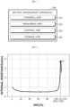
- FIG. 2 is a diagram schematically showing a resistance profile according to an embodiment of the present disclosure.
- the resistance profile may be a profile representing a corresponding relationship between the SOC and the internal resistance. Specifically, the resistance profile may be expressed as an X-Y graph when SOC is set to X and internal resistance is set to Y.
- the battery cell may be charged from SOC 0% to 113% by the charging unit 110.
- the control unit 130 may generate a resistance profile representing a corresponding relationship between the calculated internal resistance and the SOC of the battery cell.
- the control unit 130 may be configured to determine a change pattern of the internal resistance based on the generated resistance profile.
- control unit 130 may be configured to determine the change pattern of the internal resistance with respect to the reference SOC region in the generated resistance profile.
- the reference SOC region may be an SOC region exceeding a reference SOC (RSOC). That is, the control unit 130 may determine a change pattern of internal resistance for the reference SOC (RSOC) excess region in the generated resistance profile.
- RSOC reference SOC
- the reference SOC may be preset to 100%, and the reference SOC region may be preset to the SOC 100% excess region.
- the control unit 130 may determine a change pattern of the internal resistance for the SOC 100% excess region.
- the internal resistance may be increased as the SOC increases after the reference SOC (RSOC).
- the control unit 130 may determine the change pattern of internal resistance for the battery cell as an "increase and decrease pattern".
- the control unit 130 may be configured to judge whether the determined change pattern matches the criterion pattern.
- the criterion pattern may be preset as a pattern in which the internal resistance increases and then decreases in the reference SOC region. That is, the control unit 130 may judge whether the determined change pattern is a pattern in which the internal resistance increases and then decreases.
- control unit 130 may determine the change pattern of the internal resistance for the battery cell as an "increase and decrease pattern". In this case, the control unit 130 may judge that the change pattern of the internal resistance and the criterion pattern match each other.
- the control unit 130 may be configured to set a negative electrode capacity for the battery cell based on the comparison result.
- control unit 130 may calculate a N/P ratio for the battery cell based on the SOC corresponding to a point at which the internal resistance is reduced in the resistance profile.
- control unit 130 may set the negative electrode capacity for the battery cell based on the calculated N/P ratio.
- the N/P ratio may be a value obtained by dividing the negative electrode capacity calculated in consideration of the area of the negative electrode and the capacity per g (gram) by the positive electrode capacity obtained in consideration of the area of the positive electrode and the capacity per gram. That is, the N/P ratio is a negative electrode capacity ratio of the battery cell, and may be a ratio of the negative electrode capacity to the positive electrode capacity of the battery cell. For example, the N/P ratio may be calculated according to the formula "negative electrode capacity ⁇ positive electrode capacity” or "negative electrode capacity ⁇ positive electrode capacity ⁇ 100".
- this N/P ratio has a significant effect on the safety and capacity of the battery cell, it generally has a value greater than 1 (or 100%). That is, the battery cell may be manufactured so that the capacity of the included negative electrode is greater than the capacity of the positive electrode. For reference, if the N/P ratio is 1 (or 100%) or less, lithium plating in which metallic lithium is precipitated may occur during the charging and discharging of the battery cell. When lithium plating occurs, it acts as a cause of rapidly deteriorating the safety of the battery cell during high-rate discharging.
- the SOC corresponding to the point at which the internal resistance is reduced may be 111%. Accordingly, the control unit 130 may calculate the N/P ratio for the battery cell as 1.11 or 111%. In addition, the control unit 130 may set the negative electrode capacity for the battery cell based on the set N/P ratio and the positive electrode capacity for the battery cell.
- the positive electrode capacity may be preset for a battery cell in a BOL (Beginning of Life) state. Accordingly, the control unit 130 may set the negative electrode capacity corresponding to the battery cell based on the preset positive electrode capacity and the calculated N/P ratio.
- BOL Beginning of Life
- the battery management apparatus 100 has an advantage of setting the negative electrode capacity corresponding to the battery cell based on the SOC in which the internal resistance of the battery cell is reduced. That is, according to the battery management apparatus 100, the negative electrode capacity for the battery cell is not uniformly set based on the theoretical N/P ratio, but may be set through actual verification.
- the negative electrode capacity included in a cell of the same type as the battery cell may be determined. That is, in cells manufactured to correspond to the negative electrode capacity set by the battery management apparatus 100, the possibility of occurrence of lithium plating may be reduced.
- control unit 130 provided in the battery management apparatus 100 may selectively include processors known in the art, application-specific integrated circuit (ASIC), other chipsets, logic circuits, registers, communication modems, data processing devices, and the like to execute various control logic performed in the present disclosure.
- ASIC application-specific integrated circuit
- the control unit 130 may be implemented as a set of program modules.
- the program module may be stored in a memory and executed by the control unit 130.
- the memory may be located inside or out of the control unit 130 and may be connected to the control unit 130 by various well-known means.
- the battery management apparatus 100 may further include a storage unit 140.
- the storage unit 140 may store data necessary for operation and function of each component of the battery management apparatus 100, data generated in the process of performing the operation or function, or the like.
- the storage unit 140 is not particularly limited in its kind as long as it is a known information storage means that can record, erase, update and read data.
- the information storage means may include RAM, flash memory, ROM, EEPROM, registers, and the like.
- the storage unit 140 may store program codes in which processes executable by the control unit 130 are defined.
- the storage unit 140 may store information on the positive electrode capacity of the battery cell in advance.
- the control unit 130 may access the storage unit 140 to obtain the information on the positive electrode capacity of the battery cell.
- control unit 130 sets the negative electrode capacity in more detail with reference to FIG. 2 .
- the control unit 130 may be configured to determine a target peak TP in the resistance profile.
- the control unit 130 may determine the target peak TP in the reference SOC region.
- the target peak TP may be a point having an upwardly convex form in the resistance profile.
- the target peak TP may be a point at which the instantaneous change rate of the internal resistance to SOC is 0. That is, the instantaneous change rate may change from positive to negative based on the target peak TP.
- control unit 130 may determine the target peak TP in the reference SOC (RSOC) excess region.
- RSOC reference SOC
- control unit 130 may be configured to select a target SOC (TSOC) corresponding to the determined target peak TP.
- TSOC target SOC
- control unit 130 may select the target SOC (TSOC) corresponding to the target peak TP as 111%.
- TSOC target SOC
- control unit 130 may be configured to set the negative electrode capacity based on the selected target SOC (TSOC).
- control unit 130 may be configured to determine a negative electrode capacity ratio corresponding to the target SOC (TSOC).
- TSOC target SOC
- control unit 130 may determine the negative electrode capacity ratio as 1.11 or 111% based on the target SOC (TSOC).
- TSOC target SOC
- control unit 130 may be configured to set the negative electrode capacity for the battery cell based on the determined negative electrode capacity ratio.
- control unit 130 may be configured to set the negative electrode capacity for the battery cell based on the criterion ratio.
- the charging current may promote an electrochemical reaction at the interface of the negative electrode of the battery cell, thereby allowing lithium ions to be intercalated into the negative electrode.
- the internal resistance of the battery cell calculated by the oxidation-reduction reaction according to the lithium concentration of the positive electrode and the negative electrode of the battery cell may be gradually increased.
- metallic lithium is deposited on the negative electrode, a part of the charging current flows through the deposited metallic lithium, so the calculated internal resistance of the battery cell may be gradually reduced. This is because only a part of the charging current promotes the oxidation-reduction reaction.
- control unit 130 may set the negative electrode capacity of the battery cell as a sufficiently large capacity to reduce the possibility of occurrence of lithium plating, based on a larger value between the determined negative electrode capacity ratio and the criterion ratio.
- the control unit 130 may set the negative electrode capacity of the battery cell based on the determined negative electrode capacity ratio and the preset positive electrode capacity. Specifically, the control unit 130 may calculate the negative electrode capacity according to the formula "N/P ratio ⁇ positive electrode capacity" or "N/P ratio ⁇ positive electrode capacity ⁇ 100".
- the preset criterion ratio and the calculated N/P ratio are different because a SEI (Solid Electrolyte Interphase) layer is formed on the negative electrode by the reaction at the interface of the negative electrode and the electrolyte while the battery cell is being activated and the negative electrode irreversible capacity increases due to the formed SEI layer.
- SEI Solid Electrolyte Interphase
- the battery management apparatus 100 has an advantage of setting the negative electrode capacity as a larger capacity by comparing the actually measured N/P ratio of the battery cell and the preset (pre-designed) criterion ratio. Accordingly, cells manufactured based on the set negative electrode capacity may be more robust to lithium plating.
- control unit 130 may be configured to stop charging of the battery cell by controlling the charging unit 110 for a predetermined time whenever the SOC of the battery cell increases by a criterion amount.
- control unit 130 may be configured to calculate the internal resistance of the battery cell based on the battery information for the predetermined time.
- control unit 130 may stop charging for 3 seconds whenever the SOC of the battery cell increases by 1%.
- control unit 130 may calculate the internal resistance of the battery based on the voltage change rate of the battery cell for 3 seconds during which charging is stopped.
- control unit 130 may generate a resistance profile by mapping the SOC increased by 1% and the internal resistance calculated based on the voltage change rate for 3 seconds.
- an instantaneous voltage drop may occur due to electrical and electrolytic ionic resistance (Ro, ohmic resistance).
- Ro electrolytic ionic resistance
- the voltage drop according to the ohmic resistance (Ro) may be generated within about 0.1 second after the current is applied.
- a voltage drop may be generated by a resistance (R CT ) according to a charge transfer reaction between the electrode and the electrolyte surface.
- a voltage drop may be generated by a resistance (R CT ) according to the charge transfer reaction for about 3 seconds.
- a voltage drop may be generated due to a polarization resistance (R P ) according to ionic diffusion to the solid surface.
- R P polarization resistance
- the voltage drop according to the polarization resistance (R P ) may be generated linearly while the current is applied.
- the resistance (R CT ) according to the charge transfer reaction may be reduced. This is because de-intercalation and intercalation of lithium ions according to oxidation-reduction reactions at the positive electrode and the negative electrode occurs only by a part of the charging current, and the rest of the charging current flows through the metallic lithium. That is, when lithium plating occurs on the negative electrode, the resistance (R CT ) according to charge transfer reaction may be affected, among the Ohmic resistance (Ro), the resistance (R CT ) according to charge transfer reaction and the polarization resistance (R P ).
- the control unit 130 may stop charging whenever the SOC of the battery cell increases by the criterion amount, and calculate the internal resistance of the battery cell (in particular, the resistance (R CT ) according to the charge transfer reaction) based on the voltage change rate of the battery cell for a predetermined time.
- control unit 130 may stop charging whenever the SOC of the battery cell increases by 1%, and calculate the internal resistance of the battery cell based on the voltage change rate of the battery cell for 3 seconds. Thereafter, the control unit 130 may control the charging unit 110 to resume charging of the battery cell.
- the battery management apparatus 100 may be provided in a battery pack 1. That is, the battery pack 1 according to the present disclosure may include the above-described battery management apparatus 100 and one or more battery cells B. In addition, the battery pack 1 may further include electrical equipment (relays, fuses, etc.) and a case.
- FIG. 3 is a diagram schematically showing an exemplary configuration of a battery pack 1 according to another embodiment of the present disclosure.
- the measuring unit 120 may be connected to a first sensing line SL1, a second sensing line SL2, and a third sensing line SL3.
- the measuring unit 120 may measure the positive electrode voltage of the battery cell B through the first sensing line SL1, and measure the negative electrode voltage of the battery cell B through the second sensing line SL2.
- the measuring unit 120 may measure the voltage of the battery cell B by calculating a difference between the measured positive electrode voltage and the measured negative electrode voltage.
- the measuring unit 120 may be connected to a current measuring unit A through the third sensing line SL3.
- the current measuring unit A may be provided on the charging and discharging path of the battery cell B.
- the current measuring unit A may be a current meter or a shunt resistor.
- the charging and discharging path may be a high current path through which the charging current and the discharging current of the battery cell B flow.
- the measuring unit 120 may measure the current of the battery cell B through the third sensing line SL3 connected to the current measuring unit A, and measure the capacity of the battery cell B based on the measured current.
- both ends of the charging unit 110 may be connected to a charging and discharging path of the battery cell B.
- one end of the charging unit 110 may be connected to the positive electrode of the battery cell B in the charging and discharging path.
- the other end of the charging unit 110 may be connected to the negative electrode of the battery cell B in the charging and discharging path.
- the charging unit 110 may charge the battery cell B under the control of the control unit 130.
- the charging unit 110 may stop charging for a predetermined time whenever the SOC of the battery cell B increases by a criterion amount. Thereafter, after a predetermined time elapses, the charging unit 110 may charge the battery cell B again with a constant current.
- the battery management apparatus 100 may be provided in a battery manufacturing device.
- the battery manufacturing device may set a negative electrode capacity for a criterion cell and mass-produce cells of the same type based on the set negative electrode capacity. That is, the negative electrode capacity for the criterion cell may be set by the battery management apparatus 100, and cells may be manufactured according to the set negative electrode capacity.
- the cell manufactured by the battery manufacturing device since the cell manufactured by the battery manufacturing device includes a sufficiently large negative electrode capacity compared to the positive electrode capacity, the possibility of occurrence of lithium plating may be significantly reduced.
- the negative electrode capacity of the cell manufactured by the battery manufacturing device is set to correspond to the N/P ratio at which lithium plating starts to occur in an overcharged criterion cell, an optimal capacity that is not excessive may be set.
- the cell manufactured by the battery manufacturing device since the cell manufactured by the battery manufacturing device has an optimal negative electrode capacity, it may be manufactured with an optimal volume in which the possibility of occurrence of lithium plating is significantly lowered. Accordingly, the volume of a battery module, a battery pack 1, and/or a battery rack including the cells manufactured by the battery manufacturing device may also be reasonably reduced.
- FIG. 4 is a diagram schematically showing a battery management method according to still another embodiment of the present disclosure.
- each step of the battery management method may be performed by the battery management apparatus 100.
- the battery management apparatus 100 For convenience of description, contents overlapping with the previously described contents will be omitted or briefly described.
- the battery management method may include a charging step (S100), a measuring step (S200), an SOC estimating step (S300), an internal resistance calculating step (S400) and a negative electrode capacity setting step (S500).
- the charging step (S100) is a step of charging the battery cell B, and may be performed by the charging unit 110.
- the charging unit 110 may charge the battery cell B with a constant current.
- the measuring step (S200) is a step of measuring battery information including voltage and current of the battery cell B while the battery cell B is being charged, and may be performed by the measuring unit 120.
- the measuring unit 120 may measure the voltage of the battery cell B through the first sensing line SL1 and the second sensing line SL2, and measure the current of the battery cell B through the third sensing line SL3.
- the SOC estimating step (S300) is a step of estimating a SOC of the battery cell B based on the battery information measured in the measuring step (S200), and may be performed by the control unit 130.
- control unit 130 may estimate the SOC of battery cell B by using an extended Kalman filter or an ampere counting method based on the battery information.
- the internal resistance calculating step (S400) is a step of calculating an internal resistance of the battery cell B based on the battery information whenever the SOC of the battery cell B increases by a criterion amount, and may be performed by the control unit 130.
- the control unit 130 may calculate the internal resistance of the battery cell B based on the voltage change amount and the current of the battery cell B for a predetermined time. Specifically, the control unit 130 may calculate the internal resistance of the battery cell B by calculating the formula "voltage change amount ⁇ current".
- the negative electrode capacity setting step (S500) is a step of comparing the calculated internal resistance change pattern with a preset criterion pattern and setting a negative electrode capacity corresponding to the battery cell B based on the comparison result, and may be performed by the control unit 130.
- the control unit 130 may generate a resistance profile representing a corresponding relationship between the SOC and the internal resistance of the battery cell B.
- the control unit 130 may determine a target peak TP in the resistance profile and determine a negative electrode capacity ratio (e.g., N/P ratio) for the battery cell B based on a target SOC (TSOC) corresponding to the determined target peak TP.
- the control unit 130 may set an optimal negative electrode capacity for the battery cell B according to a result of comparing the determined negative electrode capacity ratio and the criterion ratio.
- the embodiments of the present disclosure described above may not be implemented only through an apparatus and a method, but may be implemented through a program that realizes a function corresponding to the configuration of the embodiments of the present disclosure or a recording medium on which the program is recorded.
- the program or recording medium may be easily implemented by those skilled in the art from the above description of the embodiments.
Landscapes
- Engineering & Computer Science (AREA)
- Power Engineering (AREA)
- Manufacturing & Machinery (AREA)
- Chemical & Material Sciences (AREA)
- Chemical Kinetics & Catalysis (AREA)
- Electrochemistry (AREA)
- General Chemical & Material Sciences (AREA)
- General Physics & Mathematics (AREA)
- Physics & Mathematics (AREA)
- Transportation (AREA)
- Mechanical Engineering (AREA)
- Microelectronics & Electronic Packaging (AREA)
- Life Sciences & Earth Sciences (AREA)
- Sustainable Development (AREA)
- Sustainable Energy (AREA)
- Secondary Cells (AREA)
- Tests Of Electric Status Of Batteries (AREA)
- Charge And Discharge Circuits For Batteries Or The Like (AREA)
Applications Claiming Priority (2)
| Application Number | Priority Date | Filing Date | Title |
|---|---|---|---|
| KR1020200160345A KR102887324B1 (ko) | 2020-11-25 | 2020-11-25 | 배터리 관리 장치 및 방법 |
| PCT/KR2021/017567 WO2022114826A1 (fr) | 2020-11-25 | 2021-11-25 | Dispositif et procédé de gestion de batterie |
Publications (2)
| Publication Number | Publication Date |
|---|---|
| EP4199176A1 true EP4199176A1 (fr) | 2023-06-21 |
| EP4199176A4 EP4199176A4 (fr) | 2024-10-23 |
Family
ID=81754809
Family Applications (1)
| Application Number | Title | Priority Date | Filing Date |
|---|---|---|---|
| EP21898652.9A Pending EP4199176A4 (fr) | 2020-11-25 | 2021-11-25 | Dispositif et procédé de gestion de batterie |
Country Status (6)
| Country | Link |
|---|---|
| US (1) | US12500433B2 (fr) |
| EP (1) | EP4199176A4 (fr) |
| JP (1) | JP7517661B2 (fr) |
| KR (1) | KR102887324B1 (fr) |
| CN (1) | CN115803935A (fr) |
| WO (1) | WO2022114826A1 (fr) |
Families Citing this family (8)
| Publication number | Priority date | Publication date | Assignee | Title |
|---|---|---|---|---|
| KR102600139B1 (ko) | 2022-07-11 | 2023-11-08 | 주식회사 엘지에너지솔루션 | 배터리 관리 장치 및 방법 |
| KR102767066B1 (ko) * | 2022-11-08 | 2025-02-11 | 주식회사 엘지에너지솔루션 | 급속 충전 제어 장치 및 방법 |
| JP7744091B2 (ja) * | 2022-11-08 | 2025-09-25 | エルジー エナジー ソリューション リミテッド | バッテリー管理システム、それを含むバッテリーパックおよびリチウム二次電池の充電プロトコルの確立方法 |
| KR20250045561A (ko) * | 2023-09-25 | 2025-04-02 | 주식회사 엘지에너지솔루션 | 충전 관리 장치 및 그것의 동작 방법 |
| KR102873125B1 (ko) * | 2023-11-20 | 2025-10-17 | 주식회사 엘지에너지솔루션 | 배터리 관리 장치, 배터리 관리 방법 및 배터리 관리 시스템 |
| KR20250098687A (ko) * | 2023-12-22 | 2025-07-01 | 주식회사 엘지에너지솔루션 | 충전 프로토콜 설정 장치 및 방법 |
| KR102915324B1 (ko) | 2024-01-23 | 2026-01-19 | 주식회사 엘지에너지솔루션 | 배터리 관리 장치 및 방법 |
| CN119749243B (zh) * | 2024-04-25 | 2025-12-16 | 比亚迪股份有限公司 | 电池保护方法及相关装置 |
Family Cites Families (34)
| Publication number | Priority date | Publication date | Assignee | Title |
|---|---|---|---|---|
| JP4144116B2 (ja) * | 1998-11-25 | 2008-09-03 | トヨタ自動車株式会社 | バッテリ充電状態検出装置 |
| JP4172222B2 (ja) | 2002-08-08 | 2008-10-29 | 日産自動車株式会社 | 電動車両の制御装置 |
| JP4095878B2 (ja) * | 2002-10-28 | 2008-06-04 | 松下電器産業株式会社 | 電池管理システム、電池パック、及びその充電状態計測方法 |
| JP5094230B2 (ja) * | 2006-08-29 | 2012-12-12 | 三洋電機株式会社 | 非水電解質二次電池 |
| JP2008253129A (ja) * | 2007-03-07 | 2008-10-16 | Matsushita Electric Ind Co Ltd | リチウム系二次電池の急速充電方法およびそれを用いる電子機器 |
| JP2010223768A (ja) | 2009-03-24 | 2010-10-07 | Panasonic Corp | 電池異常検出回路、及び電源装置 |
| JP5537236B2 (ja) | 2010-04-13 | 2014-07-02 | トヨタ自動車株式会社 | リチウムイオン二次電池の劣化判定装置および劣化判定方法 |
| JP5307113B2 (ja) * | 2010-12-20 | 2013-10-02 | 古河電気工業株式会社 | 満充電検知装置および満充電検知方法 |
| JP2014211307A (ja) | 2011-08-30 | 2014-11-13 | 三洋電機株式会社 | バッテリシステム、充電状態推定装置、電動車両、移動体、電力貯蔵装置および電源装置 |
| JP6119402B2 (ja) | 2012-05-29 | 2017-04-26 | 株式会社Gsユアサ | 内部抵抗推定装置及び内部抵抗推定方法 |
| PL3901642T3 (pl) | 2012-06-13 | 2022-11-21 | Lg Energy Solution, Ltd. | Urządzenie i sposób szacowania soc baterii akumulatorowej zawierającej mieszany materiał katodowy |
| KR101454833B1 (ko) * | 2012-12-03 | 2014-10-28 | 주식회사 엘지화학 | 이차 전지의 파라미터 추정 장치 및 방법 |
| JP6180249B2 (ja) | 2013-09-18 | 2017-08-16 | Kyb株式会社 | 電池容量推定装置及び電池容量推定方法 |
| KR101708885B1 (ko) | 2013-10-14 | 2017-02-21 | 주식회사 엘지화학 | 혼합 양극재를 포함하는 이차 전지의 상태 추정 장치 및 그 방법 |
| JP6294786B2 (ja) * | 2014-08-07 | 2018-03-14 | 矢崎総業株式会社 | 劣化要因推定方法及び余寿命推定方法 |
| KR101985812B1 (ko) * | 2015-08-18 | 2019-06-04 | 주식회사 엘지화학 | 전지 충전 한계 예측 방법과 이를 이용한 전지 급속 충전 방법 및 장치 |
| KR101897859B1 (ko) | 2015-08-24 | 2018-09-12 | 주식회사 엘지화학 | 리튬 석출 탐지 방법, 이를 이용한 이차전지 충전 방법과 장치 및 이차전지 시스템 |
| JP6265198B2 (ja) * | 2015-11-30 | 2018-01-24 | トヨタ自動車株式会社 | 全固体電池システム |
| JP2017111058A (ja) * | 2015-12-17 | 2017-06-22 | トヨタ自動車株式会社 | 電池抵抗推定装置 |
| US9840161B2 (en) * | 2016-03-10 | 2017-12-12 | Ford Global Technologies, Llc | Circuit and method for detection of battery cell degradation events |
| JP6690414B2 (ja) * | 2016-06-06 | 2020-04-28 | 日立化成株式会社 | トリクル充電電源システム |
| CN105870525B (zh) | 2016-06-20 | 2018-08-24 | 宁德新能源科技有限公司 | 电池充电的方法及装置 |
| KR102190113B1 (ko) | 2016-07-05 | 2020-12-11 | 주식회사 엘지화학 | 배터리 충전 장치 및 방법 |
| CN109463022B (zh) * | 2016-07-13 | 2022-05-06 | 株式会社村田制作所 | 电池组电路、容量系数检测方法以及存储介质 |
| CN109874354B (zh) * | 2016-09-23 | 2023-01-13 | 古河电气工业株式会社 | 二次电池状态检测装置和二次电池状态检测方法 |
| WO2018062394A1 (fr) * | 2016-09-29 | 2018-04-05 | 株式会社Gsユアサ | Dispositif d'estimation d'état de charge (soc) d'élément de stockage d'énergie, dispositif de stockage d'énergie et procédé d'estimation de soc d'élément de stockage d'énergie |
| JP6624012B2 (ja) | 2016-11-04 | 2019-12-25 | トヨタ自動車株式会社 | リチウムイオン二次電池の制御システム |
| JP6688207B2 (ja) * | 2016-11-25 | 2020-04-28 | 本田技研工業株式会社 | 二次電池の状態推定装置及び二次電池の状態推定方法 |
| JP6947014B2 (ja) | 2017-12-25 | 2021-10-13 | トヨタ自動車株式会社 | 二次電池システムおよび二次電池の制御方法 |
| JP7159590B2 (ja) * | 2018-03-28 | 2022-10-25 | 株式会社Gsユアサ | 充電制御装置、蓄電装置、蓄電素子の充電制御方法、及びコンピュータプログラム |
| WO2019199064A1 (fr) * | 2018-04-10 | 2019-10-17 | 주식회사 엘지화학 | Dispositif et procédé de diagnostic de batterie |
| JP7254482B2 (ja) * | 2018-11-07 | 2023-04-10 | 古河電気工業株式会社 | 充電可能電池状態検出装置および充電可能電池状態検出方法 |
| KR102405514B1 (ko) * | 2018-12-06 | 2022-06-03 | 주식회사 엘지에너지솔루션 | 이차 전지의 충전 장치 및 방법 |
| JP7039499B2 (ja) | 2019-01-04 | 2022-03-22 | 株式会社東芝 | 内部状態推定装置および方法、ならびに電池制御装置 |
-
2020
- 2020-11-25 KR KR1020200160345A patent/KR102887324B1/ko active Active
-
2021
- 2021-11-25 WO PCT/KR2021/017567 patent/WO2022114826A1/fr not_active Ceased
- 2021-11-25 EP EP21898652.9A patent/EP4199176A4/fr active Pending
- 2021-11-25 US US18/007,582 patent/US12500433B2/en active Active
- 2021-11-25 CN CN202180049579.9A patent/CN115803935A/zh active Pending
- 2021-11-25 JP JP2022576888A patent/JP7517661B2/ja active Active
Also Published As
| Publication number | Publication date |
|---|---|
| US12500433B2 (en) | 2025-12-16 |
| KR20220072578A (ko) | 2022-06-02 |
| EP4199176A4 (fr) | 2024-10-23 |
| US20230238815A1 (en) | 2023-07-27 |
| JP7517661B2 (ja) | 2024-07-17 |
| CN115803935A (zh) | 2023-03-14 |
| KR102887324B1 (ko) | 2025-11-14 |
| WO2022114826A1 (fr) | 2022-06-02 |
| JP2023530297A (ja) | 2023-07-14 |
Similar Documents
| Publication | Publication Date | Title |
|---|---|---|
| US12500433B2 (en) | Battery management apparatus and method | |
| US20230179007A1 (en) | Battery Management Apparatus and Method | |
| US20240044995A1 (en) | Battery Management Apparatus and Method | |
| EP4163655B1 (fr) | Appareil et procédé de gestion de batterie | |
| EP4199182A1 (fr) | Dispositif et procédé de diagnostic de batterie | |
| EP4145158B1 (fr) | Dispositif et procédé de diagnostic de batterie | |
| CN112601969A (zh) | 使用非破坏性电阻分析的电池管理装置和方法 | |
| EP4376161A1 (fr) | Appareil et procédé de gestion de batterie | |
| US12352818B2 (en) | Battery management apparatus and method | |
| EP3839532B1 (fr) | Dispositif et procédé d'estimation d'état de charge | |
| US11835586B2 (en) | Battery management apparatus and method | |
| CN115667957B (zh) | 电池管理设备、电池检测装置及电池管理方法 | |
| US20250316780A1 (en) | Battery Management Apparatus and Method | |
| US20250052821A1 (en) | Battery state estimating apparatus and method | |
| US12282068B2 (en) | Lithium precipitation detecting apparatus and method | |
| CN114175449A (zh) | 用于供应应急电源的设备 | |
| EP4556924A1 (fr) | Appareil et procédé de gestion de batterie | |
| EP4733786A1 (fr) | Appareil et procédé de diagnostic de batterie | |
| EP4733788A1 (fr) | Appareil et procédé de gestion de batterie | |
| US20250264539A1 (en) | Apparatus and method for estimating capacity of battery | |
| EP4650804A1 (fr) | Appareil et procédé de diagnostic de batterie | |
| CN121986271A (en) | Apparatus and method for diagnosing battery | |
| AU2025231196A1 (en) | Apparatus and method for managing battery | |
| CN120883419A (zh) | 电池管理装置和方法 |
Legal Events
| Date | Code | Title | Description |
|---|---|---|---|
| STAA | Information on the status of an ep patent application or granted ep patent |
Free format text: STATUS: THE INTERNATIONAL PUBLICATION HAS BEEN MADE |
|
| PUAI | Public reference made under article 153(3) epc to a published international application that has entered the european phase |
Free format text: ORIGINAL CODE: 0009012 |
|
| STAA | Information on the status of an ep patent application or granted ep patent |
Free format text: STATUS: REQUEST FOR EXAMINATION WAS MADE |
|
| 17P | Request for examination filed |
Effective date: 20230317 |
|
| AK | Designated contracting states |
Kind code of ref document: A1 Designated state(s): AL AT BE BG CH CY CZ DE DK EE ES FI FR GB GR HR HU IE IS IT LI LT LU LV MC MK MT NL NO PL PT RO RS SE SI SK SM TR |
|
| DAV | Request for validation of the european patent (deleted) | ||
| DAX | Request for extension of the european patent (deleted) | ||
| A4 | Supplementary search report drawn up and despatched |
Effective date: 20240925 |
|
| RIC1 | Information provided on ipc code assigned before grant |
Ipc: H01M 10/00 20060101ALI20240919BHEP Ipc: B60L 58/12 20190101ALI20240919BHEP Ipc: B60L 53/62 20190101ALI20240919BHEP Ipc: G01R 31/389 20190101ALI20240919BHEP Ipc: G01R 31/387 20190101ALI20240919BHEP Ipc: H01M 10/48 20060101ALI20240919BHEP Ipc: H01M 10/42 20060101AFI20240919BHEP |
|
| STAA | Information on the status of an ep patent application or granted ep patent |
Free format text: STATUS: EXAMINATION IS IN PROGRESS |
|
| 17Q | First examination report despatched |
Effective date: 20250612 |
|
| GRAP | Despatch of communication of intention to grant a patent |
Free format text: ORIGINAL CODE: EPIDOSNIGR1 |
|
| STAA | Information on the status of an ep patent application or granted ep patent |
Free format text: STATUS: GRANT OF PATENT IS INTENDED |
|
| INTG | Intention to grant announced |
Effective date: 20260317 |