EP4199225A1 - Module de batterie, et bloc-batterie et véhicule le comprenant - Google Patents
Module de batterie, et bloc-batterie et véhicule le comprenant Download PDFInfo
- Publication number
- EP4199225A1 EP4199225A1 EP22825224.3A EP22825224A EP4199225A1 EP 4199225 A1 EP4199225 A1 EP 4199225A1 EP 22825224 A EP22825224 A EP 22825224A EP 4199225 A1 EP4199225 A1 EP 4199225A1
- Authority
- EP
- European Patent Office
- Prior art keywords
- case
- battery
- battery module
- bolt
- fastening member
- Prior art date
- Legal status (The legal status is an assumption and is not a legal conclusion. Google has not performed a legal analysis and makes no representation as to the accuracy of the status listed.)
- Pending
Links
Images


Classifications
-
- H—ELECTRICITY
- H01—ELECTRIC ELEMENTS
- H01M—PROCESSES OR MEANS, e.g. BATTERIES, FOR THE DIRECT CONVERSION OF CHEMICAL ENERGY INTO ELECTRICAL ENERGY
- H01M50/00—Constructional details or processes of manufacture of the non-active parts of electrochemical cells other than fuel cells, e.g. hybrid cells
- H01M50/30—Arrangements for facilitating escape of gases
- H01M50/342—Non-re-sealable arrangements
- H01M50/3425—Non-re-sealable arrangements in the form of rupturable membranes or weakened parts, e.g. pierced with the aid of a sharp member
-
- H—ELECTRICITY
- H01—ELECTRIC ELEMENTS
- H01M—PROCESSES OR MEANS, e.g. BATTERIES, FOR THE DIRECT CONVERSION OF CHEMICAL ENERGY INTO ELECTRICAL ENERGY
- H01M50/00—Constructional details or processes of manufacture of the non-active parts of electrochemical cells other than fuel cells, e.g. hybrid cells
- H01M50/20—Mountings; Secondary casings or frames; Racks, modules or packs; Suspension devices; Shock absorbers; Transport or carrying devices; Holders
- H01M50/204—Racks, modules or packs for multiple batteries or multiple cells
-
- H—ELECTRICITY
- H01—ELECTRIC ELEMENTS
- H01M—PROCESSES OR MEANS, e.g. BATTERIES, FOR THE DIRECT CONVERSION OF CHEMICAL ENERGY INTO ELECTRICAL ENERGY
- H01M50/00—Constructional details or processes of manufacture of the non-active parts of electrochemical cells other than fuel cells, e.g. hybrid cells
- H01M50/20—Mountings; Secondary casings or frames; Racks, modules or packs; Suspension devices; Shock absorbers; Transport or carrying devices; Holders
- H01M50/204—Racks, modules or packs for multiple batteries or multiple cells
- H01M50/207—Racks, modules or packs for multiple batteries or multiple cells characterised by their shape
- H01M50/209—Racks, modules or packs for multiple batteries or multiple cells characterised by their shape adapted for prismatic or rectangular cells
-
- H—ELECTRICITY
- H01—ELECTRIC ELEMENTS
- H01M—PROCESSES OR MEANS, e.g. BATTERIES, FOR THE DIRECT CONVERSION OF CHEMICAL ENERGY INTO ELECTRICAL ENERGY
- H01M50/00—Constructional details or processes of manufacture of the non-active parts of electrochemical cells other than fuel cells, e.g. hybrid cells
- H01M50/20—Mountings; Secondary casings or frames; Racks, modules or packs; Suspension devices; Shock absorbers; Transport or carrying devices; Holders
- H01M50/218—Mountings; Secondary casings or frames; Racks, modules or packs; Suspension devices; Shock absorbers; Transport or carrying devices; Holders characterised by the material
- H01M50/22—Mountings; Secondary casings or frames; Racks, modules or packs; Suspension devices; Shock absorbers; Transport or carrying devices; Holders characterised by the material of the casings or racks
- H01M50/222—Inorganic material
- H01M50/224—Metals
-
- H—ELECTRICITY
- H01—ELECTRIC ELEMENTS
- H01M—PROCESSES OR MEANS, e.g. BATTERIES, FOR THE DIRECT CONVERSION OF CHEMICAL ENERGY INTO ELECTRICAL ENERGY
- H01M50/00—Constructional details or processes of manufacture of the non-active parts of electrochemical cells other than fuel cells, e.g. hybrid cells
- H01M50/20—Mountings; Secondary casings or frames; Racks, modules or packs; Suspension devices; Shock absorbers; Transport or carrying devices; Holders
- H01M50/233—Mountings; Secondary casings or frames; Racks, modules or packs; Suspension devices; Shock absorbers; Transport or carrying devices; Holders characterised by physical properties of casings or racks, e.g. dimensions
- H01M50/24—Mountings; Secondary casings or frames; Racks, modules or packs; Suspension devices; Shock absorbers; Transport or carrying devices; Holders characterised by physical properties of casings or racks, e.g. dimensions adapted for protecting batteries from their environment, e.g. from corrosion
-
- H—ELECTRICITY
- H01—ELECTRIC ELEMENTS
- H01M—PROCESSES OR MEANS, e.g. BATTERIES, FOR THE DIRECT CONVERSION OF CHEMICAL ENERGY INTO ELECTRICAL ENERGY
- H01M50/00—Constructional details or processes of manufacture of the non-active parts of electrochemical cells other than fuel cells, e.g. hybrid cells
- H01M50/20—Mountings; Secondary casings or frames; Racks, modules or packs; Suspension devices; Shock absorbers; Transport or carrying devices; Holders
- H01M50/249—Mountings; Secondary casings or frames; Racks, modules or packs; Suspension devices; Shock absorbers; Transport or carrying devices; Holders specially adapted for aircraft or vehicles, e.g. cars or trains
-
- H—ELECTRICITY
- H01—ELECTRIC ELEMENTS
- H01M—PROCESSES OR MEANS, e.g. BATTERIES, FOR THE DIRECT CONVERSION OF CHEMICAL ENERGY INTO ELECTRICAL ENERGY
- H01M50/00—Constructional details or processes of manufacture of the non-active parts of electrochemical cells other than fuel cells, e.g. hybrid cells
- H01M50/20—Mountings; Secondary casings or frames; Racks, modules or packs; Suspension devices; Shock absorbers; Transport or carrying devices; Holders
- H01M50/262—Mountings; Secondary casings or frames; Racks, modules or packs; Suspension devices; Shock absorbers; Transport or carrying devices; Holders with fastening means, e.g. locks
-
- H—ELECTRICITY
- H01—ELECTRIC ELEMENTS
- H01M—PROCESSES OR MEANS, e.g. BATTERIES, FOR THE DIRECT CONVERSION OF CHEMICAL ENERGY INTO ELECTRICAL ENERGY
- H01M50/00—Constructional details or processes of manufacture of the non-active parts of electrochemical cells other than fuel cells, e.g. hybrid cells
- H01M50/30—Arrangements for facilitating escape of gases
-
- H—ELECTRICITY
- H01—ELECTRIC ELEMENTS
- H01M—PROCESSES OR MEANS, e.g. BATTERIES, FOR THE DIRECT CONVERSION OF CHEMICAL ENERGY INTO ELECTRICAL ENERGY
- H01M50/00—Constructional details or processes of manufacture of the non-active parts of electrochemical cells other than fuel cells, e.g. hybrid cells
- H01M50/30—Arrangements for facilitating escape of gases
- H01M50/308—Detachable arrangements, e.g. detachable vent plugs or plug systems
-
- H—ELECTRICITY
- H01—ELECTRIC ELEMENTS
- H01M—PROCESSES OR MEANS, e.g. BATTERIES, FOR THE DIRECT CONVERSION OF CHEMICAL ENERGY INTO ELECTRICAL ENERGY
- H01M50/00—Constructional details or processes of manufacture of the non-active parts of electrochemical cells other than fuel cells, e.g. hybrid cells
- H01M50/30—Arrangements for facilitating escape of gases
- H01M50/317—Re-sealable arrangements
- H01M50/325—Re-sealable arrangements comprising deformable valve members, e.g. elastic or flexible valve members
-
- H—ELECTRICITY
- H01—ELECTRIC ELEMENTS
- H01M—PROCESSES OR MEANS, e.g. BATTERIES, FOR THE DIRECT CONVERSION OF CHEMICAL ENERGY INTO ELECTRICAL ENERGY
- H01M50/00—Constructional details or processes of manufacture of the non-active parts of electrochemical cells other than fuel cells, e.g. hybrid cells
- H01M50/30—Arrangements for facilitating escape of gases
- H01M50/342—Non-re-sealable arrangements
-
- B—PERFORMING OPERATIONS; TRANSPORTING
- B60—VEHICLES IN GENERAL
- B60L—PROPULSION OF ELECTRICALLY-PROPELLED VEHICLES; SUPPLYING ELECTRIC POWER FOR AUXILIARY EQUIPMENT OF ELECTRICALLY-PROPELLED VEHICLES; ELECTRODYNAMIC BRAKE SYSTEMS FOR VEHICLES IN GENERAL; MAGNETIC SUSPENSION OR LEVITATION FOR VEHICLES; MONITORING OPERATING VARIABLES OF ELECTRICALLY-PROPELLED VEHICLES; ELECTRIC SAFETY DEVICES FOR ELECTRICALLY-PROPELLED VEHICLES
- B60L50/00—Electric propulsion with power supplied within the vehicle
- B60L50/50—Electric propulsion with power supplied within the vehicle using propulsion power supplied by batteries or fuel cells
- B60L50/60—Electric propulsion with power supplied within the vehicle using propulsion power supplied by batteries or fuel cells using power supplied by batteries
- B60L50/64—Constructional details of batteries specially adapted for electric vehicles
-
- H—ELECTRICITY
- H01—ELECTRIC ELEMENTS
- H01M—PROCESSES OR MEANS, e.g. BATTERIES, FOR THE DIRECT CONVERSION OF CHEMICAL ENERGY INTO ELECTRICAL ENERGY
- H01M2220/00—Batteries for particular applications
- H01M2220/20—Batteries in motive systems, e.g. vehicle, ship, plane
-
- H—ELECTRICITY
- H01—ELECTRIC ELEMENTS
- H01M—PROCESSES OR MEANS, e.g. BATTERIES, FOR THE DIRECT CONVERSION OF CHEMICAL ENERGY INTO ELECTRICAL ENERGY
- H01M50/00—Constructional details or processes of manufacture of the non-active parts of electrochemical cells other than fuel cells, e.g. hybrid cells
- H01M50/20—Mountings; Secondary casings or frames; Racks, modules or packs; Suspension devices; Shock absorbers; Transport or carrying devices; Holders
- H01M50/204—Racks, modules or packs for multiple batteries or multiple cells
- H01M50/207—Racks, modules or packs for multiple batteries or multiple cells characterised by their shape
- H01M50/211—Racks, modules or packs for multiple batteries or multiple cells characterised by their shape adapted for pouch cells
-
- H—ELECTRICITY
- H01—ELECTRIC ELEMENTS
- H01M—PROCESSES OR MEANS, e.g. BATTERIES, FOR THE DIRECT CONVERSION OF CHEMICAL ENERGY INTO ELECTRICAL ENERGY
- H01M50/00—Constructional details or processes of manufacture of the non-active parts of electrochemical cells other than fuel cells, e.g. hybrid cells
- H01M50/20—Mountings; Secondary casings or frames; Racks, modules or packs; Suspension devices; Shock absorbers; Transport or carrying devices; Holders
- H01M50/204—Racks, modules or packs for multiple batteries or multiple cells
- H01M50/207—Racks, modules or packs for multiple batteries or multiple cells characterised by their shape
- H01M50/213—Racks, modules or packs for multiple batteries or multiple cells characterised by their shape adapted for cells having curved cross-section, e.g. round or elliptic
-
- Y—GENERAL TAGGING OF NEW TECHNOLOGICAL DEVELOPMENTS; GENERAL TAGGING OF CROSS-SECTIONAL TECHNOLOGIES SPANNING OVER SEVERAL SECTIONS OF THE IPC; TECHNICAL SUBJECTS COVERED BY FORMER USPC CROSS-REFERENCE ART COLLECTIONS [XRACs] AND DIGESTS
- Y02—TECHNOLOGIES OR APPLICATIONS FOR MITIGATION OR ADAPTATION AGAINST CLIMATE CHANGE
- Y02E—REDUCTION OF GREENHOUSE GAS [GHG] EMISSIONS, RELATED TO ENERGY GENERATION, TRANSMISSION OR DISTRIBUTION
- Y02E60/00—Enabling technologies; Technologies with a potential or indirect contribution to GHG emissions mitigation
- Y02E60/10—Energy storage using batteries
Definitions
- the present disclosure relates to a battery module, and a battery pack and a vehicle including the battery module, and more particular, to a battery module, which may smoothly discharge gas generated in a case, and a battery pack and a vehicle including the battery module.
- a nickel-cadmium battery or a hydrogen ion battery has been used as the secondary battery.
- a lithium secondary battery is recently widely used because charging and discharging is free due to rare memory effect in comparison with a nickel-based secondary battery, a self-discharge rate is very low, and an energy density is high.
- the lithium secondary battery mainly uses a lithium oxide and a carbonaceous material as a positive electrode active material and a negative electrode active material, respectively.
- the lithium secondary battery includes an electrode assembly in which a positive electrode plate and a negative electrode plate, respectively coated with the positive electrode active material and the negative electrode active material, are arranged with a separator therebetween, and an exterior, that is a battery case, which seals and receives the electrode assembly together with an electrolyte solution.
- the lithium secondary battery includes a positive electrode, a negative electrode, and a separator interposed therebetween and an electrolyte.
- the lithium secondary battery is classified into a lithium ion battery (LIB) and a polymer lithium ion battery (PLIB).
- LIB lithium ion battery
- PKIB polymer lithium ion battery
- an electrode of the lithium secondary battery is prepared by applying the positive or negative electrode active material to a current collector made of aluminum or copper sheet, mesh, film, foil, or the like and then drying the same.
- various types of secondary batteries include a case capable of protecting the battery cells, a battery module in which a plurality of battery cells are stacked and inserted into the case, and a battery pack including a plurality of battery modules.
- a lithium secondary battery may generate gas inside the secondary battery during charging and discharging of the secondary battery, and this gas may cause damage to the secondary battery as well as an explosion or ignition, which is more problematic.
- the secondary battery explodes or catches fire, this may not only damage a device to which the secondary battery is applied, but also cause injuries to a user who uses the secondary battery. Also, due to the damage to the exterior of the secondary battery, an electrolyte inside the secondary battery may leak and cause damage such as short circuit or electric shock.
- a structure for discharging gas when the gas is generated inside the secondary battery may be provided.
- the present disclosure is directed to providing a battery module, which may smoothly discharge gas when the gas is generated in a case, and a battery pack and a vehicle including the battery module.
- a battery module comprising: a plurality of battery cells; a case in which the plurality of battery cells are accommodated; and a fastening member fastened to the case, wherein gas generated inside the case is discharged through the fastening member.
- a venting hole through which the gas is discharged may be formed in the fastening member.
- the fastening member may include a bolt disposed from a lower side of the inside of the case toward an upper side thereof to protrude to the outside of the case and having a male thread portion, the venting hole being formed in the bolt; and a nut having a female thread portion to be coupled to the bolt at an outer side of the case.
- the fastening member may include a bolt disposed from an inner side of the case toward a side surface thereof to protrude to the outside of the case and having a male thread portion, the venting hole being formed in the bolt; and a nut having a female thread portion to be coupled to the bolt at an outer side of the case.
- a female thread portion may be formed on the case, and the fastening member may be provided as a screw disposed from a lower side of the inside of the case toward an upper side thereof to protrude to the outside of the case and having a male thread portion formed to be fastened with the female thread portion of the case, the venting hole being formed in the screw.
- the fastening member may include a body portion in which the venting hole is formed; and a rupturing portion coupled to an end of the body portion and ruptured by the gas generated inside the case.
- the rupturing portion may be formed thinner than the body portion.
- a rupturing groove may be formed on the rupturing portion so that the rupturing portion is ruptured by a pressure of the gas.
- the body portion and the rupturing portion may be made of different materials.
- the body portion may be made of a metal material
- the rupturing portion may be made of a composite resin material.
- a battery pack comprising the battery module or a vehicle comprising the battery module.
- the gas since the gas may be discharged through the fastening member, the gas generated inside the case may be smoothly discharged.
- 'coupling' or 'connecting' may refer not only to a case where one member and another member are directly combined or directly connected but also a case where one member is indirectly combined with another member via a connecting member or is indirectly connected.
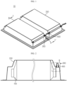
- FIG. 1 is a perspective view showing a battery module according to an embodiment of the present disclosure as a whole
- FIG. 2 is a cross-sectional view taken along line A-A' of FIG. 1
- FIG. 3 is an enlarged view showing a portion B of FIG. 2
- FIG. 4 is a perspective view showing a bolt in a fastening members of the battery module according to an embodiment of the present disclosure
- FIG. 5 is a diagram showing another embodiment of FIG. 3
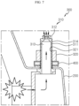
- FIGS. 6 and 7 are diagrams for illustrating a process in which gas inside a case is discharged through the fastening member in the battery module according to an embodiment of the present disclosure.
- a battery module 10 includes a plurality of battery cells 100, a case 200, and a fastening member 300.
- the battery cell 100 may be diverse.
- the battery cell 100 may be provided as a pouch-type battery cell or as a cylindrical battery cell.
- the battery cell 100 includes an electrode lead, and the electrode lead provided in the battery cell 100 is a type of terminal connected to an external device, and a conductive material may be used.
- the electrode leads may include a positive electrode lead and a negative electrode lead.
- the positive electrode lead and the negative electrode lead may be disposed in opposite directions with respect to the longitudinal direction of the battery cell 100, or the positive electrode lead and the negative electrode lead may be located in the same direction with respect to the longitudinal direction of the battery cell 100.
- the positive electrode lead and the negative electrode lead may be made of various materials.
- the positive electrode lead may be made of an aluminum material
- the negative electrode lead may be made of a copper material.
- the electrode leads may be electrically coupled to a bus bar 400.
- the battery cell 100 may have a structure in which a plurality of unit cells, in each of which a positive electrode plate, a separator and a negative electrode plate are arranged in order, or a plurality of bi-cells, in each of which a positive electrode plate, a separator, a negative electrode plate, a separator, a positive electrode plate, a separator and a negative electrode plate are arranged in order, are stacked suitable for a battery capacity.
- the plurality of battery cells 100 may be accommodated in the case 200 in various ways, and, for example, the plurality of battery cells 100 may be stacked on each other and accommodated in the form of a battery cell stack.
- the battery cell 100 may have various structures, and the plurality of battery cells 100 may be stacked in various ways.
- the battery cell stack may include a plurality of cartridges (not shown) for respectively accommodating the battery cells 100.
- Each cartridge (not shown) may be manufactured by injection-molding plastic, and a plurality of cartridges (not shown), each having an accommodation portion capable of accommodating the battery cell 100, may be stacked.
- a cartridge assembly in which the plurality of cartridges (not shown) are stacked may have a connector element or a terminal element.
- the connector element may include, for example, various types of electrical connection parts or members for connection to a battery management system (BMS) that may provide data on voltage or temperature of the battery cell 100.
- BMS battery management system
- the terminal element includes a positive terminal and a negative terminal as main terminals connected to the battery cell 100.
- a plurality of battery cells 100 for example, a battery cell stack or a cartridge assembly in which the battery cell stack is accommodated, is accommodated in the case 200.
- the case 200 may be provided to surround the battery cell stack formed by the battery cells 100 or the cartridge assembly in which the battery cell stack is accommodated. That is, the case 200 surrounds the entire battery cells 100 and thereby protects the battery cells 100 from external vibration or impact.
- the case 200 may be formed in a shape corresponding to the shape of the battery cells 100, for example, the battery cell stack or the cartridge assembly.
- the case 200 may also be provided in a hexahedral shape to correspond thereto.
- the battery cells 100 accommodated in the case 200 generate gas therein during the charging and discharging process, and the gas generated inside the case 200 in this way is discharged through the fastening member 300.
- the fastening member 300 may have a venting hole 313 through which the gas may be discharged. This will be described later in detail.
- the fastening member 300 is fastened to the case 200.
- the fastening member 300 may fasten the case 200 itself, or may be coupled to the case 200 to fix the bus bar 400.
- the fastening member 300 may be configured to include a bolt 310 and a nut 320 as an embodiment, and may also be configured to include a screw 330 coupled directly to the case 200 as another embodiment.
- the fastening member 300 includes a bolt 310 and a nut 320.
- the bolt 310 is disposed from a lower side of the inside of the case 200 toward an upper side to protrude to the outside of the case 200.
- the venting hole 313 is formed in the bolt 310.
- the bolt 310 may be disposed from an inner side of the case 200 toward a side surface to protrude to the outside of the case 200.
- the venting hole 313 is formed in the bolt 310.
- the bolt 310 may be disposed from the inner side of the case 200 toward a bottom to protrude to the outside of the case 200.
- the bolt 310 may include a body portion 311 and a rupturing portion 312.
- the venting hole 313 is formed in the body portion 311. That is, the hollow venting hole 313 through which gas can move is formed inside the body portion 311.
- a male thread portion 314 is formed around the outer circumference of the body portion 311.
- the rupturing portion 312 is coupled to an end of the body portion 311 and is provided to be ruptured by the gas generated inside the case 200. That is, when the gas pressure inside the case 200 exceeds a preset value, the rupturing portion 312 may be ruptured.
- the rupturing portion 312 may be formed thinner than the body portion 311 so as to be ruptured by gas pressure.
- a rupturing groove 315 may be formed on the rupturing portion 312 so that the rupturing portion 312 may be easily ruptured by gas pressure.
- the rupturing groove 315 is formed in a cross shape in FIG. 4 , the shape of the rupturing groove 315 may be diverse.
- the body portion 311 and the rupturing portion 312 may be made of different materials.
- the body portion 311 may be made of a metal material in consideration of rigidity
- the rupturing portion 312 may be made of various composite resin materials to facilitate rupture.
- the rupturing portion 312 may be made of, for example, a thin plastic material to be easily ruptured.
- the rupturing portion 312 may be made of a polyethylene film, but the material of the rupturing portion 312 is not limited thereto.
- the body portion 311 and the rupturing portion 312 made of different materials may be prepared by an insert injection method.
- the manufacturing method is not limited to insert injection.
- the nut 320 is coupled to the bolt 310 at an outer side of the case 200.
- a female thread portion 321 that may correspond to the male thread portion 314 of the bolt 310 is formed on the nut 320.
- the bolt 310 is disposed from the lower side of the inside of the case 200 toward the upper side, and the nut 320 is provided to be coupled to the bolt 310 at the outer side of the case 200. That is, the bolt 310 is located at the inner side of the case 200, and the nut 320 is located at the outer side of the case 200.
- the bolt 310 may be disposed to face the side surface from the inner side of the case 200, and the nut 320 may be provided to be coupled to the bolt 310 at the outer side of the case 200. Also in this case, the bolt 310 is located at the inner side of the case 200, and the nut 320 is located at the outer side of the case 200.
- the bus bar 400 may be interposed and fixed between the bolt 310 and the nut 320.
- the bolt 310 and the nut 320 which serve as the fastening member 300, are shown to fix the bus bar 400, but the bolt 310 and the nut 320 may be provided to fix only the case 200 or may be provided to fix both the case 200 and the bus bar 400.
- the movement direction of gas may be guided according to the arrangement direction of the bolt 310. That is, since the gas generated inside the case 200 moves along the venting hole 313 formed in the bolt 310, if the bolt 310 is disposed from the lower side to the upper side of the case 200 as shown in FIG. 2 , the gas may be discharged to the outside of the case 200 while moving along the venting hole 313 from the lower side toward the upper side of the case 200.
- the gas may be discharged to the outside of the case 200 while moving along the venting hole 313 toward the side surface of the case 200.
- the body portion 311 may guide the movement direction of gas, thereby discharging the gas in the direction desired by a user.
- the fastening member 300 has both the function of fastening the case 200 or the function of fastening the bus bar 400 as well as the gas discharge function as described above, both functions are possible with only the fastening member 300, and a separate component is not necessary to discharge the gas, thereby giving an effect of facilitating the production and reducing the cost.
- the fastening member 300 includes a screw 330 having a male thread portion 331 formed on a periphery thereof to be directly coupled to the case 200
- the bolt 310 is coupled to the nut 320
- the screw 330 is directly coupled to the case 200, different from the former embodiment.
- Other basic configuration of the screw 330 for example the body portion and the rupturing portion, is common with the bolt 310, so the common portion of the screw 330 and the bolt 310 is replaced with the above description of the bolt 310.
- the case 200 has a female thread portion 210.
- the fastening member 300 includes only the screw 330, the nut 320 is unnecessary, and the male thread portion 331 formed on the screw 330 is coupled to the female thread portion 210 formed on the case 200.
- the fastening member 300 is disposed from the lower side of the inside of the case 200 toward the upper side, similar to the bolt 310 and is fastened to the female thread portion 210 of the case 200 to protrude to the outside of the case 200.
- a venting hole 332 is formed in the screw 330.
- the screw 330 may be used for fastening and fixing the case 200 rather than the bus bar 400.
- the present disclosure is not limited thereto, and the screw 330 may be provided to fix the bus bar 400 together with other members, for example, a washer, if necessary.
- a plurality of battery cells 100 are accommodated in the case 200, and a fastening member 300 for fixing the case 200 or fixing the bus bar 400 or the like is fastened to the case 200.
- venting holes 313, 332 having a hollow shape through which gas may move may be formed inside the fastening member 300.
- gas is generated inside the case 200 so that the gas pressure presses the rupturing portion 312 of the bolt 310, and referring to FIG. 7 , the rupturing portion 312 is ruptured by the gas pressure so that the gas inside the case 200 is discharged to the outside of the case 200.
- a battery pack (not shown) may include at least one battery module 10 according to an embodiment of the present disclosure as described above. Also, in addition to the battery modules 10, the battery pack (not shown) may further include a housing for accommodating the battery modules 10, and various devices for controlling charge and discharge of the battery modules 10, such as a BMS, a current sensor, a fuse, and the like.
- a vehicle (not shown) may include the battery module 10 or the battery pack (not shown) described above, and the battery pack (not shown) may include the battery module 10.
- the battery module 10 according to an embodiment of the present disclosure may be applied to the vehicle (not shown), for example a predetermined vehicle (not shown) provided to use electricity such as an electric vehicle or a hybrid electric vehicle.
- the present disclosure relates to a battery module, a battery pack and a vehicle including the same, and in particular, it may be used in industries related to secondary batteries.
Landscapes
- Chemical & Material Sciences (AREA)
- Chemical Kinetics & Catalysis (AREA)
- Electrochemistry (AREA)
- General Chemical & Material Sciences (AREA)
- Engineering & Computer Science (AREA)
- Aviation & Aerospace Engineering (AREA)
- Inorganic Chemistry (AREA)
- Battery Mounting, Suspending (AREA)
- Gas Exhaust Devices For Batteries (AREA)
Applications Claiming Priority (2)
| Application Number | Priority Date | Filing Date | Title |
|---|---|---|---|
| KR1020210078975A KR102929568B1 (ko) | 2021-06-17 | 2021-06-17 | 배터리 모듈, 이를 포함하는 배터리 팩 및 자동차 |
| PCT/KR2022/008168 WO2022265299A1 (fr) | 2021-06-17 | 2022-06-09 | Module de batterie, et bloc-batterie et véhicule le comprenant |
Publications (2)
| Publication Number | Publication Date |
|---|---|
| EP4199225A1 true EP4199225A1 (fr) | 2023-06-21 |
| EP4199225A4 EP4199225A4 (fr) | 2024-07-31 |
Family
ID=84527212
Family Applications (1)
| Application Number | Title | Priority Date | Filing Date |
|---|---|---|---|
| EP22825224.3A Pending EP4199225A4 (fr) | 2021-06-17 | 2022-06-09 | Module de batterie, et bloc-batterie et véhicule le comprenant |
Country Status (6)
| Country | Link |
|---|---|
| US (1) | US20230299412A1 (fr) |
| EP (1) | EP4199225A4 (fr) |
| JP (1) | JP7592156B2 (fr) |
| KR (1) | KR102929568B1 (fr) |
| CN (1) | CN116250142A (fr) |
| WO (1) | WO2022265299A1 (fr) |
Families Citing this family (1)
| Publication number | Priority date | Publication date | Assignee | Title |
|---|---|---|---|---|
| KR20250152346A (ko) * | 2024-04-16 | 2025-10-23 | 주식회사 엘지에너지솔루션 | 배터리 팩 및 이를 포함하는 자동차 |
Family Cites Families (24)
| Publication number | Priority date | Publication date | Assignee | Title |
|---|---|---|---|---|
| EP0739047A3 (fr) * | 1995-04-21 | 1999-04-07 | Wako Electronics Co., Ltd. | Dispositif de sécurité pour une batterie secondaire |
| GB0012031D0 (en) * | 2000-05-19 | 2000-07-05 | Yuasa Automotive Batteries Eur | Battery vent plug |
| KR100549814B1 (ko) * | 2003-07-12 | 2006-02-08 | 주식회사 네스캡 | 안전변 장착 구조물 및 이를 포함하는 전기에너지 저장장치 |
| JP4635483B2 (ja) * | 2003-09-29 | 2011-02-23 | 日産自動車株式会社 | 電池収納ケース、電池モジュール、および、組電池 |
| JP2006210257A (ja) * | 2005-01-31 | 2006-08-10 | Gs Yuasa Corporation:Kk | 蓄電池 |
| JP2009231180A (ja) * | 2008-03-25 | 2009-10-08 | Panasonic Corp | 鉛蓄電池 |
| JP5350959B2 (ja) * | 2009-09-29 | 2013-11-27 | 日本特殊陶業株式会社 | 燃料電池スタック及び燃料電池 |
| JP3162199U (ja) * | 2010-04-19 | 2010-08-26 | 千如電機工業股▲ふん▼有限公司 | 二次電池の蓋密閉体 |
| KR101316319B1 (ko) * | 2011-10-10 | 2013-10-08 | 기아자동차주식회사 | 차량의 고전압배터리 에어브리더 |
| CN102969469B (zh) * | 2012-11-19 | 2015-11-04 | 广东志成冠军集团有限公司 | 一种大容量动力锂电池安全阀 |
| CN204230326U (zh) * | 2014-11-27 | 2015-03-25 | 惠州比亚迪实业有限公司 | 一种动力电池包 |
| JP2016139483A (ja) * | 2015-01-26 | 2016-08-04 | 日立化成株式会社 | 蓄電モジュール |
| KR101831817B1 (ko) * | 2015-03-20 | 2018-02-23 | 주식회사 엘지화학 | 가스 배출 수단 및 내,외부의 압력 보상 수단을 갖는 차량용 배터리 팩 |
| KR20170000070A (ko) * | 2015-06-23 | 2017-01-02 | 김한섭 | Vrla 배터리용 마개 |
| KR102518866B1 (ko) | 2016-03-03 | 2023-04-06 | 에스케이온 주식회사 | 벤팅부를 포함하는 이차전지 |
| CN110190212B (zh) * | 2018-12-29 | 2020-02-04 | 比亚迪股份有限公司 | 动力电池包及车辆 |
| JP2020113488A (ja) * | 2019-01-15 | 2020-07-27 | 三菱自動車工業株式会社 | 電池パックの排水構造 |
| KR102415558B1 (ko) * | 2019-02-11 | 2022-07-01 | 주식회사 엘지에너지솔루션 | 냉각제가 배터리 모듈 내로 투입될 수 있는 구조를 갖는 에너지 저장 시스템 |
| KR102168725B1 (ko) * | 2019-04-30 | 2020-10-22 | 한국전력공사 | 슈퍼 커패시터용 단자 연결 구조 |
| CN112331992B (zh) * | 2019-11-08 | 2021-12-03 | 宁德时代新能源科技股份有限公司 | 电池包及装置 |
| WO2021097644A1 (fr) * | 2019-11-19 | 2021-05-27 | 宁德时代新能源科技股份有限公司 | Bloc-batterie et équipement de transport |
| KR102779617B1 (ko) * | 2019-12-02 | 2025-03-10 | 주식회사 엘지에너지솔루션 | 전지팩 및 이를 포함하는 디바이스 |
| KR102322713B1 (ko) | 2019-12-19 | 2021-11-04 | 주식회사 포스코 | 내열성과 성형성이 우수한 냉연강판 및 그 제조방법 |
| CN114156589B (zh) * | 2020-09-05 | 2024-09-13 | Tvs电机股份有限公司 | 能量储存单元模块 |
-
2021
- 2021-06-17 KR KR1020210078975A patent/KR102929568B1/ko active Active
-
2022
- 2022-06-09 CN CN202280005827.4A patent/CN116250142A/zh active Pending
- 2022-06-09 US US18/021,346 patent/US20230299412A1/en active Pending
- 2022-06-09 JP JP2023518028A patent/JP7592156B2/ja active Active
- 2022-06-09 WO PCT/KR2022/008168 patent/WO2022265299A1/fr not_active Ceased
- 2022-06-09 EP EP22825224.3A patent/EP4199225A4/fr active Pending
Also Published As
| Publication number | Publication date |
|---|---|
| WO2022265299A1 (fr) | 2022-12-22 |
| US20230299412A1 (en) | 2023-09-21 |
| JP7592156B2 (ja) | 2024-11-29 |
| KR20220168906A (ko) | 2022-12-26 |
| KR102929568B1 (ko) | 2026-02-20 |
| JP2023542176A (ja) | 2023-10-05 |
| CN116250142A (zh) | 2023-06-09 |
| EP4199225A4 (fr) | 2024-07-31 |
Similar Documents
| Publication | Publication Date | Title |
|---|---|---|
| US11121395B2 (en) | Battery module with movable end plate responsive to cell swelling and battery pack including same | |
| EP3540817B1 (fr) | Bloc-batterie | |
| EP3573131B1 (fr) | Module de batterie et procédé de fabrication de module de batterie | |
| US20250079548A1 (en) | Battery Module, and Battery Pack and Vehicle Comprising Same | |
| US20260074338A1 (en) | Secondary battery module, and secondary battery pack and vehicle comprising same | |
| US11289765B2 (en) | Battery housing and battery module comprising same | |
| US20230261303A1 (en) | Battery module, and battery pack and automobile including same | |
| EP4199225A1 (fr) | Module de batterie, et bloc-batterie et véhicule le comprenant | |
| US12592448B2 (en) | Battery module, and battery pack and vehicle comprising same | |
| CN222168649U (zh) | 电池装置及用电装置 | |
| EP3514004B1 (fr) | Module de batterie et batterie comprenant celui-ci | |
| EP4087012B1 (fr) | Module de batterie et bloc-batterie, et véhicule comprenant ceux-ci | |
| EP4322300B1 (fr) | Boîtier de batterie, module de batterie, bloc-batterie, et véhicule avec le boîtier de batterie, et procédé de fabrication de boîtier de batterie | |
| EP4336639B1 (fr) | Module de batterie, bloc-batterie et véhicule le comprenant |
Legal Events
| Date | Code | Title | Description |
|---|---|---|---|
| STAA | Information on the status of an ep patent application or granted ep patent |
Free format text: STATUS: THE INTERNATIONAL PUBLICATION HAS BEEN MADE |
|
| PUAI | Public reference made under article 153(3) epc to a published international application that has entered the european phase |
Free format text: ORIGINAL CODE: 0009012 |
|
| STAA | Information on the status of an ep patent application or granted ep patent |
Free format text: STATUS: REQUEST FOR EXAMINATION WAS MADE |
|
| 17P | Request for examination filed |
Effective date: 20230317 |
|
| AK | Designated contracting states |
Kind code of ref document: A1 Designated state(s): AL AT BE BG CH CY CZ DE DK EE ES FI FR GB GR HR HU IE IS IT LI LT LU LV MC MK MT NL NO PL PT RO RS SE SI SK SM TR |
|
| A4 | Supplementary search report drawn up and despatched |
Effective date: 20240627 |
|
| RIC1 | Information provided on ipc code assigned before grant |
Ipc: H01M 50/213 20210101ALI20240621BHEP Ipc: H01M 50/211 20210101ALI20240621BHEP Ipc: H01M 50/249 20210101ALI20240621BHEP Ipc: H01M 50/262 20210101ALI20240621BHEP Ipc: H01M 50/342 20210101AFI20240621BHEP |
|
| DAV | Request for validation of the european patent (deleted) | ||
| DAX | Request for extension of the european patent (deleted) |