EP4199242A1 - Appareil et système de communication - Google Patents
Appareil et système de communication Download PDFInfo
- Publication number
- EP4199242A1 EP4199242A1 EP21865839.1A EP21865839A EP4199242A1 EP 4199242 A1 EP4199242 A1 EP 4199242A1 EP 21865839 A EP21865839 A EP 21865839A EP 4199242 A1 EP4199242 A1 EP 4199242A1
- Authority
- EP
- European Patent Office
- Prior art keywords
- phase shifter
- phase
- combiner
- coupled
- phase difference
- Prior art date
- Legal status (The legal status is an assumption and is not a legal conclusion. Google has not performed a legal analysis and makes no representation as to the accuracy of the status listed.)
- Pending
Links
- 238000004891 communication Methods 0.000 title claims abstract description 93
- 230000010363 phase shift Effects 0.000 claims description 70
- 238000003491 array Methods 0.000 claims description 6
- 238000010586 diagram Methods 0.000 description 33
- 230000005855 radiation Effects 0.000 description 12
- 238000000034 method Methods 0.000 description 10
- 238000004088 simulation Methods 0.000 description 10
- 238000004590 computer program Methods 0.000 description 7
- 230000008569 process Effects 0.000 description 5
- 230000008859 change Effects 0.000 description 4
- 230000006870 function Effects 0.000 description 3
- 230000008878 coupling Effects 0.000 description 2
- 238000010168 coupling process Methods 0.000 description 2
- 238000005859 coupling reaction Methods 0.000 description 2
- 230000000694 effects Effects 0.000 description 2
- 238000005516 engineering process Methods 0.000 description 2
- 238000012986 modification Methods 0.000 description 2
- 230000004048 modification Effects 0.000 description 2
- 230000005540 biological transmission Effects 0.000 description 1
- 238000004364 calculation method Methods 0.000 description 1
- 230000003287 optical effect Effects 0.000 description 1
Images


Classifications
-
- H—ELECTRICITY
- H01—ELECTRIC ELEMENTS
- H01Q—ANTENNAS, i.e. RADIO AERIALS
- H01Q3/00—Arrangements for changing or varying the orientation or the shape of the directional pattern of the waves radiated from an antenna or antenna system
- H01Q3/26—Arrangements for changing or varying the orientation or the shape of the directional pattern of the waves radiated from an antenna or antenna system varying the relative phase or relative amplitude of energisation between two or more active radiating elements; varying the distribution of energy across a radiating aperture
- H01Q3/30—Arrangements for changing or varying the orientation or the shape of the directional pattern of the waves radiated from an antenna or antenna system varying the relative phase or relative amplitude of energisation between two or more active radiating elements; varying the distribution of energy across a radiating aperture varying the relative phase between the radiating elements of an array
- H01Q3/34—Arrangements for changing or varying the orientation or the shape of the directional pattern of the waves radiated from an antenna or antenna system varying the relative phase or relative amplitude of energisation between two or more active radiating elements; varying the distribution of energy across a radiating aperture varying the relative phase between the radiating elements of an array by electrical means
- H01Q3/40—Arrangements for changing or varying the orientation or the shape of the directional pattern of the waves radiated from an antenna or antenna system varying the relative phase or relative amplitude of energisation between two or more active radiating elements; varying the distribution of energy across a radiating aperture varying the relative phase between the radiating elements of an array by electrical means with phasing matrix
-
- H—ELECTRICITY
- H01—ELECTRIC ELEMENTS
- H01P—WAVEGUIDES; RESONATORS, LINES, OR OTHER DEVICES OF THE WAVEGUIDE TYPE
- H01P1/00—Auxiliary devices
- H01P1/18—Phase-shifters
-
- H—ELECTRICITY
- H01—ELECTRIC ELEMENTS
- H01P—WAVEGUIDES; RESONATORS, LINES, OR OTHER DEVICES OF THE WAVEGUIDE TYPE
- H01P1/00—Auxiliary devices
- H01P1/20—Frequency-selective devices, e.g. filters
- H01P1/213—Frequency-selective devices, e.g. filters combining or separating two or more different frequencies
-
- H—ELECTRICITY
- H01—ELECTRIC ELEMENTS
- H01P—WAVEGUIDES; RESONATORS, LINES, OR OTHER DEVICES OF THE WAVEGUIDE TYPE
- H01P5/00—Coupling devices of the waveguide type
- H01P5/12—Coupling devices having more than two ports
-
- H—ELECTRICITY
- H01—ELECTRIC ELEMENTS
- H01Q—ANTENNAS, i.e. RADIO AERIALS
- H01Q21/00—Antenna arrays or systems
-
- H—ELECTRICITY
- H01—ELECTRIC ELEMENTS
- H01Q—ANTENNAS, i.e. RADIO AERIALS
- H01Q3/00—Arrangements for changing or varying the orientation or the shape of the directional pattern of the waves radiated from an antenna or antenna system
- H01Q3/26—Arrangements for changing or varying the orientation or the shape of the directional pattern of the waves radiated from an antenna or antenna system varying the relative phase or relative amplitude of energisation between two or more active radiating elements; varying the distribution of energy across a radiating aperture
- H01Q3/30—Arrangements for changing or varying the orientation or the shape of the directional pattern of the waves radiated from an antenna or antenna system varying the relative phase or relative amplitude of energisation between two or more active radiating elements; varying the distribution of energy across a radiating aperture varying the relative phase between the radiating elements of an array
- H01Q3/34—Arrangements for changing or varying the orientation or the shape of the directional pattern of the waves radiated from an antenna or antenna system varying the relative phase or relative amplitude of energisation between two or more active radiating elements; varying the distribution of energy across a radiating aperture varying the relative phase between the radiating elements of an array by electrical means
-
- H—ELECTRICITY
- H04—ELECTRIC COMMUNICATION TECHNIQUE
- H04B—TRANSMISSION
- H04B7/00—Radio transmission systems, i.e. using radiation field
- H04B7/02—Diversity systems; Multi-antenna system, i.e. transmission or reception using multiple antennas
- H04B7/04—Diversity systems; Multi-antenna system, i.e. transmission or reception using multiple antennas using two or more spaced independent antennas
- H04B7/0408—Diversity systems; Multi-antenna system, i.e. transmission or reception using multiple antennas using two or more spaced independent antennas using two or more beams, i.e. beam diversity
-
- H—ELECTRICITY
- H04—ELECTRIC COMMUNICATION TECHNIQUE
- H04B—TRANSMISSION
- H04B7/00—Radio transmission systems, i.e. using radiation field
- H04B7/02—Diversity systems; Multi-antenna system, i.e. transmission or reception using multiple antennas
- H04B7/04—Diversity systems; Multi-antenna system, i.e. transmission or reception using multiple antennas using two or more spaced independent antennas
- H04B7/06—Diversity systems; Multi-antenna system, i.e. transmission or reception using multiple antennas using two or more spaced independent antennas at the transmitting station
- H04B7/0613—Diversity systems; Multi-antenna system, i.e. transmission or reception using multiple antennas using two or more spaced independent antennas at the transmitting station using simultaneous transmission
- H04B7/0615—Diversity systems; Multi-antenna system, i.e. transmission or reception using multiple antennas using two or more spaced independent antennas at the transmitting station using simultaneous transmission of weighted versions of same signal
- H04B7/0617—Diversity systems; Multi-antenna system, i.e. transmission or reception using multiple antennas using two or more spaced independent antennas at the transmitting station using simultaneous transmission of weighted versions of same signal for beam forming
-
- H—ELECTRICITY
- H04—ELECTRIC COMMUNICATION TECHNIQUE
- H04B—TRANSMISSION
- H04B7/00—Radio transmission systems, i.e. using radiation field
- H04B7/02—Diversity systems; Multi-antenna system, i.e. transmission or reception using multiple antennas
- H04B7/04—Diversity systems; Multi-antenna system, i.e. transmission or reception using multiple antennas using two or more spaced independent antennas
- H04B7/08—Diversity systems; Multi-antenna system, i.e. transmission or reception using multiple antennas using two or more spaced independent antennas at the receiving station
- H04B7/0837—Diversity systems; Multi-antenna system, i.e. transmission or reception using multiple antennas using two or more spaced independent antennas at the receiving station using pre-detection combining
- H04B7/0842—Weighted combining
- H04B7/086—Weighted combining using weights depending on external parameters, e.g. direction of arrival [DOA], predetermined weights or beamforming
Definitions
- Embodiments of this application relate to the field of communication technologies, and in particular, to a communication apparatus and system.
- ground base station communication and satellite communication selective transmission and reception are performed by using a plurality of beams, to reduce interference to a neighboring cell and interference from the neighboring cell.
- the plurality of beams help implement spatial division multiplexing, and improve a capacity of a communication system.
- the plurality of beams may be implemented through digital beamforming, analog beamforming, and hybrid beamforming.
- a direction of each beam may be independently and flexibly adjusted.
- a quantity of radio frequency links required by digital beamforming is equal to a quantity of antennas in an antenna array; and when a scale of the antenna array is expanded, a quantity of required analog-to-digital converters and a quantity of required digital-to-analog converters are also large, which results in high power consumption.
- no analog-to-digital converter or digital-to-analog converter is required, and power consumption is greatly reduced.
- the beam formed through analog beamforming cannot be flexibly adjusted and controlled.
- a plurality of beams that can be flexibly adjusted and controlled are formed through hybrid beamforming by using a fully connected structure.
- a large quantity of phase shifters are required in this manner for implementation. For example, if T beams are generated simultaneously by using a two-dimensional array including N ⁇ M antenna arrays, T ⁇ N ⁇ M phase shifters are required. It can be learned that the plurality of beams formed through existing beamforming cannot meet a service requirement, and a feed network is urgently required, to form a plurality of beams that can be flexibly adjusted and controlled and reduce a quantity of phase shifters as much as possible under a condition of low power consumption.
- Embodiments of this application provide a communication apparatus and system, to reduce a quantity of phase shifters, flexibly adjust and control a plurality of beams, and implement independent scanning by each beam.
- coupling mentioned in this application may be understood as a direct connection between two components, or may be understood as an indirect connection between two components.
- a first phase shifter is coupled to a first combiner.
- the direct connection may be understood as a direct connection between the first phase shifter and the first combiner.
- the indirect connection may be understood as a connection between the first phase shifter and the first combiner after any quantity of phase shifters are connected, or may be further understood as a connection between the first phase shifter and the first combiner by using a resistor.
- an embodiment of this application provides a communication apparatus.
- the communication apparatus includes a phase shift unit, an input port, and an output port.
- the phase shift unit includes at least one first structure.
- the first structure includes a first phase difference coupler, a second phase difference coupler, a first phase shifter, a second phase shifter, a third phase shifter, a fourth phase shifter, a fifth phase shifter, a sixth phase shifter, a cross coupler, a first combiner, and a second combiner.
- the first phase difference coupler is coupled to the third phase shifter and the fourth phase shifter, and is coupled to the cross coupler and the first combiner.
- the second phase difference coupler is coupled to the fifth phase shifter and the sixth phase shifter, and is coupled to the second phase shifter and the second combiner.
- a second output port of the first phase difference coupler is coupled to a first input port of the cross coupler
- a first output port of the second phase difference coupler is coupled to an input port of the second phase shifter
- an output port of the second phase shifter is coupled to a second input port of the cross coupler.
- the input port is coupled to an input port of the third phase shifter, an input port of the fourth phase shifter, an input port of the fifth phase shifter, and an input port the sixth phase shifter.
- the output port is coupled to an output port of the first phase shifter and an output port of the second combiner.
- phase difference couplers when beamforming is performed by using the communication apparatus, because the phase difference couplers are introduced to reduce a quantity of phase shifters required during beamforming, and signals in different channels may share the first phase shifter and the second phase shifter, the quantity of the phase shifters is reduced, device overheads during beamforming are reduced, and power consumption of the device is reduced in a case of phase shifter multiplexing.
- phase difference values of the phase difference couplers and phase shift values of the phase shifters are adjusted, so that a plurality of beams can be flexibly adjusted and controlled, and independent scanning by each beam can be implemented.
- the phase shift unit further includes a second structure.
- the second structure includes a third phase difference coupler, a seventh phase shifter, an eighth phase shifter, and a ninth phase shifter.
- the third phase difference coupler is coupled to the eighth phase shifter and the ninth phase shifter, and is coupled to the seventh phase shifter.
- the input port is coupled to an input port of the eighth phase shifter and an input port of the ninth phase shifter.
- the output port is coupled to an output port of the seventh phase shifter.
- phase shift unit when the phase shift unit performs beamforming by using the second structure, a quantity of phase shifters may also be reduced, a plurality of beams can be flexibly adjusted and controlled, and independent scanning by each beam can be implemented.
- first structure and the second structure may be combined to implement beamforming, to adjust more beams flexibly by using the communication apparatus.
- the phase shift unit further includes a third structure.
- the third structure includes a power splitter, a tenth phase shifter, and an eleventh phase shifter.
- the power splitter is coupled to the tenth phase shifter and the eleventh phase shifter.
- the input port is coupled to an input port of the eleventh phase shifter.
- the output port is coupled to an output port of the tenth phase shifter.
- beamforming may be implemented by combining the first structure and the third structure, to adjust more beams flexibly by using the communication apparatus.
- the input port of the apparatus is coupled to the power splitter.
- the input port of the communication apparatus is coupled to the power splitter, to divide a signal from a radio frequency unit into multi-channel signals and input the multi-channel signals to the communication apparatus.
- the apparatus further includes a third combiner and a fourth combiner.
- the third combiner may combine signals from output ports of first phase shifters in the first structures
- the fourth combiner may combine signals from output ports of second combiners in the first structures.
- the third combiner may combine a signal from an output port of a first phase shifter in the first structure and a signal from an output port of a seventh phase shifter in the second structure
- the fourth combiner may combine a signal from an output port of a second combiner in the first structure and a signal from a second output port of a third phase difference coupler in the second structure.
- the third combiner may combine a signal from an output port of a first phase shifter in the first structure and a signal from an output port of a tenth phase shifter in the third structure
- the fourth combiner may combine a signal from an output port of a second combiner in the first structure and a signal from a second output port of a power splitter in the third structure.
- the apparatus further includes a fifth combiner, a sixth combiner, a seventh combiner, an eighth combiner, a fourth phase difference coupler, and a fifth phase difference coupler.
- the phase shift unit includes a plurality of first structures, and the first structures are arranged in sequence in the phase shift unit
- the fifth combiner may combine signals from output ports of first phase shifters in odd-numbered first structures, and an output port of the fifth combiner is coupled to a first input port of the fourth phase difference coupler
- the sixth combiner may combine signals from output ports of second combiners in odd-numbered first structures, and an output port of the sixth combiner is coupled to a first input port of the fifth phase difference coupler
- the seventh combiner may combine signals from output ports of first phase shifters in even-numbered first structures, and an output port of the seventh combiner is coupled to a second input port of the fourth phase difference coupler
- the eighth combiner may combine signals from output ports of second combiners in even-numbered first structures, and an output port of the eighth combiner is coupled to a
- the fifth combiner may combine a signal from an output port of a first phase shifter in an odd-numbered first structure and a signal from an output port of a seventh phase shifter in the second structure, and the output port of the fifth combiner is coupled to the first input port of the fourth phase difference coupler;
- the sixth combiner may combine a signal from an output port of a second combiner in an odd-numbered first structure and a signal from the second output port of a third phase difference coupler in the second structure, and the output port of the sixth combiner is coupled to the first input port of the fifth phase difference coupler;
- the seventh combiner may combine signals from output ports of first phase shifters in even-numbered first structures, and the output port of the seventh combiner is coupled to the second input port of the fourth coupler; and the eighth combiner may combine signals from output ports of second combiners in even-numbered first structures, and the output port of the eighth combiner is coupled to the second input port of the fifth phase difference coupler.
- the fifth combiner may combine a signal from an output port of a first phase shifter in an odd-numbered first structure and a signal from an output port of a tenth phase shifter in the third structure, and the output port of the fifth combiner is coupled to the first input port of the fourth phase difference coupler;
- the sixth combiner may combine a signal from an output port of a second combiner in an odd-numbered first structure and a signal from a second output port of a power splitter in the third structure, and the output port of the sixth combiner is coupled to the first input port of the fifth phase difference coupler;
- the seventh combiner may combine signals from output ports of first phase shifters in even-numbered first structures, and the output port of the seventh combiner is coupled to the second input port of the fourth coupler; and the eighth combiner may combine signals from output ports of second combiners in even-numbered first structures, and the output port of the eighth combiner is coupled to the second input port of the fifth phase difference coupler.
- the phase shift unit includes a plurality of first structures that are arranged in sequence, for example, 10 first structures
- the foregoing odd-numbered first structure may be understood as a first first structure, a third first structure, a fifth first structure, a seventh first structure, and a ninth first structure
- the foregoing even-numbered first structure may be understood as a second first structure, a fourth first structure, a sixth first structure, an eighth first structure, and a tenth first structure.
- a signal combination manner is not limited to the foregoing signal combination manners. Another signal combination manner may be further included. This is not specifically limited herein in this application.
- the fifth combiner may combine signals from output ports of first phase shifters of a first structure to an n th structure
- the sixth combiner may combine signals from output ports of second combiners of the first first structure to the n th first structure
- the seventh combiner may combine signals from output ports of first phase shifters of an n +1 th first structure to a 2 n th first structure
- the eighth combiner may combine signals from output ports of second combiners of the n +1 th first structure to the 2 n th first structure.
- n is an integer
- n is greater than or equal to 0. Any manner in which output signals of the phase shift unit are combined by using the fifth combiner, the sixth combiner, the seventh combiner, and the eighth combiner is applicable to this application.
- the communication apparatus further includes a controller.
- the controller is configured to adjust a parameter of the phase shift unit.
- the parameter includes at least one of the following: a parameter of the first phase difference coupler, a parameter of the second phase difference coupler, a parameter of the third phase difference coupler, a parameter of the first phase shifter, a parameter of the second phase shifter, a parameter of the third phase shifter, a parameter of the fourth phase shifter, a parameter of the fifth phase shifter, a parameter of the sixth phase shifter, a parameter of the seventh phase shifter, a parameter of the eighth phase shifter, a parameter of the ninth phase shifter, a parameter of the tenth phase shifter, and a parameter of the eleventh phase shifter.
- the controller may adjust the phase difference values of the phase difference couplers and the phase shift values of the phase shifters in the phase shift unit. Therefore, beams having different directions are determined by using the communication apparatus.
- an embodiment of this application further provides a communication system, including a plurality of antenna arrays and the communication apparatus according to the first aspect.
- the antenna array is connected to an output port of the communication apparatus, and the antenna array is configured to output beams having different directions.
- the communication system further includes a radio frequency unit.
- the radio frequency unit is connected to an input port of the communication apparatus, and the radio frequency unit is configured to input a signal to the communication apparatus.
- an embodiment of this application provides a control method.
- the method may be applied to the communication system according to the second aspect.
- the method includes: A radio frequency unit receives a radio frequency signal sent by the radio frequency unit; and sends the radio frequency signal to a communication apparatus, to enable an antenna array to output beams having different directions.
- phase difference values of phase difference couplers and phase shift values of phase shifters in the communication apparatus may be determined by a controller after directions of required beams are determined.
- an embodiment of this application provides a system.
- the system may be an electronic device.
- a scale of an antenna array is increasingly large. Power consumption of an ultra-large-scale antenna array cannot be ignored.
- a plurality of beams whose directions are adjustable are implemented through analog beamforming with low power consumption, and reducing a quantity of phase shifters with a fully connected architecture becomes a problem that needs to be resolved urgently at present.
- this application provides a communication apparatus to reduce a quantity of phase shifters required during beamforming, and implement a plurality of beams whose directions can be flexibly adjusted and controlled.
- connection means an electrical connection
- a connection between two electrical elements may be a direct or indirect connection between the two electrical elements.
- a connection between A and B may represent that A and B are directly connected to each other, or A and B are indirectly connected to each other by using one or more other electrical elements.
- the connection between A and B may also represent that A is directly connected to C, C is directly connected to B, and A and B are connected to each other through C.
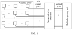
- FIG. 1 is a schematic diagram of a communication system to which an embodiment of this application is applicable.
- the communication system includes a radio frequency unit, a communication apparatus, and an antenna array.
- the antenna array is connected to output ports of the communication apparatus.
- the radio frequency unit is connected to input ports of the communication apparatus.
- the antenna array is configured to output beams having different directions.
- the radio frequency unit is configured to input a signal to the communication apparatus. If the communication apparatus includes T input ports and MN output ports, a phase shift amount of a feed signal required for beamforming may be provided for each antenna unit in the antenna array. As shown in FIG.
- T streams of radio frequency signals are input from the T input ports of the T -input- MN -output communication apparatus, and each stream of signals is output through the MN output ports of the communication apparatus.
- Phase distribution of the output signals may enable the antenna array connected to the communication apparatus to radiate a beam in a specific direction.
- a maximum quantity of beams that can be simultaneously generated is equal to a quantity of input ports of the communication apparatus.
- a direction of each beam may be changed independently and flexibly by adjusting a phase difference value of a phase difference coupler and a phase shift value of a phase shifter in the communication apparatus.
- the communication apparatus includes a phase shift unit 1, input ports 2, and output ports 3.
- the phase shift unit 1 includes at least one first structure 1-0.
- the first structure 1-0 includes a first phase difference coupler 1-0-1, a second phase difference coupler 1-0-2, a first phase shifter 1-0-3, a second phase shifter 1-0-4, a third phase shifter 1-0-5, a fourth phase shifter 1-0-6, a fifth phase shifter 1-0-7, a sixth phase shifter 1-0-8, a cross coupler 1-0-9, a first combiner 1-0-10, and a second combiner 1-0-11.
- the first phase difference coupler 1-0-1 is coupled to the third phase shifter 1-0-5 and the fourth phase shifter 1-0-6, and is coupled to the cross coupler 1-0-9 and the first combiner 1-0-10.
- the second phase difference coupler 1-0-2 is coupled to the fifth phase shifter 1-0-7 and the sixth phase shifter 1-0-8, and is coupled to the second phase shifter 1-0-4 and the second combiner 1-0-11.
- a second output port of the first phase difference coupler 1-0-1 is coupled to a first input port of the cross coupler 1-0-9.
- a first output port of the second phase difference coupler 1-0-2 is coupled to an input port of the second phase shifter 1-0-4.
- An output port of the second phase shifter 1-0-4 is coupled to a second input port of the cross coupler 1-0-9.
- the input ports 2 are coupled to an input port of the third phase shifter 1-0-5, an input port of the fourth phase shifter 1-0-6, an input port of the fifth phase shifter 1-0-7, and an input port of the sixth phase shifter 1-0-8 respectively.
- the output ports 3 are coupled to an output port of the first phase shifter 1-0-3 and an output port of the second combiner 1-0-11 respectively.
- phase difference coupler when signals are input at different input ports of the phase difference coupler, and phase differences between output signals at output ports of the phase difference coupler are different. For example, for a phase difference coupler with a phase difference of x 1 between an upper output port and a lower output port, when a signal is input from an upper input port of the phase difference coupler, the upper output port and the lower output port of the phase difference coupler output signals with an equal signal amplitude and a phase difference of x 1 . When a signal is input from a lower input port of the phase difference coupler, the upper output port and the lower output port of the phase difference coupler output signals with an equal signal amplitude and a phase difference of - x 1 .
- the third phase shifter 1-0-5, the fourth phase shifter 1-0-6, the fifth phase shifter 1-0-7, and the sixth phase shifter 1-0-8 may be coupled to the input ports of the communication apparatus.
- the first structure 1-0 may further not include the sixth phase shifter 1-0-8, and the third phase shifter 1-0-5, the fourth phase shifter 1-0-6, and the fifth phase shifter 1-0-7 in the first structure 1-0 are coupled to the input ports of the communication apparatus.
- the phase shift unit 1 may further include a second structure 1-1, as shown in FIG. 3 .
- the second structure 1-1 includes a third phase difference coupler 1-1-1, a seventh phase shifter 1-1-2, an eighth phase shifter 1-1-3, and a ninth phase shifter 1-1-4.
- the third phase difference coupler 1-1-1 is coupled to the eighth phase shifter 1-1-3 and the ninth phase shifter 1-1-4, and is coupled to the seventh phase shifter 1-1-2.
- the input ports 2 are coupled to an input port of the eighth phase shifter 1-1-3 and an input port of the ninth phase shifter 1-1-4.
- the output port 3 is coupled to an output port of the seventh phase shifter 1-1-2.
- the following uses the second structure 1-1 as an example to briefly describe how to determine a phase difference value of the third phase difference coupler 1-1-1 and a phase shift value of the seventh phase shifter 1-1-2. Because there is a one-to-one correspondence between a phase difference between input signals of adjacent units of a radiation array and a direction of an array radiation beam, the output port of the seventh phase shifter 1-1-2 and an output port of the third phase difference coupler 1-1-1 in the second structure 1-1 are coupled to the signal output ports of the communication apparatus, a target direction required for a radiation beam may be used to determine a phase difference between an output signal from the output port of the third phase difference coupler 1-1-1 and an output signal from the output port of the seventh phase shifter 1-1-2 in the second structure 1-1.
- phase differences between adjacent units of a required array, determined based on directions of corresponding radiation beams are respectively PD 4 n +1 and PD 4 n +2
- a phase shift value of the seventh phase shifter 1-1-2 is PS 7
- a phase shift value of the eighth phase shifter 1-1-3 is PS 8
- a phase shift value of the ninth phase shifter 1-1-4 is PS 9
- a phase difference value of the third phase difference coupler 1-1-1 is x 3 .
- a signal from a radio frequency unit passes through the eighth phase shifter 1-1-3 with a phase shift of -PS 8 .
- the signal is input to a first input port of the third phase difference coupler 1-1-1 and output from a first output port of the third phase difference coupler 1-1-1 without a phase change, namely, -PS 8 -0. Then, an output signal passes through the seventh phase shifter 1-1-2 with a phase shift of -PS 8 -0-PS 7 .
- the signal from the radio frequency unit passes through the eighth phase shifter 1-1-3 with a phase shift of -PS 8 .
- the signal is input to the first input port of the third phase difference coupler 1-1-1 and output from a second output port of the third phase difference coupler 1-1-1 with a phase change of - x 3 . Therefore, the signal is changed to -PS 8 - x 3 .
- the signal from the radio frequency unit passes through the ninth phase shifter 1-1-4 with a phase shift of -PS 9 . Because the signal is input to a second input port of the third phase difference coupler 1-1-1 and output from the first output port of the third phase difference coupler 1-1-1, with a phase change of - x 3 , a phase shift is -PS 9 - x 3 . Then, an output signal passes through the seventh phase shifter 1-1-2, and becomes -PS 9 - x 3 -PS 7 .
- the signal from the radio frequency unit passes through the ninth phase shifter 1-1-4 with a phase shift of -PS 9 . Because the signal is input to the second input port of the third phase difference coupler 1-1-1 and output from the second output port of the third phase difference coupler 1-1-1 without a phase change, the signal is still -PS 9 .
- a phase difference value of the first phase difference coupler 1-0-1, a phase difference value of the second phase difference coupler 1-0-2, a phase shift value of the first phase shifter 1-0-3, and a phase shift value of the second phase shifter 1-0-4 may all be determined in a manner similar to the foregoing manner.
- the phase shift unit 1 may further include a third structure 1-2, as shown in FIG. 4 .
- the third structure 1-2 includes a power splitter 1-2-1, a tenth phase shifter 1-2-2, and an eleventh phase shifter 1-2-3.
- the power splitter 1-2-1 is coupled to the tenth phase shifter 1-2-2 and the eleventh phase shifter 1-2-3.
- the input port 2 is coupled to an input port of the eleventh phase shifter 1-2-3.
- the output port 3 is coupled to an output port of the tenth phase shifter 1-2-2.
- the first structure 1-0 may be understood as a structure with four inputs and two outputs, or may be understood as a structure with three inputs and two outputs.
- the second structure 1-1 may be understood as a structure with two inputs and two outputs.
- the third structure 1-2 may be understood as a structure with one input and two outputs.
- the communication apparatus may be constructed based on the first structure 1-0, the second structure 1-1, and the third structure 1-2. Therefore, a third combiner 5 and a fourth combiner 6 are further introduced in this application. Signals output by the first structure 1-0, the second structure 1-1, and the third structure 1-2 may be combined by using the third combiner 5 and the fourth combiner 6, as shown in FIG. 5a to FIG. 5c .
- the third combiner 5 may combine signals from output ports of the first phase shifter 1-0-3 in the first structure 1-0
- the fourth combiner 6 may combine signals from output ports of the second combiner 1-0-11 in the first structure 1-0, as shown in FIG. 5a .
- the third combiner 5 may combine a signal from the output port of the first phase shifter 1-0-3 in the first structure 1-0 and a signal from an output port of the seventh phase shifter 1-1-2 in the second structure 1-1
- the fourth combiner 6 may combine a signal from the output port of the second combiner 1-0-11 in the first structure 1-0 and a signal from a second output port of the third phase difference coupler 1-1-1 in the second structure 1-1, as shown in FIG. 5b .
- the third combiner 5 may combine a signal from the output port of the first phase shifter 1-0-3 in the first structure 1-0 and a signal from an output port of the tenth phase shifter 1-2-2 in the third structure 1-2
- the fourth combiner 6 may combine a signal from the output port of the second combiner 1-0-11 in the first structure 1-0 and a signal from the power splitter 1-2-1 in the third structure 1-2, as shown in FIG. 5c .
- a quantity of first structures 1-0, a quantity of second structures 1-1, and a quantity of third structures 1-2 that are specifically selected to construct the communication apparatus may be determined by dividing a quantity of input ports by 4 (because the first structure 1-0 may be coupled to a maximum of four input ports, the quantity of the first structures 1-0, the quantity of the second structures 1-1, and the quantity of the third structures 1-2 that are required by the communication apparatus may be better determined by dividing the quantity of the input ports by 4).
- a quantity of input ports T is 17, and a quotient of dividing 17 by 4 is 4, with a remainder of 1, four first structures 1-0 (4 inputs and 2 outputs), one third structure 1-2, one third combiner 5, and one fourth combiner 6 may be selected to construct the communication apparatus.
- the quantity of the input ports T is 18, and a quotient of dividing 18 by 4 is 4, with a remainder of 2, four first structures 1-0 (4 inputs and 2 outputs), one second structure, one third combiner 5, and one fourth combiner 6 may be selected to construct the communication apparatus.
- the quantity of the input ports T is 19, and a quotient of dividing 19 by 4 is 4, with a remainder of 3, four first structures 1-0 (4 inputs and 2 outputs), one first structure 1-0 (3 inputs and 2 outputs), one third combiner 5, and one fourth combiner 6 may be selected to construct the communication apparatus. If the quantity of the input ports T is 20, and a quotient of dividing 20 by 4 is 5, five first structures 1-0 (4 inputs and 2 outputs), one third combiner 5, and one fourth combiner 6 may be selected to construct the communication apparatus.
- an 8-input 2-output unit consists of two first structures 1-0, as shown in FIG. 6a .
- a first first structure 1-0 an input port a is coupled to a first input port of a phase difference coupler X 1 through a phase shifter PS 1 .
- An input port b is coupled to a second input port of the phase difference coupler X 1 through a phase shifter PS 2 .
- An input port c is coupled to a first input port of a phase difference coupler X 2 through a phase shifter PS 3 .
- An input port d is coupled to a second input port of the phase difference coupler X 2 through a phase shifter PS 4 .
- phase difference coupler X 1 After a first output port of the phase difference coupler X 1 is coupled to a first input port of the first combiner 1-0-10, an output port of the first combiner 1-0-10 is coupled to a phase shifter PS 9 .
- a second output port of the phase difference coupler X 1 is coupled to a first input port of the cross coupler 1-0-9, a second output port of the cross coupler 1-0-9 is coupled to a first input port of the second combiner.
- a first output port of the phase difference coupler X 2 is coupled to an input port of a phase shifter PS 10 .
- An output port of the phase shifter PS 10 is coupled to a second input port of the cross coupler 1-0-9.
- a second output port of the phase difference coupler X 2 is coupled to a second input port of the second combiner 1-0-11.
- a first output port of the cross coupler 1-0-9 is coupled to a second input port of the first combiner.
- an input port e is coupled to a first input port of a phase difference coupler X 3 through a phase shifter PS 5 .
- An input port / is coupled to a second input port of the phase difference coupler X 3 through a phase shifter PS 6 .
- An input port g is coupled to a first input port of a phase difference coupler X 4 through a phase shifter PS 7 .
- An input port h is coupled to a second input port of the phase difference coupler X 4 through a phase shifter PS 8 .
- the output port of the first combiner 1-0-10 is coupled to a phase shifter PS 11 .
- the second output port of the cross coupler 1-0-9 is coupled to the first input port of the second combiner.
- a first output port of the phase difference coupler X 4 is coupled to an input port of a phase shifter PS 12 .
- An output port of the phase shifter PS 12 is coupled to the second input port of the cross coupler 1-0-9.
- a second output port of the phase difference coupler X 4 is coupled to the second input port of the second combiner 1-0-11 .
- the first output port of the cross coupler 1-0-9 is coupled to the second input port of the first combiner.
- An output port of the phase shifter PS 9 and an output port of the phase shifter PS 11 are connected to the third combiner 5.
- An output port of the second combiner 1-0-11 in the first structure 1-0 and an output port of the second combiner 1-0-11 in the second first structure 1-0 are connected to an output port of the fourth combiner 6.
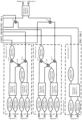
- FIG. 6b shows an 8-input-64-output communication apparatus in which 8-channel input signals are divided into multi-channel signals by using a power splitter and the multi-channel signals are input to 32 8-input-2-output (constructed by two first structures 1 -0 (4-input-2-output)) units.
- phase difference values of four phase difference couplers (two first phase difference couplers 1-0-1 and two second phase difference coupler 1-0-2) of each 8-input-2-output unit and phase shift values of phase shifters (two first phase shifters 1-0-3 and two second phase shifters 1-0-4) are the same respectively. Specific values are determined based on directions of required beams.
- Eight phase shifters coupled to input ports of phase difference couplers in the 8-input-2-output unit shown in FIG. 6a may be configured to adjust initial phases corresponding to eight beams corresponding to different 8-input-2-output units.
- FIG. 6b shows a unit arrangement of same two-dimensional antenna arrays.
- PD 1_column and PD 1_row are respectively a phase difference in input signals between adjacent columns and a phase difference in input signals between adjacent rows that are required by a radiation beam 1 of an antenna array shown in FIG. 6b .
- PD 2_column and PD 2_row are respectively a phase difference in input signals between adjacent columns and a phase difference in input signals between adjacent rows that are required by a radiation beam 2 of an antenna array shown in FIG. 6b .
- PD 3_column and PD 3_row are respectively a phase difference in input signals between adjacent columns and a phase difference in input signals between adjacent rows that are required by a radiation beam 3 of an antenna array shown in FIG. 6b .
- PD 4_column and PD 4_row are respectively a phase difference in input signals between adjacent columns and a phase difference in input signals between adjacent rows that are required by a radiation beam 4 of an antenna array shown in FIG. 6b .
- PD 5_column and PD 5_row are respectively a phase difference in input signals between adjacent columns and a phase difference in input signals between adjacent rows that are required by a radiation beam 5 of an antenna array shown in FIG. 6b .
- PD 6_column and PD 6_row are respectively a phase difference in input signals between adjacent columns and a phase difference in input signals between adjacent rows that are required by a radiation beam 6 of an antenna array shown in FIG. 6b .
- PD 7_column and PD 7_row are respectively a phase difference in input signals between adjacent columns and a phase difference in input signals between adjacent rows that are required by a radiation beam 7 of an antenna array shown in FIG. 6b .
- PD 8_column and PD 8_row are respectively a phase difference in input signals between adjacent columns and a phase difference in input signals between adjacent rows that are required by a radiation beam 8 of an antenna array shown in FIG. 6b .
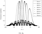
- the communication apparatus shown in FIG. 6b may generate, by connecting to 8 ⁇ 8 two-dimensional antenna arrays, eight beams that can be independently adjusted.
- a spacing is a half wavelength
- ⁇ is an azimuth of a spherical coordinate
- ⁇ 4 16°
- ⁇ 5 -16°
- ⁇ 6 27°
- ⁇ 7 0°
- ⁇ 8 46°
- ⁇ is a pitch angle of a spherical coordinate
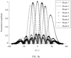
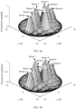
- FIG. 7a there are eight wave peaks. That is, correspondingly, the eight beams in FIG. 7b are a beam 1, a beam 2, a beam 3, a beam 4, a beam 5, a beam 6, a beam 7, and a beam 8 respectively.
- the communication apparatus may independently adjust a direction of each beam.
- the beam 1 is used as an example.
- FIG. 8a to FIG. 8d show that the beam 1 implements independent scanning in an x direction without affecting other seven beams.
- FIG. 9a and FIG. 9b show schematic diagrams of independent scanning by the beam 7 in a y direction.
- a fifth combiner 7, a sixth combiner 8, a seventh combiner 9, an eighth combiner 10, a fourth phase difference coupler 11, and a fifth phase difference coupler 12 are further introduced to further reduce a quantity of phase shifters required by the communication apparatus, as shown in FIG. 10a-1 and FIG. 10a-2 .
- the fifth combiner 7 may combine a signal from an output port of the first phase shifter 1-0-3 in an odd-numbered first structure 1-0, and an output port of the fifth combiner 7 is coupled to a first input port of the fourth phase difference coupler 11;
- the sixth combiner 8 may combine a signal from an output port of the second combiner 1-0-11 in an odd-numbered first structure 1-0, and an output port of the sixth combiner 8 is coupled to a first input port of the fifth phase difference coupler 12;
- the seventh combiner 9 may combine a signal from an output port of the first phase shifters 1-0-3 in an even-numbered first structure 1-0, and an output port of the seventh combiner 9 is coupled to a second input port of the fourth phase difference coupler 11;
- the eighth combiner 10 may combine a signal from an output port of the second combiner 1-0-11 in an even-numbered first structure 1-0, and an output port of the eighth combiner 10 is coupled to a second input port of the fifth phase difference coupler 12.
- the fifth combiner 7 may combine a signal from an output port of the first phase shifter 1-0-3 in an odd-numbered first structure 1-0 and a signal from an output port of the seventh phase shifter 1-1-2 in the second structure 1-1, and the output port of the fifth combiner 7 is coupled to the first input port of the fourth phase difference coupler 11;
- the sixth combiner 8 may combine a signal from an output port of the second combiner 1-0-11 in an odd-numbered first structure 1-0 and a signal from a second output port of the third phase difference coupler 1-1-1 in the second structure 1-1, and the output port of the sixth combiner 8 is coupled to the first input port of the fifth phase difference coupler 12;
- the seventh combiner 9 may combine a signal from an output port of the first phase shifter 1-0-3 in an even-numbered first structure 1-0, and the output port of the seventh combiner 9 is coupled to the second input port of
- the fifth combiner 7 may combine a signal from an output port of the first phase shifter 1-0-3 in an odd-numbered first structure 1-0 and a signal from an output port of the tenth phase shifter 1-2-2 in the third structure 1-2, and the output port of the fifth combiner 7 is coupled to the first input port of the fourth phase difference coupler 11;
- the sixth combiner 8 may combine a signal from an output port of the second combiner 1-0-11 in an odd-numbered first structure 1-0 and a signal from a second output port of the power splitter 1-2-1 in the third structure 1-2, and the output port of the sixth combiner 8 is coupled to the first input port of the fifth phase difference coupler 12;
- the seventh combiner 9 may combine a signal from an output port of the first phase shifter 1-0-3 in an even-numbered first structure 1-0, and the output port of the seventh combiner 9 is coupled to the second input port of the
- phase shift unit 1 includes a plurality of first structures 1-0 that are sorted in turn, for example, 10 first structures 1-0, the foregoing odd-numbered may be understood as a first, third, fifth, seventh, and ninth, and the foregoing even-numbered may be understood as a second, a fourth, a sixth, an eighth, and a tenth.
- the fourth phase difference coupler 11 and the fifth phase difference coupler 12 are introduced to increase a quantity of output ports of the communication apparatus, so that a quantity of phase shifters in the communication apparatus can be further reduced.
- phase difference values of phase difference couplers and phase shift values of phase shifters in an 8-input-2-output unit may be set based on phase difference values of phase difference couplers and phase shift values of phase shifters corresponding to the beams in FIG. 7a , and eight beams in spatial distribution may be obtained. Scanning by the eight beams in an x direction is completely the same as that of FIG. 7a , that is, the eight beams may perform scanning independently and freely in the x direction. However, the eight beams perform scanning independently in two groups in a y direction.
- Beams 1 to 4 form a group, and beams 5 to 8 form a group.
- scanning by the beams in the y direction is implemented by adjusting values of the phase difference couplers x 4 and x 5 .
- a signal combination manner is not limited to the foregoing signal combination manner. Another signal combination manner may be further included. This is not specifically limited herein in this application.
- the fifth combiner 7 may combine signals from output ports of first phase shifters 1-0-3 of a first structure to an n th structure
- the sixth combiner 8 may combine signals from output ports of second combiners 1-0-11 of a first first structure to an n th first structure 1-0
- the seventh combiner 9 may combine signals from output ports of first phase shifters 1-0-3 of an n +1 th first structure to a 2 n th first structure 1-0
- the eighth combiner 10 may combine signals from output ports of second combiners 1-0-11 of an n +1 th first structure to a 2 n th first structure 1-0.
- n is an integer, and n is greater than or equal to 0. Any manner in which output signals of the phase shift unit 1 are combined by using the fifth combiner 7, the sixth combiner 8, the seventh combiner 9, and the eighth combiner 10 is applicable to this application.
- the communication apparatus may further include a controller 4, as shown in FIG. 12 .
- the controller 4 is coupled to the phase shift unit 1.
- the controller 4 may determine, in the foregoing manner, phase shift values of phase shifters and phase difference values of phase difference couplers in the communication apparatus, and adjust a parameter of the phase shift unit 1 based on the determined phase shift values and phase difference values.
- the parameter includes but is not limited to a parameter of at least one of the following: a parameter of the first phase difference coupler 1-0-1, a parameter of the second phase difference coupler 1-0-2, a parameter of the third phase difference coupler 1-1-1, a parameter of the first phase shifter 1-0-3, a parameter of the second phase shifter 1-0-4, a parameter of the third phase shifter 1-0-5, a parameter of the fourth phase shifter 1-0-6, a parameter of the fifth phase shifter 1-0-7, a parameter of the sixth phase shifter 1-0-8, a parameter of the seventh phase shifter 1-1-2, a parameter of the eighth phase shifter 1-1-3, a parameter of the ninth phase shifter 1-1-4, a parameter of the tenth phase shifter 1-2-2, and a parameter of the eleventh phase shifter 1-2-3.
- controller 4 may be implemented by using a field programmable gate array (field programmable gate array, FPGA) or a digital signal processing (digital signal processing, DSP) chip, or may be implemented in another hardware manner or software manner. This is not specifically limited herein in this application.
- FPGA field programmable gate array
- DSP digital signal processing
- phase difference coupler in this application may implement a phase difference coupler with an adjustable phase difference by using a single-pole multi-throw switch, a phase difference coupler with a fixed phase difference, and a phase shifter with a fixed phase shift value.
- FIG. 13 shows a specific structure of a phase difference coupler with an adjustable phase difference. An adjustment range of the phase difference value of the phase difference coupler having the structure is from 0° to 180° (including 0° and 180°), and an adjustment step is 22.5°. As shown in FIG.
- the structure includes two single-pole eight-throw switches A and B, four 3 dB phase difference couplers with a phase difference of -45°, four 3 dB phase difference couplers with a phase difference of 45°, 16 fixed phase shifters, an output port C, and an output port D. Distribution of phase shift values of the phase shifters is also shown in FIG. 13 .
- phase difference couplers with different phase difference values are implemented by selecting different input ports through the switches.
- Correspondences of phase differences between input ports and output ports are shown in Table 1. In actual application, only some rows or columns in Table 1 may be applied, which is not specifically limited herein.
- a phase difference value of an adjustable phase difference coupler determined through the structure is -22.5. If the single-pole multi-throw switch A is connected to an input port d , and the single-pole multi-throw switch B is connected to an input port l , a phase difference value of an adjustable phase difference coupler determined through the structure is -45.
- Table 3 Correspondences of phase differences between input ports and output ports of adjustable phase difference couplers shown in FIG.
- Phase difference of a phase difference coupler (:°) Connected port number Phase difference between an output port C and an output port D (:°) -22.5 Input port A b -22.5 Input port B j 22.5 -45 Input port A d -45 Input port B l 45 -67.5 Input port A f -67.5 Input port B n 67.5 -90 Input port A h -90 Input port B p 90 -112.5 Input port A a -112.5 Input port B i 112.5 -135 Input port A b -135 Input port B k 135 -157.5 Input port A c -157.5 Input port B m 157.5 -180 Input port A e -180 Input port B o 180
- the phase difference coupler with the adjustable phase difference is introduced, so that a quantity of phase shifters required during beamforming can be reduced.
- Signals in different channels may share the first phase shifter 1-0-3 and the second phase shifter 1-0-4.
- the quantity of the phase shifters can also be reduced, device overheads during beamforming can be reduced, and power consumption of the device can be further reduced.
- a phase difference value of the phase difference coupler and a phase shift value of the phase shifter are adjusted, so that a plurality of beams can be flexibly adjusted and controlled, and independent scanning by each beam can be implemented.
- this application may be provided as a method, a system, or a computer program product. Therefore, this application may use a form of hardware only embodiments, software only embodiments, or embodiments with a combination of software and hardware. In addition, this application may use a form of a computer program product that is implemented on one or more computer-usable storage media (including but not limited to a disk memory, a CD-ROM, an optical memory, and the like) that include computer-usable program code.
- computer-usable storage media including but not limited to a disk memory, a CD-ROM, an optical memory, and the like
- the computer program instructions may be provided for a general-purpose computer, a dedicated computer, an embedded processor, or a processor of any other programmable data processing device to generate a machine, so that the instructions executed by a computer or a processor of any other programmable data processing device generate an apparatus for implementing a specific function in one or more processes in the flowcharts and/or in one or more blocks in the block diagrams.
- the computer program instructions may alternatively be stored in a computer-readable memory that can indicate a computer or any other programmable data processing device to work in a specific manner, so that the instructions stored in the computer-readable memory generate an artifact that includes an instruction apparatus.
- the instruction apparatus implements a specific function in one or more processes in the flowcharts and/or in one or more blocks in the block diagrams.
- the computer program instructions may alternatively be loaded onto a computer or another programmable data processing device, so that a series of operations and steps are performed on the computer or the another programmable device, to generate computer-implemented processing. Therefore, the instructions executed on the computer or the another programmable device provide steps for implementing a specific function in one or more processes in the flowcharts and/or in one or more blocks in the block diagrams.
Landscapes
- Engineering & Computer Science (AREA)
- Computer Networks & Wireless Communication (AREA)
- Signal Processing (AREA)
- Variable-Direction Aerials And Aerial Arrays (AREA)
Applications Claiming Priority (2)
| Application Number | Priority Date | Filing Date | Title |
|---|---|---|---|
| CN202010959909.5A CN114188680A (zh) | 2020-09-14 | 2020-09-14 | 一种通信装置及系统 |
| PCT/CN2021/113649 WO2022052783A1 (fr) | 2020-09-14 | 2021-08-19 | Appareil et système de communication |
Publications (2)
| Publication Number | Publication Date |
|---|---|
| EP4199242A1 true EP4199242A1 (fr) | 2023-06-21 |
| EP4199242A4 EP4199242A4 (fr) | 2024-02-21 |
Family
ID=80538944
Family Applications (1)
| Application Number | Title | Priority Date | Filing Date |
|---|---|---|---|
| EP21865839.1A Pending EP4199242A4 (fr) | 2020-09-14 | 2021-08-19 | Appareil et système de communication |
Country Status (5)
| Country | Link |
|---|---|
| US (1) | US12316019B2 (fr) |
| EP (1) | EP4199242A4 (fr) |
| JP (1) | JP7581494B2 (fr) |
| CN (1) | CN114188680A (fr) |
| WO (1) | WO2022052783A1 (fr) |
Families Citing this family (2)
| Publication number | Priority date | Publication date | Assignee | Title |
|---|---|---|---|---|
| AU2022303016A1 (en) * | 2021-06-29 | 2024-01-25 | Viasat, Inc. | Communication performance mapping for phased array antennas |
| CN115632241B (zh) * | 2022-10-31 | 2023-05-30 | 成都华芯天微科技有限公司 | 一种低轨卫星通信星载多波束相控阵天线 |
Family Cites Families (23)
| Publication number | Priority date | Publication date | Assignee | Title |
|---|---|---|---|---|
| US7272364B2 (en) * | 2002-12-30 | 2007-09-18 | Motorola, Inc. | Method and system for minimizing overlap nulling in switched beams |
| US8013784B2 (en) * | 2009-03-03 | 2011-09-06 | Toyota Motor Engineering & Manufacturing North America, Inc. | Butler matrix for 3D integrated RF front-ends |
| US8289209B2 (en) | 2009-04-13 | 2012-10-16 | Viasat, Inc. | Active butler and blass matrices |
| CN102480330B (zh) * | 2010-11-25 | 2014-05-28 | 大唐移动通信设备有限公司 | 一种基站智能天线广播赋形的测试方法及设备 |
| CN102509891B (zh) * | 2011-10-27 | 2014-06-18 | 电子科技大学 | 频率可调的巴特勒矩阵 |
| CN102610920B (zh) * | 2012-03-22 | 2014-12-24 | 中国联合网络通信集团有限公司 | 天馈系统和相位校准方法 |
| TWI518993B (zh) * | 2012-11-20 | 2016-01-21 | 財團法人工業技術研究院 | 具可調式相移陣列的多路徑切換系統 |
| EP3024297B1 (fr) * | 2013-07-12 | 2020-10-14 | Guangdong Broadradio Communication Technology Co. Ltd. | Matrice de butler 3×3 et matrice de butler 5×6 |
| CN103682682B (zh) | 2013-11-27 | 2016-08-17 | 华为技术有限公司 | 一种多波束天线系统 |
| US10374308B2 (en) * | 2014-04-04 | 2019-08-06 | Telefonaktiebolaget Lm Ericsson (Publ) | Signal distribution network |
| CN106663871B (zh) * | 2014-11-19 | 2020-03-10 | 华为技术有限公司 | 相位校准方法和装置 |
| CN104901019B (zh) * | 2015-04-30 | 2018-05-22 | 北京航天光华电子技术有限公司 | 一种有源极化控制器 |
| US9972893B2 (en) * | 2015-12-29 | 2018-05-15 | Commscope Technologies Llc | Duplexed phased array antennas |
| CN106229685B (zh) | 2016-09-22 | 2023-03-31 | 京信通信技术(广州)有限公司 | 波束成形网络及双极化五波束天线 |
| KR101809383B1 (ko) | 2016-12-19 | 2017-12-14 | 전자부품연구원 | 하이브리드 버틀러 매트릭스 및 이를 이용한 통신장치 |
| JP7088631B2 (ja) * | 2017-03-06 | 2022-06-21 | 株式会社Nttドコモ | 送受信装置 |
| US11082102B2 (en) * | 2017-09-28 | 2021-08-03 | Hitachi Kokusai Electric Inc. | Beam forming antenna |
| KR102405672B1 (ko) * | 2017-11-06 | 2022-06-03 | 엘지디스플레이 주식회사 | Dgs를 포함하는 위상 천이기 및 이를 포함하는 전파 통신 모듈 |
| EP3742551A4 (fr) * | 2018-02-22 | 2020-12-30 | Mitsubishi Electric Corporation | Dispositif d'antenne et dispositif de communication sans fil |
| CN110391829B (zh) | 2018-04-20 | 2021-05-11 | 上海华为技术有限公司 | 馈电信号形成方法及其相关设备 |
| WO2020150178A1 (fr) * | 2019-01-17 | 2020-07-23 | Avx Antenna, Inc. D/B/A Ethertronics, Inc. | Déphaseur de fréquence radio à ondes millimétriques |
| CN210123797U (zh) * | 2019-06-12 | 2020-03-03 | 中国移动通信有限公司研究院 | 一种天线阵列 |
| US11082186B2 (en) * | 2019-09-25 | 2021-08-03 | Raytheon Company | Phased array antenna system |
-
2020
- 2020-09-14 CN CN202010959909.5A patent/CN114188680A/zh active Pending
-
2021
- 2021-08-19 WO PCT/CN2021/113649 patent/WO2022052783A1/fr not_active Ceased
- 2021-08-19 JP JP2023516561A patent/JP7581494B2/ja active Active
- 2021-08-19 EP EP21865839.1A patent/EP4199242A4/fr active Pending
-
2023
- 2023-03-09 US US18/180,881 patent/US12316019B2/en active Active
Also Published As
| Publication number | Publication date |
|---|---|
| JP7581494B2 (ja) | 2024-11-12 |
| US12316019B2 (en) | 2025-05-27 |
| WO2022052783A1 (fr) | 2022-03-17 |
| CN114188680A (zh) | 2022-03-15 |
| JP2023541913A (ja) | 2023-10-04 |
| US20230223685A1 (en) | 2023-07-13 |
| EP4199242A4 (fr) | 2024-02-21 |
Similar Documents
| Publication | Publication Date | Title |
|---|---|---|
| EP2685557B1 (fr) | Antenne et station de base | |
| JP6903155B2 (ja) | アンテナシステム、信号処理システム、および信号処理方法 | |
| EP2436084B1 (fr) | Agencement amélioré d'antennes | |
| US12316019B2 (en) | Communication apparatus and system | |
| US10637587B2 (en) | Communications apparatus and wireless communications device | |
| US20180138592A1 (en) | Multi-beam antenna arrangement | |
| US12451601B2 (en) | Circuit and system apparatus for synthesizing one or multiple beams on a switched-feed antenna | |
| US6522897B1 (en) | RF radiation pattern synthesis using existing linear amplifiers | |
| EP3472942B1 (fr) | Architecture analogique flexible pour sectorisation | |
| BG64659B1 (bg) | Метод за сканиране на антенна решетка и фазорегулиращо устройство за осъществяването му | |
| US10594031B1 (en) | Radio frequency integrated circuit feed manifold for active electronically scanned array | |
| EP1784893A1 (fr) | Emission et reception de signaux a radiofrequences utilisant un reseau actif balaye electroniquement | |
| US7126532B2 (en) | Apparatus for tracing an optimal direction to receive satellite signal in active phase array antenna system | |
| US7741997B1 (en) | Multiple-beam phased array with switchable element areas | |
| JPS62203403A (ja) | アレイアンテナの給電回路 | |
| EP1602149A2 (fr) | Systemes et procedes permettant d'assurer des voies de transmission independantes dans une antenne en reseau monophasee | |
| JP3637808B2 (ja) | マルチビームアンテナ | |
| JP7832860B2 (ja) | 高周波装置用アンテナアレイ | |
| WO2019201142A1 (fr) | Procédé de formation de signal d'alimentation et appareil associé | |
| WO2013028060A1 (fr) | Antenne pour produire de multiples faisceaux et procédé associé | |
| CN115833893A (zh) | 一种多通道偏馈信号检测与合成网络的设计方法 | |
| JP6540431B2 (ja) | アンテナ装置、およびその制御方法 | |
| RU2541186C1 (ru) | Двумерная моноимпульсная фар с электронным управлением лучом | |
| JPH06196922A (ja) | フェーズドアレー用給電回路 |
Legal Events
| Date | Code | Title | Description |
|---|---|---|---|
| STAA | Information on the status of an ep patent application or granted ep patent |
Free format text: STATUS: THE INTERNATIONAL PUBLICATION HAS BEEN MADE |
|
| PUAI | Public reference made under article 153(3) epc to a published international application that has entered the european phase |
Free format text: ORIGINAL CODE: 0009012 |
|
| STAA | Information on the status of an ep patent application or granted ep patent |
Free format text: STATUS: REQUEST FOR EXAMINATION WAS MADE |
|
| 17P | Request for examination filed |
Effective date: 20230317 |
|
| AK | Designated contracting states |
Kind code of ref document: A1 Designated state(s): AL AT BE BG CH CY CZ DE DK EE ES FI FR GB GR HR HU IE IS IT LI LT LU LV MC MK MT NL NO PL PT RO RS SE SI SK SM TR |
|
| DAV | Request for validation of the european patent (deleted) | ||
| DAX | Request for extension of the european patent (deleted) | ||
| REG | Reference to a national code |
Ref country code: DE Ref legal event code: R079 Free format text: PREVIOUS MAIN CLASS: H01P0001180000 Ipc: H01Q0003400000 |
|
| A4 | Supplementary search report drawn up and despatched |
Effective date: 20240122 |
|
| RIC1 | Information provided on ipc code assigned before grant |
Ipc: H01Q 3/40 20060101AFI20240116BHEP |