EP4199271A1 - Dispositif de retenue pour dispositifs de mise en contact - Google Patents
Dispositif de retenue pour dispositifs de mise en contact Download PDFInfo
- Publication number
- EP4199271A1 EP4199271A1 EP22214585.6A EP22214585A EP4199271A1 EP 4199271 A1 EP4199271 A1 EP 4199271A1 EP 22214585 A EP22214585 A EP 22214585A EP 4199271 A1 EP4199271 A1 EP 4199271A1
- Authority
- EP
- European Patent Office
- Prior art keywords
- contacting
- blocking
- blocking element
- contacting device
- support profile
- Prior art date
- Legal status (The legal status is an assumption and is not a legal conclusion. Google has not performed a legal analysis and makes no representation as to the accuracy of the status listed.)
- Granted
Links
Images


Classifications
-
- H—ELECTRICITY
- H01—ELECTRIC ELEMENTS
- H01R—ELECTRICALLY-CONDUCTIVE CONNECTIONS; STRUCTURAL ASSOCIATIONS OF A PLURALITY OF MUTUALLY-INSULATED ELECTRICAL CONNECTING ELEMENTS; COUPLING DEVICES; CURRENT COLLECTORS
- H01R13/00—Details of coupling devices of the kinds covered by groups H01R12/70 or H01R24/00 - H01R33/00
- H01R13/62—Means for facilitating engagement or disengagement of coupling parts or for holding them in engagement
- H01R13/639—Additional means for holding or locking coupling parts together, after engagement, e.g. separate keylock, retainer strap
-
- H—ELECTRICITY
- H01—ELECTRIC ELEMENTS
- H01R—ELECTRICALLY-CONDUCTIVE CONNECTIONS; STRUCTURAL ASSOCIATIONS OF A PLURALITY OF MUTUALLY-INSULATED ELECTRICAL CONNECTING ELEMENTS; COUPLING DEVICES; CURRENT COLLECTORS
- H01R13/00—Details of coupling devices of the kinds covered by groups H01R12/70 or H01R24/00 - H01R33/00
- H01R13/62—Means for facilitating engagement or disengagement of coupling parts or for holding them in engagement
- H01R13/627—Snap or like fastening
- H01R13/6275—Latching arms not integral with the housing
-
- H—ELECTRICITY
- H01—ELECTRIC ELEMENTS
- H01R—ELECTRICALLY-CONDUCTIVE CONNECTIONS; STRUCTURAL ASSOCIATIONS OF A PLURALITY OF MUTUALLY-INSULATED ELECTRICAL CONNECTING ELEMENTS; COUPLING DEVICES; CURRENT COLLECTORS
- H01R25/00—Coupling parts adapted for simultaneous co-operation with two or more identical counterparts, e.g. for distributing energy to two or more circuits
- H01R25/14—Rails or bus-bars constructed so that the counterparts can be connected thereto at any point along their length
- H01R25/142—Their counterparts
Definitions
- the invention relates to a method for fastening a contacting device in a support profile and a contacting device for use in a support profile, the contacting device having a holding device with a number of retaining clips which engage behind an undercut of the support profile.
- Such systems generally relate to linear current distribution arrangements which are used in particular for lighting systems in buildings in order to lay lines for supplying devices with energy and/or signals in a cost-effective and visually appealing manner.
- Signals are understood to mean both the transmission of general signals, such as control signals, and the transmission of data, such as measurement or information data.
- the installation location of the devices can be chosen flexibly along a housing body of the power distribution arrangement and easily varied.
- the devices can thus be electrically conductively contacted with the conductors of a linear supply unit at a variably definable installation location using a contacting element.
- Such current distribution arrangements have the advantage that the devices are carried on the housing body both in an electrically contacting manner and also mechanically at the same time.
- the contacting devices within the meaning of these applications include both feeders, i.e. assemblies that feed corresponding signals and/or energy into the conductors to be contacted, but also taps that tap the corresponding signals and/or energy from the contacting conductors and feed them to external terminals.
- Linear power supply units which are mounted in a housing body, are usually used in the linear current distribution arrangements for distributing or forwarding the energy or signals.
- These supply units can, for example, be in the form of current-carrying profiles, but also in the form of ribbon cables.
- the current-carrying profiles are formed from a base body which extends in the longitudinal direction and has a number of chambers in which individual conductors are arranged.
- These current-carrying profiles are generally rigid and have a limited length due to the manufacturing process.
- For longer current distribution arrangements such as those used in larger factory buildings or warehouses, for example, several current-carrying profiles are usually required, which are then connected to one another both mechanically and electrically via a connecting element. Also at the When using ribbon cables, depending on the length of the ribbon cable, connecting elements can be used.
- Rigid round conductors are usually used as conductors, which are used or inserted into the chambers.
- a contacting device with a number of contact elements which acts as a tap, then engages in these chambers and contacts the contact elements with the corresponding conductors, as a result of which the signals or energy can be routed from the conductors to the terminal devices via the taps. Conversely, this also applies to corresponding feeders.
- the contacting device For reliable, permanent and sufficient contacting of the conductors by the contact elements, it is important that the contacting device is held firmly in the support profiles. It must be taken into account that the contacting devices are sometimes only installed directly on site, i.e. at the end customer's site, in the support profiles and may have to be relocated or replaced later.
- Fastening device for contacting devices in linear current distribution arrangements are in particular from the publications DE 10 2013 216 275 A1 , DE 10 2019 109 676 A1 , DE 20 2008 001 961 U1 , DE 20 2018 100 522 U1 known.
- the object of the invention is therefore to specify a particularly secure holder for contacting devices so that they can be easily assembled and, if necessary, disassembled again.
- the task is based on the consideration that common holding devices, which only engage in an undercut of a support profile, do not guarantee sufficient support, since the holding clamps can become detached from the undercuts on their own as a result of tensile forces on the connected conductors or the weight of the components themselves. which would lead to an interruption of the electrical contact.
- the holding elements are locked in position in such a way that they can no longer be independently pushed or pushed out of the undercuts.
- a blocking element is provided, which engages or grips behind the retaining clips, so that a movement of the retaining clips in the transverse direction, ie out of the undercuts, is prevented.
- the blocking element is also designed to be able to be moved between an open and a blocked position in the contacting direction, the movement of the retaining clips in the transverse direction in the area of the undercut being blocked only in the blocked position.
- the blocking element advantageously latches behind a projection of the support profile after it has been moved into the blocking position.
- the holding device in a preferred embodiment comprises two holding elements on two opposite sides of the contacting device, with a blocking element being arranged between the two holding elements on each side.
- the blocking element is designed in an advantageous embodiment with a number of blocking wings which protrude laterally from the blocking element and engage behind the retaining clips. When the blocking element is displaced, these blocking wings are thus guided along behind the retaining clips and, in the blocking position, lie behind the retaining clips in the region of the undercut.
- the blocking element For the dismantling it is necessary that the blocking element can be brought back into the open position. To do this, however, the latching of the blocking element must be released behind the second projection of the support profile. In order to make this particularly easy, the blocking element has a release device which releases this latching and then moves the blocking element into the open position.
- the blocking element achieves double securing of the contacting device in a support profile.
- the supporting profile in its blocked position ensures that the retaining clips do not fall out of the undercuts and, on the other hand, the blocking element itself is fixed in the supporting profile in the blocked position, so that an undesired displacement of the blocking element into the open position is avoided.
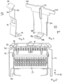
- the contacting device 1 comprises a contacting housing 2, in which a number of contact assemblies 4 are arranged.
- the contact assemblies 4 are arranged one behind the other in the transverse direction Q and can be mounted in the contact housing 2 both individually and in combination.
- the contact assemblies 4 include contact elements 6, which protrude from the contacting housing 2 of the contacting device 1 in the contacting direction K, and can be contacted with conductors 8, for example a linear power supply device.
- the contact assemblies 4 include connection devices provided on both sides for external conductors, which can be electrically connected to the conductors 8 of the linear power supply device via the contact assemblies 4 .
- the connection devices comprise insertion openings 10 formed in the longitudinal direction for receiving the external conductors.
- the contacting device 1 also includes a holding device 12, which in the exemplary embodiment shown here is arranged laterally, i.e. in front of and behind the contact assemblies 4 in the transverse direction Q, and enables the contacting device 1 to be fixed in a corresponding receptacle, for example in a support profile 14 .
- the holding device 12 according to the embodiment of figure 1 comprises two spaced-apart retaining clips 16 on each side.
- Each of the retaining clips 16 includes a base section 18, which grips under the contacting device 1 and thus supports the contacting device 1, a middle section 20, which runs along the lateral surface of the contacting housing 1 from the bottom to the top of the contacting housing 2 and together with the opposite retaining clip 16 on the other opposite lateral surface, the contacting device 1 is fixed in the transverse direction Q and a fixing section 22, which extends from the middle section and above the contacting housing essentially in the contacting direction K extends.
- This fixing section 22 is designed to engage and latch in an undercut 24 of the receiving device, in particular of a support profile 14 .
- it has a holding platform 26 which extends in the transverse direction Q and thus bends approximately perpendicularly from the extension of the middle section 20 .
- the fixing section 22 also has an insertion bevel 28, which protrudes from the holding platform 26 at an angle of less than 90°, preferably in the range of about 45°.
- This insertion bevel 28 allows the holding platform 26 to be guided past a corresponding projection 30 of the support profile 14 when the contacting device 1 is inserted and then to snap into the undercut 24 of the support profile 14 behind the projection 30 .
- the retaining clip 16 is individually in figure 3 enlarged again.
- the holding device 12 according to the embodiment according to the Figure 1 and Figure 2 also has a blocking element 32 on each side, which is arranged in the longitudinal direction L between the two retaining clips 16 in the embodiment shown there.
- the blocking element 32 is designed in such a way that it can be displaced in the contacting direction K between a first open position and a second blocking position. In the embodiment after Figure 1 and Figure 2 the blocking element 32 is shown in the open position.
- the blocking element 32 comprises a base body 34, which runs essentially in the contacting direction K, but is designed to taper slightly in the transverse direction Q in the contacting direction K.
- the thickness of the base body 34 in the transverse direction Q is thus thinner at the upper end, that is to say the end which in the installed state faces the conductors 12 to be contacted, than at the lower end. This leads to a supporting edge 36 being formed at the lower end of the base body.
- a release device 38 also extends in the transverse direction Q at the lower end of the base body 34 and is oriented in such a way that it runs under the contacting housing 2 .
- the base body 34 comprises two blocking wings 40, which protrude laterally on both sides in the longitudinal direction L from the base body 34. Depending on their position, these blocking wings 40 engage behind the fixing section 22 of the retaining clips 16.
- the blocking element 32 is shown individually in FIG figure 4 shown again.
- a curvature of the base body 34 can be clearly seen in the lower area, which provides the change in the thickness of the base body 34 described above.
- the base body 34 is hollow on the inside in this area, which means that the base body 34 acts like a leaf spring in the lower area, which is compressed when it is moved from the open to the closed position, as will be described in more detail below.
- the guide slot 42 of the blocking element 32 can be seen, which allows a guided displacement of the blocking element 32 within the limits set by the guide slot 42, ie from the open to the blocking position.
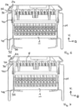
- FIG. 5 An exemplary inclusion of a contacting device in a support profile 14 is shown in figure 5 shown in front view.
- the support profile 14 comprises a linear current guide, which consists of a comb-like current guide profile 44, with a conductor 8 being inserted in each chamber.
- the contact assemblies 4 in the contacting device 1 are arranged next to one another at a distance from one another in such a way that each contact assembly 4 is assigned a conductor 8 and thus each contact assembly 4 can contact a conductor 8 .
- the contacting device 1 after figure 5 is not yet fixed in the support profile 14, but is just about to be pushed into the support profile 14.
- the holding platform 26 of the fixing section 22 of the holding clamps 16 has been guided past the projections 30 due to the insertion bevel 28 and is thereby deflected in the transverse direction Q to the center of the contacting device 1 .
- the blocking element is pushed from the open position into the blocking position, as is shown in figure 7 is shown. This is done by pushing the blocking element 32 upwards in the contacting direction K in the direction of the conductor 8 .
- the blocking effect is created in two ways. First, the blocking wings 40 in the fixing section 22 are pushed into the area of the holding platform 26, so that the holding platform 26 can no longer shift in the transverse direction Q, even under the action of force, since the blocking wings 40 block this path.
- the area of the lower base body 34 has the form and function of a leaf spring, which is compressed when the blocking element 32 is moved past the second projection 48 of the support profile 14 and then returns to its arched configuration in order to form a supporting edge 36 for the blocking element 32 .
- the flexibility required for snapping is ensured in part by the support profile 14 and the blocking element 32 itself.
- the contacting element 1 is thus now doubly fixed, namely at the top and bottom in the support profile 14 .
- a contacting element 1 with a blocking element 32 in the blocking position is in the exemplary embodiment according to FIG figure 8 shown again without the support profile 14.
- the blocking wings 40 which engage behind the retaining clips 16 in the area of the retaining platform 26 and prevent a transverse movement in the direction of the center of the contacting device 1, can be clearly seen.
- the contacting element 1 is shown with a blocking element 32 in the blocking position from below in order to clarify the release device 38 .
- the release device 38 includes a release eyelet 50 and, with an external tool that engages in the release eyelet 50 , enables the release device 38 to be pushed in the transverse direction Q towards the center of the contacting device 1 .
- the release device 38 is arranged centrally in the longitudinal direction L, so that it engages directly on the lower area of the base body 34, which is designed as a leaf spring, and can guide the leaf spring and thus the entire base body 34 past the second projection 48 of the support profile.
- the blocking element 32 is pulled out of the projection 48 of the support profile 14 in the region of the support edge 36 and freed, so that in the next step the blocking element 32 can be transferred from the blocked position to the open position. This also releases the holding platforms 26 again. This enables the contacting device 1 to be detached from the support profile 14.
Landscapes
- Connector Housings Or Holding Contact Members (AREA)
Applications Claiming Priority (1)
| Application Number | Priority Date | Filing Date | Title |
|---|---|---|---|
| DE102021133754.2A DE102021133754A1 (de) | 2021-12-17 | 2021-12-17 | Haltevorrichtung für Kontaktierungsvorrichtungen |
Publications (3)
| Publication Number | Publication Date |
|---|---|
| EP4199271A1 true EP4199271A1 (fr) | 2023-06-21 |
| EP4199271B1 EP4199271B1 (fr) | 2025-10-29 |
| EP4199271C0 EP4199271C0 (fr) | 2025-10-29 |
Family
ID=84537999
Family Applications (1)
| Application Number | Title | Priority Date | Filing Date |
|---|---|---|---|
| EP22214585.6A Active EP4199271B1 (fr) | 2021-12-17 | 2022-12-19 | Dispositif de retenue pour dispositifs de mise en contact |
Country Status (3)
| Country | Link |
|---|---|
| EP (1) | EP4199271B1 (fr) |
| DE (1) | DE102021133754A1 (fr) |
| PL (1) | PL4199271T3 (fr) |
Citations (6)
| Publication number | Priority date | Publication date | Assignee | Title |
|---|---|---|---|---|
| DE202008001961U1 (de) | 2008-02-13 | 2008-04-17 | Ridi Leuchten Gmbh | Kontaktierungssystem für Lichtbänder oder Leuchten |
| EP2105658A1 (fr) * | 2008-03-28 | 2009-09-30 | Etap N.V. | Module pour luminaire et chassis destiné à recevoir un tel module |
| DE102013216275A1 (de) | 2013-07-15 | 2015-03-19 | Ridi Leuchten Gmbh | Leuchte |
| DE202018100522U1 (de) | 2018-01-31 | 2019-05-03 | Zumtobel Lighting Gmbh | Lichtbandsystem |
| DE102019109676A1 (de) | 2018-08-09 | 2020-02-13 | Trilux Gmbh & Co. Kg | Haltefeder für Leuchte |
| EP3653925A1 (fr) * | 2018-11-15 | 2020-05-20 | TRILUX GmbH & Co. KG | Luminaire étanchéifié |
-
2021
- 2021-12-17 DE DE102021133754.2A patent/DE102021133754A1/de active Pending
-
2022
- 2022-12-19 PL PL22214585.6T patent/PL4199271T3/pl unknown
- 2022-12-19 EP EP22214585.6A patent/EP4199271B1/fr active Active
Patent Citations (6)
| Publication number | Priority date | Publication date | Assignee | Title |
|---|---|---|---|---|
| DE202008001961U1 (de) | 2008-02-13 | 2008-04-17 | Ridi Leuchten Gmbh | Kontaktierungssystem für Lichtbänder oder Leuchten |
| EP2105658A1 (fr) * | 2008-03-28 | 2009-09-30 | Etap N.V. | Module pour luminaire et chassis destiné à recevoir un tel module |
| DE102013216275A1 (de) | 2013-07-15 | 2015-03-19 | Ridi Leuchten Gmbh | Leuchte |
| DE202018100522U1 (de) | 2018-01-31 | 2019-05-03 | Zumtobel Lighting Gmbh | Lichtbandsystem |
| DE102019109676A1 (de) | 2018-08-09 | 2020-02-13 | Trilux Gmbh & Co. Kg | Haltefeder für Leuchte |
| EP3653925A1 (fr) * | 2018-11-15 | 2020-05-20 | TRILUX GmbH & Co. KG | Luminaire étanchéifié |
Also Published As
| Publication number | Publication date |
|---|---|
| DE102021133754A1 (de) | 2023-06-22 |
| EP4199271B1 (fr) | 2025-10-29 |
| PL4199271T3 (pl) | 2026-03-23 |
| EP4199271C0 (fr) | 2025-10-29 |
Similar Documents
| Publication | Publication Date | Title |
|---|---|---|
| EP3369138B1 (fr) | Dispositif de mise en contact pour mettre en contact un conducteur électrique avec une piste conductrice | |
| DE102019127232B3 (de) | Anschlusseinrichtung zum Anschließen einer elektrischen Leitung | |
| EP3477774B1 (fr) | Connecteur du profilé d'alimentation en courant et dispositif d'alimentation en courant | |
| EP3276757B1 (fr) | Connecteur de rail de connexion et kit constitué de deux connecteurs de rail de connexion complémentaires et auges métalliques comprenant respectivement un profilé d'amenée de courant disposé en son sein | |
| DE102012011676B4 (de) | Befestigungsklemme und Baueinheit mit zwei Befestigungsklemmen und mehreren nebeneinander angeordneten Reihenklemmen | |
| DE102013110477B4 (de) | Durchführungsklemme und elektrische Baueinrichtung | |
| DE102010055789B4 (de) | Stromschienenverbinder und Stromschienensystem mit mindestens zwei benachbarten Stromschienen und einem Stromschienenverbinder | |
| EP3954007B1 (fr) | Système de jeu de barres avec au moins une barre retenue dans un boîtier de protection de contact | |
| EP3701606A1 (fr) | Système de support de câbles, partie de liaison, élément de rail conducteur, système de rails conducteurs, élément de liaison mécanique, procédé de fabrication d'un élément de rail conducteur et procédé de fabrication d'un système de rails conducteurs | |
| EP0010251A1 (fr) | Dispositif pour la fixation d'appareils d'installation | |
| EP3050166A1 (fr) | Borne de traversée | |
| DE102010040322A1 (de) | Schiebevorrichtung zur Befestigung eines Gehäuses | |
| EP3856568B1 (fr) | Raccord de dilatation pour une ligne de contact et ligne de contact | |
| EP4199271A1 (fr) | Dispositif de retenue pour dispositifs de mise en contact | |
| DE102021126225B4 (de) | Federkäfig für ein verbindungselement und verbindungselement | |
| DE102008019763B4 (de) | Baueinheit mit einer Befestigungsvorrichtung zur lösbaren rastenden Halterung eines elektrischen Verteilers | |
| EP3183779B1 (fr) | Élément de contact et connecteur | |
| EP4449563A1 (fr) | Luminaire modulaire à dispositif de contact | |
| DE102005050778B4 (de) | Kontaktgehäuse sowie elektrische Kontaktvorrichtung | |
| EP1505701A1 (fr) | Dispositif électrique à monter sur barres omnibus | |
| DE3122611C2 (de) | Verschlußkappe für elektrische Kontaktsysteme | |
| EP3772607B1 (fr) | Luminaire à prise d'atténuation | |
| EP1616371B1 (fr) | Barrette de connexion pour un ensemble de bornes destine a un petit distributeur et/ou un tableau de distribution d'une installation de distribution electrique basse tension | |
| DE102021111100B4 (de) | Anschlussvorrichtung und Verfahren zum Montieren einer solchen Anschlussvorrichtung | |
| EP3758151B1 (fr) | Agencement de borne de raccordement permettant de raccorder au moins un conducteur électrique |
Legal Events
| Date | Code | Title | Description |
|---|---|---|---|
| STAA | Information on the status of an ep patent application or granted ep patent |
Free format text: STATUS: UNKNOWN |
|
| PUAI | Public reference made under article 153(3) epc to a published international application that has entered the european phase |
Free format text: ORIGINAL CODE: 0009012 |
|
| STAA | Information on the status of an ep patent application or granted ep patent |
Free format text: STATUS: THE APPLICATION HAS BEEN PUBLISHED |
|
| AK | Designated contracting states |
Kind code of ref document: A1 Designated state(s): AL AT BE BG CH CY CZ DE DK EE ES FI FR GB GR HR HU IE IS IT LI LT LU LV MC ME MK MT NL NO PL PT RO RS SE SI SK SM TR |
|
| STAA | Information on the status of an ep patent application or granted ep patent |
Free format text: STATUS: REQUEST FOR EXAMINATION WAS MADE |
|
| 17P | Request for examination filed |
Effective date: 20231220 |
|
| RBV | Designated contracting states (corrected) |
Designated state(s): AL AT BE BG CH CY CZ DE DK EE ES FI FR GB GR HR HU IE IS IT LI LT LU LV MC ME MK MT NL NO PL PT RO RS SE SI SK SM TR |
|
| GRAP | Despatch of communication of intention to grant a patent |
Free format text: ORIGINAL CODE: EPIDOSNIGR1 |
|
| STAA | Information on the status of an ep patent application or granted ep patent |
Free format text: STATUS: GRANT OF PATENT IS INTENDED |
|
| INTG | Intention to grant announced |
Effective date: 20250522 |
|
| GRAS | Grant fee paid |
Free format text: ORIGINAL CODE: EPIDOSNIGR3 |
|
| GRAA | (expected) grant |
Free format text: ORIGINAL CODE: 0009210 |
|
| STAA | Information on the status of an ep patent application or granted ep patent |
Free format text: STATUS: THE PATENT HAS BEEN GRANTED |
|
| AK | Designated contracting states |
Kind code of ref document: B1 Designated state(s): AL AT BE BG CH CY CZ DE DK EE ES FI FR GB GR HR HU IE IS IT LI LT LU LV MC ME MK MT NL NO PL PT RO RS SE SI SK SM TR |
|
| REG | Reference to a national code |
Ref country code: CH Ref legal event code: F10 Free format text: ST27 STATUS EVENT CODE: U-0-0-F10-F00 (AS PROVIDED BY THE NATIONAL OFFICE) Effective date: 20251029 Ref country code: GB Ref legal event code: FG4D Free format text: NOT ENGLISH |
|
| REG | Reference to a national code |
Ref country code: DE Ref legal event code: R096 Ref document number: 502022005928 Country of ref document: DE |
|
| REG | Reference to a national code |
Ref country code: IE Ref legal event code: FG4D Free format text: LANGUAGE OF EP DOCUMENT: GERMAN |
|
| U01 | Request for unitary effect filed |
Effective date: 20251125 |
|
| U07 | Unitary effect registered |
Designated state(s): AT BE BG DE DK EE FI FR IT LT LU LV MT NL PT RO SE SI Effective date: 20251128 |
|
| PGFP | Annual fee paid to national office [announced via postgrant information from national office to epo] |
Ref country code: AT Payment date: 20260113 Year of fee payment: 4 |
|
| PGFP | Annual fee paid to national office [announced via postgrant information from national office to epo] |
Ref country code: TR Payment date: 20251231 Year of fee payment: 4 |
|
| U20 | Renewal fee for the european patent with unitary effect paid |
Year of fee payment: 4 Effective date: 20251231 |
|
| PG25 | Lapsed in a contracting state [announced via postgrant information from national office to epo] |
Ref country code: ES Free format text: LAPSE BECAUSE OF FAILURE TO SUBMIT A TRANSLATION OF THE DESCRIPTION OR TO PAY THE FEE WITHIN THE PRESCRIBED TIME-LIMIT Effective date: 20251029 |
|
| PG25 | Lapsed in a contracting state [announced via postgrant information from national office to epo] |
Ref country code: NO Free format text: LAPSE BECAUSE OF FAILURE TO SUBMIT A TRANSLATION OF THE DESCRIPTION OR TO PAY THE FEE WITHIN THE PRESCRIBED TIME-LIMIT Effective date: 20260129 |
|
| PG25 | Lapsed in a contracting state [announced via postgrant information from national office to epo] |
Ref country code: HR Free format text: LAPSE BECAUSE OF FAILURE TO SUBMIT A TRANSLATION OF THE DESCRIPTION OR TO PAY THE FEE WITHIN THE PRESCRIBED TIME-LIMIT Effective date: 20251029 |
|
| PG25 | Lapsed in a contracting state [announced via postgrant information from national office to epo] |
Ref country code: RS Free format text: LAPSE BECAUSE OF FAILURE TO SUBMIT A TRANSLATION OF THE DESCRIPTION OR TO PAY THE FEE WITHIN THE PRESCRIBED TIME-LIMIT Effective date: 20260129 |
|
| PG25 | Lapsed in a contracting state [announced via postgrant information from national office to epo] |
Ref country code: IS Free format text: LAPSE BECAUSE OF FAILURE TO SUBMIT A TRANSLATION OF THE DESCRIPTION OR TO PAY THE FEE WITHIN THE PRESCRIBED TIME-LIMIT Effective date: 20260228 |