EP4199295B1 - Appareil de stockage d'énergie, procédé de commande pour appareil de stockage d'énergie et système photovoltaïque - Google Patents
Appareil de stockage d'énergie, procédé de commande pour appareil de stockage d'énergie et système photovoltaïque Download PDFInfo
- Publication number
- EP4199295B1 EP4199295B1 EP22831993.5A EP22831993A EP4199295B1 EP 4199295 B1 EP4199295 B1 EP 4199295B1 EP 22831993 A EP22831993 A EP 22831993A EP 4199295 B1 EP4199295 B1 EP 4199295B1
- Authority
- EP
- European Patent Office
- Prior art keywords
- battery
- control
- energy storage
- storage apparatus
- direct current
- Prior art date
- Legal status (The legal status is an assumption and is not a legal conclusion. Google has not performed a legal analysis and makes no representation as to the accuracy of the status listed.)
- Active
Links
Images





Classifications
-
- H—ELECTRICITY
- H02—GENERATION; CONVERSION OR DISTRIBUTION OF ELECTRIC POWER
- H02J—ELECTRIC POWER NETWORKS; CIRCUIT ARRANGEMENTS OR SYSTEMS FOR SUPPLYING OR DISTRIBUTING ELECTRIC POWER; SYSTEMS FOR STORING ELECTRIC ENERGY
- H02J9/00—Circuit arrangements for emergency or stand-by power supply, e.g. for emergency lighting
- H02J9/04—Circuit arrangements for emergency or stand-by power supply, e.g. for emergency lighting in which the distribution system is disconnected from the normal source and connected to a standby source
- H02J9/06—Circuit arrangements for emergency or stand-by power supply, e.g. for emergency lighting in which the distribution system is disconnected from the normal source and connected to a standby source with automatic change-over, e.g. UPS systems
- H02J9/068—Electronic means for switching from one power supply to another power supply, e.g. to avoid parallel connection
-
- H—ELECTRICITY
- H02—GENERATION; CONVERSION OR DISTRIBUTION OF ELECTRIC POWER
- H02J—ELECTRIC POWER NETWORKS; CIRCUIT ARRANGEMENTS OR SYSTEMS FOR SUPPLYING OR DISTRIBUTING ELECTRIC POWER; SYSTEMS FOR STORING ELECTRIC ENERGY
- H02J3/00—Circuit arrangements for AC mains or AC distribution networks
- H02J3/001—Arrangements for handling faults or abnormalities, e.g. emergencies or contingencies
- H02J3/0012—Arrangements for handling faults or abnormalities, e.g. emergencies or contingencies characterised by the contingency detection means in AC networks, e.g. using phasor measurement units [PMU], synchrophasors or contingency analysis
-
- H—ELECTRICITY
- H02—GENERATION; CONVERSION OR DISTRIBUTION OF ELECTRIC POWER
- H02J—ELECTRIC POWER NETWORKS; CIRCUIT ARRANGEMENTS OR SYSTEMS FOR SUPPLYING OR DISTRIBUTING ELECTRIC POWER; SYSTEMS FOR STORING ELECTRIC ENERGY
- H02J3/00—Circuit arrangements for AC mains or AC distribution networks
- H02J3/28—Arrangements for balancing of the load in networks by storage of energy
- H02J3/32—Arrangements for balancing of the load in networks by storage of energy using batteries or super capacitors with converting means
-
- H—ELECTRICITY
- H02—GENERATION; CONVERSION OR DISTRIBUTION OF ELECTRIC POWER
- H02J—ELECTRIC POWER NETWORKS; CIRCUIT ARRANGEMENTS OR SYSTEMS FOR SUPPLYING OR DISTRIBUTING ELECTRIC POWER; SYSTEMS FOR STORING ELECTRIC ENERGY
- H02J3/00—Circuit arrangements for AC mains or AC distribution networks
- H02J3/38—Arrangements for feeding a single network from two or more generators or sources in parallel; Arrangements for feeding already energised networks from additional generators or sources in parallel
- H02J3/381—Dispersed generators
-
- H—ELECTRICITY
- H02—GENERATION; CONVERSION OR DISTRIBUTION OF ELECTRIC POWER
- H02J—ELECTRIC POWER NETWORKS; CIRCUIT ARRANGEMENTS OR SYSTEMS FOR SUPPLYING OR DISTRIBUTING ELECTRIC POWER; SYSTEMS FOR STORING ELECTRIC ENERGY
- H02J7/00—Circuit arrangements for charging or discharging batteries or for supplying loads from batteries
- H02J7/34—Parallel operation in networks using both storage and other DC sources, e.g. providing buffering
- H02J7/35—Parallel operation in networks using both storage and other DC sources, e.g. providing buffering with light sensitive cells
-
- H—ELECTRICITY
- H02—GENERATION; CONVERSION OR DISTRIBUTION OF ELECTRIC POWER
- H02J—ELECTRIC POWER NETWORKS; CIRCUIT ARRANGEMENTS OR SYSTEMS FOR SUPPLYING OR DISTRIBUTING ELECTRIC POWER; SYSTEMS FOR STORING ELECTRIC ENERGY
- H02J9/00—Circuit arrangements for emergency or stand-by power supply, e.g. for emergency lighting
- H02J9/04—Circuit arrangements for emergency or stand-by power supply, e.g. for emergency lighting in which the distribution system is disconnected from the normal source and connected to a standby source
- H02J9/06—Circuit arrangements for emergency or stand-by power supply, e.g. for emergency lighting in which the distribution system is disconnected from the normal source and connected to a standby source with automatic change-over, e.g. UPS systems
- H02J9/061—Circuit arrangements for emergency or stand-by power supply, e.g. for emergency lighting in which the distribution system is disconnected from the normal source and connected to a standby source with automatic change-over, e.g. UPS systems for DC powered loads
-
- H—ELECTRICITY
- H02—GENERATION; CONVERSION OR DISTRIBUTION OF ELECTRIC POWER
- H02J—ELECTRIC POWER NETWORKS; CIRCUIT ARRANGEMENTS OR SYSTEMS FOR SUPPLYING OR DISTRIBUTING ELECTRIC POWER; SYSTEMS FOR STORING ELECTRIC ENERGY
- H02J2101/00—Supply or distribution of decentralised, dispersed or local electric power generation
- H02J2101/20—Dispersed power generation using renewable energy sources
-
- H—ELECTRICITY
- H02—GENERATION; CONVERSION OR DISTRIBUTION OF ELECTRIC POWER
- H02J—ELECTRIC POWER NETWORKS; CIRCUIT ARRANGEMENTS OR SYSTEMS FOR SUPPLYING OR DISTRIBUTING ELECTRIC POWER; SYSTEMS FOR STORING ELECTRIC ENERGY
- H02J2101/00—Supply or distribution of decentralised, dispersed or local electric power generation
- H02J2101/20—Dispersed power generation using renewable energy sources
- H02J2101/22—Solar energy
- H02J2101/24—Photovoltaics
-
- H—ELECTRICITY
- H02—GENERATION; CONVERSION OR DISTRIBUTION OF ELECTRIC POWER
- H02J—ELECTRIC POWER NETWORKS; CIRCUIT ARRANGEMENTS OR SYSTEMS FOR SUPPLYING OR DISTRIBUTING ELECTRIC POWER; SYSTEMS FOR STORING ELECTRIC ENERGY
- H02J2101/00—Supply or distribution of decentralised, dispersed or local electric power generation
- H02J2101/20—Dispersed power generation using renewable energy sources
- H02J2101/28—Wind energy
-
- H—ELECTRICITY
- H02—GENERATION; CONVERSION OR DISTRIBUTION OF ELECTRIC POWER
- H02J—ELECTRIC POWER NETWORKS; CIRCUIT ARRANGEMENTS OR SYSTEMS FOR SUPPLYING OR DISTRIBUTING ELECTRIC POWER; SYSTEMS FOR STORING ELECTRIC ENERGY
- H02J2207/00—Details of circuit arrangements for charging or discharging batteries or supplying loads from batteries
- H02J2207/20—Charging or discharging characterised by the power electronics converter
-
- Y—GENERAL TAGGING OF NEW TECHNOLOGICAL DEVELOPMENTS; GENERAL TAGGING OF CROSS-SECTIONAL TECHNOLOGIES SPANNING OVER SEVERAL SECTIONS OF THE IPC; TECHNICAL SUBJECTS COVERED BY FORMER USPC CROSS-REFERENCE ART COLLECTIONS [XRACs] AND DIGESTS
- Y02—TECHNOLOGIES OR APPLICATIONS FOR MITIGATION OR ADAPTATION AGAINST CLIMATE CHANGE
- Y02E—REDUCTION OF GREENHOUSE GAS [GHG] EMISSIONS, RELATED TO ENERGY GENERATION, TRANSMISSION OR DISTRIBUTION
- Y02E10/00—Energy generation through renewable energy sources
- Y02E10/50—Photovoltaic [PV] energy
- Y02E10/56—Power conversion systems, e.g. maximum power point trackers
-
- Y—GENERAL TAGGING OF NEW TECHNOLOGICAL DEVELOPMENTS; GENERAL TAGGING OF CROSS-SECTIONAL TECHNOLOGIES SPANNING OVER SEVERAL SECTIONS OF THE IPC; TECHNICAL SUBJECTS COVERED BY FORMER USPC CROSS-REFERENCE ART COLLECTIONS [XRACs] AND DIGESTS
- Y02—TECHNOLOGIES OR APPLICATIONS FOR MITIGATION OR ADAPTATION AGAINST CLIMATE CHANGE
- Y02E—REDUCTION OF GREENHOUSE GAS [GHG] EMISSIONS, RELATED TO ENERGY GENERATION, TRANSMISSION OR DISTRIBUTION
- Y02E70/00—Other energy conversion or management systems reducing GHG emissions
- Y02E70/30—Systems combining energy storage with energy generation of non-fossil origin
Definitions
- This application relates to the field of black start technologies, and specifically, to an energy storage apparatus, an energy storage apparatus control method, and a photovoltaic system.
- An energy storage apparatus may store excess electric energy when an electric energy yield of the new-energy power generation system exceeds electricity demands of powered devices or power grids, and provide the stored excess electric energy to the powered devices or the power grids when the electric energy yield of the new-energy power generation system is less than the electricity demands of the powered devices or the power grids, to implement power supply stability of the new-energy power generation system. Therefore, the energy storage apparatus is also widely applied to new-energy power generation systems.
- a photovoltaic system is one of the off-grid systems. Electric energy generated by the photovoltaic system may be output to a power grid or directly supplied to a powered device. When the powered device or the power grid is powered off, the off-grid system is automatically disconnected from the power grid. Therefore, if a black start needs to be implemented, a connection between the off-grid system and the powered device needs to be recovered.
- a common black start manner of the off-grid system is as follows: An auxiliary power supply apparatus is configured in the off-grid system.
- the auxiliary power supply apparatus supplies power to a controller in the off-grid system. After the controller is powered on, a connection between the off-grid system and the power grid can be implemented, and power supply to the powered device or the power grid can be restored.
- a new device for example, the auxiliary power supply apparatus
- overall costs of the system are increased.
- This application provides an energy storage apparatus, an energy storage apparatus control method, and a photovoltaic system, so that when a powered device or a power grid is powered off, a black start can be implemented without adding an additional device, thereby reducing costs of the photovoltaic system.
- the invention is defined in the independent claims. Advantageous features are defined in the dependent claims.
- connection in embodiments of this application means an electric connection, and a connection between two electrical elements may be a direct or indirect connection between the two electrical elements.
- a connection between A and B may represent that A and B are directly connected to each other, or A and B are indirectly connected to each other by using one or more other electrical elements.
- the connection between A and B may also represent that A is directly connected to C, C is directly connected to B, and A and B are connected to each other through C.
- a switch in embodiments of this application may be one or more types of a plurality of types of switching devices such as a relay, a metal oxide semi-conductor field effect transistor (MOSFET), a bipolar junction transistor (BJT), an insulated gate bipolar transistor (GBT), and a gallium nitride (GaN) power transistor. Details are not described in embodiments of this application again.
- Each switching device may include a first electrode, a second electrode, and a control electrode, where the control electrode is configured to control turn-on or turn-off of the switch. When the switch is turned on, a current may be transmitted between the first electrode and the second electrode of the switch.
- the MOSFET When the switch is turned off, a current cannot be transmitted between the first electrode and the second electrode of the switch.
- the MOSFET is used as an example.
- the control electrode of the switch is a gate
- the first electrode of the switch may be a source of the switching device
- the second electrode may be a drain of the switching device.
- the first electrode may be a drain of the switch
- the second electrode may be a source of the switch.
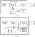
- FIG. 1 is a schematic diagram of a structure of a photovoltaic system according to an embodiment of this application.
- the photovoltaic system includes a plurality of photovoltaic modules, a direct current (DC) to direct current converter (a DC-DC converter), a direct current to alternating current (AC) converter (a DC-AC converter), an energy storage apparatus, and a control module.
- DC direct current
- AC direct current
- the photovoltaic system may be connected to a power grid, and transmit generated electric energy to the power grid.
- the photovoltaic system may be directly connected to a powered device, and directly supply generated electric energy to the powered device.
- the plurality of photovoltaic modules are connected to the DC-DC converter, and the plurality of photovoltaic modules are configured to: convert optical energy into a first direct current, and output the first direct current to the DC-DC converter.
- the energy storage apparatus is connected between the DC-DC converter and the DC-AC converter, and the DC-DC converter may convert the received first direct current into a second direct current.
- the energy storage apparatus can store excess electric energy when electric energy that is output by the DC-DC converter exceeds an electric energy demand of the power grid or a demand of the powered device, and output the stored electric energy to the power grid by using the DC-AC converter when the electric energy that is output by the DC-DC converter falls short of the electric energy demand.
- the DC-AC converter is connected to the power grid.
- the DC-AC converter may convert the received direct current into an alternating current and output the alternating current to the power grid.
- a transformer may further be connected between the photovoltaic system and the power grid, and the transformer boosts the alternating current provided by the photovoltaic system, to implement high-voltage transmission and the like. This should be known by a person skilled in the art, and is not limited in this application.
- the power grid usually supplies power to the control module.
- the photovoltaic system directly considers by default that a failure occurs at this time, and stops supplying power to a controller.
- the controller is configured to control the DC-DC converter, the DC-AC converter, and the energy storage apparatus. After the powered device or the power grid is troubleshot, power supply to the controller needs to be restored, so that the energy storage apparatus or the photovoltaic module in the photovoltaic system resupplies power to the power grid, thereby implementing a black start.
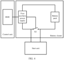
- UPS uninterruptible power supply
- the UPS is separately connected to the power grid and the controller, and is configured to: before the power grid is powered off, store electric energy transmitted on the power grid, and when the power grid is powered off, supply electric energy stored in the UPS to the controller.
- the controller After power supply to the controller is restored, the controller re-controls the DC-DC converter, the DC-AC converter, and the energy storage apparatus to normally work, and resupplies the generated electric energy to the power grid, to implement a black start.
- the UPS may further include a power supply module, and the UPS may restore power supply to the controller by using the power supply module.
- the new device UPS needs to be added to the photovoltaic system, and a volume and costs of the photovoltaic system are increased. Because the electric energy stored in the UPS is not highly frequently used, electric energy utilization of the entire photovoltaic system is further reduced. In addition, the power supply module needs to be additionally configured for the UPS, and this leads to high costs and a short lifetime.
- this application provides an energy storage apparatus, an energy storage apparatus control method, and a photovoltaic system, so that the photovoltaic system implements a black start by using a battery of the photovoltaic system without adding an additional power supply, thereby reducing costs of the photovoltaic system.
- FIG. 3 is a schematic diagram of a structure of an energy storage apparatus.
- the energy storage apparatus provided in this embodiment of this application includes a plurality of battery clusters, a plurality of conversion units, a start unit, and a controller.
- the energy storage apparatus is configured to supply power to a power grid.
- the power grid is configured to supply power to the controller.
- the energy storage apparatus includes the plurality of battery clusters, the plurality of conversion units, the start unit, and the controller.
- the controller includes a plurality of control units, the plurality of battery clusters are in a one-to-one correspondence with the plurality of control units and the plurality of conversion units, the plurality of battery clusters are in a one-to-one correspondence with the plurality of conversion units, and each battery cluster is connected to a corresponding conversion unit.
- Each battery cluster includes a battery pack and a control switch.
- Each conversion unit includes a direct current to direct current DC-DC converter, and each DC-DC converter is connected to a direct current bus.
- the start unit is configured to: after receiving a start signal, control the control switch in at least one of the plurality of battery clusters to close, to start a control unit corresponding to the at least one battery cluster corresponding to the control switch.
- Any one of the plurality of control units is configured to determine, based on a state of the control switch in the corresponding battery cluster, whether a black start mode is on, where the black start mode is a mode in which power supply to the power grid needs to be restored after the power grid is powered off or power supply to a system is restored by using the power grid; and when determining that the black start mode is on, control the DC-DC converter in the corresponding conversion unit to convert electric energy stored in the battery pack in the corresponding battery cluster into a target voltage for output and release, to energize the direct current bus.
- the energy storage apparatus may be fixed on a photovoltaic system.
- the energy storage apparatus may be flexible and detachable. That is, a fixed connection interface is provided on the photovoltaic system, and the energy storage apparatus may be connected to the photovoltaic system through the fixed connection interface.
- the battery pack in the battery cluster may be a single storage battery, or may be a storage battery cluster formed by a plurality of storage batteries.
- the storage battery may be a combination of one or more of a lead-carbon battery, a lithium iron phosphate battery, a ternary lithium battery, a sodium-sulfur battery, and a flow battery.
- the battery pack may be flexibly selected based on an actual application environment, a cost budget, and the like.
- the DC-DC converter included in the conversion unit is configured to: when electric energy generated by a photovoltaic module in the photovoltaic system exceeds an electric energy demand of the power grid, convert a received first direct current into a second direct current, and input the second direct current into the battery cluster in the energy storage apparatus, so that the battery cluster stores excess electric energy; and when the electric energy generated by the photovoltaic module falls short of an electric energy demand of a powered device, convert a second direct current generated by the battery cluster into a first direct current, and output the first direct current to the power grid.
- a transformer and a DC-AC converter may be further connected between the conversion unit and the power grid, the DC-AC converter may convert the received direct current into an alternating current and output the alternating current to the power grid, and the transformer boosts the alternating current provided by the photovoltaic system, to implement high-voltage transmission and the like.
- the DC-DC converter may release the electric energy stored in the battery pack in the corresponding battery cluster, so that the direct current bus is energized.
- the DC-DC converter may convert the electric energy stored in the battery pack in the corresponding battery cluster into the target voltage.
- the target voltage is less than a normal working voltage of the direct current bus.
- the controller may include a plurality of control units.
- the plurality of control units are also in a one-to-one correspondence with the plurality of conversion units.
- the control unit may be a general-purpose central processing unit (CPU), a general-purpose processor, digital signal processor (DSP), an application-specific integrated circuit (ASIC), a field programmable gate array (FPGA) or another programmable logic device, a transistor logic device, a hardware component, or any combination thereof.
- the control unit may implement or execute logical blocks, modules, and circuits in various examples described with reference to content disclosed in this application.
- the processor may be a combination of processors implementing a computing function, for example, a combination including one or more microprocessors, or a combination of a DSP and a microprocessor.
- each battery cluster further includes a first auxiliary power supply.
- a first electrode of the control switch is connected to one end of the first auxiliary power supply
- a second end of the battery pack is connected to the other end of the first auxiliary power supply
- the first electrode of the control switch is further connected to the start unit
- a second electrode of the control switch is separately connected to a first end of the battery pack and the start unit
- a control electrode of the control switch is connected to the first auxiliary power supply.
- the first auxiliary power supply in any one of the plurality of battery clusters is configured to: after the control switch in the battery cluster is closed, supply power to a battery management unit in the control unit corresponding to the battery cluster.
- Each control unit includes the battery management unit BMU.
- Any battery management unit in the plurality of control units is configured to: detect the state of the control switch in the battery cluster corresponding to the control unit; determine whether the black start mode is on; and when the control switch in the battery cluster corresponding to the control unit is closed, determine that the black start mode is on.
- the start signal is triggered, and the start unit controls the control switch in at least one of the battery clusters to close, to start the first auxiliary power supply.
- a conduction path is formed between the first auxiliary power supply and the battery management unit, so that the first auxiliary power supply supplies power to the battery management unit in the corresponding control unit.
- the battery management unit detects an electrical signal on the first auxiliary power supply. After determining that the detected electrical signal lasts for specified duration, the battery management unit controls the first auxiliary power supply to close the control switch. In this case, the battery management unit detects a closed state of the control switch again. When the control switch is closed, the battery management unit determines that the black start mode is on, that is, determines that the power grid is currently powered off, and power supply to the power grid needs to be restored.
- the first auxiliary power supply when the battery pack does not need to store or release the electric energy, the first auxiliary power supply may be further controlled by using the battery management unit, so that the first auxiliary power supply is enabled to control the control switch, to disconnect the battery pack from the first auxiliary power supply, thereby preventing the first auxiliary power supply from consuming the electric energy stored in the battery pack.
- control switch included in each battery cluster may further be a linked switch. Due to a structure of the linked switch, after a control switch is closed, a control switch in each of the other battery clusters may be driven to close together, to supply power to the first auxiliary power supply in each battery cluster, so that the photovoltaic system enters a black start mode as a whole.
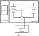
- FIG. 4 is a schematic diagram of a structure of a battery cluster according to an embodiment of this application.
- a plurality of batteries constitute a battery pack
- K1 is a control switch
- a BMU is a battery management unit.
- a connection relationship of devices in the battery cluster shown in FIG. 4 may be as follows: A first auxiliary power supply is connected to the battery management unit, a first end of the first auxiliary power supply is connected to a first electrode of K1, a second end of the first auxiliary power supply is connected to a second end of the battery pack, a second electrode of K1 is connected to a first end of the battery pack, and a control electrode of K1 is connected to a start unit.
- a conduction path is formed between the battery pack and the first auxiliary power supply by using the start unit.
- the battery pack transmits electric energy to the first auxiliary power supply, and the first auxiliary power supply generates an electrical signal.
- the battery management unit detects the electrical signal on the first auxiliary power supply, and after determining that the detected electrical signal lasts for specified duration, controls the first auxiliary power supply to close the control electrode of the control switch.
- the battery management unit detects a closed state of the control electrode again, and when K1 is closed, determines that a black start mode is on.
- the start unit is connected to a plurality of battery clusters, so that the start unit receives the start signal when the power grid is disconnected due to a failure, thereby forming the conduction path between the first auxiliary power supply in a battery module and the battery pack, to implement a black start.
- FIG. 5 is a schematic diagram of a structure of a start unit.
- the start unit includes a button switch, and the button switch is connected in parallel to any one or more of control switches in a plurality of battery clusters.
- a start signal received by the start unit may be a signal for which pressing duration is longer than specified duration and a pressure value of pressing is greater than a specified pressure value.
- the start unit may further include a plurality of button switches in a one-to-one correspondence with the plurality of battery clusters.
- Each button switch is connected in parallel to the control switch in the corresponding battery cluster.
- a plurality of second button switches may be adjacent or located at different locations.
- a first auxiliary power supply in each battery cluster may send a control signal to any control switch. Therefore, when any second button switch receives the start signal, the control switch in the corresponding battery cluster may be closed after receiving the control signal, and the control switch is closed after the first auxiliary power supply is energized.
- the switch in the start unit may be a contactor switch, a magnetic switch, or the like.
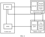
- each conversion unit further includes a second auxiliary power supply.
- the first auxiliary power supply in any one of the plurality of battery clusters is connected to the second auxiliary power supply in the conversion unit corresponding to the battery cluster.
- Each control unit includes a battery control unit (BCU).
- the first auxiliary power supply in any one of the plurality of battery clusters is further configured to start the second auxiliary power supply in the conversion unit corresponding to the battery cluster;
- the second auxiliary power supply in any one of the plurality of conversion units is configured to supply power to the battery control unit in the control unit corresponding to the battery cluster;
- any battery control unit in a plurality of control units is configured to: when determining that the black start mode is on, control a DC-DC converter in the conversion unit corresponding to the battery cluster to release electric energy stored in a battery pack in the corresponding battery cluster, to energize a direct current bus.
- FIG. 6 is a schematic diagram of a structure of an energy storage apparatus including a battery control unit.
- the first auxiliary power supply enables a second auxiliary power supply to start.
- the second auxiliary power supply is configured to supply power to the battery control unit in a corresponding control unit.
- the battery control unit determines whether a black start mode is on; and if the battery control unit is in the black start mode, controls a DC-DC converter in a corresponding conversion unit to release electric energy stored in a battery pack in a corresponding battery cluster, to energize a direct current bus.
- the battery control unit may communicate with a battery management unit, to determine whether the battery control unit already enters the black start mode.
- a battery control unit in each control unit communicates with the battery management unit in at least one of the following manners: a wired local area network (LAN), a serial bus (RS-485), a controller area network (controller area network, CAN) and a power line communication (PLC), a general packet radio service (GPRS), a wireless network, Bluetooth, ZigBee, and infrared.
- LAN local area network
- RS-485 serial bus
- controller area network controller area network
- PLC power line communication
- PLC power line communication
- GPRS general packet radio service
- wireless network Bluetooth, ZigBee, and infrared.
- the battery control unit may control connection and disconnection of a switching device in the DC-DC converter by using a control signal.
- the control signal may be a pulse width modulation (PWM) signal, and is used to adjust, to a target voltage by setting different duty cycles, a voltage that is output by the DC-DC converter.
- PWM pulse width modulation
- a specific manner of generating the control signal is not limited herein, and this should be known by a person skilled in the art.
- the switching device in the DC-DC converter may be one or more of a plurality of types of switching devices, such as a relay, a metal oxide semi-conductor field effect transistor, a bipolar junction transistor, an insulated gate bipolar transistor, and a gallium nitride power tube.
- the plurality of types of switching devices are not listed one by one in this embodiment of this application.
- Each switching device may include a first electrode, a second electrode, and a control electrode, where the control electrode is configured to control turn-on or turn-off of the switch. When the switch is turned on, a current may be transmitted between the first electrode and the second electrode of the switch. When the switch is turned off, a current cannot be transmitted between the first electrode and the second electrode of the switch.
- the metal oxide semi-conductor field effect transistor is used as an example.
- the control electrode of the switch is a gate, the first electrode of the switch may be a source of the switching device, and the second electrode may be a drain of the switching device. Alternatively, the first electrode may be a drain of the switch, and the second electrode may be a source of the switch.
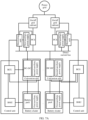
- FIG. 7A is a schematic diagram 1 of an entire structure of an energy storage apparatus.
- the energy storage apparatus further includes a plurality of power conversion systems PCSs.
- the plurality of power conversion systems are in a one-to-one correspondence with the plurality of conversion units. Any one of the plurality of conversion units is mutually connected to any one of the plurality of power conversion systems through the direct current bus.
- the energy storage apparatus further includes a plurality of on/off grid cabinets, a plurality of third auxiliary power supplies, and a plurality of system control unit SCUs.
- the plurality of power conversion systems are in a one-to-one correspondence with the plurality of on/off grid cabinets, the plurality of third auxiliary power supplies, and the plurality of system control unit SCUs.
- Any one of the plurality of third auxiliary power supplies is configured to obtain power from the direct current bus to start the monitoring unit corresponding to the power conversion system.
- Any battery control unit in the plurality of control units is further configured to: when determining that the black start mode is on, control the DC-DC converter in the conversion unit corresponding to the battery cluster to generate a disturbance signal at a specified frequency on the direct current bus.
- Any one of the plurality of system control unit is configured to: detect the disturbance signal on the direct current bus and a working state of the on/off grid cabinet corresponding to the power conversion system; and when the disturbance signal at the specified frequency is detected on the direct current bus and the on/off grid cabinet corresponding to the power conversion system is in a normal working state, start the power conversion system and the on/off grid cabinet corresponding to the power conversion system. After the power conversion system and the on/off grid cabinet are normally started, the entire energy storage apparatus is enabled to normally work, and supply power to a power grid, so that power supply to the power grid is restored.
- the monitoring unit may obtain a black start signal from the battery control unit, and after obtaining the black start signal, determine that the black start mode is on. When determining that the black start mode is on, the monitoring unit starts the power conversion system and the on/off grid cabinet.
- FIG. 7B is a schematic diagram 2 of an entire structure of an energy storage apparatus.
- any battery control unit in the plurality of control units is further configured to: when determining that a black start mode is on, control the DC-DC converter in the conversion unit corresponding to the battery cluster to generate a disturbance signal at a specified frequency on the direct current bus.
- the battery control unit controls the DC-DC converter to generate disturbance on the bus, and uses a specific bus voltage disturbance frequency to indicate that the black start mode is on, so that after receiving the bus voltage disturbance, all the system control unit decode the bus voltage disturbance, to determine that the black start mode is on.
- a form of the disturbance may be a rectangular wave, a sawtooth wave, a staircase wave, or the like, and the form of the disturbance is not limited herein.
- FIG. 7C is a schematic diagram 3 of an entire structure of an energy storage apparatus.
- the DC-DC converters are connected to power conversion systems, in a case that the battery control unit determines that a black start mode is on, the DC-DC converter in the corresponding conversion unit is controlled to generate a disturbance signal at a specified frequency on the direct current bus, and the specific bus voltage disturbance frequency is used to indicate that the black start mode is on.
- the monitoring unit connected to the DC-DC converter on one direct current bus decodes the bus voltage disturbance, to determine that the black start mode is on.
- on/off grid cabinets on the power grid are notified, by the on/off grid cabinet that is on the power grid and that corresponds to the monitoring unit, to enter the black start mode, and finally the other on/off grid cabinets perform downstream transmission separately, to enable the entire energy storage apparatus to complete a black start.
- An embodiment of this application provides an energy storage apparatus control method, applied to an energy storage apparatus.
- the energy storage apparatus includes: a plurality of battery clusters, a plurality of conversion units, a start unit, and a controller.
- the method includes: after receiving a start signal, controlling a control switch in at least one of the plurality of battery clusters to close, to start a control unit corresponding to the battery cluster; determining, based on a state of the control switch in the corresponding battery cluster, whether a black start mode is on, where the black start mode is a mode in which power supply to a power grid needs to be restored after the power grid is powered off; and when determining that the black start mode is on, controlling a DC-DC converter in the corresponding conversion unit to release electric energy stored in a battery pack in the corresponding battery cluster, to energize a direct current bus.
- the energy storage apparatus further includes a plurality of on/off grid cabinets, a plurality of third auxiliary power supplies, and a plurality of system control unit SCUs.
- a plurality of power conversion systems are in a one-to-one correspondence with the plurality of on/off grid cabinets, the plurality of third auxiliary power supplies, and the plurality of system control unit SCUs.
- the power conversion system includes the monitoring unit SCU.
- the method further includes: detecting a disturbance signal on the direct current bus and a working state of the on/off grid cabinet corresponding to the power conversion system; and when the disturbance signal at a specified frequency is detected on the direct current bus and the on/off grid cabinet corresponding to the power conversion system is in a normal working state, starting the power conversion system and the on/off grid cabinet corresponding to the power conversion system.
- the start signal when the start signal is triggered after the power grid connected to a photovoltaic system is powered off, the start signal is sent to the start unit. After receiving the start signal, the start unit controls the control switch in the at least one of the battery clusters to close, and starts the control unit corresponding to the control switch.
- the control unit may determine, based on the state of the control switch in the corresponding battery cluster, whether the black start mode is on; and when determining that the black start mode is on, control the DC-DC converter in the corresponding conversion unit to release the electric energy stored in the battery pack in the corresponding battery cluster, so that the direct current bus is energized, thereby implementing a black start without adding an additional device.
- the energy storage apparatus may alternatively use other structures.
- the other structures are not described one by one herein in this application.
- the foregoing energy storage apparatus and energy storage apparatus control method may also be applied to other fields in which a black start needs to be implemented, such as wind power generation, hydroelectric power generation, and thermal power generation.
- the black start may be implemented by using the foregoing apparatus and method, to reduce costs of the black start.
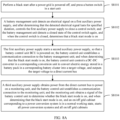
- the energy storage apparatus may be controlled by performing an energy storage apparatus control method shown in FIG. 8A , thereby implementing a black start.
- the control method mainly includes the following steps.
- S8101 Perform a black start after a power grid is powered off, and press a button switch in a start unit.
- a conduction path is formed between a first auxiliary power supply and a battery management unit, so that the first auxiliary power supply supplies power to the battery management unit in a corresponding control unit.
- the battery management unit detects an electrical signal on the first auxiliary power supply, and after determining that the detected electrical signal lasts for specified duration, controls the first auxiliary power supply to close a control switch.
- the battery management unit detects a closed state of the control switch again, and when the control switch is closed, determines that a black start mode is on.
- the first auxiliary power supply starts a second auxiliary power supply, so that a battery control unit BCU is powered on; the battery control unit establishes a communication connection to the battery management unit; and when determining that the black start mode is on, the battery control unit controls a DC-DC converter in a corresponding conversion unit to convert electric energy stored in a battery pack in a corresponding battery cluster into a target voltage, and outputs the target voltage to a direct current bus
- a third auxiliary power supply obtains power from the direct current bus to power on a monitoring unit, and the battery control unit establishes a communication connection to the monitoring unit; and the monitoring unit obtains a signal of the battery control unit to determine whether the black start mode is on, and when determining that the black start mode is on, and an on/off grid cabinet corresponding to a power conversion system is in a normal working state, starts all power conversion systems and all on/off grid cabinets.
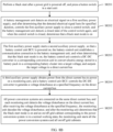
- the energy storage apparatus may be controlled by performing an energy storage apparatus control method shown in FIG. 8B , thereby implementing a black start.
- the control method mainly includes the following steps.
- step S8201 to step S8203 is the same as the method in S8101 to S8103 shown in FIG. 8A . Details are not described herein again.
- Step S8204 A third auxiliary power supply obtains power from the direct current bus to power on a monitoring unit, and the battery control unit BCU controls the DC-DC converter to generate voltage disturbance at a specified frequency on the direct current bus.
- Step S8205 All power conversion systems are connected on the same direct current bus, and each monitoring unit detects the voltage disturbance on the direct current bus; after receiving the voltage disturbance at the specified frequency, the monitoring unit decodes the voltage disturbance; and after the monitoring unit determines that the black start mode is on and an on/off grid cabinet corresponding to the power conversion system is in a normal working state, the monitoring unit starts all the power conversion systems and all on/off grid cabinets.
- the energy storage apparatus may be controlled by performing an energy storage apparatus control method shown in FIG. 8C , thereby implementing a black start.
- the control method mainly includes the following steps.
- step S8301 to step S8303 is the same as the method in S8101 to S8103 shown in FIG. 8A . Details are not described herein again.
- Step S8304 A third auxiliary power supply obtains power from the direct current bus to power on a monitoring unit, and the battery control unit BCU controls the DC-DC converter to generate voltage disturbance at a specified frequency on the direct current bus.
- Step S8305 All power conversion systems are connected to different direct current buses, and the power conversion system connected to the DC-DC converter detects the voltage disturbance on the bus; after receiving the voltage disturbance at the specified frequency, the monitoring unit decodes the voltage disturbance; after the monitoring unit determines that the black start mode is on and an on/off grid cabinet corresponding to the power conversion system is in a normal working state, the monitoring unit starts the power conversion system and the on/off grid cabinet corresponding to the power conversion system.
- Step S8306 The on/off grid cabinet notifies, through the bus on the power grid, another on/off grid cabinet to enter the black start mode.
- the photovoltaic system includes: a plurality of photovoltaic modules, a direct current to direct current DC-DC converter, and a direct current to alternating current DC-AC converter, a control module, and the energy storage apparatus defined in the foregoing embodiment.
- the plurality of photovoltaic modules are connected to the DC-DC converter, and are configured to: convert optical energy into a first direct current, and output the first direct current to the DC-DC converter.
- the DC-DC converter is separately connected to the DC-AC converter and the energy storage apparatus, and the DC-DC converter is configured to: convert the first direct current into a second direct current, and separately output the second direct current to the DC-AC converter and the energy storage apparatus.
- the energy storage apparatus is connected to the control module, and the energy storage apparatus is configured to supply power to the control module.
- the DC-AC converter is configured to: convert the second direct current into a first alternating current, and output the first alternating current.
- the control module is separately connected to the DC-DC converter and the DC-AC converter, and the control module is configured to control a working state of the DC-DC converter and a working state of the DC-AC converter. In a possible implementation, the control module is further configured to control a working state of the energy storage apparatus.
- this application may be provided as a method, a system, or a computer program product. Therefore, this application may use a form of a hardware-only embodiment, a software-only embodiment, or an embodiment with a combination of software and hardware. Moreover, this application may use a form of a computer program product that is implemented on one or more computer-usable storage media (including but not limited to a magnetic disk memory, a CD-ROM, an optical memory, and the like) that include computer-usable program code.
- a computer-usable storage media including but not limited to a magnetic disk memory, a CD-ROM, an optical memory, and the like
- These computer program instructions may be provided for a general-purpose computer, a dedicated computer, an embedded processor, or a processor of any other programmable data processing device to generate a machine, so that the instructions executed by a computer or a processor of any other programmable data processing device generate an apparatus for implementing a specific function in one or more processes in the flowcharts and/or in one or more blocks in the block diagrams.
- These computer program instructions may alternatively be stored in a computer-readable memory that can indicate a computer or another programmable data processing device to work in a specific manner, so that the instructions stored in the computer-readable memory generate an artifact that includes an instruction apparatus.
- the instruction apparatus implements a specific function in one or more processes in the flowcharts and/or in one or more blocks in the block diagrams.
Landscapes
- Engineering & Computer Science (AREA)
- Power Engineering (AREA)
- Business, Economics & Management (AREA)
- Emergency Management (AREA)
- Charge And Discharge Circuits For Batteries Or The Like (AREA)
- Supply And Distribution Of Alternating Current (AREA)
Claims (9)
- Appareil de stockage d'énergie, dans lequel l'appareil de stockage d'énergie est configuré pour alimenter en énergie un réseau électrique ; l'appareil de stockage d'énergie comprend :une pluralité de groupes de batteries, une pluralité d'unités de conversion, une unité de démarrage et un dispositif de commande ; le réseau électrique est configuré pour alimenter en énergie le dispositif de commande, le dispositif de commande comprend une pluralité d'unités de commande, la pluralité de groupes de batteries sont en correspondance biunivoque avec la pluralité d'unités de commande et la pluralité d'unités de conversion, et chaque groupe de batteries est connecté à une unité de conversion correspondante ; chaque groupe de batteries comprend un bloc-batterie et un commutateur de commande ; etchaque unité de conversion comprend un convertisseur de courant continu-courant continu, CC-CC, et chaque convertisseur CC-CC est connecté à un bus de courant continu ;l'unité de démarrage est configurée pour : après la réception d'un signal de démarrage, commander le commutateur de commande dans au moins l'un de la pluralité de groupes de batteries en position fermée, pour démarrer une unité de commande correspondant à l'au moins un groupe de batteries ; etl'une quelconque de la pluralité d'unités de commande est configurée pour : détecter, sur la base d'un état du commutateur de commande dans le groupe de batteries correspondant, si un mode de démarrage à froid est activé ; et lorsque le mode de démarrage à froid est activé, commander le convertisseur CC-CC dans l'unité de conversion correspondante pour libérer l'énergie électrique stockée dans le bloc-batterie dans le groupe de batteries correspondant, pour alimenter le bus de courant continu, dans lequel le mode de démarrage à froid est un mode dans lequel l'alimentation électrique du réseau électrique doit être rétablie après la mise hors tension du réseau électrique, dans lequel chaque unité de commande comprend une unité de gestion de batterie, BMU ;toute unité de gestion de batterie dans la pluralité d'unités de commande est configurée pour : détecter l'état du commutateur de commande dans le groupe de batteries correspondant à l'unité de commande ; déterminer si le mode de démarrage à froid est activé ; et lorsque le commutateur de commande dans le groupe de batteries correspondant à l'unité de commande est fermé, déterminer que le mode de démarrage à froid est activé ;caractérisé en ce quechaque groupe de batteries comprend également : une première alimentation électrique auxiliaire ; dans chaque groupe de batteries, une première électrode du commutateur de commande est connectée à une extrémité de la première alimentation électrique auxiliaire, une seconde extrémité du bloc-batterie est connectée à l'autre extrémité de la première alimentation électrique auxiliaire, la première électrode du commutateur de commande est également connectée à l'unité de démarrage, une seconde électrode du commutateur de commande est connectée séparément à une première extrémité du bloc-batterie et à l'unité de démarrage, et une électrode de commande du commutateur de commande est connectée à la première alimentation électrique auxiliaire ; etla première alimentation électrique auxiliaire dans l'un quelconque de la pluralité de groupes de batteries est configurée pour : après la fermeture du commutateur de commande dans le groupe de batteries, alimenter en énergie une unité de gestion de batterie dans l'unité de commande correspondant au groupe de batteries.
- Appareil de stockage d'énergie selon la revendication 1, dans lequel chaque unité de conversion comprend également une deuxième alimentation électrique auxiliaire ; la première alimentation électrique auxiliaire dans l'un quelconque de la pluralité de groupes de batteries est connectée à la deuxième alimentation électrique auxiliaire dans l'unité de conversion correspondant au groupe de batteries ; chaque unité de commande comprend une unité de commande de batterie, BCU ;la première alimentation électrique auxiliaire dans l'un quelconque de la pluralité de groupes de batteries est également configurée pour démarrer (S8103) la deuxième alimentation électrique auxiliaire dans l'unité de conversion correspondant au groupe de batteries ;la deuxième alimentation électrique auxiliaire dans l'une quelconque de la pluralité d'unités de conversion est configurée pour alimenter en énergie l'unité de commande de batterie dans l'unité de commande correspondant au groupe de batteries ; ettoute unité de commande de batterie dans la pluralité d'unités de commande est configurée pour : lors de la détermination que le mode de démarrage à froid est activé, commander le convertisseur CC-CC dans l'unité de conversion correspondant au groupe de batteries pour libérer l'énergie électrique stockée dans le bloc-batterie dans le groupe de batteries correspondant, pour alimenter le bus de courant continu.
- Appareil de stockage d'énergie selon la revendication 2, dans lequel l'unité de commande de batterie dans chaque unité de commande communique avec l'unité de gestion de batterie d'au moins l'une des manières suivantes : un réseau local, LAN, câblé, un bus série, un réseau de zone de contrôleur, CAN, et un courant porteur en ligne, PLC, un service général de radiocommunication par paquets GPRS, un réseau sans fil, Wi-Fi, Bluetooth, ZigBee ou infrarouge.
- Appareil de stockage d'énergie selon l'une quelconque des revendications 1 à 3, dans lequel l'appareil de stockage d'énergie comprend également une pluralité de systèmes de conversion de puissance, PCS, dans lequel la pluralité de systèmes de conversion de puissance sont en correspondance biunivoque avec la pluralité d'unités de conversion ; et
l'une quelconque de la pluralité d'unités de conversion est mutuellement connectée à l'un quelconque de la pluralité de systèmes de conversion de puissance à travers le bus de courant continu. - Appareil de stockage d'énergie selon la revendication 4, dans lequel l'appareil de stockage d'énergie comprend également une pluralité d'armoires sur/hors réseau, une pluralité de troisièmes alimentations électriques auxiliaires et une pluralité d'unités de commande de système, SCU ; et la pluralité de systèmes de conversion de puissance sont en correspondance biunivoque avec la pluralité d'armoires sur/hors réseau, la pluralité de troisièmes alimentations électriques auxiliaires et la pluralité d'unités de commande de système, SCU ;l'une quelconque de la pluralité de troisièmes alimentations électriques auxiliaires est configurée pour obtenir (S8104) une puissance à partir du bus de courant continu pour démarrer l'unité de surveillance correspondant au système de conversion de puissance ;toute unité de commande de batterie dans la pluralité d'unités de commande est également configurée pour : lorsqu'il est déterminé que le mode de démarrage à froid est activé, commander le convertisseur CC-CC dans l'unité de conversion correspondant au groupe de batteries pour générer un signal de perturbation à une fréquence spécifiée sur le bus de courant continu ; etl'une quelconque de la pluralité d'unités de commande de système est configurée pour : détecter le signal de perturbation (S8205) sur le bus de courant continu et un état de fonctionnement de l'armoire sur/hors réseau correspondant au système de conversion de puissance, etlorsque le signal de perturbation à la fréquence spécifiée est détecté sur le bus de courant continu et que l'armoire sur/hors réseau correspondant au système de conversion de puissance est dans un état de fonctionnement normal, démarrer le système de conversion de puissance et l'armoire sur/hors réseau correspondant au système de conversion de puissance.
- Appareil de stockage d'énergie selon l'une quelconque des revendications 1 à 5, dans lequel l'unité de démarrage comprend un commutateur à bouton, dans lequel le commutateur à bouton est connecté en parallèle à un ou plusieurs parmi des commutateurs de commande dans la pluralité de groupes de batteries.
- Système photovoltaïque, dans lequel le système photovoltaïque comprend une pluralité de modules photovoltaïques, un convertisseur de courant continu- courant continu, CC-CC, un convertisseur de courant continu-courant alternatif, CC-CA, un module de commande et l'appareil de stockage d'énergie selon l'une quelconque des revendications 1 à 6, dans lequella pluralité de modules photovoltaïques sont connectés au convertisseur CC-CC, et la pluralité de modules photovoltaïques sont configurés pour : convertir l'énergie optique en un premier courant continu, et délivrer le premier courant continu au convertisseur CC-CC ;le convertisseur CC-CC est connecté séparément au convertisseur CC-CA et à l'appareil de stockage d'énergie, et le convertisseur CC-CC est configuré pour : convertir le premier courant continu en un second courant continu, et délivrer séparément le second courant continu au convertisseur CC-CA et à l'appareil de stockage d'énergie ;l'appareil de stockage d'énergie est connecté au module de commande, et l'appareil de stockage d'énergie est configuré pour alimenter en énergie le module de commande ;le convertisseur CC-CA est configuré pour : convertir le second courant continu en un courant alternatif et délivrer le courant alternatif ; etle module de commande est connecté séparément au convertisseur CC-CC et au convertisseur CC-CA, et le module de commande est configuré pour commander un état de fonctionnement du convertisseur CC-CC et un état de fonctionnement du convertisseur CC-CA.
- Système selon la revendication 7, dans lequel le module de commande est également configuré pour commander un état de fonctionnement de l'appareil de stockage d'énergie.
- Procédé de commande d'appareil de stockage d'énergie, appliqué à un appareil de stockage d'énergie, dans lequel l'appareil de stockage d'énergie comprend une pluralité de groupes de batteries, une pluralité d'unités de conversion, une unité de démarrage et un dispositif de commande ; et le procédé comprend :après la réception d'un signal de démarrage, la commande d'un commutateur de commande dans au moins l'un de la pluralité de groupes de batteries en position fermée, pour démarrer une unité de commande correspondant au groupe de batteries ;le fait de détecter, sur la base d'un état du commutateur de commande dans le groupe de batteries correspondant, si un mode de démarrage à froid est activé, dans lequel le mode de démarrage à froid est un mode dans lequel l'alimentation électrique d'un réseau électrique doit être rétablie après la mise hors tension du réseau électrique ; etlorsque le mode de démarrage à froid est activé, la commande d'un convertisseur CC-CC dans l'unité de conversion correspondante pour libérer l'énergie électrique stockée dans un bloc-batterie dans le groupe de batteries correspondant, pour alimenter un bus de courant continu,caractérisé en ce quel'appareil de stockage d'énergie comprend également une pluralité d'armoires sur/hors réseau, une pluralité de troisièmes alimentations électriques auxiliaires et une pluralité d'unités de commande de système, SCU ; et la pluralité de systèmes de conversion de puissance sont en correspondance biunivoque avec la pluralité d'armoires sur/hors réseau, la pluralité de troisièmes alimentations électriques auxiliaires et la pluralité d'unités de commande de système, SCU ; etle procédé comprend également :la détection d'un signal de perturbation sur le bus de courant continu et d'un état de fonctionnement de l'armoire sur/hors réseau correspondant au système de conversion de puissance ; etlorsque le signal de perturbation à une fréquence spécifiée est détecté sur le bus de courant continu et que l'armoire sur/hors réseau correspondant au système de conversion de puissance est dans un état de fonctionnement normal, le démarrage du système de conversion de puissance et de l'armoire sur/hors réseau correspondant au système de conversion de puissance.
Applications Claiming Priority (2)
| Application Number | Priority Date | Filing Date | Title |
|---|---|---|---|
| CN202110732769.2A CN113629757B (zh) | 2021-06-30 | 2021-06-30 | 一种储能装置、储能装置控制方法以及光伏系统 |
| PCT/CN2022/101667 WO2023274179A1 (fr) | 2021-06-30 | 2022-06-27 | Appareil de stockage d'énergie, procédé de commande pour appareil de stockage d'énergie et système photovoltaïque |
Publications (3)
| Publication Number | Publication Date |
|---|---|
| EP4199295A1 EP4199295A1 (fr) | 2023-06-21 |
| EP4199295A4 EP4199295A4 (fr) | 2024-07-24 |
| EP4199295B1 true EP4199295B1 (fr) | 2025-05-21 |
Family
ID=78378629
Family Applications (1)
| Application Number | Title | Priority Date | Filing Date |
|---|---|---|---|
| EP22831993.5A Active EP4199295B1 (fr) | 2021-06-30 | 2022-06-27 | Appareil de stockage d'énergie, procédé de commande pour appareil de stockage d'énergie et système photovoltaïque |
Country Status (5)
| Country | Link |
|---|---|
| US (1) | US12368317B2 (fr) |
| EP (1) | EP4199295B1 (fr) |
| CN (1) | CN113629757B (fr) |
| ES (1) | ES3035845T3 (fr) |
| WO (1) | WO2023274179A1 (fr) |
Families Citing this family (20)
| Publication number | Priority date | Publication date | Assignee | Title |
|---|---|---|---|---|
| CN113629757B (zh) | 2021-06-30 | 2024-02-09 | 华为数字能源技术有限公司 | 一种储能装置、储能装置控制方法以及光伏系统 |
| CN116388316A (zh) * | 2021-12-30 | 2023-07-04 | 奥动新能源汽车科技有限公司 | 电池管理设备、充电装置 |
| CN114336708B (zh) * | 2021-12-31 | 2025-09-30 | 杭州协能科技股份有限公司 | 储能系统的黑启动方法及储能系统 |
| CN114567004B (zh) * | 2022-02-24 | 2024-04-02 | 江苏阿诗特能源科技股份有限公司 | 一种基于光伏储能系统的黑启动控制系统和方法 |
| CN114665172B (zh) * | 2022-04-20 | 2025-09-02 | 阳光电源股份有限公司 | 一种储能电池柜及其安防自启动方法 |
| CN114825454B (zh) * | 2022-06-30 | 2022-11-04 | 西安热工研究院有限公司 | 一种风光储火联合运行的黑启动系统及方法 |
| US12512522B2 (en) * | 2022-08-23 | 2025-12-30 | GE Grid GmbH | Systems and methods for self-derived auxiliary power for energy storage systems |
| CN115622196A (zh) * | 2022-11-10 | 2023-01-17 | 阳光电源股份有限公司 | 一种储能变流器、储能系统及供电方法 |
| CN115733237B (zh) * | 2022-11-23 | 2025-11-18 | 华为数字能源技术有限公司 | 储能系统和黑启动装置 |
| CN115622207B (zh) * | 2022-12-20 | 2023-03-28 | 广东采日能源科技有限公司 | 储能系统及其控制方法 |
| CN115940295B (zh) * | 2023-02-21 | 2023-06-13 | 国网山东省电力公司乳山市供电公司 | 电能监测控制系统及方法 |
| CN116316761A (zh) * | 2023-03-21 | 2023-06-23 | 华为数字能源技术有限公司 | 一种储能柜和储能系统 |
| CN116054422B (zh) * | 2023-04-03 | 2023-08-11 | 宁德时代新能源科技股份有限公司 | 储能装置和储能系统 |
| CN116317180B (zh) * | 2023-05-22 | 2023-09-22 | 宁德时代新能源科技股份有限公司 | 储能装置及其控制方法 |
| CN117200416A (zh) * | 2023-07-31 | 2023-12-08 | 华为数字能源技术有限公司 | 一种电池包、储能系统及供电方法 |
| CN117375054B (zh) * | 2023-12-07 | 2024-02-27 | 上海派能能源科技股份有限公司 | 储能系统高压接入控制方法、储能系统、设备及存储介质 |
| CN118630801A (zh) * | 2024-03-27 | 2024-09-10 | 华为数字能源技术有限公司 | 供电系统 |
| CN121889927A (zh) * | 2024-04-08 | 2026-04-17 | 宁德时代新能源科技股份有限公司 | 控制箱、储能装置以及用电系统 |
| CN118473061B (zh) * | 2024-07-11 | 2024-10-25 | 杭州协能科技股份有限公司 | 一种储能系统的黑启动控制方法 |
| CN120185031B (zh) * | 2025-02-19 | 2025-10-31 | 宁德时代新能源科技股份有限公司 | 黑启动控制的方法、储能装置和储能系统 |
Family Cites Families (14)
| Publication number | Priority date | Publication date | Assignee | Title |
|---|---|---|---|---|
| EP3202007A1 (fr) * | 2014-10-02 | 2017-08-09 | First Solar, Inc | Système pour le fonctionnement d'une centrale électrique photovoltaïque et collecte intérieure de courant continu |
| JP6689093B2 (ja) * | 2015-02-17 | 2020-04-28 | 株式会社 シリコンプラス | 系統連系パワーコンディショナー及び分散型電力供給ネットワーク |
| CN204668965U (zh) * | 2015-05-04 | 2015-09-23 | 华电电力科学研究院 | 一种基于光伏和储能的分布式微网黑启动控制系统 |
| CN105515046B (zh) | 2015-12-29 | 2019-06-04 | 深圳市科陆电子科技股份有限公司 | 黑启动装置 |
| CN106788140B (zh) * | 2017-01-20 | 2018-08-28 | 合肥聚能新能源科技有限公司 | 一种模块化共直流母线光伏储能系统 |
| CN106712092B (zh) * | 2017-01-25 | 2018-11-23 | 上海电气分布式能源科技有限公司 | 具有黑启动功能的系统及其黑启动方法 |
| US10935945B2 (en) * | 2017-07-19 | 2021-03-02 | Arizona Public Service Company | Methods and apparatus for power generation and distribution |
| EP3471231A1 (fr) * | 2017-10-13 | 2019-04-17 | Ørsted Wind Power A/S | Procédé de démarrage à froid d'un réseau électrique |
| DE102018130453A1 (de) * | 2018-11-30 | 2020-06-04 | Sma Solar Technology Ag | Verfahren zur elektrischen Versorgung eines Wechselrichters, Anlagenkomponente, Wechselrichter und Energieerzeugungsanlage mit einer derartigen Anlagenkomponente |
| CN111478306B (zh) * | 2020-05-14 | 2021-07-02 | 山西大学 | 一种抑制含复合储能直流微电网母线电压波动的策略 |
| CN112636435A (zh) * | 2020-11-23 | 2021-04-09 | 阳光电源股份有限公司 | 一种储能系统 |
| CN112787344B (zh) * | 2021-01-27 | 2024-11-08 | 广州智光储能科技有限公司 | 并联储能变流器离网转并网的控制方法及装置 |
| CN112952912B (zh) * | 2021-03-23 | 2023-01-13 | 华为数字能源技术有限公司 | 储能系统及其黑启动方法 |
| CN113629757B (zh) * | 2021-06-30 | 2024-02-09 | 华为数字能源技术有限公司 | 一种储能装置、储能装置控制方法以及光伏系统 |
-
2021
- 2021-06-30 CN CN202110732769.2A patent/CN113629757B/zh active Active
-
2022
- 2022-06-27 EP EP22831993.5A patent/EP4199295B1/fr active Active
- 2022-06-27 ES ES22831993T patent/ES3035845T3/es active Active
- 2022-06-27 WO PCT/CN2022/101667 patent/WO2023274179A1/fr not_active Ceased
-
2023
- 2023-12-30 US US18/401,455 patent/US12368317B2/en active Active
Also Published As
| Publication number | Publication date |
|---|---|
| CN113629757B (zh) | 2024-02-09 |
| WO2023274179A1 (fr) | 2023-01-05 |
| EP4199295A1 (fr) | 2023-06-21 |
| US20240136850A1 (en) | 2024-04-25 |
| CN113629757A (zh) | 2021-11-09 |
| US12368317B2 (en) | 2025-07-22 |
| ES3035845T3 (en) | 2025-09-10 |
| US20240235252A9 (en) | 2024-07-11 |
| EP4199295A4 (fr) | 2024-07-24 |
Similar Documents
| Publication | Publication Date | Title |
|---|---|---|
| US12368317B2 (en) | Energy storage apparatus, energy storage apparatus control method, and photovoltaic system | |
| US20240332980A1 (en) | Photovoltaic energy storage system and photovoltaic energy storage scheduling method | |
| CN100588077C (zh) | 一种太阳能与市电互补式不间断供电系统 | |
| CN102214945B (zh) | 一种基于蓄电池并联的直流电源系统 | |
| WO2022166364A1 (fr) | Système de distribution de puissance, procédé de commande pour système de distribution de puissance et véhicule à énergie nouvelle | |
| CN104065154A (zh) | 一种变频器应急供电系统 | |
| US12494648B2 (en) | Control method of energy storage apparatus, energy storage apparatus, and photovoltaic power generation system | |
| EP4518076A1 (fr) | Armoire de stockage d'énergie et système de stockage d'énergie | |
| CN112952912B (zh) | 储能系统及其黑启动方法 | |
| CN114696389B (zh) | 一种储能系统 | |
| EP4152550A1 (fr) | Appareil d'alimentation sans coupure sans partage de courant, procédé de dérivation et système de connexion parallèle d'alimentation sans coupure | |
| JP5450685B2 (ja) | 電力変換装置 | |
| JP6210952B2 (ja) | 電力供給システム | |
| CN220822697U (zh) | 供电电路、电源和不间断电源 | |
| CN116365653B (zh) | 供电电路、功率转换设备及储能设备 | |
| CN214255824U (zh) | 不间断供电电路及储能系统 | |
| CN112865669A (zh) | 基于光伏发电、电池储能与电网的直流供电方法及系统 | |
| EP4395095B1 (fr) | Alimentation sans coupure et procédé de commutation d'alimentation | |
| CN221767648U (zh) | 一种在离网状态下具有自供电能力的配电系统和供电系统 | |
| KR20200113870A (ko) | Lvdc 저압배전 시스템에 적용되는 dc/dc 컨버터 | |
| KR101255470B1 (ko) | 에너지 저장 시스템 | |
| CN122051982A (zh) | 一种用于显示屏的多源供电方法、系统及设备 |
Legal Events
| Date | Code | Title | Description |
|---|---|---|---|
| STAA | Information on the status of an ep patent application or granted ep patent |
Free format text: STATUS: THE INTERNATIONAL PUBLICATION HAS BEEN MADE |
|
| PUAI | Public reference made under article 153(3) epc to a published international application that has entered the european phase |
Free format text: ORIGINAL CODE: 0009012 |
|
| STAA | Information on the status of an ep patent application or granted ep patent |
Free format text: STATUS: REQUEST FOR EXAMINATION WAS MADE |
|
| 17P | Request for examination filed |
Effective date: 20230315 |
|
| AK | Designated contracting states |
Kind code of ref document: A1 Designated state(s): AL AT BE BG CH CY CZ DE DK EE ES FI FR GB GR HR HU IE IS IT LI LT LU LV MC MK MT NL NO PL PT RO RS SE SI SK SM TR |
|
| A4 | Supplementary search report drawn up and despatched |
Effective date: 20240625 |
|
| RIC1 | Information provided on ipc code assigned before grant |
Ipc: H02J 7/35 20060101ALI20240619BHEP Ipc: H02J 3/32 20060101ALI20240619BHEP Ipc: H02J 3/38 20060101AFI20240619BHEP |
|
| DAV | Request for validation of the european patent (deleted) | ||
| DAX | Request for extension of the european patent (deleted) | ||
| GRAP | Despatch of communication of intention to grant a patent |
Free format text: ORIGINAL CODE: EPIDOSNIGR1 |
|
| STAA | Information on the status of an ep patent application or granted ep patent |
Free format text: STATUS: GRANT OF PATENT IS INTENDED |
|
| INTG | Intention to grant announced |
Effective date: 20250117 |
|
| GRAS | Grant fee paid |
Free format text: ORIGINAL CODE: EPIDOSNIGR3 |
|
| GRAA | (expected) grant |
Free format text: ORIGINAL CODE: 0009210 |
|
| STAA | Information on the status of an ep patent application or granted ep patent |
Free format text: STATUS: THE PATENT HAS BEEN GRANTED |
|
| AK | Designated contracting states |
Kind code of ref document: B1 Designated state(s): AL AT BE BG CH CY CZ DE DK EE ES FI FR GB GR HR HU IE IS IT LI LT LU LV MC MK MT NL NO PL PT RO RS SE SI SK SM TR |
|
| REG | Reference to a national code |
Ref country code: GB Ref legal event code: FG4D |
|
| REG | Reference to a national code |
Ref country code: CH Ref legal event code: EP |
|
| P01 | Opt-out of the competence of the unified patent court (upc) registered |
Free format text: CASE NUMBER: APP_20288/2025 Effective date: 20250429 |
|
| REG | Reference to a national code |
Ref country code: DE Ref legal event code: R096 Ref document number: 602022015055 Country of ref document: DE |
|
| REG | Reference to a national code |
Ref country code: IE Ref legal event code: FG4D |
|
| PGFP | Annual fee paid to national office [announced via postgrant information from national office to epo] |
Ref country code: DE Payment date: 20250507 Year of fee payment: 4 |
|
| PGFP | Annual fee paid to national office [announced via postgrant information from national office to epo] |
Ref country code: NL Payment date: 20250616 Year of fee payment: 4 |
|
| PGFP | Annual fee paid to national office [announced via postgrant information from national office to epo] |
Ref country code: AT Payment date: 20250721 Year of fee payment: 4 |
|
| REG | Reference to a national code |
Ref country code: NL Ref legal event code: FP |
|
| REG | Reference to a national code |
Ref country code: ES Ref legal event code: FG2A Ref document number: 3035845 Country of ref document: ES Kind code of ref document: T3 Effective date: 20250910 |
|
| PG25 | Lapsed in a contracting state [announced via postgrant information from national office to epo] |
Ref country code: FI Free format text: LAPSE BECAUSE OF FAILURE TO SUBMIT A TRANSLATION OF THE DESCRIPTION OR TO PAY THE FEE WITHIN THE PRESCRIBED TIME-LIMIT Effective date: 20250521 Ref country code: PT Free format text: LAPSE BECAUSE OF FAILURE TO SUBMIT A TRANSLATION OF THE DESCRIPTION OR TO PAY THE FEE WITHIN THE PRESCRIBED TIME-LIMIT Effective date: 20250922 |
|
| PGFP | Annual fee paid to national office [announced via postgrant information from national office to epo] |
Ref country code: ES Payment date: 20250703 Year of fee payment: 4 |
|
| REG | Reference to a national code |
Ref country code: LT Ref legal event code: MG9D |
|
| PG25 | Lapsed in a contracting state [announced via postgrant information from national office to epo] |
Ref country code: NO Free format text: LAPSE BECAUSE OF FAILURE TO SUBMIT A TRANSLATION OF THE DESCRIPTION OR TO PAY THE FEE WITHIN THE PRESCRIBED TIME-LIMIT Effective date: 20250821 Ref country code: GR Free format text: LAPSE BECAUSE OF FAILURE TO SUBMIT A TRANSLATION OF THE DESCRIPTION OR TO PAY THE FEE WITHIN THE PRESCRIBED TIME-LIMIT Effective date: 20250822 |
|
| PG25 | Lapsed in a contracting state [announced via postgrant information from national office to epo] |
Ref country code: PL Free format text: LAPSE BECAUSE OF FAILURE TO SUBMIT A TRANSLATION OF THE DESCRIPTION OR TO PAY THE FEE WITHIN THE PRESCRIBED TIME-LIMIT Effective date: 20250521 |
|
| PG25 | Lapsed in a contracting state [announced via postgrant information from national office to epo] |
Ref country code: BG Free format text: LAPSE BECAUSE OF FAILURE TO SUBMIT A TRANSLATION OF THE DESCRIPTION OR TO PAY THE FEE WITHIN THE PRESCRIBED TIME-LIMIT Effective date: 20250521 |
|
| PG25 | Lapsed in a contracting state [announced via postgrant information from national office to epo] |
Ref country code: HR Free format text: LAPSE BECAUSE OF FAILURE TO SUBMIT A TRANSLATION OF THE DESCRIPTION OR TO PAY THE FEE WITHIN THE PRESCRIBED TIME-LIMIT Effective date: 20250521 |
|
| PG25 | Lapsed in a contracting state [announced via postgrant information from national office to epo] |
Ref country code: RS Free format text: LAPSE BECAUSE OF FAILURE TO SUBMIT A TRANSLATION OF THE DESCRIPTION OR TO PAY THE FEE WITHIN THE PRESCRIBED TIME-LIMIT Effective date: 20250821 |
|
| PG25 | Lapsed in a contracting state [announced via postgrant information from national office to epo] |
Ref country code: IS Free format text: LAPSE BECAUSE OF FAILURE TO SUBMIT A TRANSLATION OF THE DESCRIPTION OR TO PAY THE FEE WITHIN THE PRESCRIBED TIME-LIMIT Effective date: 20250921 |
|
| PG25 | Lapsed in a contracting state [announced via postgrant information from national office to epo] |
Ref country code: LV Free format text: LAPSE BECAUSE OF FAILURE TO SUBMIT A TRANSLATION OF THE DESCRIPTION OR TO PAY THE FEE WITHIN THE PRESCRIBED TIME-LIMIT Effective date: 20250521 |
|
| REG | Reference to a national code |
Ref country code: AT Ref legal event code: MK05 Ref document number: 1797648 Country of ref document: AT Kind code of ref document: T Effective date: 20250521 |
|
| PG25 | Lapsed in a contracting state [announced via postgrant information from national office to epo] |
Ref country code: AT Free format text: LAPSE BECAUSE OF FAILURE TO SUBMIT A TRANSLATION OF THE DESCRIPTION OR TO PAY THE FEE WITHIN THE PRESCRIBED TIME-LIMIT Effective date: 20250521 Ref country code: DK Free format text: LAPSE BECAUSE OF FAILURE TO SUBMIT A TRANSLATION OF THE DESCRIPTION OR TO PAY THE FEE WITHIN THE PRESCRIBED TIME-LIMIT Effective date: 20250521 Ref country code: SM Free format text: LAPSE BECAUSE OF FAILURE TO SUBMIT A TRANSLATION OF THE DESCRIPTION OR TO PAY THE FEE WITHIN THE PRESCRIBED TIME-LIMIT Effective date: 20250521 |
|
| PG25 | Lapsed in a contracting state [announced via postgrant information from national office to epo] |
Ref country code: CZ Free format text: LAPSE BECAUSE OF FAILURE TO SUBMIT A TRANSLATION OF THE DESCRIPTION OR TO PAY THE FEE WITHIN THE PRESCRIBED TIME-LIMIT Effective date: 20250521 |
|
| PG25 | Lapsed in a contracting state [announced via postgrant information from national office to epo] |
Ref country code: EE Free format text: LAPSE BECAUSE OF FAILURE TO SUBMIT A TRANSLATION OF THE DESCRIPTION OR TO PAY THE FEE WITHIN THE PRESCRIBED TIME-LIMIT Effective date: 20250521 |
|
| PG25 | Lapsed in a contracting state [announced via postgrant information from national office to epo] |
Ref country code: SK Free format text: LAPSE BECAUSE OF FAILURE TO SUBMIT A TRANSLATION OF THE DESCRIPTION OR TO PAY THE FEE WITHIN THE PRESCRIBED TIME-LIMIT Effective date: 20250521 |
|
| REG | Reference to a national code |
Ref country code: CH Ref legal event code: H13 Free format text: ST27 STATUS EVENT CODE: U-0-0-H10-H13 (AS PROVIDED BY THE NATIONAL OFFICE) Effective date: 20260127 |
|
| PG25 | Lapsed in a contracting state [announced via postgrant information from national office to epo] |
Ref country code: IT Free format text: LAPSE BECAUSE OF FAILURE TO SUBMIT A TRANSLATION OF THE DESCRIPTION OR TO PAY THE FEE WITHIN THE PRESCRIBED TIME-LIMIT Effective date: 20250521 |
|
| PG25 | Lapsed in a contracting state [announced via postgrant information from national office to epo] |
Ref country code: LU Free format text: LAPSE BECAUSE OF NON-PAYMENT OF DUE FEES Effective date: 20250627 |
|
| PG25 | Lapsed in a contracting state [announced via postgrant information from national office to epo] |
Ref country code: MC Free format text: LAPSE BECAUSE OF FAILURE TO SUBMIT A TRANSLATION OF THE DESCRIPTION OR TO PAY THE FEE WITHIN THE PRESCRIBED TIME-LIMIT Effective date: 20250521 |
|
| REG | Reference to a national code |
Ref country code: DE Ref legal event code: R097 Ref document number: 602022015055 Country of ref document: DE |
|
| REG | Reference to a national code |
Ref country code: BE Ref legal event code: MM Effective date: 20250630 |
|
| PG25 | Lapsed in a contracting state [announced via postgrant information from national office to epo] |
Ref country code: RO Free format text: LAPSE BECAUSE OF FAILURE TO SUBMIT A TRANSLATION OF THE DESCRIPTION OR TO PAY THE FEE WITHIN THE PRESCRIBED TIME-LIMIT Effective date: 20250521 |
|
| PLBE | No opposition filed within time limit |
Free format text: ORIGINAL CODE: 0009261 |
|
| STAA | Information on the status of an ep patent application or granted ep patent |
Free format text: STATUS: NO OPPOSITION FILED WITHIN TIME LIMIT |
|
| REG | Reference to a national code |
Ref country code: CH Ref legal event code: L10 Free format text: ST27 STATUS EVENT CODE: U-0-0-L10-L00 (AS PROVIDED BY THE NATIONAL OFFICE) Effective date: 20260402 |
|
| PG25 | Lapsed in a contracting state [announced via postgrant information from national office to epo] |
Ref country code: IE Free format text: LAPSE BECAUSE OF NON-PAYMENT OF DUE FEES Effective date: 20250627 |
|
| PG25 | Lapsed in a contracting state [announced via postgrant information from national office to epo] |
Ref country code: BE Free format text: LAPSE BECAUSE OF NON-PAYMENT OF DUE FEES Effective date: 20250630 |
|
| PG25 | Lapsed in a contracting state [announced via postgrant information from national office to epo] |
Ref country code: FR Free format text: LAPSE BECAUSE OF NON-PAYMENT OF DUE FEES Effective date: 20250721 |
|
| PG25 | Lapsed in a contracting state [announced via postgrant information from national office to epo] |
Ref country code: CH Free format text: LAPSE BECAUSE OF NON-PAYMENT OF DUE FEES Effective date: 20250630 |
|
| 26N | No opposition filed |
Effective date: 20260224 |