EP4199298A1 - Appareil de charge et de décharge et son procédé de transmission de puissance - Google Patents
Appareil de charge et de décharge et son procédé de transmission de puissance Download PDFInfo
- Publication number
- EP4199298A1 EP4199298A1 EP21902295.1A EP21902295A EP4199298A1 EP 4199298 A1 EP4199298 A1 EP 4199298A1 EP 21902295 A EP21902295 A EP 21902295A EP 4199298 A1 EP4199298 A1 EP 4199298A1
- Authority
- EP
- European Patent Office
- Prior art keywords
- alternating current
- battery
- mode
- energy transmission
- transmission mode
- Prior art date
- Legal status (The legal status is an assumption and is not a legal conclusion. Google has not performed a legal analysis and makes no representation as to the accuracy of the status listed.)
- Granted
Links
Images
Classifications
-
- B—PERFORMING OPERATIONS; TRANSPORTING
- B60—VEHICLES IN GENERAL
- B60L—PROPULSION OF ELECTRICALLY-PROPELLED VEHICLES; SUPPLYING ELECTRIC POWER FOR AUXILIARY EQUIPMENT OF ELECTRICALLY-PROPELLED VEHICLES; ELECTRODYNAMIC BRAKE SYSTEMS FOR VEHICLES IN GENERAL; MAGNETIC SUSPENSION OR LEVITATION FOR VEHICLES; MONITORING OPERATING VARIABLES OF ELECTRICALLY-PROPELLED VEHICLES; ELECTRIC SAFETY DEVICES FOR ELECTRICALLY-PROPELLED VEHICLES
- B60L1/00—Supplying electric power to auxiliary equipment of vehicles
- B60L1/006—Supplying electric power to auxiliary equipment of vehicles to power outlets
-
- B—PERFORMING OPERATIONS; TRANSPORTING
- B60—VEHICLES IN GENERAL
- B60L—PROPULSION OF ELECTRICALLY-PROPELLED VEHICLES; SUPPLYING ELECTRIC POWER FOR AUXILIARY EQUIPMENT OF ELECTRICALLY-PROPELLED VEHICLES; ELECTRODYNAMIC BRAKE SYSTEMS FOR VEHICLES IN GENERAL; MAGNETIC SUSPENSION OR LEVITATION FOR VEHICLES; MONITORING OPERATING VARIABLES OF ELECTRICALLY-PROPELLED VEHICLES; ELECTRIC SAFETY DEVICES FOR ELECTRICALLY-PROPELLED VEHICLES
- B60L53/00—Methods of charging batteries, specially adapted for electric vehicles; Charging stations or on-board charging equipment therefor; Exchange of energy storage elements in electric vehicles
- B60L53/20—Methods of charging batteries, specially adapted for electric vehicles; Charging stations or on-board charging equipment therefor; Exchange of energy storage elements in electric vehicles characterised by converters located in the vehicle
-
- B—PERFORMING OPERATIONS; TRANSPORTING
- B60—VEHICLES IN GENERAL
- B60L—PROPULSION OF ELECTRICALLY-PROPELLED VEHICLES; SUPPLYING ELECTRIC POWER FOR AUXILIARY EQUIPMENT OF ELECTRICALLY-PROPELLED VEHICLES; ELECTRODYNAMIC BRAKE SYSTEMS FOR VEHICLES IN GENERAL; MAGNETIC SUSPENSION OR LEVITATION FOR VEHICLES; MONITORING OPERATING VARIABLES OF ELECTRICALLY-PROPELLED VEHICLES; ELECTRIC SAFETY DEVICES FOR ELECTRICALLY-PROPELLED VEHICLES
- B60L55/00—Arrangements for supplying energy stored within a vehicle to a power network, i.e. vehicle-to-grid [V2G] arrangements
-
- B—PERFORMING OPERATIONS; TRANSPORTING
- B60—VEHICLES IN GENERAL
- B60L—PROPULSION OF ELECTRICALLY-PROPELLED VEHICLES; SUPPLYING ELECTRIC POWER FOR AUXILIARY EQUIPMENT OF ELECTRICALLY-PROPELLED VEHICLES; ELECTRODYNAMIC BRAKE SYSTEMS FOR VEHICLES IN GENERAL; MAGNETIC SUSPENSION OR LEVITATION FOR VEHICLES; MONITORING OPERATING VARIABLES OF ELECTRICALLY-PROPELLED VEHICLES; ELECTRIC SAFETY DEVICES FOR ELECTRICALLY-PROPELLED VEHICLES
- B60L58/00—Methods or circuit arrangements for monitoring or controlling batteries or fuel cells, specially adapted for electric vehicles
- B60L58/10—Methods or circuit arrangements for monitoring or controlling batteries or fuel cells, specially adapted for electric vehicles for monitoring or controlling batteries
-
- H—ELECTRICITY
- H01—ELECTRIC ELEMENTS
- H01M—PROCESSES OR MEANS, e.g. BATTERIES, FOR THE DIRECT CONVERSION OF CHEMICAL ENERGY INTO ELECTRICAL ENERGY
- H01M10/00—Secondary cells; Manufacture thereof
- H01M10/42—Methods or arrangements for servicing or maintenance of secondary cells or secondary half-cells
- H01M10/44—Methods for charging or discharging
-
- H—ELECTRICITY
- H02—GENERATION; CONVERSION OR DISTRIBUTION OF ELECTRIC POWER
- H02J—ELECTRIC POWER NETWORKS; CIRCUIT ARRANGEMENTS OR SYSTEMS FOR SUPPLYING OR DISTRIBUTING ELECTRIC POWER; SYSTEMS FOR STORING ELECTRIC ENERGY
- H02J3/00—Circuit arrangements for AC mains or AC distribution networks
- H02J3/28—Arrangements for balancing of the load in networks by storage of energy
- H02J3/32—Arrangements for balancing of the load in networks by storage of energy using batteries or super capacitors with converting means
- H02J3/322—Arrangements for balancing of the load in networks by storage of energy using batteries or super capacitors with converting means the battery being on-board an electric or hybrid vehicle, e.g. vehicle to grid arrangements [V2G], power aggregation, use of the battery for network load balancing, coordinated or cooperative battery charging
-
- H—ELECTRICITY
- H02—GENERATION; CONVERSION OR DISTRIBUTION OF ELECTRIC POWER
- H02J—ELECTRIC POWER NETWORKS; CIRCUIT ARRANGEMENTS OR SYSTEMS FOR SUPPLYING OR DISTRIBUTING ELECTRIC POWER; SYSTEMS FOR STORING ELECTRIC ENERGY
- H02J7/00—Circuit arrangements for charging or discharging batteries or for supplying loads from batteries
- H02J7/02—Circuit arrangements for charging or discharging batteries or for supplying loads from batteries for charging batteries from AC mains by converters
-
- H—ELECTRICITY
- H02—GENERATION; CONVERSION OR DISTRIBUTION OF ELECTRIC POWER
- H02J—ELECTRIC POWER NETWORKS; CIRCUIT ARRANGEMENTS OR SYSTEMS FOR SUPPLYING OR DISTRIBUTING ELECTRIC POWER; SYSTEMS FOR STORING ELECTRIC ENERGY
- H02J7/00—Circuit arrangements for charging or discharging batteries or for supplying loads from batteries
- H02J7/40—Circuit arrangements for charging or discharging batteries or for supplying loads from batteries characterised by the exchange of charge or discharge related data
-
- H—ELECTRICITY
- H02—GENERATION; CONVERSION OR DISTRIBUTION OF ELECTRIC POWER
- H02J—ELECTRIC POWER NETWORKS; CIRCUIT ARRANGEMENTS OR SYSTEMS FOR SUPPLYING OR DISTRIBUTING ELECTRIC POWER; SYSTEMS FOR STORING ELECTRIC ENERGY
- H02J7/00—Circuit arrangements for charging or discharging batteries or for supplying loads from batteries
- H02J7/80—Circuit arrangements for charging or discharging batteries or for supplying loads from batteries including monitoring or indicating arrangements
- H02J7/82—Control of state of charge [SOC]
-
- H—ELECTRICITY
- H02—GENERATION; CONVERSION OR DISTRIBUTION OF ELECTRIC POWER
- H02J—ELECTRIC POWER NETWORKS; CIRCUIT ARRANGEMENTS OR SYSTEMS FOR SUPPLYING OR DISTRIBUTING ELECTRIC POWER; SYSTEMS FOR STORING ELECTRIC ENERGY
- H02J7/00—Circuit arrangements for charging or discharging batteries or for supplying loads from batteries
- H02J7/855—Circuit arrangements for charging or discharging batteries or for supplying loads from batteries with circuits adapted for supplying loads from the battery
-
- H—ELECTRICITY
- H02—GENERATION; CONVERSION OR DISTRIBUTION OF ELECTRIC POWER
- H02J—ELECTRIC POWER NETWORKS; CIRCUIT ARRANGEMENTS OR SYSTEMS FOR SUPPLYING OR DISTRIBUTING ELECTRIC POWER; SYSTEMS FOR STORING ELECTRIC ENERGY
- H02J7/00—Circuit arrangements for charging or discharging batteries or for supplying loads from batteries
- H02J7/865—Battery or charger load switching, e.g. concurrent charging and load supply
-
- H—ELECTRICITY
- H02—GENERATION; CONVERSION OR DISTRIBUTION OF ELECTRIC POWER
- H02J—ELECTRIC POWER NETWORKS; CIRCUIT ARRANGEMENTS OR SYSTEMS FOR SUPPLYING OR DISTRIBUTING ELECTRIC POWER; SYSTEMS FOR STORING ELECTRIC ENERGY
- H02J7/00—Circuit arrangements for charging or discharging batteries or for supplying loads from batteries
- H02J7/90—Regulation of charging or discharging current or voltage
-
- H—ELECTRICITY
- H05—ELECTRIC TECHNIQUES NOT OTHERWISE PROVIDED FOR
- H05K—PRINTED CIRCUITS; CASINGS OR CONSTRUCTIONAL DETAILS OF ELECTRIC APPARATUS; MANUFACTURE OF ASSEMBLAGES OF ELECTRICAL COMPONENTS
- H05K7/00—Constructional details common to different types of electric apparatus
- H05K7/20—Modifications to facilitate cooling, ventilating, or heating
- H05K7/2089—Modifications to facilitate cooling, ventilating, or heating for power electronics, e.g. for inverters for controlling motor
-
- B—PERFORMING OPERATIONS; TRANSPORTING
- B60—VEHICLES IN GENERAL
- B60L—PROPULSION OF ELECTRICALLY-PROPELLED VEHICLES; SUPPLYING ELECTRIC POWER FOR AUXILIARY EQUIPMENT OF ELECTRICALLY-PROPELLED VEHICLES; ELECTRODYNAMIC BRAKE SYSTEMS FOR VEHICLES IN GENERAL; MAGNETIC SUSPENSION OR LEVITATION FOR VEHICLES; MONITORING OPERATING VARIABLES OF ELECTRICALLY-PROPELLED VEHICLES; ELECTRIC SAFETY DEVICES FOR ELECTRICALLY-PROPELLED VEHICLES
- B60L2240/00—Control parameters of input or output; Target parameters
- B60L2240/10—Vehicle control parameters
- B60L2240/36—Temperature of vehicle components or parts
-
- H—ELECTRICITY
- H01—ELECTRIC ELEMENTS
- H01M—PROCESSES OR MEANS, e.g. BATTERIES, FOR THE DIRECT CONVERSION OF CHEMICAL ENERGY INTO ELECTRICAL ENERGY
- H01M10/00—Secondary cells; Manufacture thereof
- H01M10/42—Methods or arrangements for servicing or maintenance of secondary cells or secondary half-cells
- H01M10/425—Structural combination with electronic components, e.g. electronic circuits integrated to the outside of the casing
- H01M2010/4271—Battery management systems including electronic circuits, e.g. control of current or voltage to keep battery in healthy state, cell balancing
-
- H—ELECTRICITY
- H02—GENERATION; CONVERSION OR DISTRIBUTION OF ELECTRIC POWER
- H02J—ELECTRIC POWER NETWORKS; CIRCUIT ARRANGEMENTS OR SYSTEMS FOR SUPPLYING OR DISTRIBUTING ELECTRIC POWER; SYSTEMS FOR STORING ELECTRIC ENERGY
- H02J2207/00—Details of circuit arrangements for charging or discharging batteries or supplying loads from batteries
- H02J2207/20—Charging or discharging characterised by the power electronics converter
Definitions
- the present application relates to the field of battery power, and in particular, to a charging and discharging apparatus and a power transmission method thereof.
- BMS battery management system
- a charging and discharging apparatus and a power transmission method thereof provided in embodiments of the present application can implement the discharging of the battery under a condition that a BMS does not support a discharging protocol.
- an embodiment of the present application provides a charging and discharging apparatus, including:
- an embodiment of the present application provides a power transmission method of a charging and discharging device, including:
- a universal charging protocol may be selected to implement communication between the BMS and the charging and discharging apparatus under a condition that the BMS does not support a specific discharging protocol, so that the battery can be discharged under the condition that the BMS does not support the discharging protocol.
- the usage scenario of the battery installed in the electric vehicle may be referred to as a vehicle to everything (V2X) scenario.
- the V2X scenario may include a grid to vehicle (G2V) scenario, a vehicle to grid (V2G) scenario, a vehicle to load (V2L) scenario, or the like.
- the embodiments of the present application disclose a charging and discharging apparatus and a power transmission method thereof, which may be applied to a scenario of discharging a battery. For example, they may be applied to a specific scenario where a battery is used to supply power to an alternating current load. For another example, they may be applied to a specific scenario where the battery reversely discharges to an alternating current grid.
- a universal charging protocol may be used to implement communication between the BMS and the charging and discharging apparatus. Therefore, the discharging of the battery may be implemented even if the BMS does not support a specific discharging protocol.
- the charging and discharging apparatus may be of a pile type, a wall-mounted type, a portable type, or the like, and the specific type thereof is not limited.
- the embodiments of the present application make specific description on concepts such as a battery, a BMS, a first energy transmission mode, and a second energy transmission mode.
- the first energy transmission mode may be subdivided into different sub-modes based on a specific type of the alternating current side connecting structure.
- the alternating current side connecting structure may be an alternating current side power supply, or an alternating current side load.
- the first energy transmission mode may include a first sub-mode and a second sub-mode:
- the second energy transmission mode is a mode in which the alternating current side power supply transmits power to the battery.
- the second energy transmission mode may be referred to as a G2V energy transmission mode, which may be referred to as G2V for short.
- the grid can charge the electric vehicle by means of the charging and discharging apparatus.
- the electric vehicle can be connected to the grid by means of the charging and discharging apparatus and an alternating current charging pile, and use the grid to charge the battery.
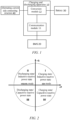
- FIG. 1 is a schematic structural diagram of a charging and discharging apparatus according to an embodiment of the present application.
- a charging and discharging apparatus 10 includes a communication module 11 and a conversion module 12.
- the communication module 11 is communicatively connected to a BMS 20.
- controller area network (CAN) communication may be performed between the communication module 11 and the BMS 20, and a communication manner between the two is not limited.
- the communication module 11 is configured to, under a condition of being in a first energy transmission mode and the BMS 20 not supporting a specific discharging protocol, perform first communication with the BMS 20 based on a universal charging protocol.
- the universal charging protocol may refer to a charging protocol that is commonly used within a specific range and is between an electric vehicle charger and a battery management system.
- it may be a national standard charging protocol, for example, the GB/T 27930-2015 protocol (that is, the communication protocol between the electric vehicle off-board conductive charger and the battery management system, which is carried out on January 1, 2016).
- the universal charging protocol may alternatively be a protocol of another version, which is not limited.
- the universal communication protocol is obtained by extending an existing universal protocol.
- the communication module 11 may notify the BMS 20 of a maximum input capacity of the alternating current side by means of a CML packet (that is, a packet used to notify the BMS 20 of a maximum output capacity of the charger).
- the BMS 20 notifies the communication module 11 of a battery discharging parameter by means of a BCP packet (that is, a packet used to notify the charger of charging parameters of a traction battery).
- the BMS 20 may notify the communication module 11 of a battery discharging demand by means of a BLC packet (that is, a packet used to notify the charger of the battery discharging demand).
- the BMS 20 may further notify the communication module 11 of a total battery charging state by means of a BCS packet (that is, a packet used to notify the charger of the total battery charging state).
- the BMS 20 may further notify the communication module 11 that the BMS 20 suspends discharging by means of a BST packet (that is, a packet used to notify the BMS to suspend charging).
- the communication module 11 may further notify the BMS 20 that the communication module 11 suspends discharging by means of a CST packet (that is, a packet used to notify the charger to suspend charging).
- the specific discharging protocol may refer to a discharging protocol formulated for a discharging process between the charger and the BMS.
- the specific discharging protocol may specify a physical layer, a version of a communication network, a frame format, a protocol data unit format, a network address, and a packet about phases such as a handshake phase and a discharging phase, so as to be applicable to a discharging scenario.
- the communication module 11 may first communicate with the BMS 20 based on a universal charging protocol, and then determine whether the BMS 20 supports a specific discharging protocol in the handshake phase. Specifically, the communication module 11 may determine the protocol version used by the BMS 20 based on the received vehicle handshake message (such as the BHM packet in the GB/T 27930-2015 protocol). Under a condition that the used protocol version does not include the specific discharging protocol, it is determined that the BMS 20 does not support the specific discharging protocol.
- the communication module 11 is further configured to: under a condition of being in the first energy transmission mode and the BMS 20 supporting the specific discharging protocol, perform first communication with the BMS 20 based on the specific discharging protocol.
- the first communication in the present application shall be distinguished from the second communication mentioned in subsequent sections.
- the first communication refers to communication in a battery discharging process
- the second communication refers to communication in a battery charging process.
- the first communication may be communication implemented on the basis of the universal charging protocol communication.
- the first communication may be communication implemented on the basis of the specific discharging protocol communication.
- the communication module 11 is further configured to: under a condition of being in a second energy transmission mode, perform second communication with the BMS based on a universal charging protocol. It should be noted that related description of the second communication may refer to the related description of the previous embodiment, which are not described herein again.
- the communication module 11 is further configured to receive an instruction sent by a user to enter an energy transmission mode.
- the user may select the energy transmission mode and corresponding parameters by means of a mobile phone application or an operation panel of an electronic device, and then generate an instruction based on the selected energy transmission mode and parameters.
- a G2V mode may be selected, and charging parameters may be selected.
- the charging parameters may include charging duration and/or a current charging quantity.
- the current charging quantity may be represented by a battery capacity, or may be represented by a charging interval of a state of charge of the battery.
- a V2G mode or a V2L mode may be selected, and discharging parameters may be selected.
- the discharging parameters may include discharging duration and/or a current discharging quantity.
- the current discharging quantity may be represented by a battery capacity, or may be represented by a discharging interval of a state of charge of the battery.
- the communication module 12 may further calculate a maximum discharging quantity based on battery information sent by the BMS 20, then determine a smaller value between the current discharging quantity sent by the user and the calculated maximum discharging quantity, and update the smaller value to a new current discharging quantity.
- the communication module 11 may further calculate a maximum charging quantity based on battery information sent by the BMS 20, then determine a smaller value between the current charging quantity sent by the user and the calculated maximum charging quantity, and update the smaller value to a new current charging quantity.
- the communication module 11 may calculate the maximum discharging quantity or calculate the maximum charging quantity after the handshake phase and the configuration phase end, that is, after both a positive relay and a negative relay of the electric vehicle are closed.
- one side of the conversion module 12 is connected to the battery 30, and the other side of the conversion module 12 is connected to an alternating current side connecting structure 40.
- the conversion module 12 may implement conversion between direct current and alternating current. Specifically, the conversion module 12 is configured to convert direct current provided by the battery 30 into alternating current and transmit the alternating current to the alternating current side connecting structure 40 in a process of the first communication.
- the conversion module 12 may be implemented as a direct current-alternating current (DCAC) bidirectional conversion module.
- the DCAC bidirectional conversion module can convert direct current input from the direct current side into alternating current and transmit the alternating current to the alternating current side, and can also convert alternating current input from the alternating current side into direct current and transmit the direct current to the direct current side.
- DCAC direct current-alternating current
- an isolated bidirectional full-bridge CLLC resonant circuit may be selected. It should be noted that, for the direct current output by the traction battery of the electric vehicle, its voltage may reach 200 V-500 V, while the alternating current on the alternating current side of the conversion module 12 may usually reach 220 V or 380 V, which implements the galvanic isolation on the battery and the alternating current side connecting structure from each other, and can improve the safety of power consuming devices and the safety of related personnel.
- the conversion module 12 may include a bidirectional full-bridge ACDC circuit part and a CLLLC DC-DC conversion circuit part, where the CLLLC DC-DC conversion circuit part uses an isolation transformer for galvanic isolation, so as to avoid mutual influence between the battery 30 and the alternating current side connecting structure 40.
- the bidirectional full-bridge ACDC circuit part is mainly used for controlling the transmission of bidirectional active power and reactive power on the grid side, and implementing the four-quadrant operation of the alternating current side power.
- the CLLLC DC-DC conversion circuit part is mainly used for adjusting the transmission of active power on the battery side, and controlling the charging and discharging process of the battery.
- active power of the conversion module 12 flows from the alternating current side to the direct current side, and the bidirectional full-bridge ACDC circuit part operates in a rectified state, which shows a step-up characteristic of a boost circuit, controls input current on the alternating current side, and stabilizes voltage on the direct current side; and the CLLLC DC-DC conversion circuit part transmits power from a primary side to a secondary side, charges the battery 30, and stabilizes output voltage or current on the battery side.
- the active power of the conversion module 12 flows reversely from the direct current side to the alternating current side.
- the bidirectional full-bridge ACDC circuit part operates in an inverse state, which shows a step-down characteristic of a buck circuit, and controls output current on the alternating current side.
- the CLLLC DC-DC conversion circuit transmits power from a secondary side to a primary side, discharges the battery, and stabilizes voltage on the direct current side.
- a bridge arm switch unit in the DCAC bidirectional conversion module may be a switch unit made of SiC materials.
- the DCAC bidirectional conversion module may implement a synchronous rectification policy.
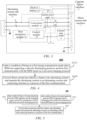
- FIG. 2 is a schematic diagram of a power mode of a conversion module according to the present application.
- the conversion module 12 operates on a P-axis.
- the conversion module 12 may also operate on a Q-axis in a pure reactive power mode.
- the conversion module 12 may simultaneously transmit active and reactive power, perform reactive power compensation and power factor correction when the battery is charging and discharging, and implement four-quadrant operation of the alternating current side in a power circle.
- the conversion module 12 is further configured to convert alternating current provided by the alternating current side power supply into direct current and transmit the direct current to the battery 30 in a process of the second communication.
- a universal charging protocol may be selected to implement communication between the BMS and the charging and discharging apparatus under a condition that the BMS does not support a specific discharging protocol, so that the battery can be discharged under the condition that the BMS does not support the discharging protocol.
- the charging and discharging apparatus 10 may further include a control module 13. The following will describe the control module 13 in detail.
- the control module 13 may control the conversion module 12 based on a control signal after the communication module 11 receives the control signal.
- the control module 13 may control a current conversion direction of the conversion module 12.
- the conversion module 12 may be controlled to convert direct current to alternating current, or alternatively, the conversion module 12 may be controlled to convert alternating current to direct current.
- FIG. 2 is a schematic structural diagram of an exemplary charging and discharging apparatus according to an embodiment of the present application. As shown in FIG. 2 , the charging and discharging apparatus further includes a first switch K1 and a second switch K2, and before the conversion module 12 is controlled to start a conversion operation, the control module 13 may control the first switch K1 and the second switch K2.
- first switch K1 and the second switch K2 may also be controlled to be opened after ending the charging such as ending the G2V mode, or ending the discharging such as ending the V2G mode or the V2L mode. It should be noted that the first switch K1 and the second switch K2 may be relays or semiconductor switches, and specific types of the first switch K1 and the second switch K2 are not limited.
- the control module 13 may obtain discharging parameters by means of the communication module 11. If it is determined that the discharging parameters are reached, the control module 13 controls the conversion module 12 to stop operating. Exemplarily, under a condition that the discharging parameters include discharging duration, the control module 13 controls the conversion module 12 to stop operating after determining that the current discharging process reaches the discharging duration. For another example, if it is determined that a maximum discharging quantity is reached, the conversion module 12 is controlled to stop operating.
- control module 13 may also send a signal of ending the first energy transmission mode to the communication module 11.
- the communication module 11 may notify the BMS 20 to end the discharging based on a universal charging protocol or a specific discharging protocol.
- the communication module 11 also sends a prompt of ending the discharging to a user.
- the control module 13 may obtain charging parameters by means of the communication module 11. If it is determined that the charging parameters are reached, the control module 13 controls the conversion module 12 to stop operating. Exemplarily, under a condition that the charging parameters include charging duration, the control module 13 controls the conversion module 12 to stop operating after determining that the current charging process reaches the charging duration. For another example, if it is determined that a current charging quantity is reached, the conversion module 12 is controlled to stop operating.
- control module 13 may also send a signal of ending the second energy transmission mode to the communication module 11.
- the communication module 11 may notify the BMS 20 to end the charging based on a universal charging protocol.
- the communication module 11 also sends a prompt of ending the charging to a user.
- the control module 13 is further configured to detect whether voltage and/or voltage frequency of the alternating current side power supply is normal at an alternating current interface of the charging and discharging apparatus.
- the conversion module 12 is controlled to start operating.
- the control module 13 can detect whether the voltage and the voltage frequency of the grid are anomalous, and under a condition that the voltage and the voltage frequency of the grid are anomalous, it is forbidden to start energy transmission.
- an anomaly standard of the voltage may be that the voltage is 0, and an anomaly standard of the voltage frequency may be that the voltage frequency is 0.
- control module 13 is further configured to determine a current energy transmission mode, and execute a security policy corresponding to the current energy transmission mode.
- the policy A is to perform insulation detection on the battery 30.
- the policy B is to determine that an alternating current side voltage parameter of the charging and discharging apparatus 10 is within a preset value range.
- the above security policies may be implemented during a handshake phase and during parameter configuration, thereby ensuring safe electrical connection in the charging/discharging process.
- discharging may be performed on the charging and discharging apparatus 10 and the battery, thereby ensuring the contact safety after power cut.
- the charging and discharging apparatus 10 may further include an auxiliary power supply 14.
- auxiliary power supply 14 The following will describe the auxiliary power supply 14 in detail.
- FIG. 3 is a schematic structural diagram of an exemplary charging and discharging apparatus according to an embodiment of the present application.
- the charging and discharging apparatus may be connected to a first connection line and a second connection line.
- the first connection line is a line between a conversion module 12 and an alternating current side connecting structure 40.
- the second connection line is a line between the conversion module 12 and a battery 30. Therefore, the function of obtaining power from the alternating current side connecting structure 40 or the battery 30 may be implemented.
- the auxiliary power supply 14 may also be connected to a low-voltage power consuming device such as a control module 12 for supplying power to the low-voltage power consuming device.
- the auxiliary power supply 14 uses alternating current provided by the alternating current side power supply to supply power to the charging and discharging apparatus 10.
- the auxiliary power supply 14 may also supply power to a low-voltage power consuming device of an electric vehicle.
- A+ and A- interfaces in a direct current side interface 17 in FIG. 3 are used to supply power to the low-voltage power consuming device of the electric vehicle.
- the auxiliary power supply uses direct current provided by a low-voltage power supply to supply power to the charging and discharging apparatus 10 before being connected to the battery 30, and uses the direct current provided by the battery 30 to supply power to the charging and discharging apparatus 10 after being connected to the battery 30.
- the low-voltage power supply includes a built-in battery 15 and/or a vehicle-mounted cigarette lighter.
- the auxiliary power supply 14 may be connected to the vehicle-mounted cigarette lighter by means of a cigarette lighter interface 19.
- the cigarette lighter interface 19 may be implemented as a standard-compliant cigarette lighter connector.
- the built-in battery 15 may be of a low voltage, such as 12 V.
- the auxiliary power supply 14 its priorities of obtaining power may be as follows in descending order: the alternating current side power supply, the battery 30, and the low-voltage power supply.
- the priority of the built-in battery 15 may be higher than that of the vehicle-mounted cigarette lighter.
- power is obtained from the vehicle-mounted cigarette lighter. Whether the battery capacity of the built-in battery is too low may be determined by a battery capacity indicator light of the built-in battery 15.
- the charging and discharging apparatus 10 under a condition that the charging and discharging apparatus 10 is in a dormant state, it may be woken up by the built-in battery 15 or the vehicle-mounted cigarette lighter supplying power to it.
- the charging and discharging apparatus 10 further includes a heat dissipation module 16.
- the heat dissipation module 16 is configured to dissipate heat for each functional module or physical structure of the charging and discharging apparatus 10, so as to ensure that heat-dissipated components operate in a suitable temperature range.
- the heat dissipation module 16 may be implemented as a heat dissipation structure such as a fan or a water cooling module, and a specific structure and type thereof are not limited.
- the heat dissipation module 16 is connected to the control module 13.
- the control module 13 collects a temperature of the charging and discharging apparatus 10, and if it is determined that the temperature of the charging and discharging apparatus 10 is higher than a preset temperature threshold, controls the heat dissipation module 16 to start a heat dissipation operation.
- an ambient temperature of the charging and discharging apparatus 10 or temperatures of easily-heated components of the charging and discharging apparatus 10 may be collected as the temperature of the charging and discharging apparatus 10.
- the easily-heated components may be a switch unit of the conversion module 12, or may be a transformer.
- control module 13 further controls the heat dissipation module 16 to stop the heat dissipation operation.
- the charging and discharging apparatus 10 further includes a direct current side interface 17.
- the direct current side interface may be implemented as a direct current charging gun.
- the direct current charging gun may be a direct current charging gun that conforms to the GB/T 18487 standard.
- the direct current side interface 17 may include the following interfaces:
- the charging and discharging apparatus 10 further includes an alternating current side interface 18.
- the alternating current side interface is a standard alternating current pin plug (referred to as a male connector for short) and a standard alternating current hole plug (referred to as a female connector for short).
- the alternating current side interface 18 may include the following interfaces:
- the charging and discharging apparatus 10 may further include: a third switch QF. Still referring to FIG. 3 , the third switch QF may be provided on a connection line between the conversion module 12 and the alternating current side connecting structure 40. The third switch QF may control the connection or disconnection between the charging and discharging apparatus 10 and the alternating current side connecting structure 40.
- the embodiments of the present application will describe a power transmission method of the charging and discharging apparatus provided in the embodiments of the present application in detail with reference to FIG. 4 .
- FIG. 4 is a schematic flowchart of an embodiment of a power transmission method of a charging and discharging apparatus according to the present application. Each step in FIG. 4 may be performed by the charging and discharging apparatus 10. As shown in FIG. 4 , the power transmission method 400 of the charging and discharging apparatus may specifically include S410 to S420.
- Direct current provided by a battery is converted into alternating current and the alternating current is transmitted to an alternating current side connecting structure in a process of the first communication.
- the first energy transmission mode is a mode in which the battery transmits power to the alternating current side connecting structure of the apparatus.
- FIG. 5 is a schematic flowchart of another embodiment of a power transmission method of a charging and discharging apparatus according to the present application. As shown in FIG. 5 , the power transmission method 400 of the charging and discharging apparatus further includes S430.
- the alternating current side connecting structure is an alternating current power supply
- the power transmission method 400 of the charging and discharging apparatus further includes: under a condition of being in a second energy transmission mode, performing second communication with the BMS based on a universal charging protocol; and converting alternating current provided by the alternating current power supply into direct current in a process of the second communication.
- the second energy transmission mode is a mode in which the alternating current power supply transmits power to the battery.
- the universal charging protocol is obtained by extending an existing universal charging protocol.
- the power transmission method 400 of the charging and discharging apparatus further includes:
- the security policy corresponding to the first sub-mode includes: performing insulation detection on the battery, and determining that an alternating current side voltage parameter of the apparatus is within a preset value range;
- the first sub-mode is a mode in which the battery transmits power to the alternating current side power supply of the apparatus.
- the second sub-mode is a mode in which the battery transmits power to the alternating current side load of the apparatus.
- the second energy transmission mode is a mode in which the alternating current side power supply of the apparatus transmits power to the battery.
- the power transmission method 400 of the charging and discharging apparatus further includes:
- the auxiliary direct current power supply includes a power supply battery of the apparatus and/or a vehicle-mounted cigarette lighter.
- a universal charging protocol may be selected to implement communication between the BMS and the charging and discharging apparatus under a condition that the BMS does not support a specific discharging protocol, so that the battery can be discharged under the condition that the BMS does not support the discharging protocol.
- the functional modules shown in the above embodiments may be implemented as hardware, software, firmware, or a combination thereof.
- the functional modules may be, for example, an electronic circuit, an application-specific integrated circuit (ASIC), appropriate firmware, a plug-in, or a function card.
- ASIC application-specific integrated circuit
- the elements of the present application are programs or code segments used to perform required tasks.
- the program or code segment may be stored in a machine-readable medium, or transmitted on a transmission medium or a communication link by means of a data signal carried in a carrier wave.
- "Machine-readable medium" may include any medium that can store or transmit information. Examples of the machine-readable storage medium may include a non-transitory computer-readable storage medium, for example, a read-only memory (ROM), a random access memory (RAM), a magnetic disk, an optical disc, or the like.
Landscapes
- Engineering & Computer Science (AREA)
- Power Engineering (AREA)
- Transportation (AREA)
- Mechanical Engineering (AREA)
- Manufacturing & Machinery (AREA)
- Chemical & Material Sciences (AREA)
- Chemical Kinetics & Catalysis (AREA)
- Electrochemistry (AREA)
- General Chemical & Material Sciences (AREA)
- Microelectronics & Electronic Packaging (AREA)
- Life Sciences & Earth Sciences (AREA)
- Sustainable Development (AREA)
- Sustainable Energy (AREA)
- Thermal Sciences (AREA)
- Physics & Mathematics (AREA)
- Charge And Discharge Circuits For Batteries Or The Like (AREA)
Applications Claiming Priority (2)
| Application Number | Priority Date | Filing Date | Title |
|---|---|---|---|
| CN202011425796.7A CN114614515A (zh) | 2020-12-08 | 2020-12-08 | 充放电装置及其输电方法 |
| PCT/CN2021/129136 WO2022121588A1 (fr) | 2020-12-08 | 2021-11-05 | Appareil de charge et de décharge et son procédé de transmission de puissance |
Publications (3)
| Publication Number | Publication Date |
|---|---|
| EP4199298A1 true EP4199298A1 (fr) | 2023-06-21 |
| EP4199298A4 EP4199298A4 (fr) | 2024-04-10 |
| EP4199298B1 EP4199298B1 (fr) | 2026-03-25 |
Family
ID=81855685
Family Applications (1)
| Application Number | Title | Priority Date | Filing Date |
|---|---|---|---|
| EP21902295.1A Active EP4199298B1 (fr) | 2020-12-08 | 2021-11-05 | Appareil de charge et de décharge et son procédé de transmission de puissance |
Country Status (4)
| Country | Link |
|---|---|
| US (1) | US20230219457A1 (fr) |
| EP (1) | EP4199298B1 (fr) |
| CN (2) | CN120127802A (fr) |
| WO (1) | WO2022121588A1 (fr) |
Families Citing this family (4)
| Publication number | Priority date | Publication date | Assignee | Title |
|---|---|---|---|---|
| CN115313455A (zh) * | 2022-08-10 | 2022-11-08 | 安徽卓越电气有限公司 | 一种储能式多模移动充电控制电路及其控制方法 |
| DE102022133573A1 (de) * | 2022-12-16 | 2024-06-27 | Bayerische Motoren Werke Aktiengesellschaft | Bidirektionales Laden eines Elektrofahrzeugs an einem Lokalnetz |
| CN116505603A (zh) * | 2023-03-02 | 2023-07-28 | 广州纽威光电科技有限公司 | 基于电动汽车充电协议对的dc-ac变换装置 |
| CN117901692A (zh) * | 2023-11-23 | 2024-04-19 | 安徽维德电源有限公司 | 一种大功率电动车辆充电系统 |
Family Cites Families (11)
| Publication number | Priority date | Publication date | Assignee | Title |
|---|---|---|---|---|
| EP3118962A4 (fr) * | 2014-03-12 | 2017-11-01 | Nec Corporation | Système de partage de batterie d'accumulateurs, dispositif de traitement d'informations, procédé de partage de batterie d'accumulateurs, et programme de partage de batterie d'accumulateurs d'enregistrement de support d'enregistrement |
| CN106740168A (zh) * | 2016-11-18 | 2017-05-31 | 许继电源有限公司 | 一种电动汽车bms通信协议版本识别方法及装置 |
| CN108173323A (zh) * | 2016-12-05 | 2018-06-15 | 飞宏科技股份有限公司 | 一种双向车载充放电系统及其方法 |
| CN108407625B (zh) * | 2017-02-10 | 2024-01-26 | 石家庄汉卓能源科技有限公司 | 一种用于新能源汽车双向充放电系统 |
| CN106926739A (zh) * | 2017-04-24 | 2017-07-07 | 英特瓦特(深圳)科技有限公司 | 一种从电动车到电动车的可移动的充放电系统 |
| KR20180121105A (ko) * | 2017-04-28 | 2018-11-07 | 현대자동차주식회사 | 스마트그리드용 전기자동차의 양방향 충방전 방법 및 장치 |
| CN107069887B (zh) * | 2017-05-18 | 2023-08-29 | 云杉智慧新能源技术有限公司 | 一种电动车充放电系统 |
| CN107834658B (zh) * | 2017-12-01 | 2023-09-26 | 河北地标电力科技有限公司 | 新能源汽车v2v应急充电装置及其充电控制方法 |
| CN207719855U (zh) * | 2018-01-09 | 2018-08-10 | 深圳市普兰德储能技术有限公司 | 一种充储一体化移动补电车系统 |
| CN108206570B (zh) * | 2018-02-01 | 2024-02-27 | 中国第一汽车股份有限公司 | 电动汽车车辆间直流电力传输系统及控制方法 |
| CN110154825A (zh) * | 2019-05-30 | 2019-08-23 | 奇瑞新能源汽车技术有限公司 | 电动汽车动力电池对车外负载放电的控制方法 |
-
2020
- 2020-12-08 CN CN202510404045.3A patent/CN120127802A/zh active Pending
- 2020-12-08 CN CN202011425796.7A patent/CN114614515A/zh active Pending
-
2021
- 2021-11-05 WO PCT/CN2021/129136 patent/WO2022121588A1/fr not_active Ceased
- 2021-11-05 EP EP21902295.1A patent/EP4199298B1/fr active Active
-
2023
- 2023-03-21 US US18/187,158 patent/US20230219457A1/en active Pending
Also Published As
| Publication number | Publication date |
|---|---|
| CN120127802A (zh) | 2025-06-10 |
| US20230219457A1 (en) | 2023-07-13 |
| EP4199298A4 (fr) | 2024-04-10 |
| CN114614515A (zh) | 2022-06-10 |
| EP4199298B1 (fr) | 2026-03-25 |
| WO2022121588A1 (fr) | 2022-06-16 |
Similar Documents
| Publication | Publication Date | Title |
|---|---|---|
| EP4199298B1 (fr) | Appareil de charge et de décharge et son procédé de transmission de puissance | |
| CN116325420B (zh) | 电池充电的方法和充放电装置 | |
| EP4220885B1 (fr) | Appareil de charge/décharge, procédé de charge et de décharge de batterie, et système de charge/décharge | |
| KR102893181B1 (ko) | 배터리 충전 방법, 배터리 관리 시스템 및 충방전 장치 | |
| EP4068561B1 (fr) | Procédé de charge et dispositif de conversion de puissance | |
| CN102638085A (zh) | 电动汽车蓄电池智能充电及电池管理装置 | |
| CN116325286B (zh) | 充放电装置、电池充电的方法和充放电系统 | |
| JP2024546958A (ja) | 充電デバイス | |
| KR20230019380A (ko) | 충방전 장치 및 배터리 충전 방법 | |
| EP4059762A1 (fr) | Véhicule électrique et procédé de commande de charge d'un véhicule électrique | |
| CN115885407B (zh) | 充放电装置、电池充电的方法和充放电系统 | |
| US20190001834A1 (en) | Charge/discharge apparatus | |
| JP2020018120A (ja) | 充放電装置および充放電システム | |
| CN212500004U (zh) | 电池充电与加热系统 | |
| CN110266030B (zh) | 一种控制装置及控制方法 | |
| CN120454261A (zh) | 一种用于房车的智能储能系统 | |
| CN120481722A (zh) | 一种动力电池充电方法及系统 | |
| JP6009991B2 (ja) | 車両および電力システム |
Legal Events
| Date | Code | Title | Description |
|---|---|---|---|
| STAA | Information on the status of an ep patent application or granted ep patent |
Free format text: STATUS: THE INTERNATIONAL PUBLICATION HAS BEEN MADE |
|
| PUAI | Public reference made under article 153(3) epc to a published international application that has entered the european phase |
Free format text: ORIGINAL CODE: 0009012 |
|
| STAA | Information on the status of an ep patent application or granted ep patent |
Free format text: STATUS: REQUEST FOR EXAMINATION WAS MADE |
|
| 17P | Request for examination filed |
Effective date: 20230316 |
|
| AK | Designated contracting states |
Kind code of ref document: A1 Designated state(s): AL AT BE BG CH CY CZ DE DK EE ES FI FR GB GR HR HU IE IS IT LI LT LU LV MC MK MT NL NO PL PT RO RS SE SI SK SM TR |
|
| REG | Reference to a national code |
Ref country code: DE Ref legal event code: R079 Free format text: PREVIOUS MAIN CLASS: H02J0007000000 Ipc: H02J0003320000 Ref country code: DE Ref legal event code: R079 Ref document number: 602021050856 Country of ref document: DE Free format text: PREVIOUS MAIN CLASS: H02J0007000000 Ipc: H02J0003320000 |
|
| DAV | Request for validation of the european patent (deleted) | ||
| DAX | Request for extension of the european patent (deleted) | ||
| A4 | Supplementary search report drawn up and despatched |
Effective date: 20240311 |
|
| RIC1 | Information provided on ipc code assigned before grant |
Ipc: H01M 10/42 20060101ALN20240304BHEP Ipc: H01M 10/44 20060101ALI20240304BHEP Ipc: B60L 55/00 20190101ALI20240304BHEP Ipc: B60L 53/20 20190101ALI20240304BHEP Ipc: B60L 1/00 20060101ALI20240304BHEP Ipc: H02J 7/00 20060101ALI20240304BHEP Ipc: H02J 3/32 20060101AFI20240304BHEP |
|
| RAP1 | Party data changed (applicant data changed or rights of an application transferred) |
Owner name: CONTEMPORARY AMPEREX TECHNOLOGY(HONG KONG) LIMITED |
|
| GRAP | Despatch of communication of intention to grant a patent |
Free format text: ORIGINAL CODE: EPIDOSNIGR1 |
|
| STAA | Information on the status of an ep patent application or granted ep patent |
Free format text: STATUS: GRANT OF PATENT IS INTENDED |
|
| RIC1 | Information provided on ipc code assigned before grant |
Ipc: H02J 3/32 20060101AFI20251106BHEP Ipc: H02J 7/00 20060101ALI20251106BHEP Ipc: B60L 1/00 20060101ALI20251106BHEP Ipc: B60L 53/20 20190101ALI20251106BHEP Ipc: B60L 55/00 20190101ALI20251106BHEP Ipc: H01M 10/44 20060101ALI20251106BHEP Ipc: H01M 10/42 20060101ALN20251106BHEP |
|
| INTG | Intention to grant announced |
Effective date: 20251125 |
|
| GRAS | Grant fee paid |
Free format text: ORIGINAL CODE: EPIDOSNIGR3 |
|
| GRAA | (expected) grant |
Free format text: ORIGINAL CODE: 0009210 |
|
| STAA | Information on the status of an ep patent application or granted ep patent |
Free format text: STATUS: THE PATENT HAS BEEN GRANTED |
|
| AK | Designated contracting states |
Kind code of ref document: B1 Designated state(s): AL AT BE BG CH CY CZ DE DK EE ES FI FR GB GR HR HU IE IS IT LI LT LU LV MC MK MT NL NO PL PT RO RS SE SI SK SM TR |
|
| REG | Reference to a national code |
Ref country code: CH Ref legal event code: F10 Free format text: ST27 STATUS EVENT CODE: U-0-0-F10-F00 (AS PROVIDED BY THE NATIONAL OFFICE) Effective date: 20260325 Ref country code: GB Ref legal event code: FG4D |
|
| REG | Reference to a national code |
Ref country code: DE Ref legal event code: R096 Ref document number: 602021050856 Country of ref document: DE |
|
| REG | Reference to a national code |
Ref country code: IE Ref legal event code: FG4D |